EP2569043B1 - Stentless support structure - Google Patents
Stentless support structure Download PDFInfo
- Publication number
- EP2569043B1 EP2569043B1 EP11781175.2A EP11781175A EP2569043B1 EP 2569043 B1 EP2569043 B1 EP 2569043B1 EP 11781175 A EP11781175 A EP 11781175A EP 2569043 B1 EP2569043 B1 EP 2569043B1
- Authority
- EP
- European Patent Office
- Prior art keywords
- support structure
- valve
- invertible
- distal end
- catheter
- Prior art date
- Legal status (The legal status is an assumption and is not a legal conclusion. Google has not performed a legal analysis and makes no representation as to the accuracy of the status listed.)
- Active
Links
- 230000007246 mechanism Effects 0.000 claims description 9
- 210000003709 heart valve Anatomy 0.000 claims description 3
- 230000004323 axial length Effects 0.000 claims 1
- 238000000034 method Methods 0.000 description 19
- 210000002216 heart Anatomy 0.000 description 15
- 239000000463 material Substances 0.000 description 9
- 238000013459 approach Methods 0.000 description 8
- 229910001000 nickel titanium Inorganic materials 0.000 description 6
- HLXZNVUGXRDIFK-UHFFFAOYSA-N nickel titanium Chemical compound [Ti].[Ti].[Ti].[Ti].[Ti].[Ti].[Ti].[Ti].[Ti].[Ti].[Ti].[Ni].[Ni].[Ni].[Ni].[Ni].[Ni].[Ni].[Ni].[Ni].[Ni].[Ni].[Ni].[Ni].[Ni] HLXZNVUGXRDIFK-UHFFFAOYSA-N 0.000 description 6
- 210000005166 vasculature Anatomy 0.000 description 6
- 210000001765 aortic valve Anatomy 0.000 description 5
- 210000001519 tissue Anatomy 0.000 description 5
- 230000017531 blood circulation Effects 0.000 description 4
- 210000005240 left ventricle Anatomy 0.000 description 4
- 238000001356 surgical procedure Methods 0.000 description 4
- 210000000709 aorta Anatomy 0.000 description 3
- 208000014674 injury Diseases 0.000 description 3
- 229910001285 shape-memory alloy Inorganic materials 0.000 description 3
- 230000008733 trauma Effects 0.000 description 3
- 208000031481 Pathologic Constriction Diseases 0.000 description 2
- 239000008280 blood Substances 0.000 description 2
- 210000004369 blood Anatomy 0.000 description 2
- 210000001105 femoral artery Anatomy 0.000 description 2
- 230000006870 function Effects 0.000 description 2
- 238000002513 implantation Methods 0.000 description 2
- 238000011065 in-situ storage Methods 0.000 description 2
- 230000008569 process Effects 0.000 description 2
- 238000011084 recovery Methods 0.000 description 2
- 239000010935 stainless steel Substances 0.000 description 2
- 229910001220 stainless steel Inorganic materials 0.000 description 2
- 230000036262 stenosis Effects 0.000 description 2
- 208000037804 stenosis Diseases 0.000 description 2
- 208000037260 Atherosclerotic Plaque Diseases 0.000 description 1
- 208000032750 Device leakage Diseases 0.000 description 1
- 206010019280 Heart failures Diseases 0.000 description 1
- 206010067171 Regurgitation Diseases 0.000 description 1
- 208000007536 Thrombosis Diseases 0.000 description 1
- 239000000853 adhesive Substances 0.000 description 1
- 230000001070 adhesive effect Effects 0.000 description 1
- 229910045601 alloy Inorganic materials 0.000 description 1
- 239000000956 alloy Substances 0.000 description 1
- 210000001367 artery Anatomy 0.000 description 1
- 238000010009 beating Methods 0.000 description 1
- 238000009954 braiding Methods 0.000 description 1
- 230000002612 cardiopulmonary effect Effects 0.000 description 1
- 238000013130 cardiovascular surgery Methods 0.000 description 1
- 210000000748 cardiovascular system Anatomy 0.000 description 1
- 238000010276 construction Methods 0.000 description 1
- 201000010099 disease Diseases 0.000 description 1
- 208000037265 diseases, disorders, signs and symptoms Diseases 0.000 description 1
- 230000005489 elastic deformation Effects 0.000 description 1
- 239000013013 elastic material Substances 0.000 description 1
- 230000003073 embolic effect Effects 0.000 description 1
- 239000004744 fabric Substances 0.000 description 1
- 239000000835 fiber Substances 0.000 description 1
- 230000004927 fusion Effects 0.000 description 1
- 210000001308 heart ventricle Anatomy 0.000 description 1
- 238000009998 heat setting Methods 0.000 description 1
- 238000010438 heat treatment Methods 0.000 description 1
- 238000012977 invasive surgical procedure Methods 0.000 description 1
- 230000002262 irrigation Effects 0.000 description 1
- 238000003973 irrigation Methods 0.000 description 1
- 238000004519 manufacturing process Methods 0.000 description 1
- 229910052751 metal Inorganic materials 0.000 description 1
- 239000002184 metal Substances 0.000 description 1
- 150000002739 metals Chemical class 0.000 description 1
- 238000012986 modification Methods 0.000 description 1
- 230000004048 modification Effects 0.000 description 1
- 210000004165 myocardium Anatomy 0.000 description 1
- RVTZCBVAJQQJTK-UHFFFAOYSA-N oxygen(2-);zirconium(4+) Chemical compound [O-2].[O-2].[Zr+4] RVTZCBVAJQQJTK-UHFFFAOYSA-N 0.000 description 1
- 229920000642 polymer Polymers 0.000 description 1
- 230000002265 prevention Effects 0.000 description 1
- 230000002787 reinforcement Effects 0.000 description 1
- 238000007789 sealing Methods 0.000 description 1
- 239000012781 shape memory material Substances 0.000 description 1
- 238000002560 therapeutic procedure Methods 0.000 description 1
- 230000008719 thickening Effects 0.000 description 1
- 238000011144 upstream manufacturing Methods 0.000 description 1
- 230000002792 vascular Effects 0.000 description 1
- 208000019553 vascular disease Diseases 0.000 description 1
- 210000003462 vein Anatomy 0.000 description 1
Images


Classifications
-
- A—HUMAN NECESSITIES
- A61—MEDICAL OR VETERINARY SCIENCE; HYGIENE
- A61F—FILTERS IMPLANTABLE INTO BLOOD VESSELS; PROSTHESES; DEVICES PROVIDING PATENCY TO, OR PREVENTING COLLAPSING OF, TUBULAR STRUCTURES OF THE BODY, e.g. STENTS; ORTHOPAEDIC, NURSING OR CONTRACEPTIVE DEVICES; FOMENTATION; TREATMENT OR PROTECTION OF EYES OR EARS; BANDAGES, DRESSINGS OR ABSORBENT PADS; FIRST-AID KITS
- A61F2/00—Filters implantable into blood vessels; Prostheses, i.e. artificial substitutes or replacements for parts of the body; Appliances for connecting them with the body; Devices providing patency to, or preventing collapsing of, tubular structures of the body, e.g. stents
- A61F2/02—Prostheses implantable into the body
- A61F2/24—Heart valves ; Vascular valves, e.g. venous valves; Heart implants, e.g. passive devices for improving the function of the native valve or the heart muscle; Transmyocardial revascularisation [TMR] devices; Valves implantable in the body
- A61F2/2427—Devices for manipulating or deploying heart valves during implantation
- A61F2/2436—Deployment by retracting a sheath
-
- A—HUMAN NECESSITIES
- A61—MEDICAL OR VETERINARY SCIENCE; HYGIENE
- A61F—FILTERS IMPLANTABLE INTO BLOOD VESSELS; PROSTHESES; DEVICES PROVIDING PATENCY TO, OR PREVENTING COLLAPSING OF, TUBULAR STRUCTURES OF THE BODY, e.g. STENTS; ORTHOPAEDIC, NURSING OR CONTRACEPTIVE DEVICES; FOMENTATION; TREATMENT OR PROTECTION OF EYES OR EARS; BANDAGES, DRESSINGS OR ABSORBENT PADS; FIRST-AID KITS
- A61F2/00—Filters implantable into blood vessels; Prostheses, i.e. artificial substitutes or replacements for parts of the body; Appliances for connecting them with the body; Devices providing patency to, or preventing collapsing of, tubular structures of the body, e.g. stents
- A61F2/02—Prostheses implantable into the body
- A61F2/24—Heart valves ; Vascular valves, e.g. venous valves; Heart implants, e.g. passive devices for improving the function of the native valve or the heart muscle; Transmyocardial revascularisation [TMR] devices; Valves implantable in the body
- A61F2/2412—Heart valves ; Vascular valves, e.g. venous valves; Heart implants, e.g. passive devices for improving the function of the native valve or the heart muscle; Transmyocardial revascularisation [TMR] devices; Valves implantable in the body with soft flexible valve members, e.g. tissue valves shaped like natural valves
- A61F2/2418—Scaffolds therefor, e.g. support stents
-
- A—HUMAN NECESSITIES
- A61—MEDICAL OR VETERINARY SCIENCE; HYGIENE
- A61F—FILTERS IMPLANTABLE INTO BLOOD VESSELS; PROSTHESES; DEVICES PROVIDING PATENCY TO, OR PREVENTING COLLAPSING OF, TUBULAR STRUCTURES OF THE BODY, e.g. STENTS; ORTHOPAEDIC, NURSING OR CONTRACEPTIVE DEVICES; FOMENTATION; TREATMENT OR PROTECTION OF EYES OR EARS; BANDAGES, DRESSINGS OR ABSORBENT PADS; FIRST-AID KITS
- A61F2/00—Filters implantable into blood vessels; Prostheses, i.e. artificial substitutes or replacements for parts of the body; Appliances for connecting them with the body; Devices providing patency to, or preventing collapsing of, tubular structures of the body, e.g. stents
- A61F2/02—Prostheses implantable into the body
- A61F2/24—Heart valves ; Vascular valves, e.g. venous valves; Heart implants, e.g. passive devices for improving the function of the native valve or the heart muscle; Transmyocardial revascularisation [TMR] devices; Valves implantable in the body
- A61F2/2442—Annuloplasty rings or inserts for correcting the valve shape; Implants for improving the function of a native heart valve
- A61F2/2445—Annuloplasty rings in direct contact with the valve annulus
-
- A—HUMAN NECESSITIES
- A61—MEDICAL OR VETERINARY SCIENCE; HYGIENE
- A61F—FILTERS IMPLANTABLE INTO BLOOD VESSELS; PROSTHESES; DEVICES PROVIDING PATENCY TO, OR PREVENTING COLLAPSING OF, TUBULAR STRUCTURES OF THE BODY, e.g. STENTS; ORTHOPAEDIC, NURSING OR CONTRACEPTIVE DEVICES; FOMENTATION; TREATMENT OR PROTECTION OF EYES OR EARS; BANDAGES, DRESSINGS OR ABSORBENT PADS; FIRST-AID KITS
- A61F2/00—Filters implantable into blood vessels; Prostheses, i.e. artificial substitutes or replacements for parts of the body; Appliances for connecting them with the body; Devices providing patency to, or preventing collapsing of, tubular structures of the body, e.g. stents
- A61F2/02—Prostheses implantable into the body
- A61F2/24—Heart valves ; Vascular valves, e.g. venous valves; Heart implants, e.g. passive devices for improving the function of the native valve or the heart muscle; Transmyocardial revascularisation [TMR] devices; Valves implantable in the body
- A61F2/2442—Annuloplasty rings or inserts for correcting the valve shape; Implants for improving the function of a native heart valve
- A61F2/2466—Delivery devices therefor
-
- A—HUMAN NECESSITIES
- A61—MEDICAL OR VETERINARY SCIENCE; HYGIENE
- A61F—FILTERS IMPLANTABLE INTO BLOOD VESSELS; PROSTHESES; DEVICES PROVIDING PATENCY TO, OR PREVENTING COLLAPSING OF, TUBULAR STRUCTURES OF THE BODY, e.g. STENTS; ORTHOPAEDIC, NURSING OR CONTRACEPTIVE DEVICES; FOMENTATION; TREATMENT OR PROTECTION OF EYES OR EARS; BANDAGES, DRESSINGS OR ABSORBENT PADS; FIRST-AID KITS
- A61F2/00—Filters implantable into blood vessels; Prostheses, i.e. artificial substitutes or replacements for parts of the body; Appliances for connecting them with the body; Devices providing patency to, or preventing collapsing of, tubular structures of the body, e.g. stents
- A61F2/82—Devices providing patency to, or preventing collapsing of, tubular structures of the body, e.g. stents
- A61F2/86—Stents in a form characterised by the wire-like elements; Stents in the form characterised by a net-like or mesh-like structure
- A61F2/90—Stents in a form characterised by the wire-like elements; Stents in the form characterised by a net-like or mesh-like structure characterised by a net-like or mesh-like structure
-
- A—HUMAN NECESSITIES
- A61—MEDICAL OR VETERINARY SCIENCE; HYGIENE
- A61F—FILTERS IMPLANTABLE INTO BLOOD VESSELS; PROSTHESES; DEVICES PROVIDING PATENCY TO, OR PREVENTING COLLAPSING OF, TUBULAR STRUCTURES OF THE BODY, e.g. STENTS; ORTHOPAEDIC, NURSING OR CONTRACEPTIVE DEVICES; FOMENTATION; TREATMENT OR PROTECTION OF EYES OR EARS; BANDAGES, DRESSINGS OR ABSORBENT PADS; FIRST-AID KITS
- A61F2/00—Filters implantable into blood vessels; Prostheses, i.e. artificial substitutes or replacements for parts of the body; Appliances for connecting them with the body; Devices providing patency to, or preventing collapsing of, tubular structures of the body, e.g. stents
- A61F2/95—Instruments specially adapted for placement or removal of stents or stent-grafts
-
- A—HUMAN NECESSITIES
- A61—MEDICAL OR VETERINARY SCIENCE; HYGIENE
- A61F—FILTERS IMPLANTABLE INTO BLOOD VESSELS; PROSTHESES; DEVICES PROVIDING PATENCY TO, OR PREVENTING COLLAPSING OF, TUBULAR STRUCTURES OF THE BODY, e.g. STENTS; ORTHOPAEDIC, NURSING OR CONTRACEPTIVE DEVICES; FOMENTATION; TREATMENT OR PROTECTION OF EYES OR EARS; BANDAGES, DRESSINGS OR ABSORBENT PADS; FIRST-AID KITS
- A61F2210/00—Particular material properties of prostheses classified in groups A61F2/00 - A61F2/26 or A61F2/82 or A61F9/00 or A61F11/00 or subgroups thereof
- A61F2210/0076—Particular material properties of prostheses classified in groups A61F2/00 - A61F2/26 or A61F2/82 or A61F9/00 or A61F11/00 or subgroups thereof multilayered, e.g. laminated structures
-
- A—HUMAN NECESSITIES
- A61—MEDICAL OR VETERINARY SCIENCE; HYGIENE
- A61F—FILTERS IMPLANTABLE INTO BLOOD VESSELS; PROSTHESES; DEVICES PROVIDING PATENCY TO, OR PREVENTING COLLAPSING OF, TUBULAR STRUCTURES OF THE BODY, e.g. STENTS; ORTHOPAEDIC, NURSING OR CONTRACEPTIVE DEVICES; FOMENTATION; TREATMENT OR PROTECTION OF EYES OR EARS; BANDAGES, DRESSINGS OR ABSORBENT PADS; FIRST-AID KITS
- A61F2230/00—Geometry of prostheses classified in groups A61F2/00 - A61F2/26 or A61F2/82 or A61F9/00 or A61F11/00 or subgroups thereof
- A61F2230/0063—Three-dimensional shapes
- A61F2230/0067—Three-dimensional shapes conical
Definitions
- stents usually fall into one of two categories: self-expanding stents and expandable stents.
- Self-expanding stents are compressed when loaded into a catheter and expand to their original, non-compressed size when released from the catheter. These are typically made of Nitinol.
- Balloon expandable stents are loaded into a catheter in a compressed but relaxed state. These are typically made from stainless steel or other malleable metals. A balloon is placed within the stent. Upon deployment, the catheter is retracted and the balloon inflated, thereby expanding the stent to a desired size. Both of these stent types exhibit significant force upon expansion.
- the force is usually strong enough to crack or pop thrombosis, thereby causing pieces of atherosclerotic plaque to dislodge and become emboli. If the stent is being implanted to treat a stenosed vessel, a certain degree of such expansion is desirable. However, if the stent is merely being implanted to displace native valves, less force may be desirable to reduce the chance of creating emboli.
- expanded stents usually have members that are too spaced apart to be effective to trap any dislodged material. Often, secondary precautions must be taken including the use of nets and irrigation ports.
- the third drawback is due to the relative inflexibility of stents.
- Stents typically rely on the elastic nature of the native vessel to conform around the stent. Stents used to open a restricted vessel do not require a seal between the vessel and the stent.
- a seal between the stent and the vessel is necessary to prevent paravalvular leakage. Due to the non-conforming nature of stents, this seal is hard to achieve, especially when displacing stenosed valve leaflets.
- stents are not easily retrievable. Once deployed, a stent may not be recompressed and drawn back into the catheter for repositioning due to the non-elastic deformation (stainless steel) or the radial force required to maintain the stent in place (Nitinol). Thus, if a physician is unsatisfied with the deployed location or orientation of a stent, there is little he or she can do to correct the problem.
- the sixth drawback listed above is that the combination of the valve within the stent greatly increases the size of the system required to deliver the prosthetic device. As a result, the size of the entry hole into the vasculature is large and often precludes therapy, particularly in children, smaller adults or patients with pre-existing vascular disease.
- Embodiments provide a tubular mesh support structure for a native lumen that is capable of being delivered via a very small diameter delivery catheter.
- the tubular mesh is formed one or more fine strands braided together into an elongate tube.
- the strands may be fibrous, non-fibrous, multifilament, or monofilament.
- the strands exhibit shape memory such that the elongate tube may be formed into a desired folded shape, then stretched out into a very small diameter, elongated configuration. The small diameter, elongated configuration makes a very small diameter delivery catheter possible.
- the elongated tube Upon deployment, the elongated tube is slowly pushed out of the delivery catheter, where it gradually regains its folded, constructed configuration.
- the tube conforms to the internal geometries of the target vessel.
- the braid effectively traps all emboli that may be released from the vessel walls.
- the tube continues to be pushed from the delivery catheter, it begins to fold in upon itself as it regains its constructed configuration. As it folds in upon itself, the forces exerted by each layer add together, making the structure incrementally stronger. Thus, varying levels of strength may be achieved without changing the elongated diameter of the device.
- the valve can be attached such that the valve or other structure (such as a filter) in its elongated configuration within the delivery catheter does not reside within the elongated tube, but on deployment can be positioned in, above or below the tube.
- the valve or other structure such as a filter
- the valve support 10 includes a first end 12, a second end 14 and an elongate tubular body 16 extending between the first end 12 and the second end 14.
- the elongate tubular body 16 is preferably formed from one or a plurality of braided strands 18.
- the braided strands 18 are strands of a super-elastic or shape memory material such as Nitinol.
- the strands are braided to form a tube having a central lumen 20 passing therethrough.
- the tubular body 16 is folded in half upon itself such that the second end 14 becomes a folded end and the first end 12 includes a plurality of unbraided strands.
- the tubular body 16 is thus two-ply.
- the unbraided strands of the first end 12 are gathered and joined together to form a plurality of gathered ends 22.
- the gathered ends 22 may be used as commissural points for attaching a prosthetic valve to the support structure 10. (See, e.g. Figure 2 ).
- the gathered ends 22 may be used as attachment points for a wireform 24 defining a plurality of commissural points 26.
- commissural points 26 are positioned such that, when a valve is attached to the support structure in the extended configuration, the valve is longitudinally juxtaposed with the support structure rather than being located within the support structure.
- This juxtaposition allows the support structure 10 and valve to be packed into a very small catheter without damaging the delicate valve.
- This longitudinal juxtaposition may be maintained when the support structure assumes a folded or constructed configuration (see Fig. 19 for example), or the valve may become folded within the support structure.
- the mesh support structure can be advanced in the vasculature such that it is deployed in a reverse direction (such as deployment through the apex of the heart ventricle or from the venous system), where the mesh inversion occurs as a result of pulling or retracting the deployment system.
- a reverse direction such as deployment through the apex of the heart ventricle or from the venous system
- the stentless support structure 10 emerges from the delivery catheter 28 gradually. This characteristic also allows the structure 10 to be pulled back into the delivery catheter 28, in the event that it is desired to relocate the support structure 10. Doing so causes the support structure 10 to reacquire its extended configuration.
- Figures 13-15 show a support structure 10 having many layers 38 and a first end 12 with numerous gathered ends 22 formed from unbraided strands. Some of the gathered ends 22 are attached to a wireform 24 having three commissural points 26. A prosthetic valve 36, either harvested or manufactured, is attached to the wireform 24.
- Figure 15 shows the internal lumen 20 of the support structure 10.
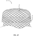
- Figure 22 shows a stentless support structure 10 with a folded end 14, which has been folded back on itself, and a material 42 trapped between the two layers of the fold.
- the material 42 is provided to further improve the paravalvular leak prevention and embolic trapping characteristics of the stentless support structure 10.
- the material 42 could consist of a non-woven material, woven or braided fabric, a polymer or other material.
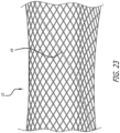
- Figure 23 shows a stentless support structure 10 that includes a fiber 44 that is larger than the rest of the strands comprising the support structure 10.
- Figure 23 demonstrates that strands of different sizes may be used in the braided support structure 10 without significantly affecting the minimum delivery size of the device. Different sized strands may be used in order to improve strength, provide stiffness, create valve attachment points, provide radiopaque markers, and the like.
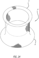
- Figures 24-26 show a stentless support structure 10 that has a first end 12 that has had the unbraided strands trimmed such that they do not extend past the first end 12 of the folded structure 10. This example may be used to create, preserve or enlarge a lumen.
- a prosthetic valve may or may not be attached to this exemplary embodiment.
- FIG. 27 a deployment sequence of an example of the stentless support structure 10 is shown whereby a clear piece of tubing 46 is used to demonstrate a targeted location of a native vessel, such as a native valve.
- a native vessel such as a native valve.
- the delivery catheter 28 is advanced beyond the targeted valve 46 and the stentless support 10 is starting to be ejected from the catheter 28.
- first layer 30 has been fully ejected from the catheter 28, as has much of the second layer 32.
- the second layer 32 has not yet inverted itself into the first layer 30.
- Figures 32-33 the catheter 28 is being advanced to allow the third layer 34 to invert into the second layer 32.
- the angle of Figure 32 shows the relatively low profile created by the first and second layers 30 and 32, and how little resistance to blood flow is presented by the support structure 10.
- Figure 34 the first end 12 has emerged from the catheter 12, and the gathered ends 22 are showing.
- a wireform 24 is attached to some of the gathered ends 22 and is nearly completely deployed from the delivery catheter 28.
- Figures 35-36 the support structure 10 has been completely released from the catheter 28.
- Figure 36 shows the size of the lumen 20 of the support structure 10.
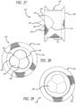
- Figures 37-39 show an example 100 including a mesh support structure 102, a wireform 104 and a valve 106.
- the support structure 102 differs slightly from support structure 10, described previously, as it is constructed from a two individual wires 108.
- the two free ends of the wire are spliced together. As such, there are no free wire ends and the structure can be loaded into a delivery catheter in a single-ply state (not shown).
- the support structure 102 is folded once to form a two-ply device.
- the support structure 102 is preferably formed of a memory alloy such as Nitinol.
- the single-wire construction allows the device to be compressed into an extremely small catheter, such as one sized 16Fr or smaller.
- the support structure gains rigidity by the two-ply deployed configuration, radial strength is a function of a several factors and can thus be varied widely.
- radial strength may be increased by incorporating more folds or layers into the deployed configuration of the support structure 102.
- the three-ply configuration shown in Figures 37-39 is the most preferred configuration because it only has to be folded in on itself twice, making deployment less complicated.
- Support structure 102 is made from a single-wire, and can thus be loaded into a catheter in a single-ply configuration, a larger diameter wire may be used while maintaining a small diameter elongated profile.
- Support structures 102 have been constructed using single wires having diameters between 0.0127 and 0.0254 cm (0.005 and 0.010 inches) in diameter.
- the diameter of the wire is between 0.01778 and 0.02032 cm (0.007 and 0.008 inches).
- strength may be increased by increasing the braid density. A tighter braid will result in a stronger support.
- the strength may be increased by altering the heat setting parameters.
- Super-elastic and shape memory alloys such as Nitinol, attain their deployed shape within the vasculature by being heat set.
- the wires are held in a desired configuration and heated to a predetermined temperature for a predetermined period of time. After the wires cool, they become set to the new configuration. If the wires are later disfigured, they will return to the set configuration upon heating or simply releasing the wires.
- the force with which a super-elastic or shape memory alloy returns to a set configuration can be increased by modifying the temperature at which the configuration is set, or by modifying the period of time the alloy is maintained at the elevated setting temperature.
- Stiffer support structures can be made using the same Nitinol wire by setting the structure at a temperature other than 530°C or by setting the structure at 530°C for a time other than 7 minutes, or both.
- the valve 106 may be any form of prosthetic or harvested biological valve.
- the valve 106 is a valve having three leaflets.
- the valve 106 is sutured or otherwise attached to the wireform 104.
- the valve 106 is cut or constructed to include a skirt portion 112 which continues along the length of the support structure 102 in its deployed configuration.
- Figures 40-46 illustrate the operation of a delivery technique according to the present invention in which the support structure 10 replaces a diseased valve.
- a relatively short delivery catheter 200 is advanced through the chest and heart wall to reach a desired native valve. Once the native valve is reached, the user can deploy and shape the support structure 10 in a manner similar to the previously described methods.
- a mini thoracotomy is performed on a patient, opening up a small passage in the chest between the ribs.
- a path is created from the chest incision, through the intervening tissue layers (e.g., cardial sacks) to the heart 204.
- a heart bypass procedure may also be performed to reduce any complications otherwise caused by creating an incision in the heart 204.
- an incision 207 is created near the lower apex 201 of the heart 204 (i.e., a transapical approach into the heart) to access the left ventricle 203 and ultimately the native aortic valve 208.
- purse-string sutures 202 are sutured around the incision 207 shortly after its creation to minimize blood loss that may otherwise occur from the beating heart 204.
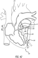
- the support structure 10 is oriented within the catheter 200 to have the first end 12 in a distal position and the second end 14 in a proximal position, allowing the first end 12 of the support structure 10 to be released first into the aorta 210.
- the prosthetic valve 36 (not shown in Figure 42 ) is oriented to open as blood flow passes from the left ventricle 206 into the aorta 210 during a heart beat.
- the support structure 10 is pushed out of the delivery catheter 200 so that the first end 12 deploys into the aorta 210.
- the delivery catheter 200 is moved proximally back through the valve 208 as the support structure 10 continues to be pushed out of the distal end of the catheter.
- the support structure 10 is seen fully deployed so that the second end 14 of the support structure 10 is positioned through the aortic valve 208 and within the left ventricle 206.
- the delivery catheter 200 includes a pull wire 220 positioned through the delivery catheter 200 and within the support structure 10.
- the pull wire 220 includes a distal end coupled to the first end 12 (i.e., the distal end) of the support structure 10 and a proximal end of the pull wire 220 which is accessible to the user at a proximal end of the delivery catheter 200.
- the pull wire 220 When the user is satisfied that the support structure 10 has achieved a desired shape, the pull wire 220 is disconnected from the first end 12 of the support structure 10.
- the pull wire 220 may include different selectively releasable arrangements that allow the user to disconnect or uncouple the distal end of the pull wire 220 at a desired time.
- the pull wire 220 may include selectively releasable jaws such as those seen on the connecting members in the U.S. Provisional Applications Number 60/827373 entitled Delivery Tool For Percutaneous Delivery Of A Prosthesis, filed September 28, 2006 .
- the pull wire 220 may include hooks or detachable adhesives to release the pull wire 220 from the support structure 10.
Description
- There has been a significant movement toward developing and performing cardiovascular surgeries using a percutaneous approach. Through the use of one or more catheters that are introduced through, for example, the femoral artery, tools and devices can be delivered to a desired area in the cardiovascular system to perform many number of complicated procedures that normally otherwise require an invasive surgical procedure. Such approaches greatly reduce the trauma endured by the patient and can significantly reduce recovery periods. The percutaneous approach is particularly attractive as an alternative to performing open-heart surgery.
- Valve replacement surgery provides one example of an area where percutaneous solutions are being developed. A number of diseases result in a thickening, and subsequent immobility or reduced mobility, of heart valve leaflets. Such immobility also may lead to a narrowing, or stenosis, of the passageway through the valve. The increased resistance to blood flow that a stenosed valve presents can eventually lead to heart failure and ultimately death.
- Treating valve stenosis or regurgitation has heretofore involved complete removal of the existing native valve through an open-heart procedure followed by the implantation of a prosthetic valve. Naturally, this is a heavily invasive procedure and inflicts great trauma on the body leading usually to great discomfort and considerable recovery time. It is also a sophisticated procedure that requires great expertise and talent to perform.
- Historically, such valve replacement surgery has been performed using traditional open-heart surgery where the chest is opened, the heart stopped, the patient placed on cardiopulmonary bypass, the native valve excised and the replacement valve attached. On the other hand
US20080221672 discloses a valve prosthesis with rotating arms to anchor the prosthesis.US20080033482 discloses a filter.US5755772 discloses an inversion mechanism in the form of a plug (retainer member) 102 that acts against the end of the tube. As it is pulled, it pushes the end of the tube, causing radial expansion and the end to fold into itself. Once the end folds in and expands, the plug passes through the tube.US20060155366 discloses a stent graft and a method for deploying the stent graft.WO2006/128193 discloses a stentless support structure capable of being at least partly assembled in situ. A proposed percutaneous valve replacement alternative method is disclosed inU.S. Pat. No. 6, 168,614 issued to Andersen et al. In this patent, the prosthetic valve is mounted on a stent that is collapsed to a size that fits within a catheter. The catheter is then inserted into the patient's vasculature and moved so as to position the collapsed stent at the location of the native valve. A deployment mechanism is activated that expands the stent containing the replacement valve against the valve cusps. The expanded structure includes a stent configured to have a valve shape with valve leaflet supports begins to take on the function of the native valve. As a result, a full valve replacement has been achieved but at a significantly reduced physical impact to the patient. - However, this approach has decided shortcomings. One particular drawback with the percutaneous approach disclosed in the Andersen '614 patent is the difficulty in preventing leakage around the perimeter of the new valve after implantation. Since the tissue of the native valve remains within the lumen, there is a strong likelihood that the commissural junctions and fusion points of the valve tissue (as pushed apart and fixed by the stent) will make sealing around the prosthetic valve difficult. In practice, this has often led to severe leakage of blood around the stent apparatus.
- Other drawbacks of the Andersen '614 approach pertain to its reliance on stents as support scaffolding for the prosthetic valve. First, stents can create emboli when they expand. Second, stents are typically not effective at trapping the emboli they dislodge, either during or after deployment. Third, stents do not typically conform to the features of the native lumen in which they are placed, making a prosthetic valve housed within a stent subject to paravalvular leakage. Fourth, stents are subject to a tradeoff between strength and compressibility. Fifth, stents cannot be retrieved once deployed. Sixth, the inclusion of the valve within the stent necessarily increases the collapsed diameter of the stent-valve complex and increases the caliber of the material that must be delivered into the vasculature.
- As to the first drawback, stents usually fall into one of two categories: self-expanding stents and expandable stents. Self-expanding stents are compressed when loaded into a catheter and expand to their original, non-compressed size when released from the catheter. These are typically made of Nitinol. Balloon expandable stents are loaded into a catheter in a compressed but relaxed state. These are typically made from stainless steel or other malleable metals. A balloon is placed within the stent. Upon deployment, the catheter is retracted and the balloon inflated, thereby expanding the stent to a desired size. Both of these stent types exhibit significant force upon expansion. The force is usually strong enough to crack or pop thrombosis, thereby causing pieces of atherosclerotic plaque to dislodge and become emboli. If the stent is being implanted to treat a stenosed vessel, a certain degree of such expansion is desirable. However, if the stent is merely being implanted to displace native valves, less force may be desirable to reduce the chance of creating emboli.
- As to the second drawback, if emboli are created, expanded stents usually have members that are too spaced apart to be effective to trap any dislodged material. Often, secondary precautions must be taken including the use of nets and irrigation ports.
- The third drawback is due to the relative inflexibility of stents. Stents typically rely on the elastic nature of the native vessel to conform around the stent. Stents used to open a restricted vessel do not require a seal between the vessel and the stent. However, when using a stent to displace native valves and house a prosthetic valve, a seal between the stent and the vessel is necessary to prevent paravalvular leakage. Due to the non-conforming nature of stents, this seal is hard to achieve, especially when displacing stenosed valve leaflets.
- The fourth drawback is the tradeoff between compressibility and strength. Stents are made stronger or larger by manufacturing them with thicker members. Stronger stents are thus not as compressible as weaker stents. Most stents suitable for use in a valve are not compressible enough to be placed in a small diameter catheter, such as a 20Fr, 16Fr or even 14Fr catheter. Larger delivery catheters are more difficult to maneuver to a target area and also result in more trauma to the patient.
- The fifth drawback of stents is that they are not easily retrievable. Once deployed, a stent may not be recompressed and drawn back into the catheter for repositioning due to the non-elastic deformation (stainless steel) or the radial force required to maintain the stent in place (Nitinol). Thus, if a physician is unsatisfied with the deployed location or orientation of a stent, there is little he or she can do to correct the problem.
- The sixth drawback listed above is that the combination of the valve within the stent greatly increases the size of the system required to deliver the prosthetic device. As a result, the size of the entry hole into the vasculature is large and often precludes therapy, particularly in children, smaller adults or patients with pre-existing vascular disease.
- It is thus an object of the present invention to address these drawbacks. Specifically, it is an object of the invention to provide a support structure that expands gently, with gradual force, thereby minimizing the generation of emboli.
- It is further an object of the invention to provide a support structure that traps any emboli generated, thereby preventing the emboli from causing damage downstream.
- It is yet another object of the invention to provide a support structure that conforms to the features of the lumen in which it is being deployed, thereby preventing paravalvular leakage.
- It is still another object of the invention to provide a strong support structure capable of being deployed from a very small diameter catheter.
- It is further an object of the invention to provide a support structure that is capable of being retracted back into a delivery catheter and redeployed therefrom.
- It is another object of the invention to provide a device that is delivered with the valve distinctly separated from the inside diameter of the final configuration of the support structure in order to reduce the amount of space required to deliver the device within the vasculature of the patient.
- The present invention is defined by the appended claims only, in particular by the scope of appended independent claims. References to "embodiments" throughout the description which are not under the scope of the appended claims merely represents possible exemplary executions. Specifically, the description of
Figs. 1 to 39 serves the purpose of more clearly understanding the present invention which concept is described in relation toFigs. 40 to 46 . Embodiments provide a tubular mesh support structure for a native lumen that is capable of being delivered via a very small diameter delivery catheter. The tubular mesh is formed one or more fine strands braided together into an elongate tube. The strands may be fibrous, non-fibrous, multifilament, or monofilament. The strands exhibit shape memory such that the elongate tube may be formed into a desired folded shape, then stretched out into a very small diameter, elongated configuration. The small diameter, elongated configuration makes a very small diameter delivery catheter possible. - Upon deployment, the elongated tube is slowly pushed out of the delivery catheter, where it gradually regains its folded, constructed configuration. The tube conforms to the internal geometries of the target vessel. In addition, the braid effectively traps all emboli that may be released from the vessel walls.
- As the tube continues to be pushed from the delivery catheter, it begins to fold in upon itself as it regains its constructed configuration. As it folds in upon itself, the forces exerted by each layer add together, making the structure incrementally stronger. Thus, varying levels of strength may be achieved without changing the elongated diameter of the device.
- Using this folded tube, the valve can be attached such that the valve or other structure (such as a filter) in its elongated configuration within the delivery catheter does not reside within the elongated tube, but on deployment can be positioned in, above or below the tube.
-
-
Figure 1 is a perspective view of an exemplary configuration of an elongate configuration; -
Figure 2 is a side view of an exemplary configuration; -
Figures 3-12 are a sequence of perspective views of an exemplary configuration being deployed from a delivery catheter; -
Figure 13 is a perspective view of an exemplary configuration; -
Figure 14 is a first end view of the concept ofFigure 13 ; -
Figure 15 is a second end view of the concept ofFigure 13 ; -
Figure 16 is a side view of an exemplary configuration; -
Figure 17 is a second end view of the concept ofFigure 16 ; -
Figure 18 is a first end view of the concept ofFigure 16 ; -
Figure 19 is a side view of an exemplary configuration; -
Figure 20 is a first end view of the concept ofFigure 19 ; -
Figure 21 is a second end view of the concept ofFigure 19 ; -
Figure 22 is a partial perspective view of an exemplary configuration; -
Figure 23 is a partial perspective view of an exemplary configuration; -
Figure 24 is a perspective view of an exemplary configuration; -
Figure 25 is a side elevation of the concept ofFigure 24 ; -
Figure 26 is a second end view of the concept ofFigure 24 ; -
Figures 27-36 are a sequence of perspective views of an exemplary configuration being deployed from a delivery catheter against a clear plastic tube representing a native valve; -
Figure 37 is a side elevation view of an exemplary configuration; -
Figure 38 is an end view of a downstream side of the concept ofFigure 37 ; -
Figure 39 is an end view of an upstream side of the concept ofFigure 37 ; -
Figure 40 is a side view of a transapical delivery procedure of a preferred embodiment of the present invention; -
Figure 41 is a cross sectional view of a heart during the transapical delivery procedure ofFigure 40 ; -
Figure 42 is a cross sectional view of a heart during the transapical delivery procedure ofFigure 40 ; -
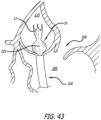
Figure 43 is a magnified view of a support structure during the transapical delivery procedure ofFigure 40 ; -
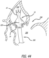
Figure 44 is a magnified view of a support structure during the transapical delivery procedure ofFigure 40 ; -
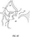
Figure 45 is a magnified view of a support structure during the transapical delivery procedure ofFigure 40 ; and, -
Figure 46 is a cross sectional view of a heart during the transapical delivery procedure ofFigure 40 . - Referring now to the Figures and first to
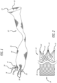
Figure 1 , there is shown astentless support structure 10 of an extended configuration. Thevalve support 10 includes afirst end 12, asecond end 14 and an elongatetubular body 16 extending between thefirst end 12 and thesecond end 14. - The elongate
tubular body 16 is preferably formed from one or a plurality of braidedstrands 18. The braidedstrands 18 are strands of a super-elastic or shape memory material such as Nitinol. The strands are braided to form a tube having acentral lumen 20 passing therethrough. - In one example, the
tubular body 16 is folded in half upon itself such that thesecond end 14 becomes a folded end and thefirst end 12 includes a plurality of unbraided strands. Thetubular body 16 is thus two-ply. The unbraided strands of thefirst end 12 are gathered and joined together to form a plurality of gathered ends 22. The gathered ends 22 may be used as commissural points for attaching a prosthetic valve to thesupport structure 10. (See, e.g.Figure 2 ). Alternatively, as shown inFigure 1 , the gathered ends 22 may be used as attachment points for awireform 24 defining a plurality ofcommissural points 26. - Notably, the commissural points 26 are positioned such that, when a valve is attached to the support structure in the extended configuration, the valve is longitudinally juxtaposed with the support structure rather than being located within the support structure. This juxtaposition allows the
support structure 10 and valve to be packed into a very small catheter without damaging the delicate valve. This longitudinal juxtaposition may be maintained when the support structure assumes a folded or constructed configuration (seeFig. 19 for example), or the valve may become folded within the support structure. -
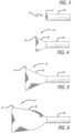
Figures 3-6 show thesecond end 14 emerging from thecatheter 28 to expose afirst layer 30. InFigure 7 , thefirst layer 30 is completely exposed and has assumed its constructed configuration. Notably, thefirst layer 30 contracts longitudinally when fully deployed. Also shown inFigure 7 is asecond layer 32 beginning to emerge from thecatheter 28. As the second layer exits the catheter, the pre-set super-elastic fold inverts the mesh, such that a second, inner layer is formed within the first outer layer. Alternatively, the first layer can be deployed against the wall of the vascular structure (such as an artery, vein, valve or heart muscle). As the second layer exits the catheter, the physician can aid inversion of the mesh my advancing the deployment system. In another example, the mesh support structure can be advanced in the vasculature such that it is deployed in a reverse direction (such as deployment through the apex of the heart ventricle or from the venous system), where the mesh inversion occurs as a result of pulling or retracting the deployment system. - In
Figure 10 , thesecond layer 32 is fully deployed and thethird layer 34 is fully exposed, but has not yet been inverted. Retracting thecatheter 28, relative to thedevice 10, while advancing thecatheter 28 slightly, relative to the target site, causes thethird layer 34 to "pop" inwardly, thereby inverting itself against an inside surface of thesecond layer 32, as seen inFigure 11 . - In
Figure 12 , additional material has been ejected from thecatheter 28 such that thethird layer 34 is fully expanded against the second layer. One skilled in the art will realize that numerous additional layers can be achieved in this manner, and that each layer adds additional radial strength to the resultingsupport structure 10. - Throughout the deployment process, the
stentless support structure 10 emerges from thedelivery catheter 28 gradually. This characteristic also allows thestructure 10 to be pulled back into thedelivery catheter 28, in the event that it is desired to relocate thesupport structure 10. Doing so causes thesupport structure 10 to reacquire its extended configuration. - Having described the mechanics of building a support structure in situ, attention can now be turned to various configurations made possible.
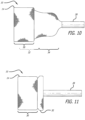
Figures 13-15 show asupport structure 10 havingmany layers 38 and afirst end 12 with numerous gathered ends 22 formed from unbraided strands. Some of the gathered ends 22 are attached to awireform 24 having threecommissural points 26. Aprosthetic valve 36, either harvested or manufactured, is attached to thewireform 24.Figure 15 shows theinternal lumen 20 of thesupport structure 10. -
Figures 16-18 show asupport structure 10 havingfewer layers 38 and awireform 24 with aprosthetic valve 36 attached thereto. The first end 12 (hidden), to which thewireform 24 is attached, has been preformed to fold inwardly upon deployment. Thus, thewireform 24 andprosthetic valve 36, is located in theinner lumen 20 of thesupport structure 10 when thesupport structure 10 is in a constructed configuration. -
Figures 19-21 show asupport structure 10 withseveral layers 38 and afirst end 12 preformed to have a smaller diameter than the rest of the layers and thesecond end 14, which is folded. The terminal ends of the braided strands at thefirst end 12 have not been formed into gathered ends. Rather, thewireform 24 is attached to the braids. Theprosthetic valve 36 is attached to thewireform 24 and has skirtingtissue 40, which is placed around the outside of theend 12. The skirtingtissue 40 may be adhered to thefirst end 12. -
Figure 22 shows astentless support structure 10 with a foldedend 14, which has been folded back on itself, and a material 42 trapped between the two layers of the fold. Thematerial 42 is provided to further improve the paravalvular leak prevention and embolic trapping characteristics of thestentless support structure 10. Thematerial 42 could consist of a non-woven material, woven or braided fabric, a polymer or other material. -
Figure 23 shows astentless support structure 10 that includes afiber 44 that is larger than the rest of the strands comprising thesupport structure 10. Thus,Figure 23 demonstrates that strands of different sizes may be used in thebraided support structure 10 without significantly affecting the minimum delivery size of the device. Different sized strands may be used in order to improve strength, provide stiffness, create valve attachment points, provide radiopaque markers, and the like. -
Figures 24-26 show astentless support structure 10 that has afirst end 12 that has had the unbraided strands trimmed such that they do not extend past thefirst end 12 of the foldedstructure 10. This example may be used to create, preserve or enlarge a lumen. A prosthetic valve may or may not be attached to this exemplary embodiment. - Turning now to
Figures 27-36 , a deployment sequence of an example of thestentless support structure 10 is shown whereby a clear piece oftubing 46 is used to demonstrate a targeted location of a native vessel, such as a native valve. InFigure 27 , thedelivery catheter 28 is advanced beyond the targetedvalve 46 and thestentless support 10 is starting to be ejected from thecatheter 28. - In
Figure 28 , enough of thestentless support 10 has been ejected that the second, foldedend 14 has begun to curl back on itself slightly, forming acuff 48. InFigure 29 , thecuff 48 is more visible and has assumed its full, deployed shape. Thecuff 48 acts as a catch that a physician can use to visually or tactilely locate the targetedvalve 46 and seat thestentless support 10 thereagainst. The cuff also acts to ensure the entire native lumen through the targetedvalve 46 is now being filtered by thesupport 10. Unlike balloon expandable stents, blood flow is not significantly inhibited by the deployment of thestentless support structure 10. Also shown inFigure 29 is that thefirst layer 30 has been fully ejected from thecatheter 28, as has much of thesecond layer 32. Thefirst layer 30, being very flexible prior to reinforcement by subsequent layers, is able to conform to any shape of the targeted vessel. Thesecond layer 32 has not yet inverted itself into thefirst layer 30. - In
Figure 30 , thefirst layer 30 is deployed, thecuff 48 is acting against thevalve 46, and thesecond layer 32 has been inverted. InFigure 31 , material forming thethird layer 34 is ejected from thecatheter 28 but thethird layer 34 has not yet inverted. - In
Figures 32-33 , thecatheter 28 is being advanced to allow thethird layer 34 to invert into thesecond layer 32. The angle ofFigure 32 shows the relatively low profile created by the first andsecond layers support structure 10. - In
Figure 34 , thefirst end 12 has emerged from thecatheter 12, and the gathered ends 22 are showing. Awireform 24 is attached to some of the gathered ends 22 and is nearly completely deployed from thedelivery catheter 28. InFigures 35-36 , thesupport structure 10 has been completely released from thecatheter 28.Figure 36 shows the size of thelumen 20 of thesupport structure 10. -
Figures 37-39 show an example 100 including amesh support structure 102, awireform 104 and avalve 106. Thesupport structure 102 differs slightly fromsupport structure 10, described previously, as it is constructed from a twoindividual wires 108. Upon completion of the braiding process, the two free ends of the wire are spliced together. As such, there are no free wire ends and the structure can be loaded into a delivery catheter in a single-ply state (not shown). In the deployed state shown in the Figures, thesupport structure 102 is folded once to form a two-ply device. - The
support structure 102 is preferably formed of a memory alloy such as Nitinol. The single-wire construction allows the device to be compressed into an extremely small catheter, such as one sized 16Fr or smaller. Though the support structure gains rigidity by the two-ply deployed configuration, radial strength is a function of a several factors and can thus be varied widely. - First, as with the other examples, radial strength may be increased by incorporating more folds or layers into the deployed configuration of the
support structure 102. The three-ply configuration shown inFigures 37-39 is the most preferred configuration because it only has to be folded in on itself twice, making deployment less complicated. - Second, strength may be increased by using a heavier wire. Because the
support structure 102 is made from a single-wire, and can thus be loaded into a catheter in a single-ply configuration, a larger diameter wire may be used while maintaining a small diameter elongated profile.Support structures 102 have been constructed using single wires having diameters between 0.0127 and 0.0254 cm (0.005 and 0.010 inches) in diameter. Preferably, the diameter of the wire is between 0.01778 and 0.02032 cm (0.007 and 0.008 inches). - Third, strength may be increased by increasing the braid density. A tighter braid will result in a stronger support.
- Fourth, the strength may be increased by altering the heat setting parameters. Super-elastic and shape memory alloys, such as Nitinol, attain their deployed shape within the vasculature by being heat set. The wires are held in a desired configuration and heated to a predetermined temperature for a predetermined period of time. After the wires cool, they become set to the new configuration. If the wires are later disfigured, they will return to the set configuration upon heating or simply releasing the wires. The force with which a super-elastic or shape memory alloy returns to a set configuration can be increased by modifying the temperature at which the configuration is set, or by modifying the period of time the alloy is maintained at the elevated setting temperature. For example, good results have been attained setting a Nitinol support structure at 530°C for 7 minutes. Stiffer support structures can be made using the same Nitinol wire by setting the structure at a temperature other than 530°C or by setting the structure at 530°C for a time other than 7 minutes, or both.
- The
device 100 includes awireform 104, to which avalve 106 is attached. Thewireform 104 form commissural points separated byarcuate portions 110. Thearcuate portions 110 are attached to an inside surface of thesupport structure 102. The commissural points 109 facilitate natural and efficient opening and closing of thevalve 106. Alternatively, the valve commissural points can be attached to an outer surface of the support structure (not shown). - The
valve 106 may be any form of prosthetic or harvested biological valve. Preferably, as shown in the Figures, thevalve 106 is a valve having three leaflets. Thevalve 106 is sutured or otherwise attached to thewireform 104. Preferably, thevalve 106 is cut or constructed to include askirt portion 112 which continues along the length of thesupport structure 102 in its deployed configuration. -
Figures 40-46 illustrate the operation of a delivery technique according to the present invention in which thesupport structure 10 replaces a diseased valve. However, instead of advancing an elongated catheter through a remote vessel to reach a heart valve (e.g., through the femoral artery to the aortic valve), a relativelyshort delivery catheter 200 is advanced through the chest and heart wall to reach a desired native valve. Once the native valve is reached, the user can deploy and shape thesupport structure 10 in a manner similar to the previously described methods. - Turning now to
Figure 40 , a mini thoracotomy is performed on a patient, opening up a small passage in the chest between the ribs. A path is created from the chest incision, through the intervening tissue layers (e.g., cardial sacks) to theheart 204. A heart bypass procedure may also be performed to reduce any complications otherwise caused by creating an incision in theheart 204. - Referring to
Figure 41 , anincision 207 is created near thelower apex 201 of the heart 204 (i.e., a transapical approach into the heart) to access the left ventricle 203 and ultimately the nativeaortic valve 208. Preferably, purse-string sutures 202 are sutured around theincision 207 shortly after its creation to minimize blood loss that may otherwise occur from the beatingheart 204. - A guidewire (not shown) is advanced into the chest, through the
incision 207 into theheart 204. In the present example, a distal end of the guidewire is advanced into theleft ventricle 206 and through the nativeaortic valve 208. As seen inFigures 40 and41 , thedelivery catheter 200 is slid over the guidewire, through the chest, into theincision 207 and through the leftaortic valve 208. - Referring to
Figure 42 , thesupport structure 10 is oriented within thecatheter 200 to have thefirst end 12 in a distal position and thesecond end 14 in a proximal position, allowing thefirst end 12 of thesupport structure 10 to be released first into theaorta 210. In this respect, the prosthetic valve 36 (not shown inFigure 42 ) is oriented to open as blood flow passes from theleft ventricle 206 into theaorta 210 during a heart beat. - It should be noted, however, that the
support structure 10 may be positioned within thedelivery catheter 200 to initially deploy thefirst end 12 or thesecond end 14. The desired orientation will depend, in part, on the direction from which thedelivery catheter 200 approaches the native valve and therefore the location where the delivery catheter enters theheart 204. - Referring to
Figures 42 and43 of the present example, thesupport structure 10 is pushed out of thedelivery catheter 200 so that thefirst end 12 deploys into theaorta 210. Thedelivery catheter 200 is moved proximally back through thevalve 208 as thesupport structure 10 continues to be pushed out of the distal end of the catheter. - Turning to
Figure 44 , thesupport structure 10 is seen fully deployed so that thesecond end 14 of thesupport structure 10 is positioned through theaortic valve 208 and within theleft ventricle 206. As seen in this figure, thedelivery catheter 200 includes apull wire 220 positioned through thedelivery catheter 200 and within thesupport structure 10. Thepull wire 220 includes a distal end coupled to the first end 12 (i.e., the distal end) of thesupport structure 10 and a proximal end of thepull wire 220 which is accessible to the user at a proximal end of thedelivery catheter 200. - Once the
support structure 10 is deployed to a desired position, such as that seen inFigure 44 , the user moves thepull wire 220 in a proximal direction, causing thefirst end 12 of thesupport structure 10 to invert or fold back on itself.Figures 45 and46 illustrate an example inverted conformation of thesupport structure 10 in which thefirst end 12 moves within the center passage of thesupport structure 10. - When the user is satisfied that the
support structure 10 has achieved a desired shape, thepull wire 220 is disconnected from thefirst end 12 of thesupport structure 10. Thepull wire 220 may include different selectively releasable arrangements that allow the user to disconnect or uncouple the distal end of thepull wire 220 at a desired time. For example, thepull wire 220 may include selectively releasable jaws such as those seen on the connecting members in theU.S. Provisional Applications Number 60/827373 entitled Delivery Tool For Percutaneous Delivery Of A Prosthesis, filed September 28, 2006 pull wire 220 may include hooks or detachable adhesives to release thepull wire 220 from thesupport structure 10. - Finally, as seen in
Figure 46 , the user removes thedelivery catheter 200 and the guidewire from theheart 204 and fully closes theincision 207 with the purse string sutures 202. Any remaining incisions in the patient's chest are closed and the procedure is complete. - Although the invention has been described in terms of particular embodiments and applications, one of ordinary skill in the art, in light of this teaching, can generate additional embodiments and modifications without departing from or exceeding the scope of the claimed invention, which is defined by the claims. Accordingly, it is to be understood that the drawings and descriptions herein are offered by way of example to facilitate comprehension of the invention and should not be construed to limit the scope thereof, which is defined by the claims.
Claims (6)
- A system for implanting an invertible support structure (10) for replacing a native heart valve, comprising:a delivery catheter (200) containing the invertible support structure (10) in an unfolded, elongated state;an inversion mechanism passing through said delivery catheter (200) and releasably connected to said invertible support structure (10), wherein said inversion mechanism comprises a wire (220) positioned through the delivery catheter (200) and within the invertible support structure (10);wherein the invertible support structure (10) comprises a distal end (12), a proximal end (14), an elongate tubular body (16) having a center passage and extending between the distal end (12) and the proximal end, and a prosthetic valve (36; 106) attached to the distal end (12) of the support structure (10), wherein said wire (220) includes a distal end coupled to the distal end (12) of the support structure (10) and a proximal end accessible at a proximal end of the delivery catheter (200); andwherein said inversion mechanism is usable to initiate inversion of said invertible support structure (10) during delivery by acting on the distal end (12) of said invertible support structure (10); and whereinthe distal end (12) of said invertible support structure (10) is configured to be inverted by moving the wire (220) in a proximal direction causing the distal end (12) of the invertible support structure (10) to fold back on itself.
- The system of claim 1 wherein said inversion mechanism passes at least partially through said support structure (10).
- The system of claim 1 wherein said inversion mechanism is releasably connected to said invertible support structure (10) distal of a preformed fold formed in said support structure (10).
- The system of claim 3 wherein said inversion mechanism is releasably connected to the distal end (12) of said support structure (10).
- The system of claim 3 wherein said support structure (10) comprises two axially spaced preformed folds and said inversion mechanism is releasably connected to said invertible support structure (10) near a distal-most preformed fold.
- The system of claim 4 wherein said preformed folds cause said support structure (10) to form a folded structure, upon inversion, having three plies in at some point along an axial length of said folded structure.
Applications Claiming Priority (2)
| Application Number | Priority Date | Filing Date | Title |
|---|---|---|---|
| US33320010P | 2010-05-10 | 2010-05-10 | |
| PCT/US2011/035983 WO2011143263A2 (en) | 2010-05-10 | 2011-05-10 | Stentless support structure |
Publications (3)
| Publication Number | Publication Date |
|---|---|
| EP2569043A2 EP2569043A2 (en) | 2013-03-20 |
| EP2569043A4 EP2569043A4 (en) | 2017-06-07 |
| EP2569043B1 true EP2569043B1 (en) | 2023-12-13 |
Family
ID=44914948
Family Applications (1)
| Application Number | Title | Priority Date | Filing Date |
|---|---|---|---|
| EP11781175.2A Active EP2569043B1 (en) | 2010-05-10 | 2011-05-10 | Stentless support structure |
Country Status (8)
| Country | Link |
|---|---|
| US (5) | US9089423B2 (en) |
| EP (1) | EP2569043B1 (en) |
| JP (4) | JP5827991B2 (en) |
| CN (1) | CN103124537B (en) |
| AU (1) | AU2011250971B2 (en) |
| CA (1) | CA2798711C (en) |
| IL (2) | IL222941A (en) |
| WO (1) | WO2011143263A2 (en) |
Families Citing this family (88)
| Publication number | Priority date | Publication date | Assignee | Title |
|---|---|---|---|---|
| US8974523B2 (en) | 2005-05-27 | 2015-03-10 | Hlt, Inc. | Stentless support structure |
| US8870950B2 (en) | 2009-12-08 | 2014-10-28 | Mitral Tech Ltd. | Rotation-based anchoring of an implant |
| US8961596B2 (en) | 2010-01-22 | 2015-02-24 | 4Tech Inc. | Method and apparatus for tricuspid valve repair using tension |
| US10058323B2 (en) | 2010-01-22 | 2018-08-28 | 4 Tech Inc. | Tricuspid valve repair using tension |
| US8475525B2 (en) | 2010-01-22 | 2013-07-02 | 4Tech Inc. | Tricuspid valve repair using tension |
| US9307980B2 (en) | 2010-01-22 | 2016-04-12 | 4Tech Inc. | Tricuspid valve repair using tension |
| WO2011111047A2 (en) | 2010-03-10 | 2011-09-15 | Mitraltech Ltd. | Prosthetic mitral valve with tissue anchors |
| WO2011143263A2 (en) | 2010-05-10 | 2011-11-17 | Heart Leaflet Technologies, Inc. | Stentless support structure |
| US9763657B2 (en) | 2010-07-21 | 2017-09-19 | Mitraltech Ltd. | Techniques for percutaneous mitral valve replacement and sealing |
| US8992604B2 (en) | 2010-07-21 | 2015-03-31 | Mitraltech Ltd. | Techniques for percutaneous mitral valve replacement and sealing |
| US11653910B2 (en) | 2010-07-21 | 2023-05-23 | Cardiovalve Ltd. | Helical anchor implantation |
| US9132009B2 (en) | 2010-07-21 | 2015-09-15 | Mitraltech Ltd. | Guide wires with commissural anchors to advance a prosthetic valve |
| US9522064B2 (en) | 2011-05-16 | 2016-12-20 | Hlt, Inc. | Inversion delivery device and method for a prosthesis |
| EP3424468A1 (en) | 2011-07-21 | 2019-01-09 | 4Tech Inc. | Apparatus for tricuspid valve repair using tension |
| WO2013021374A2 (en) | 2011-08-05 | 2013-02-14 | Mitraltech Ltd. | Techniques for percutaneous mitral valve replacement and sealing |
| US20140324164A1 (en) | 2011-08-05 | 2014-10-30 | Mitraltech Ltd. | Techniques for percutaneous mitral valve replacement and sealing |
| US8852272B2 (en) | 2011-08-05 | 2014-10-07 | Mitraltech Ltd. | Techniques for percutaneous mitral valve replacement and sealing |
| EP3417813B1 (en) | 2011-08-05 | 2020-05-13 | Cardiovalve Ltd | Percutaneous mitral valve replacement |
| CA3051684C (en) | 2011-12-06 | 2020-06-16 | Aortic Innovations Llc | Device for endovascular aortic repair and method of using the same |
| AU2013214782B2 (en) * | 2012-02-01 | 2017-03-09 | Hlt, Inc. | Invertible tissue valve and method |
| EP2849677A4 (en) * | 2012-05-16 | 2015-07-15 | Hlt Inc | Inversion delivery and method for a prosthesis |
| US8961594B2 (en) | 2012-05-31 | 2015-02-24 | 4Tech Inc. | Heart valve repair system |
| US9883941B2 (en) | 2012-06-19 | 2018-02-06 | Boston Scientific Scimed, Inc. | Replacement heart valve |
| US9232995B2 (en) | 2013-01-08 | 2016-01-12 | Medtronic, Inc. | Valve prosthesis and method for delivery |
| DE102012107465A1 (en) | 2012-08-15 | 2014-05-22 | Pfm Medical Ag | Implantable device for use in the human and / or animal body for replacement of an organ flap |
| US9066801B2 (en) | 2013-01-08 | 2015-06-30 | Medtronic, Inc. | Valve prosthesis and method for delivery |
| EP2943132B1 (en) | 2013-01-09 | 2018-03-28 | 4Tech Inc. | Soft tissue anchors |
| ES2934670T3 (en) | 2013-01-24 | 2023-02-23 | Cardiovalve Ltd | Ventricularly Anchored Prosthetic Valves |
| US10561509B2 (en) | 2013-03-13 | 2020-02-18 | DePuy Synthes Products, Inc. | Braided stent with expansion ring and method of delivery |
| JP6329570B2 (en) | 2013-03-14 | 2018-05-23 | 4テック インコーポレイテッド | Stent with tether interface |
| WO2014144020A1 (en) * | 2013-03-15 | 2014-09-18 | Hlt, Inc. | Low-profile prosthetic valve structure |
| WO2014204807A1 (en) | 2013-06-19 | 2014-12-24 | Aga Medical Corporation | Collapsible valve having paravalvular leak protection |
| US10052095B2 (en) | 2013-10-30 | 2018-08-21 | 4Tech Inc. | Multiple anchoring-point tension system |
| US10022114B2 (en) | 2013-10-30 | 2018-07-17 | 4Tech Inc. | Percutaneous tether locking |
| WO2015065910A2 (en) * | 2013-10-30 | 2015-05-07 | The Regents Of The University Of Michigan | System and method to limit cerebral ischemia |
| WO2015063580A2 (en) | 2013-10-30 | 2015-05-07 | 4Tech Inc. | Multiple anchoring-point tension system |
| EP2896387A1 (en) * | 2014-01-20 | 2015-07-22 | Mitricares | Heart valve anchoring device |
| CN106573129B (en) | 2014-06-19 | 2019-09-24 | 4科技有限公司 | Heart tissue is tightened |
| EP3174502B1 (en) | 2014-07-30 | 2022-04-06 | Cardiovalve Ltd | Apparatus for implantation of an articulatable prosthetic valve |
| CA2963135A1 (en) | 2014-10-13 | 2016-04-21 | Hlt, Inc. | Inversion delivery device and method for a prosthesis |
| EP3215197B1 (en) | 2014-11-06 | 2020-10-14 | Medtronic Vascular Inc. | Protected magnesium alloys for bioresorbable stents |
| US9693860B2 (en) * | 2014-12-01 | 2017-07-04 | Medtronic, Inc. | Segmented transcatheter valve prosthesis having an unsupported valve segment |
| JP6717820B2 (en) | 2014-12-02 | 2020-07-08 | 4テック インコーポレイテッド | Eccentric tissue anchor |
| CN107205817B (en) | 2014-12-04 | 2020-04-03 | 爱德华兹生命科学公司 | Percutaneous clamp for repairing heart valve |
| WO2016124235A1 (en) * | 2015-02-04 | 2016-08-11 | Despalle De Béarn Olivier | Luminal endoprosthesis |
| US9974651B2 (en) | 2015-02-05 | 2018-05-22 | Mitral Tech Ltd. | Prosthetic valve with axially-sliding frames |
| CN107205818B (en) | 2015-02-05 | 2019-05-10 | 卡迪尔维尔福股份有限公司 | Artificial valve with the frame that slides axially |
| US20160235525A1 (en) | 2015-02-12 | 2016-08-18 | Medtronic, Inc. | Integrated valve assembly and method of delivering and deploying an integrated valve assembly |
| EP3738551A1 (en) * | 2015-05-14 | 2020-11-18 | Edwards Lifesciences Corporation | Heart valve sealing devices and delivery devices therefor |
| US10226335B2 (en) | 2015-06-22 | 2019-03-12 | Edwards Lifesciences Cardiaq Llc | Actively controllable heart valve implant and method of controlling same |
| FR3043907A1 (en) | 2015-11-23 | 2017-05-26 | Alain Dibie | ASSEMBLY FOR REPLACING THE TRICUSPID ATRIO-VENTRICULAR VALVE |
| CA3006010C (en) | 2015-12-28 | 2023-09-26 | Tendyne Holdings, Inc. | Atrial pocket closures for prosthetic heart valves |
| US10531866B2 (en) | 2016-02-16 | 2020-01-14 | Cardiovalve Ltd. | Techniques for providing a replacement valve and transseptal communication |
| CN107126304A (en) * | 2016-02-26 | 2017-09-05 | 奥利维尔·德斯帕列·德贝恩 | Multilayer intracavity stent |
| US10390944B2 (en) * | 2016-04-13 | 2019-08-27 | Hlt, Inc. | Braided support structure |
| EP3496664B1 (en) | 2016-08-10 | 2021-09-29 | Cardiovalve Ltd | Prosthetic valve with concentric frames |
| USD800908S1 (en) | 2016-08-10 | 2017-10-24 | Mitraltech Ltd. | Prosthetic valve element |
| US10292851B2 (en) | 2016-09-30 | 2019-05-21 | DePuy Synthes Products, Inc. | Self-expanding device delivery apparatus with dual function bump |
| US9994980B2 (en) | 2016-10-14 | 2018-06-12 | Inceptus Medical, Llc | Braiding machine and methods of use |
| US10653523B2 (en) | 2017-01-19 | 2020-05-19 | 4C Medical Technologies, Inc. | Systems, methods and devices for delivery systems, methods and devices for implanting prosthetic heart valves |
| US10561495B2 (en) | 2017-01-24 | 2020-02-18 | 4C Medical Technologies, Inc. | Systems, methods and devices for two-step delivery and implantation of prosthetic heart valve |
| CN110573092B (en) | 2017-02-24 | 2023-04-18 | 因赛普特斯医学有限责任公司 | Vasoocclusive devices and methods |
| US11839539B2 (en) | 2017-05-15 | 2023-12-12 | Edwards Lifesciences Corporation | Valve sealing tissue and mesh structure |
| US20180360602A1 (en) * | 2017-06-14 | 2018-12-20 | 4C Medical Technologies, Inc. | Delivery of heart chamber prosthetic valve implant |
| US10537426B2 (en) | 2017-08-03 | 2020-01-21 | Cardiovalve Ltd. | Prosthetic heart valve |
| US11246704B2 (en) | 2017-08-03 | 2022-02-15 | Cardiovalve Ltd. | Prosthetic heart valve |
| US11793633B2 (en) | 2017-08-03 | 2023-10-24 | Cardiovalve Ltd. | Prosthetic heart valve |
| US10575948B2 (en) | 2017-08-03 | 2020-03-03 | Cardiovalve Ltd. | Prosthetic heart valve |
| US10888421B2 (en) | 2017-09-19 | 2021-01-12 | Cardiovalve Ltd. | Prosthetic heart valve with pouch |
| JP7429187B2 (en) | 2017-10-14 | 2024-02-07 | インセプタス メディカル リミテッド ライアビリティ カンパニー | Braiding machine and usage |
| BR112020007850A2 (en) | 2017-10-19 | 2020-12-01 | Admedus Corporation | heart valve replacement device with reduced suture |
| WO2019079788A1 (en) | 2017-10-20 | 2019-04-25 | Boston Scientific Scimed, Inc. | Heart valve repair implant for treating tricuspid regurgitation |
| GB201720803D0 (en) | 2017-12-13 | 2018-01-24 | Mitraltech Ltd | Prosthetic Valve and delivery tool therefor |
| GB201800399D0 (en) | 2018-01-10 | 2018-02-21 | Mitraltech Ltd | Temperature-control during crimping of an implant |
| US10874513B2 (en) * | 2018-02-12 | 2020-12-29 | 4C Medical Technologies, Inc. | Expandable frames and paravalvular leak mitigation systems for implantable prosthetic heart valve devices |
| EP3793484A4 (en) * | 2018-05-18 | 2022-03-09 | Anteris Technologies Corporation | Inverted heart valve for transcatheter valve replacement |
| BR112020021303A2 (en) | 2018-05-18 | 2021-01-26 | Admedus Corporation | replacement heart valve assembly with a valve loaded distally from a stent |
| AU2019269738A1 (en) | 2018-05-18 | 2020-11-19 | Anteris Technologies Corporation | Heart valve with gathered sealing region |
| AU2019204522A1 (en) * | 2018-07-30 | 2020-02-13 | DePuy Synthes Products, Inc. | Systems and methods of manufacturing and using an expansion ring |
| US10456280B1 (en) | 2018-08-06 | 2019-10-29 | DePuy Synthes Products, Inc. | Systems and methods of using a braided implant |
| US11857441B2 (en) | 2018-09-04 | 2024-01-02 | 4C Medical Technologies, Inc. | Stent loading device |
| US11039944B2 (en) | 2018-12-27 | 2021-06-22 | DePuy Synthes Products, Inc. | Braided stent system with one or more expansion rings |
| US11931253B2 (en) | 2020-01-31 | 2024-03-19 | 4C Medical Technologies, Inc. | Prosthetic heart valve delivery system: ball-slide attachment |
| US20230248513A1 (en) | 2020-07-07 | 2023-08-10 | Anteris Technologies Corporation | Expandable frame for improved hemodynamic performance of transcatheter replacement heart valve |
| US11857417B2 (en) | 2020-08-16 | 2024-01-02 | Trilio Medical Ltd. | Leaflet support |
| US11197755B1 (en) * | 2020-10-28 | 2021-12-14 | Occam Labs LLC | Systems, devices and methods for folded unibody heart valve stents |
| WO2023114659A2 (en) * | 2021-12-17 | 2023-06-22 | Hlt, Inc. | Motorized implant delivery device, implant, loading system, and method of using |
| US11622853B1 (en) | 2022-09-30 | 2023-04-11 | Anteris Technologies Corporation | Prosthetic heart valves |
Family Cites Families (73)
| Publication number | Priority date | Publication date | Assignee | Title |
|---|---|---|---|---|
| JP3628847B2 (en) | 1997-08-18 | 2005-03-16 | 株式会社日立製作所 | Bus switching device, computer, and information processing device |
| US4056854A (en) | 1976-09-28 | 1977-11-08 | The United States Of America As Represented By The Department Of Health, Education And Welfare | Aortic heart valve catheter |
| DK124690D0 (en) | 1990-05-18 | 1990-05-18 | Henning Rud Andersen | FAT PROTECTION FOR IMPLEMENTATION IN THE BODY FOR REPLACEMENT OF NATURAL FLEET AND CATS FOR USE IN IMPLEMENTING A SUCH FAT PROTECTION |
| ATE149323T1 (en) * | 1992-08-06 | 1997-03-15 | Cook William Europ | PROSTHESIS FOR SUPPORTING A BLOOD VESSEL OR A LUMENS OF A HOLLOW ORGAN |
| US6010531A (en) | 1993-02-22 | 2000-01-04 | Heartport, Inc. | Less-invasive devices and methods for cardiac valve surgery |
| GB9312666D0 (en) | 1993-06-18 | 1993-08-04 | Vesely Ivan | Bioprostetic heart valve |
| ES2340142T3 (en) * | 1994-07-08 | 2010-05-31 | Ev3 Inc. | SYSTEM TO CARRY OUT AN INTRAVASCULAR PROCEDURE. |
| US5846261A (en) | 1994-07-08 | 1998-12-08 | Aga Medical Corp. | Percutaneous catheter directed occlusion devices |
| US5755770A (en) | 1995-01-31 | 1998-05-26 | Boston Scientific Corporatiion | Endovascular aortic graft |
| CA2173023C (en) | 1995-03-30 | 2001-08-28 | David Kupiecki | Liquid coils with secondary shape |
| US5709713A (en) | 1995-03-31 | 1998-01-20 | Cardiovascular Concepts, Inc. | Radially expansible vascular prosthesis having reversible and other locking structures |
| WO1997025002A1 (en) | 1996-01-05 | 1997-07-17 | Medtronic, Inc. | Expansible endoluminal prostheses |
| US5716370A (en) | 1996-02-23 | 1998-02-10 | Williamson, Iv; Warren | Means for replacing a heart valve in a minimally invasive manner |
| US6402780B2 (en) | 1996-02-23 | 2002-06-11 | Cardiovascular Technologies, L.L.C. | Means and method of replacing a heart valve in a minimally invasive manner |
| US6592617B2 (en) | 1996-04-30 | 2003-07-15 | Boston Scientific Scimed, Inc. | Three-dimensional braided covered stent |
| US6007544A (en) | 1996-06-14 | 1999-12-28 | Beth Israel Deaconess Medical Center | Catheter apparatus having an improved shape-memory alloy cuff and inflatable on-demand balloon for creating a bypass graft in-vivo |
| JP2001505807A (en) | 1996-12-10 | 2001-05-08 | パーデュー・リサーチ・ファウンデーション | Artificial vascular valve |
| US6015431A (en) | 1996-12-23 | 2000-01-18 | Prograft Medical, Inc. | Endolumenal stent-graft with leak-resistant seal |
| EP0850607A1 (en) | 1996-12-31 | 1998-07-01 | Cordis Corporation | Valve prosthesis for implantation in body channels |
| WO1998039053A1 (en) * | 1997-03-06 | 1998-09-11 | Scimed Life Systems, Inc. | Distal protection device and method |
| US5984959A (en) | 1997-09-19 | 1999-11-16 | United States Surgical | Heart valve replacement tools and procedures |
| US6168788B1 (en) | 1997-09-26 | 2001-01-02 | Leon Wortham | Fibrin glue without fibrinogen and biosealant compositions and methods |
| US20040260333A1 (en) | 1997-11-12 | 2004-12-23 | Dubrul William R. | Medical device and method |
| EP1032328A1 (en) | 1997-11-25 | 2000-09-06 | Triad Vascular Systems Inc. | Layered endovascular graft |
| CA2261488A1 (en) | 1999-01-21 | 2000-07-21 | Anthony Paolitto | Transabdominal device for performing closed-chest cardiac surgery |
| EP1143882B1 (en) | 1999-01-26 | 2007-12-05 | Edwards Lifesciences Corporation | Flexible heart valve |
| US6524339B1 (en) | 1999-01-27 | 2003-02-25 | David H. Adams | Cryopreserved homografts and other stentless bioprosthetic heart valves having natural tissue sewing rings |
| US6425916B1 (en) | 1999-02-10 | 2002-07-30 | Michi E. Garrison | Methods and devices for implanting cardiac valves |
| CA2364136A1 (en) | 1999-03-08 | 2000-09-14 | Microvena Corporation | Minimally invasive medical device deployment and retrieval system |
| US6287335B1 (en) * | 1999-04-26 | 2001-09-11 | William J. Drasler | Intravascular folded tubular endoprosthesis |
| US6245107B1 (en) | 1999-05-28 | 2001-06-12 | Bret A. Ferree | Methods and apparatus for treating disc herniation |
| ATE256436T1 (en) * | 1999-08-27 | 2004-01-15 | Ev3 Inc | SLIDING VASCULAR FILTER |
| US6458153B1 (en) | 1999-12-31 | 2002-10-01 | Abps Venture One, Ltd. | Endoluminal cardiac and venous valve prostheses and methods of manufacture and delivery thereof |
| US6837886B2 (en) * | 2000-05-03 | 2005-01-04 | C.R. Bard, Inc. | Apparatus and methods for mapping and ablation in electrophysiology procedures |
| EP1401358B1 (en) | 2000-06-30 | 2016-08-17 | Medtronic, Inc. | Apparatus for performing a procedure on a cardiac valve |
| IL137326A0 (en) | 2000-07-17 | 2001-07-24 | Mind Guard Ltd | Implantable braided stroke preventing device and method of manufacturing |
| US7510572B2 (en) | 2000-09-12 | 2009-03-31 | Shlomo Gabbay | Implantation system for delivery of a heart valve prosthesis |
| US20060142848A1 (en) | 2000-09-12 | 2006-06-29 | Shlomo Gabbay | Extra-anatomic aortic valve placement |
| WO2002047539A2 (en) | 2000-12-15 | 2002-06-20 | Viacor, Inc. | Apparatus and method for replacing aortic valve |
| US6540773B2 (en) | 2001-07-03 | 2003-04-01 | Scimed Life Systems, Inc. | Low profile, high stretch knit prosthetic device |
| US7252681B2 (en) | 2002-02-14 | 2007-08-07 | St. Medical, Inc. | Heart valve structures |
| US7331993B2 (en) | 2002-05-03 | 2008-02-19 | The General Hospital Corporation | Involuted endovascular valve and method of construction |
| US7001425B2 (en) | 2002-11-15 | 2006-02-21 | Scimed Life Systems, Inc. | Braided stent method for its manufacture |
| US7524332B2 (en) | 2003-03-17 | 2009-04-28 | Cook Incorporated | Vascular valve with removable support component |
| GB0316778D0 (en) | 2003-07-17 | 2003-08-20 | Mars Inc | Semi-automatic beverage making apparatus |
| US20050075720A1 (en) | 2003-10-06 | 2005-04-07 | Nguyen Tuoc Tan | Minimally invasive valve replacement system |
| US10219899B2 (en) | 2004-04-23 | 2019-03-05 | Medtronic 3F Therapeutics, Inc. | Cardiac valve replacement systems |
| US7445631B2 (en) * | 2003-12-23 | 2008-11-04 | Sadra Medical, Inc. | Methods and apparatus for endovascularly replacing a patient's heart valve |
| US8052749B2 (en) | 2003-12-23 | 2011-11-08 | Sadra Medical, Inc. | Methods and apparatus for endovascular heart valve replacement comprising tissue grasping elements |
| US7780725B2 (en) | 2004-06-16 | 2010-08-24 | Sadra Medical, Inc. | Everting heart valve |
| US20050137691A1 (en) | 2003-12-23 | 2005-06-23 | Sadra Medical | Two piece heart valve and anchor |
| US20050137686A1 (en) * | 2003-12-23 | 2005-06-23 | Sadra Medical, A Delaware Corporation | Externally expandable heart valve anchor and method |
| US7329279B2 (en) | 2003-12-23 | 2008-02-12 | Sadra Medical, Inc. | Methods and apparatus for endovascularly replacing a patient's heart valve |
| US8777974B2 (en) * | 2004-03-19 | 2014-07-15 | Aga Medical Corporation | Multi-layer braided structures for occluding vascular defects |
| WO2005096993A1 (en) | 2004-03-31 | 2005-10-20 | Med Institute, Inc. | Endoluminal graft with a prosthetic valve |
| WO2005107650A2 (en) * | 2004-05-05 | 2005-11-17 | Direct Flow Medical, Inc. | Unstented heart valve with formed in place support structure |
| CA2583591C (en) | 2004-10-02 | 2018-10-30 | Christoph Hans Huber | Methods and devices for repair or replacement of heart valves or adjacent tissue without the need for full cardiopulmonary support |
| US20060167468A1 (en) | 2004-11-12 | 2006-07-27 | Shlomo Gabbay | Implantation system and method for loading an implanter with a prosthesis |
| WO2006054107A2 (en) | 2004-11-19 | 2006-05-26 | Medtronic Inc. | Method and apparatus for treatment of cardiac valves |
| US20060155366A1 (en) | 2005-01-10 | 2006-07-13 | Laduca Robert | Apparatus and method for deploying an implantable device within the body |
| US8974523B2 (en) | 2005-05-27 | 2015-03-10 | Hlt, Inc. | Stentless support structure |
| US8663312B2 (en) | 2005-05-27 | 2014-03-04 | Hlt, Inc. | Intravascular cuff |
| JP2009509669A (en) | 2005-09-27 | 2009-03-12 | シネコー・エルエルシー | Transgastric surgery device and procedure |
| DE102005052628B4 (en) | 2005-11-04 | 2014-06-05 | Jenavalve Technology Inc. | Self-expanding, flexible wire mesh with integrated valvular prosthesis for the transvascular heart valve replacement and a system with such a device and a delivery catheter |
| US8052750B2 (en) | 2006-09-19 | 2011-11-08 | Medtronic Ventor Technologies Ltd | Valve prosthesis fixation techniques using sandwiching |
| US8070802B2 (en) | 2007-02-23 | 2011-12-06 | The Trustees Of The University Of Pennsylvania | Mitral valve system |
| EP2698129B1 (en) | 2007-06-04 | 2022-11-09 | St. Jude Medical, LLC | Prosthetic heart valve |
| US9232992B2 (en) * | 2008-07-24 | 2016-01-12 | Aga Medical Corporation | Multi-layered medical device for treating a target site and associated method |
| DK2560580T3 (en) | 2010-04-21 | 2019-08-12 | Medtronic Inc | PROTEST CLAP WITH SEALING ELEMENTS |
| WO2011143263A2 (en) | 2010-05-10 | 2011-11-17 | Heart Leaflet Technologies, Inc. | Stentless support structure |
| US8696737B2 (en) | 2010-08-11 | 2014-04-15 | Hlt, Inc. | Reinforced commissural support structure |
| US8845720B2 (en) | 2010-09-27 | 2014-09-30 | Edwards Lifesciences Corporation | Prosthetic heart valve frame with flexible commissures |
| AU2013214782B2 (en) | 2012-02-01 | 2017-03-09 | Hlt, Inc. | Invertible tissue valve and method |
-
2011
- 2011-05-10 WO PCT/US2011/035983 patent/WO2011143263A2/en active Application Filing
- 2011-05-10 CN CN201180034181.4A patent/CN103124537B/en active Active
- 2011-05-10 CA CA2798711A patent/CA2798711C/en not_active Expired - Fee Related
- 2011-05-10 US US13/104,866 patent/US9089423B2/en active Active
- 2011-05-10 JP JP2013510262A patent/JP5827991B2/en active Active
- 2011-05-10 EP EP11781175.2A patent/EP2569043B1/en active Active
- 2011-05-10 AU AU2011250971A patent/AU2011250971B2/en not_active Ceased
-
2012
- 2012-11-08 IL IL222941A patent/IL222941A/en active IP Right Grant
-
2013
- 2013-03-15 US US13/834,135 patent/US9439761B2/en active Active - Reinstated
-
2015
- 2015-07-01 US US14/789,875 patent/US10022221B2/en active Active
- 2015-10-19 JP JP2015205588A patent/JP6067084B2/en not_active Expired - Fee Related
-
2016
- 2016-08-24 IL IL247468A patent/IL247468A0/en unknown
- 2016-08-24 US US15/246,108 patent/US9827095B2/en active Active
- 2016-12-20 JP JP2016246311A patent/JP6294950B2/en active Active
-
2017
- 2017-10-09 US US15/728,006 patent/US10646337B2/en active Active
-
2018
- 2018-02-16 JP JP2018025978A patent/JP2018134404A/en active Pending
Also Published As
| Publication number | Publication date |
|---|---|
| US9439761B2 (en) | 2016-09-13 |
| EP2569043A4 (en) | 2017-06-07 |
| JP6067084B2 (en) | 2017-01-25 |
| JP2017094110A (en) | 2017-06-01 |
| JP6294950B2 (en) | 2018-03-14 |
| IL247468A0 (en) | 2016-11-30 |
| US9089423B2 (en) | 2015-07-28 |
| WO2011143263A2 (en) | 2011-11-17 |
| CA2798711C (en) | 2019-08-27 |
| CN103124537B (en) | 2015-08-26 |
| JP5827991B2 (en) | 2015-12-02 |
| CA2798711A1 (en) | 2011-11-17 |
| US20130204357A1 (en) | 2013-08-08 |
| US10022221B2 (en) | 2018-07-17 |
| US9827095B2 (en) | 2017-11-28 |
| JP2013528068A (en) | 2013-07-08 |
| JP2018134404A (en) | 2018-08-30 |
| US10646337B2 (en) | 2020-05-12 |
| US20160095702A1 (en) | 2016-04-07 |
| US20180028312A1 (en) | 2018-02-01 |
| AU2011250971A1 (en) | 2012-12-06 |
| IL222941A0 (en) | 2012-12-31 |
| IL222941A (en) | 2016-09-29 |
| CN103124537A (en) | 2013-05-29 |
| US20160361165A1 (en) | 2016-12-15 |
| WO2011143263A3 (en) | 2013-01-24 |
| US20120065728A1 (en) | 2012-03-15 |
| JP2016010731A (en) | 2016-01-21 |
| EP2569043A2 (en) | 2013-03-20 |
| AU2011250971B2 (en) | 2015-05-07 |
Similar Documents
| Publication | Publication Date | Title |
|---|---|---|
| US10646337B2 (en) | Stentless support structure | |
| US20210322157A1 (en) | Stentless Support Structure | |
| AU2013213684B2 (en) | Stentless support structure | |
| AU2011265440B2 (en) | Stentless support structure | |
| AU2015224527A1 (en) | Stentless support structure |
Legal Events
| Date | Code | Title | Description |
|---|---|---|---|
| PUAI | Public reference made under article 153(3) epc to a published international application that has entered the european phase |
Free format text: ORIGINAL CODE: 0009012 |
|
| 17P | Request for examination filed |
Effective date: 20121108 |
|
| AK | Designated contracting states |
Kind code of ref document: A2 Designated state(s): AL AT BE BG CH CY CZ DE DK EE ES FI FR GB GR HR HU IE IS IT LI LT LU LV MC MK MT NL NO PL PT RO RS SE SI SK SM TR |
|
| DAX | Request for extension of the european patent (deleted) | ||
| RAP1 | Party data changed (applicant data changed or rights of an application transferred) |
Owner name: HLT, INC. |
|
| A4 | Supplementary search report drawn up and despatched |
Effective date: 20170509 |
|
| RIC1 | Information provided on ipc code assigned before grant |
Ipc: A61F 2/24 20060101AFI20170502BHEP |
|
| STAA | Information on the status of an ep patent application or granted ep patent |
Free format text: STATUS: EXAMINATION IS IN PROGRESS |
|
| 17Q | First examination report despatched |
Effective date: 20200527 |
|
| STAA | Information on the status of an ep patent application or granted ep patent |
Free format text: STATUS: EXAMINATION IS IN PROGRESS |
|
| RAP1 | Party data changed (applicant data changed or rights of an application transferred) |
Owner name: EDWARDS LIFESCIENCES CORPORATION |
|
| GRAP | Despatch of communication of intention to grant a patent |
Free format text: ORIGINAL CODE: EPIDOSNIGR1 |
|
| STAA | Information on the status of an ep patent application or granted ep patent |
Free format text: STATUS: GRANT OF PATENT IS INTENDED |
|
| INTG | Intention to grant announced |
Effective date: 20230623 |
|
| P01 | Opt-out of the competence of the unified patent court (upc) registered |
Effective date: 20230830 |
|
| GRAS | Grant fee paid |
Free format text: ORIGINAL CODE: EPIDOSNIGR3 |
|
| GRAA | (expected) grant |
Free format text: ORIGINAL CODE: 0009210 |
|
| STAA | Information on the status of an ep patent application or granted ep patent |
Free format text: STATUS: THE PATENT HAS BEEN GRANTED |
|
| AK | Designated contracting states |
Kind code of ref document: B1 Designated state(s): AL AT BE BG CH CY CZ DE DK EE ES FI FR GB GR HR HU IE IS IT LI LT LU LV MC MK MT NL NO PL PT RO RS SE SI SK SM TR |
|
| REG | Reference to a national code |
Ref country code: GB Ref legal event code: FG4D |
|
| RIN1 | Information on inventor provided before grant (corrected) |
Inventor name: BANICK, CHRISTOPHER, M. Inventor name: WILSON, ROBERT, FOSTER Inventor name: THILL, GARY, A. Inventor name: GAINOR, JOHN |
|
| REG | Reference to a national code |
Ref country code: CH Ref legal event code: EP |
|
| REG | Reference to a national code |
Ref country code: DE Ref legal event code: R096 Ref document number: 602011074466 Country of ref document: DE |
|
| REG | Reference to a national code |
Ref country code: IE Ref legal event code: FG4D |
|
| PG25 | Lapsed in a contracting state [announced via postgrant information from national office to epo] |
Ref country code: GR Free format text: LAPSE BECAUSE OF FAILURE TO SUBMIT A TRANSLATION OF THE DESCRIPTION OR TO PAY THE FEE WITHIN THE PRESCRIBED TIME-LIMIT Effective date: 20240314 |
|
| REG | Reference to a national code |
Ref country code: LT Ref legal event code: MG9D |
|
| PG25 | Lapsed in a contracting state [announced via postgrant information from national office to epo] |
Ref country code: LT Free format text: LAPSE BECAUSE OF FAILURE TO SUBMIT A TRANSLATION OF THE DESCRIPTION OR TO PAY THE FEE WITHIN THE PRESCRIBED TIME-LIMIT Effective date: 20231213 |