EP2568076B1 - Laundry dryer - Google Patents
Laundry dryer Download PDFInfo
- Publication number
- EP2568076B1 EP2568076B1 EP12182616.8A EP12182616A EP2568076B1 EP 2568076 B1 EP2568076 B1 EP 2568076B1 EP 12182616 A EP12182616 A EP 12182616A EP 2568076 B1 EP2568076 B1 EP 2568076B1
- Authority
- EP
- European Patent Office
- Prior art keywords
- integrated connection
- removable
- sump
- spring
- tumble dryer
- Prior art date
- Legal status (The legal status is an assumption and is not a legal conclusion. Google has not performed a legal analysis and makes no representation as to the accuracy of the status listed.)
- Not-in-force
Links
- 239000007788 liquid Substances 0.000 claims description 26
- 238000007789 sealing Methods 0.000 claims description 16
- 229910000639 Spring steel Inorganic materials 0.000 claims description 3
- 238000001035 drying Methods 0.000 description 23
- 230000000694 effects Effects 0.000 description 3
- 238000000034 method Methods 0.000 description 3
- XLYOFNOQVPJJNP-UHFFFAOYSA-N water Substances O XLYOFNOQVPJJNP-UHFFFAOYSA-N 0.000 description 3
- 238000009833 condensation Methods 0.000 description 2
- 230000005494 condensation Effects 0.000 description 2
- 210000003746 feather Anatomy 0.000 description 2
- 230000007704 transition Effects 0.000 description 2
- 238000009827 uniform distribution Methods 0.000 description 2
- 230000002411 adverse Effects 0.000 description 1
- 230000001419 dependent effect Effects 0.000 description 1
- 239000012530 fluid Substances 0.000 description 1
- 238000003780 insertion Methods 0.000 description 1
- 238000009434 installation Methods 0.000 description 1
- 230000035515 penetration Effects 0.000 description 1
- 230000002093 peripheral effect Effects 0.000 description 1
Images
Classifications
-
- D—TEXTILES; PAPER
- D06—TREATMENT OF TEXTILES OR THE LIKE; LAUNDERING; FLEXIBLE MATERIALS NOT OTHERWISE PROVIDED FOR
- D06F—LAUNDERING, DRYING, IRONING, PRESSING OR FOLDING TEXTILE ARTICLES
- D06F58/00—Domestic laundry dryers
- D06F58/20—General details of domestic laundry dryers
- D06F58/24—Condensing arrangements
Definitions
- the invention relates to a laundry drying apparatus having a collecting chamber for collecting liquid, with a removable collecting container and with the following further features:
- the removable collecting container has a liquid reservoir for collecting liquid and an integrated, designed as a tube open on both sides connecting channel slidably in a tubular lateral continuation of the removable collecting container along a longitudinal axis of the tubular lateral continuation is arranged.
- the liquid is in particular the drying of laundry caused condensation.
- Laundry drying equipment can be designed as a tumble dryer or as a washer dryer, the term dryer is understood a device by means of which laundry can only be dried, while the term washer dryer means a device washed by means of which laundry except dried (before drying) can be.
- Collecting chamber and collecting container are hydraulically connected to one another in the state of the collecting container inserted into the laundry drying device, so that the condensed water can pass from the collecting chamber to the collecting container.
- the bias voltage is generated by means of a spring, a spring steel part or by means of a bimetal.
- the spring is a helical spring.
- the bias acts centrally on the respective flap, so that there is a uniform distribution of the respective contact pressure occurring.
- the tubular side extension of the removable collecting container comprises a stop member, a stopper and a spring radially embracing the integrated connection channel in a given portion thereof radially integrated between the stopper and one on an outer wall of the integrated connection channel Connecting channel arranged further stop is arranged.
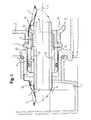
- Fig. 1 shows as parts of a laundry drying apparatus in the form of a longitudinal section the essential parts of a collecting chamber 2 and the essential parts of a removable from the laundry drying device collecting container 3, wherein in this illustration the collecting container 3 is shown as inserted into the laundry drying apparatus.
- its outer border (as far as shown) is drawn with a slightly greater line thickness than the remaining parts of the laundry drying device shown.
- the collecting container 3 has an only marginally illustrated liquid reservoir 33 and an integrated connection channel 1.
- the integrated connection channel 1 is arranged in a tubular lateral continuation 4 of the removable collecting container 3, along a longitudinal axis L of the tubular lateral continuation 4. It is further displaceable along the longitudinal axis L of the tubular lateral continuation 4 in and out of the direction of the collecting chamber 2.
- the collecting container 3 also has a standing under a given bias flap 7, the liquid reservoir 33 in the removed state of the collecting container 3 against the tubular lateral continuation 4 of the collecting container 3 and the integrated connection channel 1 therein hydraulically seals, which will be even closer is explained.
- the collecting chamber 2 also has the collecting chamber 2 a further, also under a given bias flap 7 ', which in the removed state of the collecting container 3 (and thus also the connecting channel 1) hydraulically seals an opening of the collecting chamber 2 released by the removal.
- each one of the two flaps 7, 7 ' not only in a state in which the respective one of the two flaps 7, 7' (yet) does not perform its sealing function (in other words: in the the respective opening is not hydraulically sealed), is under a bias, but that it is still in the state in which it performs their respective intended sealing function, under a (remaining) also given bias.
- This bias can z. B. be generated by means of a spring or a spring steel. But it can also be generated by means of a bimetal.
- the tube-like lateral continuation 4 of the removable collecting container 3 comprises a stop element 9, a stop 51 and a spring 5 which radially surrounds the integrated connecting channel 1 in a given section and which is located between the stop 51 and one on an outer wall of the housing integrated connection channel 1 radially to the integrated connection channel 1 arranged further stop 52 is arranged.
- Fig. 1 the following occurs when removing and reinserting the removable collecting container 3:
- the integrated connection channel 1 is in a respect to the longitudinal axis L so far tared state, as the one end of the integrated connection channel 1 extends into the liquid reservoir 33 of the collecting container 3 and as the opposite end of the integrated connection channel 1 in the Receiving chamber 2 extends into it.
- the two flaps 7 and 7 ' are pushed away upward through the integrated connection channel 1 (eg), as shown Fig. 1 apparent, so that in the collecting chamber 2 existing liquid, whether due to its liquid level or be it due to support measures such.
- the removable collecting container 3 (initially arranged as in the embodiment according to FIG Fig. 1 ) is moved away to the right. Due to the force equilibrium between the two flaps 7, 7 ', which prevails axially along the longitudinal axis L, the removal brings about a quasi-stationary sliding of the integrated connecting channel 1 within the tubular lateral continuation 4 of the removable collecting container 3 to the left, up to its previous local arrangement within the laundry drying apparatus a point at which the stop member 9 abuts the further stop 52 (in Fig. 1 this position of the further stop 52 is shown in dashed lines), wherein the spring 5 expands in length.
- the integrated connecting channel 1 has shifted overall in the direction of the left-hand end of the tubular lateral continuation 4 in such a way that its right end, which so far has penetrated into the liquid reservoir 33, now ends within the tubular lateral continuation 4 at one point, in the Fig. 1 indicated by a dashed line and provided with the reference numeral 6.
- the integrated connection channel 1 remains stationary in this position.
- the integrated connection channel 1 retracts laterally from the collecting chamber 2, so that in succession, the further flap 7 ', which is arranged on the collecting chamber 2, closes and thus prevents liquid flow in the direction of the removable collecting container 3, so that the Collection chamber 2 by means of the further flap 7 'is hydraulically sealed.
- connection channel 1 Due to the inventive design of the integrated connection channel 1 as a straight tube open on both sides this offers the Schwemmgut that is contained in the operation of the laundry dryer in the liquid flowing through it, an optimally low resistance, so that the risk of forming deposits on the connecting channel and / or at the flaps, as described above, is minimized. And even in a case in which deposits should have accumulated in it, this mishap can also be removed relatively easily by manually pushing the integrated connecting channel in the removed state of the removable collecting container into the tubular lateral continuation of the removable collecting container, thereby which opens a flap 7 and then thoroughly flushes through the connecting channel.
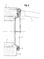
- Fig. 2 shows an advantageous embodiment of a flap 7, but after the other of the two flaps 7, 7 'can be designed: while the spring of the flap 7 is designed as a helical spring 11 which centrally acts on the flap 7 centrally. This results in a uniform distribution of the contact pressure on the flap 7. This is particularly advantageous because the flaps 7 and 7 'according to the invention have a circumferential sealing lip, as in Fig. 2 shown,
Landscapes
- Engineering & Computer Science (AREA)
- Textile Engineering (AREA)
- Detail Structures Of Washing Machines And Dryers (AREA)
Description
Die Erfindung betrifft ein Wäschetrocknungsgerät mit einer Auffangkammer zum Auffangen von Flüssigkeit, mit einem herausnehmbaren Sammelbehälter und mit folgenden weiteren Merkmalen: Der herausnehmbare Sammelbehälter weist ein Flüssigkeitsreservoir zum Sammeln von Flüssigkeit auf sowie einen integrierten, als beidseitig offene Röhre ausgeführten Verbindungskanal, der gleitbar in einer röhrenartigen seitlichen Fortsetzung des herausnehmbaren Sammelbehälters entlang einer Längsachse der röhrenartigen seitlichen Fortsetzung angeordnet ist. Die Flüssigkeit ist insbesondere beim Trocknen von Wäsche entstandenes Kondenswasser.The invention relates to a laundry drying apparatus having a collecting chamber for collecting liquid, with a removable collecting container and with the following further features: The removable collecting container has a liquid reservoir for collecting liquid and an integrated, designed as a tube open on both sides connecting channel slidably in a tubular lateral continuation of the removable collecting container along a longitudinal axis of the tubular lateral continuation is arranged. The liquid is in particular the drying of laundry caused condensation.
Ein solches Wäschetrocknungsgerät geht hervor aus der
Wäschetrocknungsgeräte können als Wäschetrockner oder als Waschtrockner ausgeführt sein, wobei unter dem Begriff Wäschetrockner ein Gerät verstanden wird, mittels dessen Wäsche lediglich getrocknet werden kann, während unter dem Begriff Waschtrockner ein Gerät verstanden wird, mittels dessen Wäsche außer getrocknet auch (vor dem Trocknen) gewaschen werden kann. Auffangkammer und Sammelbehälter sind im in das Wäschetrocknungsgerät eingesetzten Zustand des Sammelbehälters hydraulisch miteinander verbunden, so dass das Kondenswasser von der Auffangkammer zum Sammelbehälter gelangen kann.Laundry drying equipment can be designed as a tumble dryer or as a washer dryer, the term dryer is understood a device by means of which laundry can only be dried, while the term washer dryer means a device washed by means of which laundry except dried (before drying) can be. Collecting chamber and collecting container are hydraulically connected to one another in the state of the collecting container inserted into the laundry drying device, so that the condensed water can pass from the collecting chamber to the collecting container.
Problem bei einem solchen Wäschetrocknungsgerät ist, dass sich im Kondenswasser enthaltenes Schwemmgut wie z. B. Wäscheflusen im Übergangsbereich von der Auffangkammer zum Sammelbehälter anlagern kann, wodurch zum einen bei Bereichen der Auffangkammer wie auch des Sammelbehälters, die bei einem Herausnehmen des Sammelbehälters aus dem Wäschetrocknungsgerät umgehend wasserdicht abgedichtet werden sollen, um ein ggf. auch nur kurzzeitig auftretendes Auslaufen des Kondenswassers zu verhindern, ein Teil dieses Schwemmguts die Dichtwirkung beim Trennen des Sammelbehälters von der Auffangkammer verschlechtern bis aufheben kann. Dies wird häufig auch noch dadurch gefördert, dass der Übergang zwischen Auffangkammer und Sammelbehälter in seinem Verlauf winkelig und/oder verschlungen ausgeführt ist, was bekanntlich einen negativen Einfluß auf die Fließgeschwindigkeit von Flüssigkeiten hat. Eine niedrige Fließgeschwindigkeit wiederum beeinflusst das Fließverhalten des Schwemmguts negativ mit der Folge, dass sich dieses leichter insbesondere an den genannten Problemzonen anlagern kann mit den bereits geschilderten nachteiligen Folgen.Problem with such a laundry dryer is that contained in the condensation alluvial such. B. Wäscheflusen can accumulate in the transition region of the collecting chamber to the collecting container, which on the one hand in areas of the collecting chamber as well as the collecting container, which should be sealed watertight at a removal of the sump from the laundry dryer to a possibly even briefly occurring leakage of the Condensate water to prevent a part of this Schwemmguts the sealing effect when separating the collection of the collecting chamber worsen to pick up. This is often also promoted by the fact that the transition between the collecting chamber and collecting container is executed in its course angular and / or entangled, which is known to have a negative influence on the flow rate of Has fluids. A low flow rate, in turn, negatively influences the flow behavior of the Schwemmguts negative, with the result that this can easily attach particular to the said problem areas with the already described adverse consequences.
Es ist Aufgabe der Erfindung, ein Wäschetrocknungsgerät zu schaffen, bei dem sowohl die Dichtwirkung zwischen seinen einzelnen Teilen als auch der Durchfluss von Kondenswasser zwischen diesen Teilen verbessert sind.It is an object of the invention to provide a clothes drying apparatus in which both the sealing effect between its individual parts and the flow of condensed water between these parts are improved.
Diese Aufgabe wird gemäß den Merkmalen des unabhängigen Patentanspruchs gelöst. Bevorzugte Ausführungsformen sind in abhängigen Patentansprüchen gekennzeichnet und gehen auch aus der nachfolgenden Beschreibung hervor.This object is achieved according to the features of the independent claim. Preferred embodiments are characterized in dependent claims and will become apparent from the following description.
Zur Lösung der Aufgabe angegeben wird deshalb ein Wäschetrocknungsgerät mit einer Auffangkammer zum Auffangen von Flüssigkeit, mit einem herausnehmbaren Sammelbehälter und mit folgenden weiteren Merkmalen:
- der herausnehmbare Sammelbehälter weist ein Flüssigkeitsreservoir zum Sammeln von Flüssigkeit auf sowie einen integrierten, als beidseitig offene Röhre ausgeführten Verbindungskanal, der gleitbar in einer röhrenartigen seitlichen Fortsetzung des herausnehmbaren Sammelbehälters entlang einer Längsachse der röhrenartigen seitlichen Fortsetzung angeordnet ist;
- die röhrenartige seitliche Fortsetzung samt integriertem Verbindungskanal sind bei herausgenommenem Sammelbehälter gegenüber dem Flüssigkeitsreservoir mittels einer auch in dem Zustand, in dem sie ihre abdichtende Funktion ausübt, unter einer gegebenen Vorspannung stehenden und eine umlaufende Dichtlippe aufweisenden Klappe hydraulisch abgedichtet; und
- die Auffangkammer ist bei herausgenommenem Sammelbehälter mittels einer auch in dem Zustand, in dem sie ihre abdichtende Funktion ausübt, unter einer gegebenen Vorspannung stehenden und eine umlaufende Dichtlippe aufweisenden weiteren Klappe hydraulisch abgedichtet,
- wohingegen bei in das Wäschetrocknungsgerät eingesetztem herausnehmbarem Sammelbehälter die Klappen geöffnet sind und über den integrierten Verbindungskanal hinweg eine hydraulisch nutzbare Verbindung zwischen der Auffangkammer und dem herausnehmbaren Sammelbehälter besteht.
- the removable sump comprises a liquid reservoir for collecting liquid and an integral, open-ended tube communicating channel slidably disposed in a tubular lateral continuation of the removable sump along a longitudinal axis of the tubular lateral continuation;
- the tube-like lateral continuation including integrated connecting channel are hydraulically sealed with the collecting container with respect to the liquid reservoir by means of a flap which also has the state in which it performs its sealing function under a given prestressing and having a peripheral sealing lip; and
- the collecting chamber is hydraulically sealed when the collecting container is removed by means of a further flap which is under a given pretension and which has a circumferential sealing lip, even in the state in which it performs its sealing function,
- whereas, when the removable collecting container is inserted into the laundry drying device, the flaps are open and there is a hydraulically usable connection between the collecting chamber and the removable collecting container over the integrated connecting channel.
Bei einer bevorzugten Weiterbildung des erfindungsgemäßen Wäschetrocknungsgeräts ist die Vorspannung mittels einer Feder, eines Federstahlteils oder mittels eines Bimetalls erzeugt.In a preferred embodiment of the laundry drying device according to the invention, the bias voltage is generated by means of a spring, a spring steel part or by means of a bimetal.
Bei einer weiteren bevorzugten Weiterbildung des erfindungsgemäßen Wäschetrocknungsgeräts ist die Feder eine Schraubenfeder.In a further preferred embodiment of the laundry drying device according to the invention, the spring is a helical spring.
Bei noch einer weiteren bevorzugten Weiterbildung des erfindungsgemäßen Wäschetrocknungsgeräts wirkt bei wenigstens einer der beiden Klappen die Vorspannung zentral auf die jeweilige Klappe, so dass sich eine gleichmäßige Verteilung des jeweils auftretenden Anpressdrucks ergibt.In yet another preferred embodiment of the laundry drying device according to the invention, in at least one of the two flaps, the bias acts centrally on the respective flap, so that there is a uniform distribution of the respective contact pressure occurring.
Bei wiederum einer bevorzugten Weiterbildung des erfindungsgemäßen Wäschetrocknungsgeräts umfasst die röhrenartige seitliche Fortsetzung des herausnehmbaren Sammelbehälters ein Stoppelement, einen Anschlag sowie eine den integrierten Verbindungskanal in einem gegebenen Abschnitt desselben radial umfassende Feder, die zwischen dem Anschlag und einem an einer Außenwand des integrierten Verbindungskanals radial zum integrierten Verbindungskanal angeordneten weiteren Anschlag angeordnet ist.In yet another preferred embodiment of the laundry drying apparatus according to the invention, the tubular side extension of the removable collecting container comprises a stop member, a stopper and a spring radially embracing the integrated connection channel in a given portion thereof radially integrated between the stopper and one on an outer wall of the integrated connection channel Connecting channel arranged further stop is arranged.
Ausführungsbeispiele der Erfindung sind nachfolgend anhand der Figuren der beigefügten schematisch ausgeführten Zeichnung näher erläutert. Es zeigen:
-
Fig. 1 Teile einer Auffangkammer und eines Sammelbehälters als Bestandteile eines Wäschetrocknungsgeräts, dargestellt in verschiedenen Einbau- bzw. Ausbauzuständen bzw. -phasen, und -
Fig. 2 eine besondere Ausführungsform eines vorteilhaft gestalteten Details.
-
Fig. 1 Parts of a collecting chamber and a collecting container as components of a laundry drying apparatus, shown in various installation or development states or phases, and -
Fig. 2 a particular embodiment of an advantageously designed detail.
In den Figuren sind gleiche oder funktionsgleiche Elemente jeweils mit den gleichen Bezugszeichen versehen.In the figures, identical or functionally identical elements are each provided with the same reference numerals.
Der Sammelbehälter 3 weist ein nur marginal dargestelltes Flüssigkeitsreservoir 33 sowie einen integrierten Verbindungskanal 1 auf. Der integrierte Verbindungskanal 1 ist in einer röhrenartigen seitlichen Fortsetzung 4 des herausnehmbaren Sammelbehälters 3 angeordnet, und zwar entlang einer Längsachse L der röhrenartigen seitlichen Fortsetzung 4. Er ist weiterhin entlang der Längsachse L der röhrenartigen seitlichen Fortsetzung 4 in und aus Richtung der Auffangkammer 2 verschiebbar.The
Im in das Wäschetrocknungsgerät eingesetzten Zustand des herausnehmbaren Sammelbehälters 3 besteht über das Innere des integrierten Verbindungskanals 1, der beidseitig offen ist, zwischen der Auffangkammer 2 und dem herausnehmbaren Sammelbehälter 3, und insbesondere dessen Flüssigkeitsreservoir 33, eine hydraulisch nutzbare Verbindung, über die in der Auffangkammer 2 sich ansammelnde bzw. angesammelte Flüssigkeit wie z. B. beim Trocknen von Wäsche anfallendes Kondenswasser in das Flüssigkeitsreservoir 33 des Sammelbehälters 3 gelangen bzw. transportiert werden kann.In the state of the
Der Sammelbehälter 3 weist darüber hinaus auch eine unter einer gegebenen Vorspannung stehende Klappe 7 auf, die im herausgenommenen Zustand des Sammelbehälters 3 dessen Flüssigkeitsreservoir 33 gegenüber der röhrenartigen seitlichen Fortsetzung 4 des Sammelbehälters 3 und dem darin befindlichen integrierten Verbindungskanal 1 hydraulisch abdichtet, was nachstehend noch näher erläutert wird. Analog dazu weist auch die Auffangkammer 2 eine weitere, ebenfalls unter einer gegebenen Vorspannung stehende Klappe 7' auf, die im herausgenommenen Zustand des Sammelbehälters 3 (und somit auch des Verbindungskanals 1) eine durch das Herausnehmen frei werdende Öffnung der Auffangkammer 2 hydraulisch abdichtet.The
Dabei ist es hinsichtlich jeder einzelnen der beiden Klappen 7, 7' erfindungsgemäss vorgesehen, dass sie nicht nur in einem Zustand, in dem die jeweilige der beiden Klappen 7, 7' ihre abdichtende Funktion (noch) nicht ausübt (mit anderen Worten: in dem die jeweilige Öffnung nicht hydraulisch abgedichtet ist), sich unter einer Vorspannung befindet, sondern dass sie sich auch in dem Zustand, in dem sie die ihr jeweils zugedachte abdichtende Funktion ausübt, immer noch unter einer (restlichen) ebenfalls gegebenen Vorspannung befindet. Damit kann sie dann nämlich einen gewissen Anpressdruck auf die jeweilige abzudichtende Öffnung ausüben und somit die gewünschte Abdichtung mit höherer Wahrscheinlichkeit sicherstellen. Diese Vorspannung kann z. B. mittels einer Feder oder eines Federstahls erzeugt sein. Sie kann aber auch mittels eines Bimetalls erzeugt sein.It is provided according to the invention with respect to each one of the two flaps 7, 7 ', not only in a state in which the respective one of the two flaps 7, 7' (yet) does not perform its sealing function (in other words: in the the respective opening is not hydraulically sealed), is under a bias, but that it is still in the state in which it performs their respective intended sealing function, under a (remaining) also given bias. Thus, they can then exert a certain contact pressure on the respective opening to be sealed and thus ensure the desired seal with a higher probability. This bias can z. B. be generated by means of a spring or a spring steel. But it can also be generated by means of a bimetal.
Besonders vorteilhaft ist es, wenn die röhrenartige seitliche Fortsetzung 4 des herausnehmbaren Sammelbehälters 3 ein Stoppelement 9, einen Anschlag 51 sowie eine den integrierten Verbindungskanal 1 in einem gegebenen Abschnitt desselben radial umfassende Feder 5 umfasst, die zwischen dem Anschlag 51 und einem an einer Außenwand des integrierten Verbindungskanals 1 radial zum integrierten Verbindungskanal 1 angeordneten weiteren Anschlag 52 angeordnet ist.It is particularly advantageous if the tube-like lateral continuation 4 of the
Bei einer solchen vorteilhaften Anordnung, die in
Bei einem Herausnehmen des herausnehmbaren Sammelbehälters 3 aus dem Wäschetrocknungsgerät geschieht nun Folgendes: der herausnehmbare Sammelbehälter 3 (zunächst angeordnet wie in der Ausführungsform nach
Bei einem Wiedereinsetzen des herausnehmbaren Sammelbehälters 3 in das Wäschetrocknungsgerät drückt bei nach wie vor geschlossener Klappe 7 der integrierte Verbindungskanal 1 zunächst die weitere Klappe 7' auf, wodurch eine hydraulisch nutzbare Verbindung zwischen der Auffangkammer 2 und dem integrierten Verbindungskanal 1 entsteht. Beim Fortsetzen des Wiedereinsetzvorgangs stößt dann der integrierte Verbindungskanal 1 an eine in der Auffangkammer 2 angeordnete Begrenzungsrippe 8 an, die ein weiteres Eindringen des integrierten Verbindungskanals 1 in die Auffangkammer 2 unterbindet. Bei einem weiteren Fortsetzen dieses Vorgangs ändert sich infolgedessen die Position des integrierten Verbindungskanals 1 innerhalb der röhrenartigen seitlichen Fortsetzung 4 des herausnehmbaren Sammelbehälters 3 dahingehend, dass der integrierte Verbindungskanal 1 in Richtung des Flüssigkeitsreservoirs 33 geschoben wird und dabei die Klappe 7 aufstößt. Damit ist die ursprünglich bereits bestehende hydraulisch nutzbare Verbindung zwischen der Auffangkammer 2 und dem herausnehmbaren Sammelbehälter 3 wieder hergestellt; der Wiedereinsetzvorgang ist abgeschlossen.When re-inserting the
Aufgrund der erfindungsgemässen Ausgestaltung des integrierten Verbindungskanals 1 als beidseitig offene, gerade Röhre bietet dieser dem Schwemmgut, das beim Betrieb des Wäschetrocknungsgeräts in der durch ihn fließenden Flüssigkeit enthalten ist, einen optimal geringen Widerstand, so dass die Gefahr des Bildens von Anlagerungen am Verbindungskanal und/oder an den Klappen, wie eingangs geschildert, minimiert ist. Und selbst in einem Fall, in dem sich doch Ablagerungen in ihm angesammelt haben sollten, so lässt sich dieses Malheur ebenfalls relativ einfach beseitigen, indem man den integrierten Verbindungskanal in herausgenommenem Zustand des herausnehmbaren Sammelbehälters in die röhrenartige seitliche Fortsetzung des herausnehmbaren Sammelbehälters manuell hineindrückt, dadurch die eine Klappe 7 öffnet und daraufhin den Verbindungskanal kräftig durchspült.Due to the inventive design of the integrated connection channel 1 as a straight tube open on both sides this offers the Schwemmgut that is contained in the operation of the laundry dryer in the liquid flowing through it, an optimally low resistance, so that the risk of forming deposits on the connecting channel and / or at the flaps, as described above, is minimized. And even in a case in which deposits should have accumulated in it, this mishap can also be removed relatively easily by manually pushing the integrated connecting channel in the removed state of the removable collecting container into the tubular lateral continuation of the removable collecting container, thereby which opens a flap 7 and then thoroughly flushes through the connecting channel.
denn dann kann sich der Anpressdruck gleichmäßig auf die gesamte Dichtlippe 12 verteilen, was wiederum die Dichtwirkung der jeweiligen Klappe 7, 7' optimiert.because then the contact pressure can be evenly distributed over the entire sealing
- 22
- Auffangkammercollecting chamber
- 33
- SammelbehälterClippings
- 3333
- Flüssigkeitsreservoirliquid reservoir
- 11
- integrierter Verbindungskanalintegrated connection channel
- 44
- röhrenartige seitliche Fortsetzungtubular lateral continuation
- LL
- Längsachselongitudinal axis
- 7, 7'7, 7 '
- (weitere) Klappe(further) flap
- 10, 10'10, 10 '
- Federfeather
- 1111
- Schraubenfedercoil spring
- 1212
- Dichtlippesealing lip
- 99
- Stoppelementstop element
- 51, 5251, 52
- (weiterer) Anschlag(further) stop
- 55
- Federfeather
Claims (5)
- Tumble dryer appliance with a collection chamber (2) for collecting liquid, with a removable sump (3) and with the following further features:the removable sump (3) has a liquid reservoir (33) for gathering liquid as well as an integrated connection duct (1) embodied as a tube open at both ends, which is disposed so as to be able to slide in a tubular lateral extension (4) of the removable sump (3) along a longitudinal axis (L) of the tubular lateral extension (4);characterised in thatwhen the sump (3) has been removed, the tubular lateral extension (4) including its integrated connection duct (1) is hydraulically sealed with respect to the liquid reservoir (33) by means of a flap (7) which is subject to a given pretensioning and which has a circumferential sealing lip (12), even in the state in which it performs its sealing function; andwhen the sump (3) has been removed, collection chamber (2) is hydraulically sealed by means of a further flap (7') which is subject to a given pretensioning and which has a circumferential sealing lip (12), even in the state in which it performs its sealing function,whereas, when the removable sump (3) has been inserted into the tumble dryer appliance, the flaps (7, 7') are opened and there is a hydraulically available connection between the collection chamber (2) and the removable sump (3) over the integrated connection duct (1).
- Tumble dryer appliance according to claim 1, characterised in that the pretensioning is created by means of a spring, a spring steel part or by means of a bimetal.
- Tumble dryer appliance according to claim 2, characterised in that the spring is a screw spring (12).
- Tumble dryer appliance according to claim 1, characterised in that for at least one of the two flaps (7, 7') the pretensioning acts centrally on the respective flap (7, 7'), such that there is an equal distribution of the contact pressure occurring in each case.
- Tumble dryer appliance according to one of the preceding claims, characterised in that the tubular lateral extension (4) of the removable sump (3) comprises a stop element (9), a limit stop (51) as well as a spring (5) radially surrounding the integrated connection duct (1) in a given section thereof, which is disposed between the limit stop (51) and a further limit stop (52) disposed on an outer wall of the integrated connection duct (1) in a radial manner in relation to the integrated connection duct (1).
Priority Applications (1)
| Application Number | Priority Date | Filing Date | Title |
|---|---|---|---|
| PL12182616T PL2568076T3 (en) | 2011-09-07 | 2012-08-31 | Laundry dryer |
Applications Claiming Priority (1)
| Application Number | Priority Date | Filing Date | Title |
|---|---|---|---|
| DE102011082253A DE102011082253A1 (en) | 2011-09-07 | 2011-09-07 | Laundry drying device |
Publications (2)
| Publication Number | Publication Date |
|---|---|
| EP2568076A1 EP2568076A1 (en) | 2013-03-13 |
| EP2568076B1 true EP2568076B1 (en) | 2015-08-05 |
Family
ID=46796422
Family Applications (1)
| Application Number | Title | Priority Date | Filing Date |
|---|---|---|---|
| EP12182616.8A Not-in-force EP2568076B1 (en) | 2011-09-07 | 2012-08-31 | Laundry dryer |
Country Status (3)
| Country | Link |
|---|---|
| EP (1) | EP2568076B1 (en) |
| DE (1) | DE102011082253A1 (en) |
| PL (1) | PL2568076T3 (en) |
Families Citing this family (3)
| Publication number | Priority date | Publication date | Assignee | Title |
|---|---|---|---|---|
| WO2015127986A1 (en) * | 2014-02-28 | 2015-09-03 | Arcelik Anonim Sirketi | Check valve assembly with improved safety for use in a laundry dryer |
| DE102014217355A1 (en) | 2014-08-29 | 2016-03-03 | BSH Hausgeräte GmbH | Fluid connection device for a household appliance, and household appliance with such a |
| DE102017211560B3 (en) * | 2017-07-06 | 2018-07-26 | BSH Hausgeräte GmbH | Laundry care device with a flap |
Family Cites Families (8)
| Publication number | Priority date | Publication date | Assignee | Title |
|---|---|---|---|---|
| DE8123353U1 (en) * | 1981-08-08 | 1982-12-09 | G. Bauknecht Gmbh, 7000 Stuttgart | LAUNDRY DRYER WITH CONDENSATION DEVICE |
| IT1275910B1 (en) * | 1995-03-09 | 1997-10-24 | Candy Spa | CONDENSATION DRYER WITH CONDENSATE RECOVERY IN CONTAINER |
| IT1275877B1 (en) * | 1995-03-09 | 1997-10-24 | Candy Spa | CONDENSATION DRYER WITH CONDENSATE RECOVERY IN CONTAINER |
| IT237177Y1 (en) * | 1995-09-28 | 2000-08-31 | Candy Spa | CONDENSATION AND FRONT LOADING DRYER CONDENSATE RECOVERY CONDITIONER IN REMOVABLE CONTAINER |
| GB9615753D0 (en) * | 1996-07-26 | 1996-09-04 | Wilby Melville R | Vapour recovery system |
| DE29701441U1 (en) * | 1997-01-29 | 1998-05-28 | Aeg Hausgeraete Gmbh | Condensate collector |
| EP1914340B1 (en) * | 2006-10-16 | 2010-11-24 | Candy S.p.A. | Clothes drier with improved engaging device for the waste water storage container |
| DE102009002076A1 (en) * | 2009-04-01 | 2010-10-07 | BSH Bosch und Siemens Hausgeräte GmbH | Rinsing container, apparatus for rinsing a component of a laundry drying apparatus and laundry drying apparatus |
-
2011
- 2011-09-07 DE DE102011082253A patent/DE102011082253A1/en not_active Withdrawn
-
2012
- 2012-08-31 EP EP12182616.8A patent/EP2568076B1/en not_active Not-in-force
- 2012-08-31 PL PL12182616T patent/PL2568076T3/en unknown
Also Published As
| Publication number | Publication date |
|---|---|
| EP2568076A1 (en) | 2013-03-13 |
| DE102011082253A1 (en) | 2013-03-07 |
| PL2568076T3 (en) | 2016-01-29 |
Similar Documents
| Publication | Publication Date | Title |
|---|---|---|
| EP3329979B1 (en) | Filter housing and filter insert | |
| DE602006000380T2 (en) | Oil filter with automatic draining | |
| EP2229232B1 (en) | Fluid filter | |
| AT508350B1 (en) | TOOTHBRUSH | |
| EP2864017B1 (en) | Liquid filter with a central discharge channel and filter unit for a liquid filter | |
| WO2016198136A1 (en) | Filter device | |
| EP2271852B1 (en) | Device for sealing a bearing lubricated with a liquid lubricant | |
| DE102015111510A1 (en) | Cleaning device with cleaning roller | |
| EP2568076B1 (en) | Laundry dryer | |
| DE2919007A1 (en) | DRILLING DEVICE FOR DRILLING A CORE IN DEEP DRILL HOLES | |
| DE102006034482A1 (en) | Oil filter assembly and filter element for this | |
| DE4112484C2 (en) | Hydraulic safety clutch | |
| DE202011104691U1 (en) | Liquid filter, in particular an oil filter | |
| EP2314364B1 (en) | Filter device | |
| WO2011127920A1 (en) | Fuel filter having a pre-filter and a main filter | |
| DE102005021957B4 (en) | Filter, in particular cooling water filter of an internal combustion engine | |
| EP2636437A1 (en) | Filter device | |
| DE102019108957A1 (en) | Filter with a filter housing, with an exchangeable filter element and with a seal carrier on it | |
| EP3099394A1 (en) | Filter device with drainage means in the cover | |
| EP2331228B1 (en) | Drainage device | |
| DE202005017635U1 (en) | Detachable coupling for linear power transmission, in particular for drawer rails | |
| DE102017004275A1 (en) | Filter element for liquid filtration | |
| DE102016201648A1 (en) | filtering device | |
| DE102011082860A1 (en) | Detachable coupling for water-conducting household appliance, has sealers that are respectively sealingly arranged against end and radially peripheral stop of end regions of pipes in uncoupled of detachable coupling | |
| DE102017214718A1 (en) | filtering device |
Legal Events
| Date | Code | Title | Description |
|---|---|---|---|
| PUAI | Public reference made under article 153(3) epc to a published international application that has entered the european phase |
Free format text: ORIGINAL CODE: 0009012 |
|
| AK | Designated contracting states |
Kind code of ref document: A1 Designated state(s): AL AT BE BG CH CY CZ DE DK EE ES FI FR GB GR HR HU IE IS IT LI LT LU LV MC MK MT NL NO PL PT RO RS SE SI SK SM TR |
|
| AX | Request for extension of the european patent |
Extension state: BA ME |
|
| 17P | Request for examination filed |
Effective date: 20130913 |
|
| RBV | Designated contracting states (corrected) |
Designated state(s): AL AT BE BG CH CY CZ DE DK EE ES FI FR GB GR HR HU IE IS IT LI LT LU LV MC MK MT NL NO PL PT RO RS SE SI SK SM TR |
|
| 17Q | First examination report despatched |
Effective date: 20140130 |
|
| GRAP | Despatch of communication of intention to grant a patent |
Free format text: ORIGINAL CODE: EPIDOSNIGR1 |
|
| GRAJ | Information related to disapproval of communication of intention to grant by the applicant or resumption of examination proceedings by the epo deleted |
Free format text: ORIGINAL CODE: EPIDOSDIGR1 |
|
| GRAP | Despatch of communication of intention to grant a patent |
Free format text: ORIGINAL CODE: EPIDOSNIGR1 |
|
| RAP1 | Party data changed (applicant data changed or rights of an application transferred) |
Owner name: BSH HAUSGERAETE GMBH |
|
| INTG | Intention to grant announced |
Effective date: 20150303 |
|
| INTG | Intention to grant announced |
Effective date: 20150320 |
|
| GRAS | Grant fee paid |
Free format text: ORIGINAL CODE: EPIDOSNIGR3 |
|
| GRAA | (expected) grant |
Free format text: ORIGINAL CODE: 0009210 |
|
| AK | Designated contracting states |
Kind code of ref document: B1 Designated state(s): AL AT BE BG CH CY CZ DE DK EE ES FI FR GB GR HR HU IE IS IT LI LT LU LV MC MK MT NL NO PL PT RO RS SE SI SK SM TR |
|
| REG | Reference to a national code |
Ref country code: GB Ref legal event code: FG4D Free format text: NOT ENGLISH |
|
| REG | Reference to a national code |
Ref country code: CH Ref legal event code: EP |
|
| REG | Reference to a national code |
Ref country code: AT Ref legal event code: REF Ref document number: 740788 Country of ref document: AT Kind code of ref document: T Effective date: 20150815 |
|
| REG | Reference to a national code |
Ref country code: IE Ref legal event code: FG4D Free format text: LANGUAGE OF EP DOCUMENT: GERMAN |
|
| REG | Reference to a national code |
Ref country code: DE Ref legal event code: R096 Ref document number: 502012004012 Country of ref document: DE |
|
| REG | Reference to a national code |
Ref country code: LT Ref legal event code: MG4D |
|
| REG | Reference to a national code |
Ref country code: NL Ref legal event code: MP Effective date: 20150805 |
|
| PG25 | Lapsed in a contracting state [announced via postgrant information from national office to epo] |
Ref country code: GR Free format text: LAPSE BECAUSE OF FAILURE TO SUBMIT A TRANSLATION OF THE DESCRIPTION OR TO PAY THE FEE WITHIN THE PRESCRIBED TIME-LIMIT Effective date: 20151106 Ref country code: LT Free format text: LAPSE BECAUSE OF FAILURE TO SUBMIT A TRANSLATION OF THE DESCRIPTION OR TO PAY THE FEE WITHIN THE PRESCRIBED TIME-LIMIT Effective date: 20150805 Ref country code: FI Free format text: LAPSE BECAUSE OF FAILURE TO SUBMIT A TRANSLATION OF THE DESCRIPTION OR TO PAY THE FEE WITHIN THE PRESCRIBED TIME-LIMIT Effective date: 20150805 Ref country code: NO Free format text: LAPSE BECAUSE OF FAILURE TO SUBMIT A TRANSLATION OF THE DESCRIPTION OR TO PAY THE FEE WITHIN THE PRESCRIBED TIME-LIMIT Effective date: 20151105 Ref country code: LV Free format text: LAPSE BECAUSE OF FAILURE TO SUBMIT A TRANSLATION OF THE DESCRIPTION OR TO PAY THE FEE WITHIN THE PRESCRIBED TIME-LIMIT Effective date: 20150805 |
|
| PG25 | Lapsed in a contracting state [announced via postgrant information from national office to epo] |
Ref country code: IS Free format text: LAPSE BECAUSE OF FAILURE TO SUBMIT A TRANSLATION OF THE DESCRIPTION OR TO PAY THE FEE WITHIN THE PRESCRIBED TIME-LIMIT Effective date: 20151205 Ref country code: RS Free format text: LAPSE BECAUSE OF FAILURE TO SUBMIT A TRANSLATION OF THE DESCRIPTION OR TO PAY THE FEE WITHIN THE PRESCRIBED TIME-LIMIT Effective date: 20150805 Ref country code: SE Free format text: LAPSE BECAUSE OF FAILURE TO SUBMIT A TRANSLATION OF THE DESCRIPTION OR TO PAY THE FEE WITHIN THE PRESCRIBED TIME-LIMIT Effective date: 20150805 Ref country code: HR Free format text: LAPSE BECAUSE OF FAILURE TO SUBMIT A TRANSLATION OF THE DESCRIPTION OR TO PAY THE FEE WITHIN THE PRESCRIBED TIME-LIMIT Effective date: 20150805 Ref country code: PT Free format text: LAPSE BECAUSE OF FAILURE TO SUBMIT A TRANSLATION OF THE DESCRIPTION OR TO PAY THE FEE WITHIN THE PRESCRIBED TIME-LIMIT Effective date: 20151207 Ref country code: ES Free format text: LAPSE BECAUSE OF FAILURE TO SUBMIT A TRANSLATION OF THE DESCRIPTION OR TO PAY THE FEE WITHIN THE PRESCRIBED TIME-LIMIT Effective date: 20150805 |
|
| PG25 | Lapsed in a contracting state [announced via postgrant information from national office to epo] |
Ref country code: NL Free format text: LAPSE BECAUSE OF FAILURE TO SUBMIT A TRANSLATION OF THE DESCRIPTION OR TO PAY THE FEE WITHIN THE PRESCRIBED TIME-LIMIT Effective date: 20150805 |
|
| REG | Reference to a national code |
Ref country code: CH Ref legal event code: PL |
|
| PG25 | Lapsed in a contracting state [announced via postgrant information from national office to epo] |
Ref country code: CZ Free format text: LAPSE BECAUSE OF FAILURE TO SUBMIT A TRANSLATION OF THE DESCRIPTION OR TO PAY THE FEE WITHIN THE PRESCRIBED TIME-LIMIT Effective date: 20150805 Ref country code: SK Free format text: LAPSE BECAUSE OF FAILURE TO SUBMIT A TRANSLATION OF THE DESCRIPTION OR TO PAY THE FEE WITHIN THE PRESCRIBED TIME-LIMIT Effective date: 20150805 Ref country code: CH Free format text: LAPSE BECAUSE OF NON-PAYMENT OF DUE FEES Effective date: 20150831 Ref country code: IT Free format text: LAPSE BECAUSE OF FAILURE TO SUBMIT A TRANSLATION OF THE DESCRIPTION OR TO PAY THE FEE WITHIN THE PRESCRIBED TIME-LIMIT Effective date: 20150805 Ref country code: DK Free format text: LAPSE BECAUSE OF FAILURE TO SUBMIT A TRANSLATION OF THE DESCRIPTION OR TO PAY THE FEE WITHIN THE PRESCRIBED TIME-LIMIT Effective date: 20150805 Ref country code: LI Free format text: LAPSE BECAUSE OF NON-PAYMENT OF DUE FEES Effective date: 20150831 Ref country code: EE Free format text: LAPSE BECAUSE OF FAILURE TO SUBMIT A TRANSLATION OF THE DESCRIPTION OR TO PAY THE FEE WITHIN THE PRESCRIBED TIME-LIMIT Effective date: 20150805 |
|
| REG | Reference to a national code |
Ref country code: DE Ref legal event code: R097 Ref document number: 502012004012 Country of ref document: DE |
|
| PG25 | Lapsed in a contracting state [announced via postgrant information from national office to epo] |
Ref country code: MC Free format text: LAPSE BECAUSE OF FAILURE TO SUBMIT A TRANSLATION OF THE DESCRIPTION OR TO PAY THE FEE WITHIN THE PRESCRIBED TIME-LIMIT Effective date: 20150805 Ref country code: RO Free format text: LAPSE BECAUSE OF FAILURE TO SUBMIT A TRANSLATION OF THE DESCRIPTION OR TO PAY THE FEE WITHIN THE PRESCRIBED TIME-LIMIT Effective date: 20150805 |
|
| REG | Reference to a national code |
Ref country code: IE Ref legal event code: MM4A |
|
| PLBE | No opposition filed within time limit |
Free format text: ORIGINAL CODE: 0009261 |
|
| STAA | Information on the status of an ep patent application or granted ep patent |
Free format text: STATUS: NO OPPOSITION FILED WITHIN TIME LIMIT |
|
| 26N | No opposition filed |
Effective date: 20160509 |
|
| PG25 | Lapsed in a contracting state [announced via postgrant information from national office to epo] |
Ref country code: IE Free format text: LAPSE BECAUSE OF NON-PAYMENT OF DUE FEES Effective date: 20150831 |
|
| PG25 | Lapsed in a contracting state [announced via postgrant information from national office to epo] |
Ref country code: SI Free format text: LAPSE BECAUSE OF FAILURE TO SUBMIT A TRANSLATION OF THE DESCRIPTION OR TO PAY THE FEE WITHIN THE PRESCRIBED TIME-LIMIT Effective date: 20150805 |
|
| REG | Reference to a national code |
Ref country code: FR Ref legal event code: ST Effective date: 20160907 |
|
| PG25 | Lapsed in a contracting state [announced via postgrant information from national office to epo] |
Ref country code: FR Free format text: LAPSE BECAUSE OF NON-PAYMENT OF DUE FEES Effective date: 20151005 |
|
| PG25 | Lapsed in a contracting state [announced via postgrant information from national office to epo] |
Ref country code: MT Free format text: LAPSE BECAUSE OF FAILURE TO SUBMIT A TRANSLATION OF THE DESCRIPTION OR TO PAY THE FEE WITHIN THE PRESCRIBED TIME-LIMIT Effective date: 20150805 |
|
| PG25 | Lapsed in a contracting state [announced via postgrant information from national office to epo] |
Ref country code: SM Free format text: LAPSE BECAUSE OF FAILURE TO SUBMIT A TRANSLATION OF THE DESCRIPTION OR TO PAY THE FEE WITHIN THE PRESCRIBED TIME-LIMIT Effective date: 20150805 Ref country code: HU Free format text: LAPSE BECAUSE OF FAILURE TO SUBMIT A TRANSLATION OF THE DESCRIPTION OR TO PAY THE FEE WITHIN THE PRESCRIBED TIME-LIMIT; INVALID AB INITIO Effective date: 20120831 Ref country code: BG Free format text: LAPSE BECAUSE OF FAILURE TO SUBMIT A TRANSLATION OF THE DESCRIPTION OR TO PAY THE FEE WITHIN THE PRESCRIBED TIME-LIMIT Effective date: 20150805 |
|
| PG25 | Lapsed in a contracting state [announced via postgrant information from national office to epo] |
Ref country code: CY Free format text: LAPSE BECAUSE OF FAILURE TO SUBMIT A TRANSLATION OF THE DESCRIPTION OR TO PAY THE FEE WITHIN THE PRESCRIBED TIME-LIMIT Effective date: 20150805 |
|
| PG25 | Lapsed in a contracting state [announced via postgrant information from national office to epo] |
Ref country code: BE Free format text: LAPSE BECAUSE OF NON-PAYMENT OF DUE FEES Effective date: 20150831 |
|
| PG25 | Lapsed in a contracting state [announced via postgrant information from national office to epo] |
Ref country code: TR Free format text: LAPSE BECAUSE OF FAILURE TO SUBMIT A TRANSLATION OF THE DESCRIPTION OR TO PAY THE FEE WITHIN THE PRESCRIBED TIME-LIMIT Effective date: 20150805 |
|
| PG25 | Lapsed in a contracting state [announced via postgrant information from national office to epo] |
Ref country code: LU Free format text: LAPSE BECAUSE OF NON-PAYMENT OF DUE FEES Effective date: 20150831 |
|
| PG25 | Lapsed in a contracting state [announced via postgrant information from national office to epo] |
Ref country code: MK Free format text: LAPSE BECAUSE OF FAILURE TO SUBMIT A TRANSLATION OF THE DESCRIPTION OR TO PAY THE FEE WITHIN THE PRESCRIBED TIME-LIMIT Effective date: 20150805 |
|
| REG | Reference to a national code |
Ref country code: AT Ref legal event code: MM01 Ref document number: 740788 Country of ref document: AT Kind code of ref document: T Effective date: 20170831 |
|
| PG25 | Lapsed in a contracting state [announced via postgrant information from national office to epo] |
Ref country code: AL Free format text: LAPSE BECAUSE OF FAILURE TO SUBMIT A TRANSLATION OF THE DESCRIPTION OR TO PAY THE FEE WITHIN THE PRESCRIBED TIME-LIMIT Effective date: 20150805 |
|
| PG25 | Lapsed in a contracting state [announced via postgrant information from national office to epo] |
Ref country code: AT Free format text: LAPSE BECAUSE OF NON-PAYMENT OF DUE FEES Effective date: 20170831 |
|
| PGFP | Annual fee paid to national office [announced via postgrant information from national office to epo] |
Ref country code: CH Payment date: 20180822 Year of fee payment: 13 |
|
| REG | Reference to a national code |
Ref country code: DE Ref legal event code: R084 Ref document number: 502012004012 Country of ref document: DE |
|
| PGFP | Annual fee paid to national office [announced via postgrant information from national office to epo] |
Ref country code: GB Payment date: 20200825 Year of fee payment: 9 |
|
| GBPC | Gb: european patent ceased through non-payment of renewal fee |
Effective date: 20210831 |
|
| PG25 | Lapsed in a contracting state [announced via postgrant information from national office to epo] |
Ref country code: PL Free format text: LAPSE BECAUSE OF NON-PAYMENT OF DUE FEES Effective date: 20190831 |
|
| PG25 | Lapsed in a contracting state [announced via postgrant information from national office to epo] |
Ref country code: GB Free format text: LAPSE BECAUSE OF NON-PAYMENT OF DUE FEES Effective date: 20210831 |
|
| PGFP | Annual fee paid to national office [announced via postgrant information from national office to epo] |
Ref country code: DE Payment date: 20220831 Year of fee payment: 11 |
|
| REG | Reference to a national code |
Ref country code: DE Ref legal event code: R119 Ref document number: 502012004012 Country of ref document: DE |