EP2567078B1 - Filtre anti-suie catalysé, systèmes et procédés de traitement des émissions - Google Patents
Filtre anti-suie catalysé, systèmes et procédés de traitement des émissions Download PDFInfo
- Publication number
- EP2567078B1 EP2567078B1 EP11778282.1A EP11778282A EP2567078B1 EP 2567078 B1 EP2567078 B1 EP 2567078B1 EP 11778282 A EP11778282 A EP 11778282A EP 2567078 B1 EP2567078 B1 EP 2567078B1
- Authority
- EP
- European Patent Office
- Prior art keywords
- scr catalyst
- particle size
- ammonia scr
- ammonia
- channels
- Prior art date
- Legal status (The legal status is an assumption and is not a legal conclusion. Google has not performed a legal analysis and makes no representation as to the accuracy of the status listed.)
- Active
Links
Images

Classifications
-
- F—MECHANICAL ENGINEERING; LIGHTING; HEATING; WEAPONS; BLASTING
- F01—MACHINES OR ENGINES IN GENERAL; ENGINE PLANTS IN GENERAL; STEAM ENGINES
- F01N—GAS-FLOW SILENCERS OR EXHAUST APPARATUS FOR MACHINES OR ENGINES IN GENERAL; GAS-FLOW SILENCERS OR EXHAUST APPARATUS FOR INTERNAL COMBUSTION ENGINES
- F01N3/00—Exhaust or silencing apparatus having means for purifying, rendering innocuous, or otherwise treating exhaust
- F01N3/02—Exhaust or silencing apparatus having means for purifying, rendering innocuous, or otherwise treating exhaust for cooling, or for removing solid constituents of, exhaust
- F01N3/021—Exhaust or silencing apparatus having means for purifying, rendering innocuous, or otherwise treating exhaust for cooling, or for removing solid constituents of, exhaust by means of filters
- F01N3/033—Exhaust or silencing apparatus having means for purifying, rendering innocuous, or otherwise treating exhaust for cooling, or for removing solid constituents of, exhaust by means of filters in combination with other devices
- F01N3/035—Exhaust or silencing apparatus having means for purifying, rendering innocuous, or otherwise treating exhaust for cooling, or for removing solid constituents of, exhaust by means of filters in combination with other devices with catalytic reactors, e.g. catalysed diesel particulate filters
-
- B—PERFORMING OPERATIONS; TRANSPORTING
- B01—PHYSICAL OR CHEMICAL PROCESSES OR APPARATUS IN GENERAL
- B01D—SEPARATION
- B01D53/00—Separation of gases or vapours; Recovering vapours of volatile solvents from gases; Chemical or biological purification of waste gases, e.g. engine exhaust gases, smoke, fumes, flue gases, aerosols
- B01D53/34—Chemical or biological purification of waste gases
- B01D53/92—Chemical or biological purification of waste gases of engine exhaust gases
- B01D53/94—Chemical or biological purification of waste gases of engine exhaust gases by catalytic processes
- B01D53/9404—Removing only nitrogen compounds
- B01D53/9409—Nitrogen oxides
- B01D53/9431—Processes characterised by a specific device
-
- B—PERFORMING OPERATIONS; TRANSPORTING
- B01—PHYSICAL OR CHEMICAL PROCESSES OR APPARATUS IN GENERAL
- B01D—SEPARATION
- B01D46/00—Filters or filtering processes specially modified for separating dispersed particles from gases or vapours
- B01D46/24—Particle separators, e.g. dust precipitators, using rigid hollow filter bodies
- B01D46/2403—Particle separators, e.g. dust precipitators, using rigid hollow filter bodies characterised by the physical shape or structure of the filtering element
- B01D46/2418—Honeycomb filters
- B01D46/2425—Honeycomb filters characterized by parameters related to the physical properties of the honeycomb structure material
- B01D46/2429—Honeycomb filters characterized by parameters related to the physical properties of the honeycomb structure material of the honeycomb walls or cells
-
- B—PERFORMING OPERATIONS; TRANSPORTING
- B01—PHYSICAL OR CHEMICAL PROCESSES OR APPARATUS IN GENERAL
- B01D—SEPARATION
- B01D46/00—Filters or filtering processes specially modified for separating dispersed particles from gases or vapours
- B01D46/24—Particle separators, e.g. dust precipitators, using rigid hollow filter bodies
- B01D46/2403—Particle separators, e.g. dust precipitators, using rigid hollow filter bodies characterised by the physical shape or structure of the filtering element
- B01D46/2418—Honeycomb filters
- B01D46/2425—Honeycomb filters characterized by parameters related to the physical properties of the honeycomb structure material
- B01D46/24492—Pore diameter
-
- B—PERFORMING OPERATIONS; TRANSPORTING
- B01—PHYSICAL OR CHEMICAL PROCESSES OR APPARATUS IN GENERAL
- B01D—SEPARATION
- B01D53/00—Separation of gases or vapours; Recovering vapours of volatile solvents from gases; Chemical or biological purification of waste gases, e.g. engine exhaust gases, smoke, fumes, flue gases, aerosols
- B01D53/34—Chemical or biological purification of waste gases
- B01D53/92—Chemical or biological purification of waste gases of engine exhaust gases
- B01D53/94—Chemical or biological purification of waste gases of engine exhaust gases by catalytic processes
-
- F—MECHANICAL ENGINEERING; LIGHTING; HEATING; WEAPONS; BLASTING
- F01—MACHINES OR ENGINES IN GENERAL; ENGINE PLANTS IN GENERAL; STEAM ENGINES
- F01N—GAS-FLOW SILENCERS OR EXHAUST APPARATUS FOR MACHINES OR ENGINES IN GENERAL; GAS-FLOW SILENCERS OR EXHAUST APPARATUS FOR INTERNAL COMBUSTION ENGINES
- F01N13/00—Exhaust or silencing apparatus characterised by constructional features ; Exhaust or silencing apparatus, or parts thereof, having pertinent characteristics not provided for in, or of interest apart from, groups F01N1/00 - F01N5/00, F01N9/00, F01N11/00
- F01N13/009—Exhaust or silencing apparatus characterised by constructional features ; Exhaust or silencing apparatus, or parts thereof, having pertinent characteristics not provided for in, or of interest apart from, groups F01N1/00 - F01N5/00, F01N9/00, F01N11/00 having two or more separate purifying devices arranged in series
-
- F—MECHANICAL ENGINEERING; LIGHTING; HEATING; WEAPONS; BLASTING
- F01—MACHINES OR ENGINES IN GENERAL; ENGINE PLANTS IN GENERAL; STEAM ENGINES
- F01N—GAS-FLOW SILENCERS OR EXHAUST APPARATUS FOR MACHINES OR ENGINES IN GENERAL; GAS-FLOW SILENCERS OR EXHAUST APPARATUS FOR INTERNAL COMBUSTION ENGINES
- F01N3/00—Exhaust or silencing apparatus having means for purifying, rendering innocuous, or otherwise treating exhaust
- F01N3/02—Exhaust or silencing apparatus having means for purifying, rendering innocuous, or otherwise treating exhaust for cooling, or for removing solid constituents of, exhaust
- F01N3/021—Exhaust or silencing apparatus having means for purifying, rendering innocuous, or otherwise treating exhaust for cooling, or for removing solid constituents of, exhaust by means of filters
- F01N3/022—Exhaust or silencing apparatus having means for purifying, rendering innocuous, or otherwise treating exhaust for cooling, or for removing solid constituents of, exhaust by means of filters characterised by specially adapted filtering structure, e.g. honeycomb, mesh or fibrous
-
- F—MECHANICAL ENGINEERING; LIGHTING; HEATING; WEAPONS; BLASTING
- F01—MACHINES OR ENGINES IN GENERAL; ENGINE PLANTS IN GENERAL; STEAM ENGINES
- F01N—GAS-FLOW SILENCERS OR EXHAUST APPARATUS FOR MACHINES OR ENGINES IN GENERAL; GAS-FLOW SILENCERS OR EXHAUST APPARATUS FOR INTERNAL COMBUSTION ENGINES
- F01N3/00—Exhaust or silencing apparatus having means for purifying, rendering innocuous, or otherwise treating exhaust
- F01N3/08—Exhaust or silencing apparatus having means for purifying, rendering innocuous, or otherwise treating exhaust for rendering innocuous
- F01N3/10—Exhaust or silencing apparatus having means for purifying, rendering innocuous, or otherwise treating exhaust for rendering innocuous by thermal or catalytic conversion of noxious components of exhaust
- F01N3/18—Exhaust or silencing apparatus having means for purifying, rendering innocuous, or otherwise treating exhaust for rendering innocuous by thermal or catalytic conversion of noxious components of exhaust characterised by methods of operation; Control
- F01N3/20—Exhaust or silencing apparatus having means for purifying, rendering innocuous, or otherwise treating exhaust for rendering innocuous by thermal or catalytic conversion of noxious components of exhaust characterised by methods of operation; Control specially adapted for catalytic conversion ; Methods of operation or control of catalytic converters
- F01N3/2066—Selective catalytic reduction [SCR]
-
- F—MECHANICAL ENGINEERING; LIGHTING; HEATING; WEAPONS; BLASTING
- F01—MACHINES OR ENGINES IN GENERAL; ENGINE PLANTS IN GENERAL; STEAM ENGINES
- F01N—GAS-FLOW SILENCERS OR EXHAUST APPARATUS FOR MACHINES OR ENGINES IN GENERAL; GAS-FLOW SILENCERS OR EXHAUST APPARATUS FOR INTERNAL COMBUSTION ENGINES
- F01N3/00—Exhaust or silencing apparatus having means for purifying, rendering innocuous, or otherwise treating exhaust
- F01N3/08—Exhaust or silencing apparatus having means for purifying, rendering innocuous, or otherwise treating exhaust for rendering innocuous
- F01N3/10—Exhaust or silencing apparatus having means for purifying, rendering innocuous, or otherwise treating exhaust for rendering innocuous by thermal or catalytic conversion of noxious components of exhaust
- F01N3/24—Exhaust or silencing apparatus having means for purifying, rendering innocuous, or otherwise treating exhaust for rendering innocuous by thermal or catalytic conversion of noxious components of exhaust characterised by constructional aspects of converting apparatus
- F01N3/28—Construction of catalytic reactors
-
- B—PERFORMING OPERATIONS; TRANSPORTING
- B01—PHYSICAL OR CHEMICAL PROCESSES OR APPARATUS IN GENERAL
- B01D—SEPARATION
- B01D2255/00—Catalysts
- B01D2255/90—Physical characteristics of catalysts
- B01D2255/915—Catalyst supported on particulate filters
- B01D2255/9155—Wall flow filters
-
- B—PERFORMING OPERATIONS; TRANSPORTING
- B01—PHYSICAL OR CHEMICAL PROCESSES OR APPARATUS IN GENERAL
- B01D—SEPARATION
- B01D2255/00—Catalysts
- B01D2255/90—Physical characteristics of catalysts
- B01D2255/92—Dimensions
- B01D2255/9202—Linear dimensions
-
- B—PERFORMING OPERATIONS; TRANSPORTING
- B01—PHYSICAL OR CHEMICAL PROCESSES OR APPARATUS IN GENERAL
- B01D—SEPARATION
- B01D2258/00—Sources of waste gases
- B01D2258/01—Engine exhaust gases
- B01D2258/012—Diesel engines and lean burn gasoline engines
-
- B—PERFORMING OPERATIONS; TRANSPORTING
- B01—PHYSICAL OR CHEMICAL PROCESSES OR APPARATUS IN GENERAL
- B01D—SEPARATION
- B01D2279/00—Filters adapted for separating dispersed particles from gases or vapours specially modified for specific uses
- B01D2279/30—Filters adapted for separating dispersed particles from gases or vapours specially modified for specific uses for treatment of exhaust gases from IC Engines
-
- F—MECHANICAL ENGINEERING; LIGHTING; HEATING; WEAPONS; BLASTING
- F01—MACHINES OR ENGINES IN GENERAL; ENGINE PLANTS IN GENERAL; STEAM ENGINES
- F01N—GAS-FLOW SILENCERS OR EXHAUST APPARATUS FOR MACHINES OR ENGINES IN GENERAL; GAS-FLOW SILENCERS OR EXHAUST APPARATUS FOR INTERNAL COMBUSTION ENGINES
- F01N2510/00—Surface coverings
- F01N2510/06—Surface coverings for exhaust purification, e.g. catalytic reaction
- F01N2510/068—Surface coverings for exhaust purification, e.g. catalytic reaction characterised by the distribution of the catalytic coatings
- F01N2510/0684—Surface coverings for exhaust purification, e.g. catalytic reaction characterised by the distribution of the catalytic coatings having more than one coating layer, e.g. multi-layered coatings
-
- Y—GENERAL TAGGING OF NEW TECHNOLOGICAL DEVELOPMENTS; GENERAL TAGGING OF CROSS-SECTIONAL TECHNOLOGIES SPANNING OVER SEVERAL SECTIONS OF THE IPC; TECHNICAL SUBJECTS COVERED BY FORMER USPC CROSS-REFERENCE ART COLLECTIONS [XRACs] AND DIGESTS
- Y02—TECHNOLOGIES OR APPLICATIONS FOR MITIGATION OR ADAPTATION AGAINST CLIMATE CHANGE
- Y02T—CLIMATE CHANGE MITIGATION TECHNOLOGIES RELATED TO TRANSPORTATION
- Y02T10/00—Road transport of goods or passengers
- Y02T10/10—Internal combustion engine [ICE] based vehicles
- Y02T10/12—Improving ICE efficiencies
Definitions
- the invention pertains to a catalytic article, a method for the manufacture of a catalyzed soot filter, methods of treating emissions in an exhaust stream, and an exhaust gas treatment system comprising the catalytic article.
- Diesel engine exhaust is a heterogeneous mixture which contains not only gaseous emissions such as carbon monoxide (CO), unburned hydrocarbons (“HC”) and nitrogen oxides (“NO x “), but also condensed phase materials (liquids and solids) which constitute the so-called particulates or particulate matter.
- catalyst compositions and substrates on which the compositions are disposed are provided in diesel engine exhaust systems to convert certain or all of these exhaust components to innocuous components.
- diesel exhaust systems can contain one or more of a diesel oxidation catalyst, a soot filter and a catalyst for the reduction of NO x .
- the total particulate matter emissions of diesel exhaust are comprised of three main components.
- One component is the solid, dry, solid carbonaceous fraction or soot fraction. This dry carbonaceous matter contributes to the visible soot emissions commonly associated with diesel exhaust.
- a second component of the particulate matter is the soluble organic fraction ("SOF").
- SOF soluble organic fraction
- the soluble organic fraction is sometimes referred to as the volatile organic fraction ("VOF"), which terminology will be used herein.
- the VOF can exist in diesel exhaust either as a vapor or as an aerosol (fine droplets of liquid condensate) depending on the temperature of the diesel exhaust. It is generally present as condensed liquids at the standard particulate collection temperature of 52° C in diluted exhaust, as prescribed by a standard measurement test, such as the U.S. Heavy Duty Transient Federal Test Procedure. These liquids arise from two sources: (1) lubricating oil swept from the cylinder walls of the engine each time the pistons go up and down; and (2) unburned or
- the third component of the particulate matter is the so-called sulfate fraction.
- the sulfate fraction is formed from small quantities of sulfur components present in the diesel fuel. Small proportions of SO 3 are formed during combustion of the diesel, which in turn combines rapidly with water in the exhaust to form sulfuric acid.
- the sulfuric acid collects as a condensed phase with the particulates as an aerosol, or is adsorbed onto the other particulate components, and thereby adds to the mass of the total particulate matter.
- US 2008/0044319 A1 relates to a honeycomb catalyst, SCR catalyst, comprising porous partition walls having a plurality of pores arranged to form a plurality of cells allowing communication between two end faces, plugging portions being arranged to plug the cells in one of the end faces and catalytically active components.
- a first one is loaded on the surfaces of the partition walls and a second one is loaded on the inner surfaces of the pores, wherein the catalytically active components may be exempt of PGM and the mean particle size of the second component may be larger than the mean particle size of the first one.
- DE 10 2005 061 873 A1 relates to a method and control device for the operation of an integrate SCR/diesel particulate filter system.
- US 2008/0295482 A1 relates to an electrically heated diesel particulate filter.
- Said document discloses an article comprising a particulate filter which comprises an SCR catalyst in the walls of the filter and a second SCR catalyst coated only on the inner walls of the outlet channels.
- DE 10 2004 040 551 A1 describes a method for the dispersion of a catalyst composition within the walls of the wall flow filter substrate.
- the diesel particulate filter One after treatment technology in use for high particulate matter reduction is the diesel particulate filter.
- filter structures that are effective in removing particulate matter from diesel exhaust, such as honeycomb wall flow filters, wound or packed fiber filters, open cell foams, sintered metal filters, etc.
- ceramic wall flow filters described below, receive the most attention. These filters are capable of removing over 90% of the particulate material from diesel exhaust.
- the filter is a physical structure for removing particles from exhaust, and the accumulating particles will increase the back pressure from the filter on the engine. Thus the accumulating particles have to be continuously or periodically burned out of the filter to maintain an acceptable back pressure.
- Filters coated with Selective Catalytic Reduction (SCR) catalysts may be considered for the reduction of size and cost of the next generation diesel emissions control systems for CO, HC, NO x and particulate matter.
- SCR Selective Catalytic Reduction
- NO x is reduced with ammonia (NH 3 ) to nitrogen (N 2 ) over a catalyst typically composed of base metals.
- NH 3 ammonia
- N 2 nitrogen
- SCR catalysts to high porosity filter substrates has allowed a reduction in system size while maintaining filtration efficiency and NO x conversion.
- High porosity filters with large mean pore size (20 ⁇ m or more) and narrow pore size distribution have shown to be advantageous because they allow the best catalyst utilization with the lowest back pressure increase.
- Catalyzed wall flow filters containing a catalyst that promotes SCR of NO x assume two functions: removal of the particulate component of the exhaust stream and conversion of the NO x component of the exhaust stream to N 2 .
- SCR-coated wall flow filters that can achieve NO x reduction goals require a sufficient loading of SCR catalyst composition on the wall flow filter under the usual space constraints in a vehicle.
- the gradual loss of the catalytic effectiveness of the compositions that occurs over lifetime through exposure to certain deleterious components of the exhaust stream or high temperatures augments the need for higher catalyst loadings of the SCR catalyst composition.
- preparation of coated wall flow filters with higher catalyst loadings can lead to unacceptably high back pressure within the exhaust system. An increase in backpressure can have an adverse impact on fuel efficiency.
- the catalyst composition must be thermally durable so that it maintains its SCR catalytic activity even after prolonged exposure to higher temperatures that are characteristic of filter regeneration. For example, combustion of the soot fraction of the particulate matter often leads to temperatures above 700° C and higher. Such temperatures render many commonly used SCR catalyst compositions such as mixed oxides of vanadium and titanium less catalytically effective.
- the SCR catalyst compositions preferably have a wide enough operating temperature range so that they can accommodate the variable temperature ranges over which the vehicle operates. Temperatures below 300° C are typically encountered, for example, at conditions of low load, or at startup.
- the SCR catalyst compositions are preferably capable of catalyzing the reduction of the NO x component of the exhaust to achieve NO x reduction goals, even at lower exhaust temperatures, particularly when the SCR catalyst is disposed on a filter substrate such as a wall flow filter.
- the SCR catalyst should have a high specific activity combined with a high hydrothermally stability.
- the invention includes catalyst systems for treating an exhaust gas stream, and methods of preparing catalysts for the treatment of such gas.
- catalyst system shall include two or more chemical catalytic functions on one substrate or on more than one separate substrate.
- the present invention is directed to a catalytic article (first embodiment) comprising a wall flow filter, a first ammonia SCR catalyst material and a second ammonia SCR catalyst material.
- the wall flow filter has an inlet end, an outlet end, alternating inlet channels and outlet channels and porous walls separating the inlet channels from the outlet channels.
- the inlet channels have plugs at the outlet end and the outlet channels have plugs at the inlet end.
- the porous walls have a mean pore diameter and a pore size distribution.
- the first ammonia SCR catalyst material is embedded in the porous walls at a first loading.
- the first ammonia SCR catalyst material has a first mean particle size and a first particle size distribution.
- the second ammonia SCR catalyst material is on the surface of the porous walls at a second loading.
- the second ammonia SCR catalyst material has a second mean particle size and a second particle size distribution. Both the first and second SCR catalyst materials contain no added platinum group metal component.
- the second ammonia SCR catalyst is coated only on the walls of the inlet channels of the wall flow filter.
- the second mean particle size is larger than the first mean particle size.
- the ratio of the mean pore diameter to the first ammonia SCR composition particle size D 90 is in the range of greater than 12.5 to 50.
- the first embodiment can be modified so that the first catalyst material and the second catalyst material are the same. In a third embodiment, the first embodiment can be modified so that the first catalyst material and the second catalyst material are different.
- the first embodiment can be modified so that the first loading and the second loading are the same. In various embodiments, the first loading and the second loading are different.
- the first and fourth embodiments can be modified so that the second mean particle size is selected to increase the filtration efficiency of the filter.
- the first, fourth and fifth embodiments can be modified so that the porosity at the surface of the catalyzed porous wall adjacent the inlet channels are lower than the porosity within the wall.
- the first, fourth, fifth and sixth embodiments can be modified so that the ratio of the mean pore diameter to a second ammonia SCR composition particle size D 90 is in the range of 0.05 to 5, more preferably in the range of 0.2 to 0.75. Further embodiments of the catalytic article are described in claims 3 and 5.
- the invention is further directed to a method (eighth embodiment) of making a catalyzed soot filter, preferably according to the first through seventh embodiments.
- a first ammonia SCR catalyst slurry is prepared, the slurry having a first ammonia SCR catalyst, a first slurry solids loading, a first mean particle size, a first particle size distribution and a first viscosity.
- the first ammonia SCR catalyst slurry contains no added platinum group metal component.
- a wall flow filter substrate is coated with the first ammonia SCR catalyst slurry.
- the substrate having an inlet end, outlet end, inlet channels, outlet channels and porous walls separating the inlet channels from the outlet channels, the inlet channels having plugs at the outlet end and the outlet channels having plugs at the inlet end, the first ammonia SCR catalyst slurry permeates the porous walls of the substrate, the porous walls having a mean pore size.
- a second ammonia SCR catalyst slurry is prepared having a second ammonia SCR catalyst, a second slurry solids loading, a second mean particle size, a second particle size distribution and a second viscosity, the second ammonia SCR catalyst slurry contains no added platinum group metal component.
- the substrate is coated with the second ammonia SCR catalyst slurry so that the second ammonia SCR catalyst is applied only to the surface of the porous walls of the substrate adjacent the inlet channels, the second mean particle size is greater than the first mean particle size.
- the ratio of the mean pore diameter to the first ammonia SCR composition particle size D 90 is in the range of greater than 12.5 to 50.
- the eighth embodiment can be modified so that the second ammonia SCR catalyst slurry is the same as the first ammonia SCR catalyst slurry. In a tenth embodiment, the eighth embodiment can be modified so that the second viscosity is greater than the first viscosity. In an eleventh embodiment, the eighth and tenth embodiments can be modified so that the second slurry solids loading is greater than the first slurry solids loading.
- the method according to the eighth through eleventh embodiments can be modified to include calcining the substrate after coating with one or both of the first ammonia SCR catalyst slurry and the second ammonia SCR catalyst slurry.
- the method of the eighth through twelfth embodiments can be modified so that the preparation of the first ammonia SCR catalyst slurry further. comprises milling the slurry to reduce the first mean particle size and first particle size distribution and/or the preparation of the second ammonia SCR catalyst slurry further comprises milling the slurry to reduce the second mean particle size and second particle size distribution.
- the present invention further relates to a method (fourteenth embodiment) of treating an exhaust gas stream from a diesel engine comprising passing the exhaust gas through the catalytic article of any of the embodiments described above.
- the present invention further relates to an exhaust gas treatment system comprising a diesel engine and the catalytic article of any of the embodiments described above positioned downstream of and in flow communication with the engine.
- Platinum group metal components refer to platinum, palladium, rhodium, ruthenium, iridium and osmium or one of their oxides.
- Slurry solids loading refers to the weight percent of solids in a slurry mass as measured by weight loss on calcination.
- Catalyst "loading” refers to the weight of the catalyst on a substrate or on a portion of the substrate. For instance, the loading of a first catalyst within the porous walls of a substrate would be the first catalyst loading.
- Flow communication means that the components and/or conduits are adjoined such that exhaust gases or other fluids can flow between the components and/or conduits.
- Downstream refers to a position of a component in an exhaust gas stream in a path further away from the engine than the component preceding component.
- Downstream refers to a position of a component in an exhaust gas stream in a path further away from the engine than the component preceding component.
- upstream refers to a component that is located closer to the engine relate to another component.
- substantially all refers to greater than about 95% by weight. In more specific embodiments, “substantially all” refers to greater than about 99% by weight. In other words, when substantially all of the SCR catalyst is in the outlet portion of the walls, no SCR catalyst is intentionally distributed within the inlet portion of the walls.
- substantially uniform porosity in cross-section refers to porosity that is similar in pore size and distribution throughout the cross-section of the wall.
- substantially uniform porosity in cross-section would not include a wall structure in which the pore size through the wall cross-section is intentionally varied, for examples, where the pores are larger adjacent the inlet surface compared to the pores adjacent the outlet surface.
- SCR function will be used herein to refer to a chemical process described by the stoichiometric Eq 1. 4 No x + 4 NH 3 + 3 ⁇ 2 x O 2 ⁇ 4 N 2 + 6 H 2 O More generally it will refer to any chemical process in which NO x and NH 3 are combined to produce preferably N 2 .
- SCR composition refers to a material composition effective to catalyze the SCR function.
- One method of raising the filtration efficiency of large mean pore sized, high porosity filters, while retaining the high pore volume and pore accessibility is to add a layer of SCR catalyst on top of the channel walls in the inlet channels of the filter. Without being bound to any particular theory of operation, it is believed that this added layer would help during the soot loading of the filter to form the soot cake faster, thus increasing the efficiency of the filter over the test cycle.
- This additional SCR catalyst layer might be coated on the inlet channels after the majority of the SCR catalyst was already loaded into the filter walls. By tailoring the mean particle size and particle size distribution, the additional catalyst coating could increase the filtration efficiency without excessive back pressure increase.
- Embodiments of the invention allow for the use of large mean pore size, high porosity filter substrates that are favored for SCRF while achieving the number based filtration efficiency required by Euro 6 applications.
- the invention is directed to catalytic articles 30 comprising a filter, a first ammonia SCR catalyst 14 material and a second ammonia SCR catalyst 16 material.
- Figure 1 shows a partial cross-sectional view of a porous wall 53 of a filter substrate.
- the filter is a wall flow filter having porous walls 53, an inlet end 54 and an outlet end 56.
- a first ammonia SCR catalyst 14 material is embedded in the porous walls 53.
- a second ammonia SCR catalyst 16 material is on the inlet surface 13 of the porous walls. Both the first ammonia SCR catalyst 14 and second ammonia SCR catalyst 16 are substantially free of platinum group metal components.
- FIG 1 shows the second ammonia SCR catalyst 16 being coated on the inlet side of the porous wall 53 so that an exhaust gas stream would encounter the second ammonia SCR catalyst 16 prior to the first ammonia SCR catalyst 14.
- the term “substantially free of platinum group metal components” means that platinum group metal components are not intentionally added to the SCR catalyst material. In more specific embodiments, the term “substantially free of platinum group metal components” means that platinum group metal components make up less than about 1% by weight of the SCR catalyst material.
- the wall flow filter has a substantially uniform mean pore size.
- substantially uniform mean pore size means that the mean pore size across the wall does not vary by more than a factor of 10.
- the wall flow filter has a mean pore size in the range of 3 ⁇ m and 35 ⁇ m.
- the mean pore size is in the range of 5 ⁇ m and 30 ⁇ m, or in the range of 10 ⁇ m to 25 ⁇ m.
- the mean pore size is greater than 1 ⁇ m, 2 ⁇ m, 3 ⁇ m, 4 ⁇ m, 5 ⁇ m, 6 ⁇ m, 7 ⁇ m, 8 ⁇ m, 9 ⁇ m, 10 ⁇ m, 11 ⁇ m, 12 ⁇ m, 13 ⁇ m, 14 ⁇ m or 15 ⁇ m. In some detailed embodiments, the mean pore size is less than 40 ⁇ m, 39 ⁇ m, 38 ⁇ m, 37 ⁇ m, 36 ⁇ m, 35 ⁇ m, 34 ⁇ m, 33 ⁇ m, 32 ⁇ m, 31 ⁇ m, 30 ⁇ m, 29 ⁇ m, 28 ⁇ m, 27 ⁇ m, 26 ⁇ m or 25 ⁇ m.
- the mean pore size is effective to allow build-up of soot on the inlet side of the filter wall. In some specific embodiments, the mean pore size is effective to allow some soot to enter the pores on the inlet surface of the porous walls.
- the second ammonia SCR catalyst 16 is coated on the walls of the inlet passages only. Some material may diffuse through the wall and reside on the wall of the outlet passages, but the amount should be negligible.
- the first ammonia SCR catalyst 14 and second ammonia SCR catalyst 16 can be applied to the entire length or a partial length of the wall flow filter 30.
- the second ammonia SCR catalyst 16 is on the inlet end 54 of the wall flow filter 30.
- the second ammonia SCR catalyst 16 coats a partial length of the wall flow filter 30.
- the partial length can be in the range of 5 to 95% of the length, or in the range of 25 to 75% of the length, or 50% of the axial length of the wall flow filter 30.
- Both the first ammonia SCR catalyst 14 and second ammonia SCR catalyst 16 have physical properties including mean particle sizes and particle size distributions.
- the mean particle size of the first ammonia SCR catalyst 14 is smaller than the mean pore diameter of the porous walls 53, allowing the first ammonia SCR catalyst 14 to enter the porous walls 53.
- the mean particle size of the second ammonia SCR catalyst 16 is larger than mean particle size of the first SCR catalyst 14.
- the mean particle size of the second SCR catalyst 16 is larger than the mean pore diameter of the porous walls 53, preventing the second SCR catalyst 16 from entering the porous walls and remaining on the surface.
- the mean particle size of the second SCR catalyst 16 is selected to increase the filtration efficiency of the filter.
- the particle size distribution is a representation of the range of particle sizes that a specified percentage of particles exist.
- the shape of the particle size distribution can vary depending on the processing of the SCR composition.
- the shape of the particle size distribution is not limiting and can be any suitable shape, including, symmetrical and asymmetrical distributions.
- the ratio of the mean pore diameter to a first ammonia SCR composition particle size D 90 is in the range of greater than 12.5 to 50.
- the term "D 90 " refers to the value of the particle size distribution such that 90% of the particles have particles sizes equal to or smaller than the value.
- the ratio of the mean pore diameter to the first ammonia SCR composition particle size D 90 is in the range of greater than 15 to 50.
- first ammonia SCR catalyst 14 material can be the same as the second ammonia SCR catalyst 16 material. In detailed embodiments, the first ammonia SCR catalyst 14 material is different than the second ammonia SCR catalyst 16 material. In specific embodiments, one or both of the first ammonia SCR catalyst 14 material and the second ammonia SCR catalyst 16 material include a mixture of two or more suitable catalysts. The mixtures comprising the first and second ammonia SCR catalyst materials can be the same or different.
- the first ammonia SCR catalyst 14 has a volumetric loading that is about equal to the second ammonia SCR catalyst 16 loading. In detailed embodiments, the first ammonia SCR catalyst 14 loading and the second ammonia SCR catalyst 16 loading are different. In various embodiments, the first loading can be greater than, equal to, or less than the second ammonia SCR catalyst loading.
- the substrate for the catalyst may be any of those materials typically used for preparing automotive catalysts and will comprise a metal or ceramic wall flow filter structure.
- the filter is a wall flow filter (also referred to as a "wall flow monolith).
- Figures 2 and 3 illustrate a wall flow filter 30 which has a plurality of longitudinally extending passages 52. The passages are tubularly enclosed by the internal walls 53 of the filter substrate.
- the substrate has an inlet end 54 and an outlet end 56. Alternate passages are plugged at the inlet end with inlet plugs 58, and at the outlet end with outlet plugs 60 to form opposing checkerboard patterns at the inlet 54 and outlet 56.
- a gas stream 62 enters through the unplugged channel inlet 64, is stopped by outlet plug 60 and diffuses through channel walls 53 (which are porous) to the outlet side 66. The gas cannot pass back to the inlet side of walls because of inlet plugs 58.
- the porous walls 53 of the wall flow filter 30 can be uniform or graded, In specific embodiments, the wall flow filter 30 has substantially uniform porosity in cross-section. In some specific embodiments, the porosity at the surface of the porous wall 53 is lower than the porosity within the filter wall 53. The porosity may increase in certain embodiments, where the porosity at the inlet side of the porous walls is lower than the porosity at the outlet side of the porous walls. Additionally, the grading can be reversed, so that the pore size decreases from the inlet side to the outlet side of the porous walls.
- Ceramic substrates may be made of any suitable refractory material, e.g., cordierite, cordierite- ⁇ alumina, silicon nitride, zircon mullite, spodumene, alumina-silica magnesia, zircon silicate, sillimanite, magnesium silicates, zircon, petalite, ⁇ alumina, aluminosilicates and the like.
- suitable refractory material e.g., cordierite, cordierite- ⁇ alumina, silicon nitride, zircon mullite, spodumene, alumina-silica magnesia, zircon silicate, sillimanite, magnesium silicates, zircon, petalite, ⁇ alumina, aluminosilicates and the like.
- a component effective to catalyze the SCR function (herein referred to as an "SCR component") is utilized in a coating as part of a NO x abatement catalyst composition.
- the SCR component is part of a composition that includes other components in a coating.
- the NO x abatement catalyst composition may include only the SCR component.
- Both the first ammonia SCR catalyst and second ammonia SCR catalyst are substantially free of platinum group metal components.
- the various SCR compositions discussed herein can be used individually or in combination for the first SCR catalyst and/or the second SCR catalyst.
- the invention utilizes an SCR component which consists of a microporous inorganic framework or molecular sieve onto which a metal from one of the groups VB, VIB, VIIB, VIIIB, IB, or IIB of the periodic table has been deposited onto extraframework sites on the external surface or within the channels, cavities, or cages of the molecular sieves.
- Metals may be in one of several forms, including, but not limited to, zerovalent metal atoms or clusters, isolated cations, mononuclear or polynuclear oxycations, or as extended metal oxides.
- the metals include iron, copper, and mixtures or combinations thereof.
- the SCR component contains in the range of 0.10% and 10% by weight of a group VB, VIB, VIIB, VIIIB, IB, or IIB metal located on extraframework sites on the external surface or within the channels, cavities, or cages of the molecular sieve.
- the extraframework metal is present in an amount of in the range of 0.2% and 5% by weight.
- the microporous inorganic framework may consist of a microporous aluminosilicate or zeolite having any one of the framework structures listed in the Database of Zeolite Structures published by the International Zeolite Association (IZA).
- the framework structures include, but arc not limited to those of the CHA, FAU, BEA, MFI, MOR types.
- Non-limiting examples of zeolites having these structures include chabazite, faujasite, zeolite Y, ultrastable zeolite Y, beta zeolite, mordenite, silicalite, zeolite X, and ZSM-5.
- Some embodiments utilize aluminosilicate zeolites that have a silica/alumina molar ratio (defined as SiO 2 /Al 2 O 3 and abbreviated as SAR) from at least 5, preferably at least 20, with useful ranges of from 10 to 200.
- aluminosilicate zeolites that have a silica/alumina molar ratio (defined as SiO 2 /Al 2 O 3 and abbreviated as SAR) from at least 5, preferably at least 20, with useful ranges of from 10 to 200.
- the SCR component includes an aluminosilicate molecular sieve having a CHA crystal framework type, an SAR greater than 15, and copper content exceeding 0.2 wt%. In a more specific embodiment, the SAR is at least 10, and copper content from 0.2 wt% to 5 wt%.
- Zeolites having the CHA structure include, but are not limited to natural chabazite, SSZ-13, LZ-218, Linde D, LindeR, Phi, ZK-14, and ZYT-6. Other suitable zeolites are also described in U.S. Patent 7601662 , entitled “Copper CHA Zeolite Catalysts," published as PCT International Publication No. WO 2008/106519 .
- non-zeolitic molecular sieves refers to corner sharing tetrahedral frameworks where at least a portion of the tetrahedral sites are occupied by an element other than silicon or aluminum.
- Non-limiting examples of such molecular sieves include aluminophosphates and metal-aluminophosphates, wherein metal could include silicon, copper, zinc or other suitable metals.
- Such embodiments may include a non-zeolitic molecular sieve having a crystal framework type selected from CHA, FAU, MFI, MOR, and BEA.
- Non-zeolitic compositions can be utilized in the SCR component according to embodiments of the present invention.
- Specific non-limiting examples include sillicoaluminophosphates SAPO-34, SAPO-37, SAPO-44. Synthesis of synthetic form of SAPO-34 is described in U.S. Patent No. 7,264,789 .
- a method of making yet another synthetic non-zeolitic molecular sieve having chabazite structure, SAPO-44, is described in U.S. Patent No. 6,162,415 .
- compositions consisting of vanadium supported on a refractory metal oxide such as alumina, silica, zirconia, titania, ceria and combinations thereof are also well known and widely used commercially in mobile applications. Typical compositions are described in United States Patent Nos. 4,010,238 and 4,085,193 .
- Compositions used commercially, especially in mobile applications comprise TiO 2 on to which WO 3 and V 2 O 5 have been dispersed at concentrations ranging from 5 to 20 wt. % and 0.5 to 6 wt. %, respectively.
- These catalysts may contain other inorganic materials such as SiO 2 and ZrO 2 acting as binders and promoters.
- the SCR composition exhibits both good low temperature NO x conversion activity (NO x conversion > 40% at 200°C) and good high temperature NO x conversion activity (NO x conversion > 40% at 450°C) prior to aging of the composition.
- the SCR composition exhibits both good low temperature NO x conversion activity (NO x conversion > 50% at 200°C) and good high temperature NO x conversion activity (NO x conversion > 50% at 450°C) prior to aging of the composition.
- the NO x activity is measured under steady state conditions in a gas mixture of 500 ppm NO, 500 ppm NH 3 , 10% O 2 , 5% H 2 O, balance N 2 at a volume-based space velocity of 80,000 h -1 .
- a catalytic article according to one or more embodiments of the present invention can be prepared in a two-step process.
- a carrier substrate which, in specific embodiments, is a honeycomb substrate with porous walls and containing channels of dimensions in the range of about 100 channels/in 2 and 1000 channels/in 2 , is coated with a first ammonia SCR catalyst.
- the substrate is dried and calcined to fix the first ammonia SCR catalyst in the porous walls of the substrate.
- the substrate is then coated with a second ammonia SCR catalyst.
- the substrate is dried and calcined to fix the second ammonia SCR catalyst onto the walls of the substrate.
- the substrate comprises a wall flow filter having gas permeable walls formed into a plurality of axially extending channels, each channel having one end plugged with any pair of adjacent channels plugged at opposite ends thereof.
- the second ammonia SCR catalyst coating is formed only on the walls of the inlet channels of the substrate.
- a first ammonia SCR catalyst slurry is prepared with a first slurry solids loading, and mean particle size sufficient to allow the slurry to permeate the porous walls of a substrate.
- the substrate is coated with the first ammonia SCR catalyst slurry so that the first ammonia SCR catalyst slurry permeates the porous walls of the substrate.
- a second ammonia SCR catalyst slurry is prepared having a second slurry solids loading and mean particle size.
- the substrate is then coated with the second ammonia SCR catalyst slurry so that the second ammonia SCR catalyst is applied only to the inlet surface of the porous walls of the substrate.
- the substrate is calcined after coating with one or both of the first ammonia SCR catalyst slurry and the second ammonia SCR catalyst slurry.
- the second ammonia SCR catalyst slurry is the first ammonia SCR catalyst slurry. This would result in a substrate having an ammonia SCR catalyst coating permeating the porous walls and coating the porous walls once sufficient material has entered the pores.
- Applying an SCR catalyst coating inside the porous walls and on the surface of the walls can be accomplished by altering a variety of physical parameters of the slurries. These properties include, but are not limited to, the slurry viscosity, the mean particle size and the slurry solids loading.
- the viscosity of the second ammonia SCR catalyst slurry is greater than or less than the viscosity of the first ammonia SCR catalyst slurry.
- the mean particle size of the second ammonia SCR catalyst slurry is greater than the mean particle size of the first ammonia SCR catalyst slurry.
- the slurry solids loading of the second ammonia SCR catalyst slurry is greater than or less than the slurry solids loading of the first ammonia SCR catalyst slurry.
- the first ammonia SCR catalyst slurry is milled to reduce the mean particle size and particle size distribution.
- the second ammonia SCR catalyst slurry is milled to reduce the second mean particle size and distribution.
- the slurry is milled to reduce the first particle size distribution so that the ratio of D 90 to the mean pore size is in the range of greater than 12.5 to 50, where the D 90 is defined as the maximum particle size encompassing about 90% of the first particle size distribution.
- the invention is also directed to emissions treatment systems for treating exhaust gases emitted by a diesel engine.
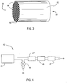
- Figure 4 shows an exemplary embodiment of the emissions treatment system 40 including a diesel engine 41 emitting an exhaust stream including particulate matter, NO x and carbon monoxide.
- a catalyzed soot filter 45 is positioned downstream of and in flow communication with the diesel engine 41.
- the catalyzed soot filter 45 has a first ammonia SCR catalyst coating permeating the porous walls of the substrate and a second ammonia SCR catalyst coating on the inlet surface of the porous walls.
- the first substrate 45 is a wall-flow substrate.
- the first ammonia SCR catalyst and the second ammonia SCR catalyst are substantially free of platinum group metals.
- Various embodiments of the engine treatment system can include other optional catalyst components 47.
- the optional components 47 can be placed before and/or after the catalyzed soot filter 45.
- suitable optional components 47 include oxidation catalysts, reduction catalysts, NO x storage/trapping components.
- Some embodiments of the treatment system may also include a reductant or air injector 48 and a metering device 49.
- the reductant or air injection 48 is shown upstream of the catalyzed soot filter 45, but can be located downstream of the filter 45.
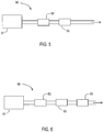
- Figure 5 shows a specific embodiment of an emissions treatment system 50. Downstream of, and in flow communication with the engine 51 is a diesel oxidation catalyst (DOC) 52.
- DOC diesel oxidation catalyst
- Downstream of and in flow communication with the DOC is a catalyzed soot filter 55 as described herein.
- Figure 6 shows another specific embodiment of an emissions treatment system 60. Downstream of, and in flow communication with an engine 61 is a diesel oxidation catalyst 62. Downstream of, and in flow communication with the DOC 62, is a lean NO x trap (LNT) 63. Downstream of, and in flow communication with the LNT 63, is a catalyzed soot filter 65 as described herein.
- LNT lean NO x trap
Claims (11)
- Article catalytique comprenant :un filtre à écoulement par les parois ayant une extrémité d'entrée, une extrémité de sortie, des canaux d'entrée et des canaux de sortie en alternance, et des parois poreuses séparant les canaux d'entrée des canaux de sortie, les canaux d'entrée ayant des bouchons à l'extrémité de sortie et les canaux de sortie ayant des bouchons à l'extrémité d'entrée, les parois poreuses ayant un diamètre moyen de pores et une distribution de taille de pores ;un premier matériau catalyseur RCS à l'ammoniac incorporé dans les parois poreuses à une première charge, le premier matériau catalyseur RCS ayant une première taille moyenne de particules et une première distribution de taille de particules ; etun deuxième matériau catalyseur RCS à l'ammoniac sur la surface des parois poreuses à une deuxième charge, le deuxième matériau catalyseur RCS ayant une deuxième taille moyenne de particules et une deuxième distribution de taille de particules, le premier tout comme le deuxième matériau catalyseur RCS ne contenant aucun composant métallique du groupe du platine ajouté, la deuxième taille moyenne de particules étant supérieure à la première taille moyenne de particules ;dans lequel le rapport entre le diamètre moyen de pores et la taille de particules D90 de la première composition RCS à l'ammoniac se situe dans la gamme de plus de 12,5 à 50, et dans lequel le deuxième matériau catalyseur RCS à l'ammoniac est déposé uniquement sur les parois des canaux d'entrée du filtre à écoulement par les parois.
- Article catalytique de la revendication 1, dans lequel le premier matériau catalyseur et le deuxième matériau catalyseur sont différents.
- Article catalytique de l'une quelconque des revendications 1 et 2, dans lequel la première charge et la deuxième charge sont différentes.
- Article catalytique de l'une quelconque des revendications 1 à 3, dans lequel la porosité à la surface de la paroi poreuse catalysée au voisinage des canaux d'entrée est inférieure à la porosité à l'intérieur de la paroi.
- Article catalytique de l'une quelconque des revendications 1 à 4, dans lequel le rapport entre le diamètre moyen de pores et une taille de particules D90 de la première composition RCS à l'ammoniac se situe dans la gamme de plus de 12,5 à 15.
- Article catalytique de l'une quelconque des revendications 1 à 5, dans lequel le rapport entre le diamètre moyen de pores et une taille de particules D90 de la deuxième composition RCS à l'ammoniac se situe dans la gamme de 0,05 à 5.
- Article catalytique de la revendication 6, dans lequel le rapport entre le diamètre moyen de pores et une taille de particules D90 de la deuxième composition RCS à l'ammoniac se situe dans la gamme de 0,2 à 0,75.
- Procédé de fabrication d'un filtre à suie catalysé comprenant les étapes suivantes :préparer une première suspension de catalyseur RCS à l'ammoniac ayant un premier catalyseur RCS à l'ammoniac, une première charge en matières solides de la suspension, une première taille moyenne de particules, une première distribution de taille de particules et une première viscosité, la première suspension de catalyseur RCS à l'ammoniac ne contenant aucun composant métallique du groupe du platine ajouté ;recouvrir un substrat de filtre à écoulement par les parois avec la première suspension de catalyseur RCS à l'ammoniac, le substrat ayant une extrémité d'entrée, une extrémité de sortie, des canaux d'entrée, des canaux de sortie et des parois poreuses séparant les canaux d'entrée des canaux de sortie, les canaux d'entrée ayant des bouchons à l'extrémité de sortie et les canaux de sortie ayant des bouchons à l'extrémité d'entrée, la première suspension de catalyseur RCS à l'ammoniac perméant à travers les parois poreuses du substrat, les parois poreuses ayant une taille moyenne de pores ;préparer une deuxième suspension de catalyseur RCS à l'ammoniac ayant un deuxième catalyseur RCS à l'ammoniac, une deuxième charge en matières solides de la suspension, une deuxième taille moyenne de particules, une deuxième distribution de taille de particules et une deuxième viscosité, la deuxième suspension de catalyseur RCS à l'ammoniac ne contenant aucun composant métallique du groupe du platine ajouté ;recouvrir le substrat avec la deuxième suspension de catalyseur RCS à l'ammoniac de telle sorte que le deuxième catalyseur RCS à l'ammoniac soit appliqué uniquement à la surface des parois poreuses du substrat au voisinage des canaux d'entrée ;dans lequel la deuxième taille moyenne de particules est supérieure à la première taille moyenne de particules ;et dans lequel le rapport entre le diamètre moyen de pores et la taille de particules D90 de la première composition RCS à l'ammoniac se situe dans la gamme de plus de 12,5 à 50.
- Procédé de la revendication 8, dans lequel la deuxième viscosité est supérieure à la première viscosité.
- Procédé de traitement d'un courant de gaz d'échappement d'un moteur diesel comprenant le passage du gaz d'échappement à travers l'article catalytique de l'une quelconque des revendications 1 à 7.
- Système de traitement de gaz d'échappement comprenant un moteur diesel et l'article catalytique de l'une quelconque des revendications 1 à 7 positionné en aval de et en communication fluidique avec le moteur.
Applications Claiming Priority (3)
| Application Number | Priority Date | Filing Date | Title |
|---|---|---|---|
| US33144510P | 2010-05-05 | 2010-05-05 | |
| US13/100,663 US8663587B2 (en) | 2010-05-05 | 2011-05-04 | Catalyzed soot filter and emissions treatment systems and methods |
| PCT/US2011/035230 WO2011140248A2 (fr) | 2010-05-05 | 2011-05-04 | Filtre anti-suie catalysé, systèmes et procédés de traitement des émissions |
Publications (3)
| Publication Number | Publication Date |
|---|---|
| EP2567078A2 EP2567078A2 (fr) | 2013-03-13 |
| EP2567078A4 EP2567078A4 (fr) | 2014-09-17 |
| EP2567078B1 true EP2567078B1 (fr) | 2017-09-27 |
Family
ID=44902059
Family Applications (1)
| Application Number | Title | Priority Date | Filing Date |
|---|---|---|---|
| EP11778282.1A Active EP2567078B1 (fr) | 2010-05-05 | 2011-05-04 | Filtre anti-suie catalysé, systèmes et procédés de traitement des émissions |
Country Status (11)
| Country | Link |
|---|---|
| US (1) | US8663587B2 (fr) |
| EP (1) | EP2567078B1 (fr) |
| JP (1) | JP5628413B2 (fr) |
| KR (1) | KR101476901B1 (fr) |
| CN (1) | CN102959191B (fr) |
| BR (1) | BR112012028302A2 (fr) |
| CA (1) | CA2798326C (fr) |
| MX (1) | MX350977B (fr) |
| MY (1) | MY163935A (fr) |
| WO (1) | WO2011140248A2 (fr) |
| ZA (1) | ZA201209016B (fr) |
Families Citing this family (33)
| Publication number | Priority date | Publication date | Assignee | Title |
|---|---|---|---|---|
| US8512657B2 (en) | 2009-02-26 | 2013-08-20 | Johnson Matthey Public Limited Company | Method and system using a filter for treating exhaust gas having particulate matter |
| JP5904646B2 (ja) * | 2010-08-31 | 2016-04-13 | コーニング インコーポレイテッド | コーティングされたチャネルを有するセルラーセラミック物品及びその製法 |
| US9029813B2 (en) * | 2011-05-20 | 2015-05-12 | Asml Netherlands B.V. | Filter for material supply apparatus of an extreme ultraviolet light source |
| WO2013145317A1 (fr) * | 2012-03-30 | 2013-10-03 | イビデン株式会社 | Filtre en nid d'abeilles et procédé de production d'un filtre en nid d'abeilles |
| GB2502953B (en) * | 2012-05-24 | 2017-02-08 | Imp Innovations Ltd | Catalytic converter substrate |
| EP2988851B1 (fr) * | 2013-04-24 | 2020-08-12 | Johnson Matthey Public Limited Company | Moteur à allumage commandé avec substrat filtrant comprenant une couche catalytique revêtant des zones |
| DE102014107667A1 (de) * | 2013-05-31 | 2014-12-04 | Johnson Matthey Public Ltd., Co. | Katalysiertes filter zum behandeln von abgas |
| RU2629762C2 (ru) * | 2013-05-31 | 2017-09-01 | Джонсон Мэтти Паблик Лимитед Компани | Каталитический фильтр для обработки отработавшего газа |
| US9579638B2 (en) * | 2013-07-30 | 2017-02-28 | Johnson Matthey Public Limited Company | Ammonia slip catalyst |
| GB2517951A (en) * | 2013-09-05 | 2015-03-11 | Imp Innovations Ltd | A substrate and a method of manufacturing a substrate |
| EP3140038A1 (fr) * | 2014-05-09 | 2017-03-15 | Johnson Matthey Public Limited Company | Catalyseur de conversion d'ammoniac dans lequel du platine est imprégné sur des substrats de porosité élevée |
| DE102014215112A1 (de) * | 2014-07-31 | 2016-02-04 | Johnson Matthey Public Limited Company | Verfahren zur Herstellung eines Katalysators sowie Katalysator-Artikel |
| DE102014112862A1 (de) * | 2014-09-08 | 2016-03-10 | Continental Automotive Gmbh | Partikelfilter und Verfahren zur Herstellung eines Partikelfilters |
| WO2016060050A1 (fr) * | 2014-10-16 | 2016-04-21 | 株式会社キャタラー | Catalyseur pour purification des gaz d'échappement |
| RU2702578C2 (ru) * | 2014-11-19 | 2019-10-08 | Джонсон Мэтти Паблик Лимитед Компани | Объединение scr с pna для низкотемпературного контроля выхлопных газов |
| BR112017020825A2 (pt) * | 2015-03-30 | 2018-07-03 | Basf Corp | filtro particulado catalisado, e, método para fabricar um filtro particulado revestido |
| KR102302675B1 (ko) * | 2015-04-21 | 2021-09-16 | 할도르 토프쉐 에이/에스 | 유황 가스 스트림으로부터 그을음의 제거 방법 |
| GB2542654B (en) | 2015-06-28 | 2019-12-04 | Johnson Matthey Plc | Catalytic wall-flow filter having a membrane |
| CN105257375A (zh) * | 2015-10-08 | 2016-01-20 | 南京依柯卡特汽车催化器有限公司 | 一种基于多层壁流式的催化器 |
| KR20180127514A (ko) * | 2016-04-13 | 2018-11-28 | 우미코레 아게 운트 코 카게 | Scr-활성 코팅을 갖는 촉매 |
| CN108697980A (zh) | 2016-04-13 | 2018-10-23 | 优美科股份公司及两合公司 | 具有scr活性涂层的颗粒过滤器 |
| EP3281699A1 (fr) | 2016-08-11 | 2018-02-14 | Umicore AG & Co. KG | Filtre à particules avec catalyseur de réduction catalytique sélective |
| US10138777B2 (en) * | 2016-08-25 | 2018-11-27 | GM Global Technology Operations LLC | Apparatus and methods for evaluating a soot quantity accumulated in a selective catalytic reduction washcoated particulate filter |
| EP3296009B1 (fr) | 2016-09-20 | 2019-03-27 | Umicore AG & Co. KG | Filtre à particules avec revêtement active à réduction catalytique sélective |
| DE102017103341A1 (de) * | 2017-02-17 | 2018-08-23 | Umicore Ag & Co. Kg | Russpartikelfilter mit speicherzellen für katalysator |
| JP6605522B2 (ja) | 2017-03-09 | 2019-11-13 | 株式会社キャタラー | 排ガス浄化用触媒 |
| GB2562161A (en) * | 2017-03-20 | 2018-11-07 | Johnson Matthey Plc | Rear on-wall design SCRF |
| DE102018121503A1 (de) | 2017-09-05 | 2019-03-07 | Umicore Ag & Co. Kg | Abgasreinigung mit NO-Oxidationskatalysator und SCR-aktivem Partikelfilter |
| CN111315970B (zh) * | 2017-11-10 | 2023-02-03 | 巴斯夫公司 | 氨氧化减少的催化烟灰过滤器 |
| BR112020015582A2 (pt) * | 2018-02-05 | 2021-02-02 | Basf Corporation | catalisador de conversão de quatro vias, processo para preparar o catalisador, sistema de tratamento de gás de escape e uso de um catalisador |
| JP7391045B2 (ja) * | 2018-02-05 | 2023-12-04 | ビーエーエスエフ コーポレーション | 改善されたフィルタ特性を有する四元変換触媒 |
| DE102019100107A1 (de) | 2019-01-04 | 2020-07-09 | Umicore Ag & Co. Kg | Katalytisch aktives Filtersubstrat und Verfahren zur Herstellung sowie deren Verwendung |
| DE102019209303A1 (de) * | 2019-06-26 | 2020-12-31 | Vitesco Technologies GmbH | Vorrichtung zur Abgasnachbehandlung |
Citations (8)
| Publication number | Priority date | Publication date | Assignee | Title |
|---|---|---|---|---|
| EP0766993A2 (fr) | 1995-10-02 | 1997-04-09 | Toyota Jidosha Kabushiki Kaisha | Filtre pour purifier le gaz d'échappement |
| JPH09173866A (ja) | 1995-12-28 | 1997-07-08 | Nippon Soken Inc | ディーゼル排ガス浄化フィルタ |
| DE102004040551A1 (de) * | 2004-08-21 | 2006-02-23 | Umicore Ag & Co. Kg | Verfahren zur Beschichtung eines Wandflußfilters mit einer Beschichtungszusammensetzung |
| EP1837494A2 (fr) | 2006-03-24 | 2007-09-26 | Ngk Insulators, Ltd. | Système de purification de gaz d'échappement |
| US20080044319A1 (en) | 2005-08-31 | 2008-02-21 | Ngk Insulators, Ltd. | Honeycomb catalyst and manufacturing method thereof |
| WO2008101585A1 (fr) | 2007-02-23 | 2008-08-28 | Umicore Ag & Co. Kg | Filtre à particules diesel à activation catalytique présentant un effet de blocage d'ammoniac |
| KR100882665B1 (ko) | 2007-11-20 | 2009-02-06 | 현대자동차주식회사 | 매연 여과장치 |
| US20100077738A1 (en) | 2008-09-30 | 2010-04-01 | Ford Global Technologies, Llc | System for Reducing NOx in Exhaust |
Family Cites Families (25)
| Publication number | Priority date | Publication date | Assignee | Title |
|---|---|---|---|---|
| US295482A (en) | 1884-03-18 | Combined car coupler and buffer | ||
| US44319A (en) | 1864-09-20 | Improvement in converting rotary into reciprocating motion | ||
| US3111396A (en) | 1960-12-14 | 1963-11-19 | Gen Electric | Method of making a porous material |
| JPS5523086B2 (fr) | 1973-03-26 | 1980-06-20 | ||
| US4085193A (en) | 1973-12-12 | 1978-04-18 | Mitsubishi Petrochemical Co. Ltd. | Catalytic process for reducing nitrogen oxides to nitrogen |
| US5221484A (en) | 1991-01-10 | 1993-06-22 | Ceramem Separations Limited Partnership | Catalytic filtration device and method |
| DE19782282T1 (de) * | 1997-07-10 | 2000-09-21 | Sk Corp | Selektive katalytische Reduktion zur Entfernung von Stickoxiden und zugehöriger Katalysatorkörper |
| US6162415A (en) | 1997-10-14 | 2000-12-19 | Exxon Chemical Patents Inc. | Synthesis of SAPO-44 |
| US7264789B1 (en) | 1998-07-29 | 2007-09-04 | Exxonmobil Chemical Patents Inc. | Crystalline molecular sieves |
| JP3874270B2 (ja) * | 2002-09-13 | 2007-01-31 | トヨタ自動車株式会社 | 排ガス浄化フィルタ触媒及びその製造方法 |
| US7119044B2 (en) | 2003-06-11 | 2006-10-10 | Delphi Technologies, Inc. | Multiple washcoats on filter substrate |
| US7481983B2 (en) * | 2004-08-23 | 2009-01-27 | Basf Catalysts Llc | Zone coated catalyst to simultaneously reduce NOx and unreacted ammonia |
| FR2893861B1 (fr) * | 2005-11-30 | 2008-01-04 | Saint Gobain Ct Recherches | Structure de filtration d'un gaz a base de sic de porosite de surface de paroi controlee |
| JP2009519814A (ja) * | 2005-12-16 | 2009-05-21 | コーニング インコーポレイテッド | 圧力降下の低い被覆ディーゼル排ガスフィルタ |
| DE102005061873A1 (de) * | 2005-12-23 | 2007-07-05 | Robert Bosch Gmbh | Verfahren und Steuergerät zum Betreiben eines integrierten SCR/DPF-Systems |
| US7943097B2 (en) * | 2007-01-09 | 2011-05-17 | Catalytic Solutions, Inc. | Reactor system for reducing NOx emissions from boilers |
| US7767175B2 (en) * | 2007-01-09 | 2010-08-03 | Catalytic Solutions, Inc. | Ammonia SCR catalyst and method of using the catalyst |
| CA2679590C (fr) | 2007-02-27 | 2016-06-07 | Basf Catalysts Llc | Catalyseurs de zeolite cha cuivre |
| US7886529B2 (en) * | 2007-05-30 | 2011-02-15 | Gm Global Technology Operations, Inc. | Electrically heated DPF/SCR 2-way system |
| US7802420B2 (en) | 2007-07-26 | 2010-09-28 | Eaton Corporation | Catalyst composition and structure for a diesel-fueled autothermal reformer placed in and exhaust stream |
| US8038954B2 (en) * | 2008-02-14 | 2011-10-18 | Basf Corporation | CSF with low platinum/palladium ratios |
| ATE476246T1 (de) * | 2008-05-23 | 2010-08-15 | Umicore Ag & Co Kg | Vorrichtung zur reinigung von dieselabgasen |
| JP4656188B2 (ja) * | 2008-05-30 | 2011-03-23 | マツダ株式会社 | 排気ガス浄化用触媒 |
| US8245500B2 (en) | 2008-07-07 | 2012-08-21 | Delphi Technologies, Inc. | Dual catalyst NOx reduction system for exhaust from lean burn internal combustion engines |
| US20100101221A1 (en) * | 2008-10-28 | 2010-04-29 | Caterpillar Inc. | CATALYSTS, SYSTEMS, AND METHODS FOR REDUCING NOx IN AN EXHAUST GAS |
-
2011
- 2011-05-04 CN CN201180032385.4A patent/CN102959191B/zh active Active
- 2011-05-04 EP EP11778282.1A patent/EP2567078B1/fr active Active
- 2011-05-04 KR KR1020127031718A patent/KR101476901B1/ko active IP Right Grant
- 2011-05-04 JP JP2013509229A patent/JP5628413B2/ja active Active
- 2011-05-04 US US13/100,663 patent/US8663587B2/en active Active
- 2011-05-04 WO PCT/US2011/035230 patent/WO2011140248A2/fr active Application Filing
- 2011-05-04 MX MX2012012828A patent/MX350977B/es active IP Right Grant
- 2011-05-04 CA CA2798326A patent/CA2798326C/fr not_active Expired - Fee Related
- 2011-05-04 MY MYPI2012004809A patent/MY163935A/en unknown
- 2011-05-04 BR BR112012028302A patent/BR112012028302A2/pt not_active Application Discontinuation
-
2012
- 2012-11-29 ZA ZA2012/09016A patent/ZA201209016B/en unknown
Patent Citations (9)
| Publication number | Priority date | Publication date | Assignee | Title |
|---|---|---|---|---|
| EP0766993A2 (fr) | 1995-10-02 | 1997-04-09 | Toyota Jidosha Kabushiki Kaisha | Filtre pour purifier le gaz d'échappement |
| JPH09173866A (ja) | 1995-12-28 | 1997-07-08 | Nippon Soken Inc | ディーゼル排ガス浄化フィルタ |
| DE102004040551A1 (de) * | 2004-08-21 | 2006-02-23 | Umicore Ag & Co. Kg | Verfahren zur Beschichtung eines Wandflußfilters mit einer Beschichtungszusammensetzung |
| US20080107806A1 (en) | 2004-08-21 | 2008-05-08 | Umicore Ag & Co.Kg | Method for Coating a Wall Flow Filter With a Coating Composition |
| US20080044319A1 (en) | 2005-08-31 | 2008-02-21 | Ngk Insulators, Ltd. | Honeycomb catalyst and manufacturing method thereof |
| EP1837494A2 (fr) | 2006-03-24 | 2007-09-26 | Ngk Insulators, Ltd. | Système de purification de gaz d'échappement |
| WO2008101585A1 (fr) | 2007-02-23 | 2008-08-28 | Umicore Ag & Co. Kg | Filtre à particules diesel à activation catalytique présentant un effet de blocage d'ammoniac |
| KR100882665B1 (ko) | 2007-11-20 | 2009-02-06 | 현대자동차주식회사 | 매연 여과장치 |
| US20100077738A1 (en) | 2008-09-30 | 2010-04-01 | Ford Global Technologies, Llc | System for Reducing NOx in Exhaust |
Also Published As
| Publication number | Publication date |
|---|---|
| CN102959191B (zh) | 2015-05-13 |
| KR101476901B1 (ko) | 2014-12-26 |
| US8663587B2 (en) | 2014-03-04 |
| WO2011140248A2 (fr) | 2011-11-10 |
| MX2012012828A (es) | 2013-01-28 |
| CA2798326A1 (fr) | 2011-11-10 |
| US20110274601A1 (en) | 2011-11-10 |
| BR112012028302A2 (pt) | 2016-11-01 |
| EP2567078A4 (fr) | 2014-09-17 |
| JP2013532049A (ja) | 2013-08-15 |
| CA2798326C (fr) | 2014-11-04 |
| KR20130064075A (ko) | 2013-06-17 |
| JP5628413B2 (ja) | 2014-11-19 |
| WO2011140248A3 (fr) | 2012-03-15 |
| ZA201209016B (en) | 2014-03-26 |
| EP2567078A2 (fr) | 2013-03-13 |
| CN102959191A (zh) | 2013-03-06 |
| MX350977B (es) | 2017-09-27 |
| MY163935A (en) | 2017-11-15 |
Similar Documents
| Publication | Publication Date | Title |
|---|---|---|
| EP2567078B1 (fr) | Filtre anti-suie catalysé, systèmes et procédés de traitement des émissions | |
| US8544260B2 (en) | Emissions treatment systems and methods with catalyzed SCR filter and downstream SCR catalyst | |
| EP2382031B1 (fr) | Systèmes et procédés de traitement d'émissions employant un filtre rcs catalysé et un catalyseur rcs aval | |
| EP2691165B1 (fr) | Filtre multicomposant pour maîtrise des émissions | |
| US20180045097A1 (en) | Filter Catalyzed With SCR Catalyst, Systems And Methods | |
| KR102345897B1 (ko) | 비금속 촉매 | |
| JP6138911B2 (ja) | CO/HCライトオフ及びHCストレージ機能を備えたPt−Pdディーゼル酸化触媒 | |
| US8038954B2 (en) | CSF with low platinum/palladium ratios | |
| US20140301923A1 (en) | Selective Catalytic Reduction Catalyst System | |
| KR20150128697A (ko) | 선택적 촉매 환원 촉매 시스템 | |
| CN117489449A (zh) | 排气处理系统 | |
| US10137413B2 (en) | Diesel oxidation catalyst having a capture region for sulfur containing impurities | |
| US20210114007A1 (en) | Mixed zeolite-containing scr catalyst | |
| KR20230116024A (ko) | 집중-분포된 기능성 물질 층을 갖는 미립자 필터 및그 제조방법 |
Legal Events
| Date | Code | Title | Description |
|---|---|---|---|
| PUAI | Public reference made under article 153(3) epc to a published international application that has entered the european phase |
Free format text: ORIGINAL CODE: 0009012 |
|
| 17P | Request for examination filed |
Effective date: 20121205 |
|
| AK | Designated contracting states |
Kind code of ref document: A2 Designated state(s): AL AT BE BG CH CY CZ DE DK EE ES FI FR GB GR HR HU IE IS IT LI LT LU LV MC MK MT NL NO PL PT RO RS SE SI SK SM TR |
|
| DAX | Request for extension of the european patent (deleted) | ||
| A4 | Supplementary search report drawn up and despatched |
Effective date: 20140819 |
|
| RIC1 | Information provided on ipc code assigned before grant |
Ipc: F01N 3/20 20060101ALI20140812BHEP Ipc: F01N 3/28 20060101ALI20140812BHEP Ipc: F01N 3/035 20060101ALI20140812BHEP Ipc: F01N 3/021 20060101ALI20140812BHEP Ipc: B01D 53/94 20060101AFI20140812BHEP |
|
| 17Q | First examination report despatched |
Effective date: 20150713 |
|
| REG | Reference to a national code |
Ref country code: DE Ref legal event code: R079 Ref document number: 602011041950 Country of ref document: DE Free format text: PREVIOUS MAIN CLASS: F01N0003035000 Ipc: B01D0053940000 |
|
| GRAP | Despatch of communication of intention to grant a patent |
Free format text: ORIGINAL CODE: EPIDOSNIGR1 |
|
| STAA | Information on the status of an ep patent application or granted ep patent |
Free format text: STATUS: GRANT OF PATENT IS INTENDED |
|
| RIC1 | Information provided on ipc code assigned before grant |
Ipc: F01N 3/035 20060101ALI20170328BHEP Ipc: F01N 3/021 20060101ALI20170328BHEP Ipc: F01N 3/28 20060101ALI20170328BHEP Ipc: F01N 3/20 20060101ALI20170328BHEP Ipc: B01D 53/94 20060101AFI20170328BHEP Ipc: F01N 13/00 20100101ALI20170328BHEP |
|
| INTG | Intention to grant announced |
Effective date: 20170412 |
|
| GRAS | Grant fee paid |
Free format text: ORIGINAL CODE: EPIDOSNIGR3 |
|
| GRAA | (expected) grant |
Free format text: ORIGINAL CODE: 0009210 |
|
| STAA | Information on the status of an ep patent application or granted ep patent |
Free format text: STATUS: THE PATENT HAS BEEN GRANTED |
|
| RAP1 | Party data changed (applicant data changed or rights of an application transferred) |
Owner name: BASF CORPORATION |
|
| AK | Designated contracting states |
Kind code of ref document: B1 Designated state(s): AL AT BE BG CH CY CZ DE DK EE ES FI FR GB GR HR HU IE IS IT LI LT LU LV MC MK MT NL NO PL PT RO RS SE SI SK SM TR |
|
| REG | Reference to a national code |
Ref country code: GB Ref legal event code: FG4D |
|
| REG | Reference to a national code |
Ref country code: CH Ref legal event code: EP |
|
| REG | Reference to a national code |
Ref country code: AT Ref legal event code: REF Ref document number: 931475 Country of ref document: AT Kind code of ref document: T Effective date: 20171015 |
|
| REG | Reference to a national code |
Ref country code: IE Ref legal event code: FG4D |
|
| REG | Reference to a national code |
Ref country code: DE Ref legal event code: R096 Ref document number: 602011041950 Country of ref document: DE |
|
| PG25 | Lapsed in a contracting state [announced via postgrant information from national office to epo] |
Ref country code: NO Free format text: LAPSE BECAUSE OF FAILURE TO SUBMIT A TRANSLATION OF THE DESCRIPTION OR TO PAY THE FEE WITHIN THE PRESCRIBED TIME-LIMIT Effective date: 20171227 Ref country code: FI Free format text: LAPSE BECAUSE OF FAILURE TO SUBMIT A TRANSLATION OF THE DESCRIPTION OR TO PAY THE FEE WITHIN THE PRESCRIBED TIME-LIMIT Effective date: 20170927 Ref country code: SE Free format text: LAPSE BECAUSE OF FAILURE TO SUBMIT A TRANSLATION OF THE DESCRIPTION OR TO PAY THE FEE WITHIN THE PRESCRIBED TIME-LIMIT Effective date: 20170927 Ref country code: LT Free format text: LAPSE BECAUSE OF FAILURE TO SUBMIT A TRANSLATION OF THE DESCRIPTION OR TO PAY THE FEE WITHIN THE PRESCRIBED TIME-LIMIT Effective date: 20170927 Ref country code: HR Free format text: LAPSE BECAUSE OF FAILURE TO SUBMIT A TRANSLATION OF THE DESCRIPTION OR TO PAY THE FEE WITHIN THE PRESCRIBED TIME-LIMIT Effective date: 20170927 |
|
| REG | Reference to a national code |
Ref country code: NL Ref legal event code: MP Effective date: 20170927 |
|
| REG | Reference to a national code |
Ref country code: LT Ref legal event code: MG4D |
|
| REG | Reference to a national code |
Ref country code: AT Ref legal event code: MK05 Ref document number: 931475 Country of ref document: AT Kind code of ref document: T Effective date: 20170927 |
|
| PG25 | Lapsed in a contracting state [announced via postgrant information from national office to epo] |
Ref country code: GR Free format text: LAPSE BECAUSE OF FAILURE TO SUBMIT A TRANSLATION OF THE DESCRIPTION OR TO PAY THE FEE WITHIN THE PRESCRIBED TIME-LIMIT Effective date: 20171228 Ref country code: BG Free format text: LAPSE BECAUSE OF FAILURE TO SUBMIT A TRANSLATION OF THE DESCRIPTION OR TO PAY THE FEE WITHIN THE PRESCRIBED TIME-LIMIT Effective date: 20171227 Ref country code: RS Free format text: LAPSE BECAUSE OF FAILURE TO SUBMIT A TRANSLATION OF THE DESCRIPTION OR TO PAY THE FEE WITHIN THE PRESCRIBED TIME-LIMIT Effective date: 20170927 Ref country code: LV Free format text: LAPSE BECAUSE OF FAILURE TO SUBMIT A TRANSLATION OF THE DESCRIPTION OR TO PAY THE FEE WITHIN THE PRESCRIBED TIME-LIMIT Effective date: 20170927 |
|
| PG25 | Lapsed in a contracting state [announced via postgrant information from national office to epo] |
Ref country code: NL Free format text: LAPSE BECAUSE OF FAILURE TO SUBMIT A TRANSLATION OF THE DESCRIPTION OR TO PAY THE FEE WITHIN THE PRESCRIBED TIME-LIMIT Effective date: 20170927 |
|
| PG25 | Lapsed in a contracting state [announced via postgrant information from national office to epo] |
Ref country code: CZ Free format text: LAPSE BECAUSE OF FAILURE TO SUBMIT A TRANSLATION OF THE DESCRIPTION OR TO PAY THE FEE WITHIN THE PRESCRIBED TIME-LIMIT Effective date: 20170927 Ref country code: RO Free format text: LAPSE BECAUSE OF FAILURE TO SUBMIT A TRANSLATION OF THE DESCRIPTION OR TO PAY THE FEE WITHIN THE PRESCRIBED TIME-LIMIT Effective date: 20170927 Ref country code: ES Free format text: LAPSE BECAUSE OF FAILURE TO SUBMIT A TRANSLATION OF THE DESCRIPTION OR TO PAY THE FEE WITHIN THE PRESCRIBED TIME-LIMIT Effective date: 20170927 |
|
| REG | Reference to a national code |
Ref country code: FR Ref legal event code: PLFP Year of fee payment: 8 |
|
| PG25 | Lapsed in a contracting state [announced via postgrant information from national office to epo] |
Ref country code: SK Free format text: LAPSE BECAUSE OF FAILURE TO SUBMIT A TRANSLATION OF THE DESCRIPTION OR TO PAY THE FEE WITHIN THE PRESCRIBED TIME-LIMIT Effective date: 20170927 Ref country code: IS Free format text: LAPSE BECAUSE OF FAILURE TO SUBMIT A TRANSLATION OF THE DESCRIPTION OR TO PAY THE FEE WITHIN THE PRESCRIBED TIME-LIMIT Effective date: 20180127 Ref country code: SM Free format text: LAPSE BECAUSE OF FAILURE TO SUBMIT A TRANSLATION OF THE DESCRIPTION OR TO PAY THE FEE WITHIN THE PRESCRIBED TIME-LIMIT Effective date: 20170927 Ref country code: IT Free format text: LAPSE BECAUSE OF FAILURE TO SUBMIT A TRANSLATION OF THE DESCRIPTION OR TO PAY THE FEE WITHIN THE PRESCRIBED TIME-LIMIT Effective date: 20170927 Ref country code: AT Free format text: LAPSE BECAUSE OF FAILURE TO SUBMIT A TRANSLATION OF THE DESCRIPTION OR TO PAY THE FEE WITHIN THE PRESCRIBED TIME-LIMIT Effective date: 20170927 Ref country code: EE Free format text: LAPSE BECAUSE OF FAILURE TO SUBMIT A TRANSLATION OF THE DESCRIPTION OR TO PAY THE FEE WITHIN THE PRESCRIBED TIME-LIMIT Effective date: 20170927 |
|
| REG | Reference to a national code |
Ref country code: DE Ref legal event code: R026 Ref document number: 602011041950 Country of ref document: DE |
|
| PLBI | Opposition filed |
Free format text: ORIGINAL CODE: 0009260 |
|
| PLAX | Notice of opposition and request to file observation + time limit sent |
Free format text: ORIGINAL CODE: EPIDOSNOBS2 |
|
| PG25 | Lapsed in a contracting state [announced via postgrant information from national office to epo] |
Ref country code: DK Free format text: LAPSE BECAUSE OF FAILURE TO SUBMIT A TRANSLATION OF THE DESCRIPTION OR TO PAY THE FEE WITHIN THE PRESCRIBED TIME-LIMIT Effective date: 20170927 |
|
| 26 | Opposition filed |
Opponent name: UMICORE AG & CO. KG Effective date: 20180625 |
|
| PG25 | Lapsed in a contracting state [announced via postgrant information from national office to epo] |
Ref country code: PL Free format text: LAPSE BECAUSE OF FAILURE TO SUBMIT A TRANSLATION OF THE DESCRIPTION OR TO PAY THE FEE WITHIN THE PRESCRIBED TIME-LIMIT Effective date: 20170927 |
|
| REG | Reference to a national code |
Ref country code: SE Ref legal event code: RINS Effective date: 20181004 Ref country code: SE Ref legal event code: TRGR |
|
| PLBP | Opposition withdrawn |
Free format text: ORIGINAL CODE: 0009264 |
|
| PG25 | Lapsed in a contracting state [announced via postgrant information from national office to epo] |
Ref country code: IT Free format text: LAPSE BECAUSE OF FAILURE TO SUBMIT A TRANSLATION OF THE DESCRIPTION OR TO PAY THE FEE WITHIN THE PRESCRIBED TIME-LIMIT Effective date: 20170927 |
|
| PGRI | Patent reinstated in contracting state [announced from national office to epo] |
Ref country code: IT Effective date: 20180820 |
|
| PLBB | Reply of patent proprietor to notice(s) of opposition received |
Free format text: ORIGINAL CODE: EPIDOSNOBS3 |
|
| PG25 | Lapsed in a contracting state [announced via postgrant information from national office to epo] |
Ref country code: SI Free format text: LAPSE BECAUSE OF FAILURE TO SUBMIT A TRANSLATION OF THE DESCRIPTION OR TO PAY THE FEE WITHIN THE PRESCRIBED TIME-LIMIT Effective date: 20170927 |
|
| PG25 | Lapsed in a contracting state [announced via postgrant information from national office to epo] |
Ref country code: MC Free format text: LAPSE BECAUSE OF FAILURE TO SUBMIT A TRANSLATION OF THE DESCRIPTION OR TO PAY THE FEE WITHIN THE PRESCRIBED TIME-LIMIT Effective date: 20170927 |
|
| REG | Reference to a national code |
Ref country code: IE Ref legal event code: MM4A |
|
| PG25 | Lapsed in a contracting state [announced via postgrant information from national office to epo] |
Ref country code: LU Free format text: LAPSE BECAUSE OF NON-PAYMENT OF DUE FEES Effective date: 20180504 |
|
| PG25 | Lapsed in a contracting state [announced via postgrant information from national office to epo] |
Ref country code: IE Free format text: LAPSE BECAUSE OF NON-PAYMENT OF DUE FEES Effective date: 20180504 |
|
| PGFP | Annual fee paid to national office [announced via postgrant information from national office to epo] |
Ref country code: CZ Payment date: 20190430 Year of fee payment: 9 Ref country code: IT Payment date: 20190524 Year of fee payment: 9 |
|
| PGFP | Annual fee paid to national office [announced via postgrant information from national office to epo] |
Ref country code: SE Payment date: 20190527 Year of fee payment: 9 Ref country code: BE Payment date: 20190527 Year of fee payment: 9 |
|
| PGFP | Annual fee paid to national office [announced via postgrant information from national office to epo] |
Ref country code: CH Payment date: 20190527 Year of fee payment: 9 |
|
| PG25 | Lapsed in a contracting state [announced via postgrant information from national office to epo] |
Ref country code: SE Free format text: LAPSE BECAUSE OF FAILURE TO SUBMIT A TRANSLATION OF THE DESCRIPTION OR TO PAY THE FEE WITHIN THE PRESCRIBED TIME-LIMIT Effective date: 20170927 |
|
| PGRI | Patent reinstated in contracting state [announced from national office to epo] |
Ref country code: SE Effective date: 20181004 |
|
| PGFP | Annual fee paid to national office [announced via postgrant information from national office to epo] |
Ref country code: MK Payment date: 20190416 Year of fee payment: 9 |
|
| REG | Reference to a national code |
Ref country code: DE Ref legal event code: R100 Ref document number: 602011041950 Country of ref document: DE |
|
| PG25 | Lapsed in a contracting state [announced via postgrant information from national office to epo] |
Ref country code: MT Free format text: LAPSE BECAUSE OF NON-PAYMENT OF DUE FEES Effective date: 20180504 |
|
| PLCK | Communication despatched that opposition was rejected |
Free format text: ORIGINAL CODE: EPIDOSNREJ1 |
|
| PG25 | Lapsed in a contracting state [announced via postgrant information from national office to epo] |
Ref country code: TR Free format text: LAPSE BECAUSE OF FAILURE TO SUBMIT A TRANSLATION OF THE DESCRIPTION OR TO PAY THE FEE WITHIN THE PRESCRIBED TIME-LIMIT Effective date: 20170927 |
|
| PG25 | Lapsed in a contracting state [announced via postgrant information from national office to epo] |
Ref country code: PT Free format text: LAPSE BECAUSE OF FAILURE TO SUBMIT A TRANSLATION OF THE DESCRIPTION OR TO PAY THE FEE WITHIN THE PRESCRIBED TIME-LIMIT Effective date: 20170927 Ref country code: HU Free format text: LAPSE BECAUSE OF FAILURE TO SUBMIT A TRANSLATION OF THE DESCRIPTION OR TO PAY THE FEE WITHIN THE PRESCRIBED TIME-LIMIT; INVALID AB INITIO Effective date: 20110504 |
|
| PG25 | Lapsed in a contracting state [announced via postgrant information from national office to epo] |
Ref country code: CY Free format text: LAPSE BECAUSE OF FAILURE TO SUBMIT A TRANSLATION OF THE DESCRIPTION OR TO PAY THE FEE WITHIN THE PRESCRIBED TIME-LIMIT Effective date: 20170927 |
|
| PLBN | Opposition rejected |
Free format text: ORIGINAL CODE: 0009273 |
|
| STAA | Information on the status of an ep patent application or granted ep patent |
Free format text: STATUS: OPPOSITION REJECTED |
|
| PG25 | Lapsed in a contracting state [announced via postgrant information from national office to epo] |
Ref country code: AL Free format text: LAPSE BECAUSE OF FAILURE TO SUBMIT A TRANSLATION OF THE DESCRIPTION OR TO PAY THE FEE WITHIN THE PRESCRIBED TIME-LIMIT Effective date: 20170927 |
|
| 27O | Opposition rejected |
Effective date: 20191203 |
|
| PG25 | Lapsed in a contracting state [announced via postgrant information from national office to epo] |
Ref country code: LI Free format text: LAPSE BECAUSE OF NON-PAYMENT OF DUE FEES Effective date: 20200531 Ref country code: CZ Free format text: LAPSE BECAUSE OF NON-PAYMENT OF DUE FEES Effective date: 20200504 Ref country code: SE Free format text: LAPSE BECAUSE OF FAILURE TO SUBMIT A TRANSLATION OF THE DESCRIPTION OR TO PAY THE FEE WITHIN THE PRESCRIBED TIME-LIMIT Effective date: 20200505 Ref country code: CH Free format text: LAPSE BECAUSE OF NON-PAYMENT OF DUE FEES Effective date: 20200531 |
|
| REG | Reference to a national code |
Ref country code: BE Ref legal event code: MM Effective date: 20200531 |
|
| PG25 | Lapsed in a contracting state [announced via postgrant information from national office to epo] |
Ref country code: BE Free format text: LAPSE BECAUSE OF NON-PAYMENT OF DUE FEES Effective date: 20200531 |
|
| PGFP | Annual fee paid to national office [announced via postgrant information from national office to epo] |
Ref country code: FR Payment date: 20210526 Year of fee payment: 11 |
|
| PG25 | Lapsed in a contracting state [announced via postgrant information from national office to epo] |
Ref country code: IT Free format text: LAPSE BECAUSE OF FAILURE TO SUBMIT A TRANSLATION OF THE DESCRIPTION OR TO PAY THE FEE WITHIN THE PRESCRIBED TIME-LIMIT Effective date: 20200504 |
|
| PG25 | Lapsed in a contracting state [announced via postgrant information from national office to epo] |
Ref country code: FR Free format text: LAPSE BECAUSE OF NON-PAYMENT OF DUE FEES Effective date: 20220531 |
|
| P01 | Opt-out of the competence of the unified patent court (upc) registered |
Effective date: 20230314 |
|
| PGFP | Annual fee paid to national office [announced via postgrant information from national office to epo] |
Ref country code: DE Payment date: 20230530 Year of fee payment: 13 |
|
| PGFP | Annual fee paid to national office [announced via postgrant information from national office to epo] |
Ref country code: GB Payment date: 20230523 Year of fee payment: 13 |