EP2565555B1 - Refrigeration cycle apparatus - Google Patents
Refrigeration cycle apparatus Download PDFInfo
- Publication number
- EP2565555B1 EP2565555B1 EP10850639.5A EP10850639A EP2565555B1 EP 2565555 B1 EP2565555 B1 EP 2565555B1 EP 10850639 A EP10850639 A EP 10850639A EP 2565555 B1 EP2565555 B1 EP 2565555B1
- Authority
- EP
- European Patent Office
- Prior art keywords
- pressure
- refrigerant
- radiator
- refrigeration cycle
- cycle apparatus
- Prior art date
- Legal status (The legal status is an assumption and is not a legal conclusion. Google has not performed a legal analysis and makes no representation as to the accuracy of the status listed.)
- Active
Links
- 238000005057 refrigeration Methods 0.000 title claims description 73
- 239000003507 refrigerant Substances 0.000 claims description 230
- 238000002347 injection Methods 0.000 claims description 41
- 239000007924 injection Substances 0.000 claims description 41
- 238000001816 cooling Methods 0.000 claims description 38
- 230000009467 reduction Effects 0.000 claims description 9
- 230000000903 blocking effect Effects 0.000 claims description 2
- 230000003247 decreasing effect Effects 0.000 claims 1
- 238000007906 compression Methods 0.000 description 44
- 230000006835 compression Effects 0.000 description 41
- CURLTUGMZLYLDI-UHFFFAOYSA-N Carbon dioxide Chemical compound O=C=O CURLTUGMZLYLDI-UHFFFAOYSA-N 0.000 description 17
- 238000000034 method Methods 0.000 description 13
- 238000010586 diagram Methods 0.000 description 10
- 229910002092 carbon dioxide Inorganic materials 0.000 description 9
- 239000001569 carbon dioxide Substances 0.000 description 9
- 230000008569 process Effects 0.000 description 9
- 230000000694 effects Effects 0.000 description 8
- 230000001276 controlling effect Effects 0.000 description 5
- 230000007704 transition Effects 0.000 description 5
- XLYOFNOQVPJJNP-UHFFFAOYSA-N water Substances O XLYOFNOQVPJJNP-UHFFFAOYSA-N 0.000 description 5
- 238000010438 heat treatment Methods 0.000 description 4
- RTZKZFJDLAIYFH-UHFFFAOYSA-N Diethyl ether Chemical compound CCOCC RTZKZFJDLAIYFH-UHFFFAOYSA-N 0.000 description 3
- 238000010521 absorption reaction Methods 0.000 description 3
- 230000007423 decrease Effects 0.000 description 3
- 239000007788 liquid Substances 0.000 description 3
- 230000009471 action Effects 0.000 description 2
- 238000004378 air conditioning Methods 0.000 description 2
- 239000012267 brine Substances 0.000 description 2
- 230000008859 change Effects 0.000 description 2
- 230000001419 dependent effect Effects 0.000 description 2
- 238000001704 evaporation Methods 0.000 description 2
- 239000012071 phase Substances 0.000 description 2
- 230000001105 regulatory effect Effects 0.000 description 2
- HPALAKNZSZLMCH-UHFFFAOYSA-M sodium;chloride;hydrate Chemical compound O.[Na+].[Cl-] HPALAKNZSZLMCH-UHFFFAOYSA-M 0.000 description 2
- 238000011144 upstream manufacturing Methods 0.000 description 2
- CBENFWSGALASAD-UHFFFAOYSA-N Ozone Chemical compound [O-][O+]=O CBENFWSGALASAD-UHFFFAOYSA-N 0.000 description 1
- KYKAJFCTULSVSH-UHFFFAOYSA-N chloro(fluoro)methane Chemical compound F[C]Cl KYKAJFCTULSVSH-UHFFFAOYSA-N 0.000 description 1
- 230000000779 depleting effect Effects 0.000 description 1
- 238000009434 installation Methods 0.000 description 1
- 239000007791 liquid phase Substances 0.000 description 1
- 230000007246 mechanism Effects 0.000 description 1
- 239000000203 mixture Substances 0.000 description 1
- 230000002093 peripheral effect Effects 0.000 description 1
- 239000010726 refrigerant oil Substances 0.000 description 1
- 238000007789 sealing Methods 0.000 description 1
- 239000000243 solution Substances 0.000 description 1
- 239000012808 vapor phase Substances 0.000 description 1
- 238000010792 warming Methods 0.000 description 1
Images


Classifications
-
- F—MECHANICAL ENGINEERING; LIGHTING; HEATING; WEAPONS; BLASTING
- F25—REFRIGERATION OR COOLING; COMBINED HEATING AND REFRIGERATION SYSTEMS; HEAT PUMP SYSTEMS; MANUFACTURE OR STORAGE OF ICE; LIQUEFACTION SOLIDIFICATION OF GASES
- F25B—REFRIGERATION MACHINES, PLANTS OR SYSTEMS; COMBINED HEATING AND REFRIGERATION SYSTEMS; HEAT PUMP SYSTEMS
- F25B9/00—Compression machines, plants or systems, in which the refrigerant is air or other gas of low boiling point
- F25B9/002—Compression machines, plants or systems, in which the refrigerant is air or other gas of low boiling point characterised by the refrigerant
- F25B9/008—Compression machines, plants or systems, in which the refrigerant is air or other gas of low boiling point characterised by the refrigerant the refrigerant being carbon dioxide
-
- F—MECHANICAL ENGINEERING; LIGHTING; HEATING; WEAPONS; BLASTING
- F25—REFRIGERATION OR COOLING; COMBINED HEATING AND REFRIGERATION SYSTEMS; HEAT PUMP SYSTEMS; MANUFACTURE OR STORAGE OF ICE; LIQUEFACTION SOLIDIFICATION OF GASES
- F25B—REFRIGERATION MACHINES, PLANTS OR SYSTEMS; COMBINED HEATING AND REFRIGERATION SYSTEMS; HEAT PUMP SYSTEMS
- F25B1/00—Compression machines, plants or systems with non-reversible cycle
- F25B1/10—Compression machines, plants or systems with non-reversible cycle with multi-stage compression
-
- F—MECHANICAL ENGINEERING; LIGHTING; HEATING; WEAPONS; BLASTING
- F25—REFRIGERATION OR COOLING; COMBINED HEATING AND REFRIGERATION SYSTEMS; HEAT PUMP SYSTEMS; MANUFACTURE OR STORAGE OF ICE; LIQUEFACTION SOLIDIFICATION OF GASES
- F25B—REFRIGERATION MACHINES, PLANTS OR SYSTEMS; COMBINED HEATING AND REFRIGERATION SYSTEMS; HEAT PUMP SYSTEMS
- F25B2309/00—Gas cycle refrigeration machines
- F25B2309/06—Compression machines, plants or systems characterised by the refrigerant being carbon dioxide
- F25B2309/061—Compression machines, plants or systems characterised by the refrigerant being carbon dioxide with cycle highest pressure above the supercritical pressure
-
- F—MECHANICAL ENGINEERING; LIGHTING; HEATING; WEAPONS; BLASTING
- F25—REFRIGERATION OR COOLING; COMBINED HEATING AND REFRIGERATION SYSTEMS; HEAT PUMP SYSTEMS; MANUFACTURE OR STORAGE OF ICE; LIQUEFACTION SOLIDIFICATION OF GASES
- F25B—REFRIGERATION MACHINES, PLANTS OR SYSTEMS; COMBINED HEATING AND REFRIGERATION SYSTEMS; HEAT PUMP SYSTEMS
- F25B2400/00—General features or devices for refrigeration machines, plants or systems, combined heating and refrigeration systems or heat-pump systems, i.e. not limited to a particular subgroup of F25B
- F25B2400/04—Refrigeration circuit bypassing means
- F25B2400/0409—Refrigeration circuit bypassing means for the evaporator
-
- F—MECHANICAL ENGINEERING; LIGHTING; HEATING; WEAPONS; BLASTING
- F25—REFRIGERATION OR COOLING; COMBINED HEATING AND REFRIGERATION SYSTEMS; HEAT PUMP SYSTEMS; MANUFACTURE OR STORAGE OF ICE; LIQUEFACTION SOLIDIFICATION OF GASES
- F25B—REFRIGERATION MACHINES, PLANTS OR SYSTEMS; COMBINED HEATING AND REFRIGERATION SYSTEMS; HEAT PUMP SYSTEMS
- F25B2400/00—General features or devices for refrigeration machines, plants or systems, combined heating and refrigeration systems or heat-pump systems, i.e. not limited to a particular subgroup of F25B
- F25B2400/13—Economisers
-
- F—MECHANICAL ENGINEERING; LIGHTING; HEATING; WEAPONS; BLASTING
- F25—REFRIGERATION OR COOLING; COMBINED HEATING AND REFRIGERATION SYSTEMS; HEAT PUMP SYSTEMS; MANUFACTURE OR STORAGE OF ICE; LIQUEFACTION SOLIDIFICATION OF GASES
- F25B—REFRIGERATION MACHINES, PLANTS OR SYSTEMS; COMBINED HEATING AND REFRIGERATION SYSTEMS; HEAT PUMP SYSTEMS
- F25B2500/00—Problems to be solved
- F25B2500/07—Exceeding a certain pressure value in a refrigeration component or cycle
-
- F—MECHANICAL ENGINEERING; LIGHTING; HEATING; WEAPONS; BLASTING
- F25—REFRIGERATION OR COOLING; COMBINED HEATING AND REFRIGERATION SYSTEMS; HEAT PUMP SYSTEMS; MANUFACTURE OR STORAGE OF ICE; LIQUEFACTION SOLIDIFICATION OF GASES
- F25B—REFRIGERATION MACHINES, PLANTS OR SYSTEMS; COMBINED HEATING AND REFRIGERATION SYSTEMS; HEAT PUMP SYSTEMS
- F25B2500/00—Problems to be solved
- F25B2500/08—Exceeding a certain temperature value in a refrigeration component or cycle
-
- F—MECHANICAL ENGINEERING; LIGHTING; HEATING; WEAPONS; BLASTING
- F25—REFRIGERATION OR COOLING; COMBINED HEATING AND REFRIGERATION SYSTEMS; HEAT PUMP SYSTEMS; MANUFACTURE OR STORAGE OF ICE; LIQUEFACTION SOLIDIFICATION OF GASES
- F25B—REFRIGERATION MACHINES, PLANTS OR SYSTEMS; COMBINED HEATING AND REFRIGERATION SYSTEMS; HEAT PUMP SYSTEMS
- F25B2600/00—Control issues
- F25B2600/17—Control issues by controlling the pressure of the condenser
-
- F—MECHANICAL ENGINEERING; LIGHTING; HEATING; WEAPONS; BLASTING
- F25—REFRIGERATION OR COOLING; COMBINED HEATING AND REFRIGERATION SYSTEMS; HEAT PUMP SYSTEMS; MANUFACTURE OR STORAGE OF ICE; LIQUEFACTION SOLIDIFICATION OF GASES
- F25B—REFRIGERATION MACHINES, PLANTS OR SYSTEMS; COMBINED HEATING AND REFRIGERATION SYSTEMS; HEAT PUMP SYSTEMS
- F25B2600/00—Control issues
- F25B2600/25—Control of valves
- F25B2600/2509—Economiser valves
-
- F—MECHANICAL ENGINEERING; LIGHTING; HEATING; WEAPONS; BLASTING
- F25—REFRIGERATION OR COOLING; COMBINED HEATING AND REFRIGERATION SYSTEMS; HEAT PUMP SYSTEMS; MANUFACTURE OR STORAGE OF ICE; LIQUEFACTION SOLIDIFICATION OF GASES
- F25B—REFRIGERATION MACHINES, PLANTS OR SYSTEMS; COMBINED HEATING AND REFRIGERATION SYSTEMS; HEAT PUMP SYSTEMS
- F25B2700/00—Sensing or detecting of parameters; Sensors therefor
- F25B2700/19—Pressures
- F25B2700/193—Pressures of the compressor
- F25B2700/1931—Discharge pressures
-
- F—MECHANICAL ENGINEERING; LIGHTING; HEATING; WEAPONS; BLASTING
- F25—REFRIGERATION OR COOLING; COMBINED HEATING AND REFRIGERATION SYSTEMS; HEAT PUMP SYSTEMS; MANUFACTURE OR STORAGE OF ICE; LIQUEFACTION SOLIDIFICATION OF GASES
- F25B—REFRIGERATION MACHINES, PLANTS OR SYSTEMS; COMBINED HEATING AND REFRIGERATION SYSTEMS; HEAT PUMP SYSTEMS
- F25B2700/00—Sensing or detecting of parameters; Sensors therefor
- F25B2700/19—Pressures
- F25B2700/193—Pressures of the compressor
- F25B2700/1933—Suction pressures
-
- F—MECHANICAL ENGINEERING; LIGHTING; HEATING; WEAPONS; BLASTING
- F25—REFRIGERATION OR COOLING; COMBINED HEATING AND REFRIGERATION SYSTEMS; HEAT PUMP SYSTEMS; MANUFACTURE OR STORAGE OF ICE; LIQUEFACTION SOLIDIFICATION OF GASES
- F25B—REFRIGERATION MACHINES, PLANTS OR SYSTEMS; COMBINED HEATING AND REFRIGERATION SYSTEMS; HEAT PUMP SYSTEMS
- F25B2700/00—Sensing or detecting of parameters; Sensors therefor
- F25B2700/19—Pressures
- F25B2700/195—Pressures of the condenser
-
- F—MECHANICAL ENGINEERING; LIGHTING; HEATING; WEAPONS; BLASTING
- F25—REFRIGERATION OR COOLING; COMBINED HEATING AND REFRIGERATION SYSTEMS; HEAT PUMP SYSTEMS; MANUFACTURE OR STORAGE OF ICE; LIQUEFACTION SOLIDIFICATION OF GASES
- F25B—REFRIGERATION MACHINES, PLANTS OR SYSTEMS; COMBINED HEATING AND REFRIGERATION SYSTEMS; HEAT PUMP SYSTEMS
- F25B2700/00—Sensing or detecting of parameters; Sensors therefor
- F25B2700/21—Temperatures
- F25B2700/2115—Temperatures of a compressor or the drive means therefor
- F25B2700/21151—Temperatures of a compressor or the drive means therefor at the suction side of the compressor
-
- F—MECHANICAL ENGINEERING; LIGHTING; HEATING; WEAPONS; BLASTING
- F25—REFRIGERATION OR COOLING; COMBINED HEATING AND REFRIGERATION SYSTEMS; HEAT PUMP SYSTEMS; MANUFACTURE OR STORAGE OF ICE; LIQUEFACTION SOLIDIFICATION OF GASES
- F25B—REFRIGERATION MACHINES, PLANTS OR SYSTEMS; COMBINED HEATING AND REFRIGERATION SYSTEMS; HEAT PUMP SYSTEMS
- F25B2700/00—Sensing or detecting of parameters; Sensors therefor
- F25B2700/21—Temperatures
- F25B2700/2115—Temperatures of a compressor or the drive means therefor
- F25B2700/21152—Temperatures of a compressor or the drive means therefor at the discharge side of the compressor
-
- F—MECHANICAL ENGINEERING; LIGHTING; HEATING; WEAPONS; BLASTING
- F25—REFRIGERATION OR COOLING; COMBINED HEATING AND REFRIGERATION SYSTEMS; HEAT PUMP SYSTEMS; MANUFACTURE OR STORAGE OF ICE; LIQUEFACTION SOLIDIFICATION OF GASES
- F25B—REFRIGERATION MACHINES, PLANTS OR SYSTEMS; COMBINED HEATING AND REFRIGERATION SYSTEMS; HEAT PUMP SYSTEMS
- F25B49/00—Arrangement or mounting of control or safety devices
- F25B49/02—Arrangement or mounting of control or safety devices for compression type machines, plants or systems
- F25B49/027—Condenser control arrangements
Definitions
- the present invention generally relates to a refrigeration cycle apparatus using a refrigerant that undergoes transition into a supercritical state, the refrigeration cycle apparatus having an injection circuit.
- a vapor compression refrigeration cycle in which a refrigerant that has flowed out of a radiator is branched such that one portion of the refrigerant is subjected to pressure reduction in a pressure reducing device, flows through a cooler so as to exchange heat with the other portion of the refrigerant that has flowed out of the radiator, and is injected in the middle of a compression stroke of a compressor (see Japanese patent number 4207235 , Claim 1, Figure 1 , for example).
- the vapor compression refrigeration cycle disclosed in Japanese patent number 4207235 increases the refrigeration capacity by reducing the specific enthalpy of the other portion of the refrigerant.
- the pressure reducing device is configured to increase the opening degree thereof when the degree of superheat of the one portion of the refrigerant at the outlet of the cooler is higher than a predetermined degree of superheat.
- Document WO 2008/130358 A1 discloses a refrigerant vapor compression system which includes a refrigerant-to-refrigerant heat exchanger economizer and a flash tank disposed in series refrigerant flow relationship in the refrigerant circuit intermediate a refrigerant heat rejection heat exchanger and a refrigerant heat absorption heat exchanger.
- a primary expansion valve is interdisposed in the refrigerant circuit upstream of the refrigerant heat absorption heat exchanger and a secondary expansion valve is interdisposed in the refrigerant circuit upstream of the flash tank.
- the flash tank functions as a refrigerant charge storage reservoir wherein refrigerant expanded from a supercritical pressure to subcritical pressure separates into liquid and vapor phases.
- a refrigerant vapor bypass line is provided to return refrigerant vapor from the flash tank to the refrigerant circuit downstream of the refrigerant heat absorption heat exchanger.
- the primary expansion valve and a flow control valve interdisposed in the refrigerant vapor bypass provide refrigerant charge management JP2007170683A discloses a refrigeration cycle apparatus with a segmented radiator which is controlled according to the high-pressure side pressure at low ambient temperatures.
- the invention has been made to overcome the above problem and an object thereof is to provide a refrigeration cycle apparatus that is capable of increasing the cooling capacity even under overload conditions in a refrigeration cycle apparatus that uses a refrigerant which undergoes transition to a supercritical state and in which the high-pressure side enters a supercritical state.
- a refrigeration cycle apparatus according to the invention is defined by appended independent claim 1.
- a refrigeration cycle apparatus can adjust a high-pressure-side pressure of a refrigerant flowing through a main refrigerant circuit by controlling an opening degree of a second pressure reducing device and a heat transfer area of a radiator. Therefore, even under operational conditions where a cooling operation is performed under overload conditions and an intermediate pressure becomes supercritical, for example, the refrigeration cycle apparatus can reliably increase the high-pressure-side pressure, and thereby can increase the cooling capacity.
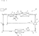
- Fig. 1 is a circuit diagram schematically showing a configuration of a refrigerant circuit of a refrigeration cycle apparatus 100 according to Embodiment 1 of the invention.
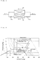
- Fig. 2 is a schematic vertical cross-sectional view showing a cross-sectional configuration of a compressor 1.
- Fig. 3 is a diagram illustrating an exemplary embodiment of a radiator 2.
- Fig. 4 is a P-h diagram showing transition of a refrigerant during a cooling operation of the refrigeration cycle apparatus 100.
- the circuit configuration and operations of the refrigeration cycle apparatus 100 will be described with reference to Figs. 1 through 4 .
- the refrigeration cycle apparatus 100 of this embodiment is used as a device having a refrigeration cycle for circulating a refrigerant, such as a refrigerator, a freezer, an automatic vending machine, an air-conditioning device (e.g., air-conditioning devices for home and industrial uses, and for vehicles), and a water heater.
- a refrigerant such as a refrigerator, a freezer, an automatic vending machine, an air-conditioning device (e.g., air-conditioning devices for home and industrial uses, and for vehicles), and a water heater.
- a refrigerant such as a refrigerator, a freezer, an automatic vending machine, an air-conditioning device (e.g., air-conditioning devices for home and industrial uses, and for vehicles), and a water heater.
- the refrigeration cycle apparatus 100 includes at least the compressor 1, the radiator 2, an internal heat exchanger 3, a first expansion valve 4 serving as a pressure reducing device, an evaporator 5, and a second expansion valve serving as a pressure reducing device.
- the compressor 1, the radiator 2, a primary passage of the internal heat exchanger 3, the first expansion valve 4, and the evaporator 5 are connected to one another by pipes so as to form a main refrigerant circuit.
- the compressor 1, the radiator 2, a second expansion valve 6, a secondary passage of the internal heat exchanger 3, and an injection port 113 of the compressor 1 are connected to one another by pipes so as to form an injection circuit.
- the refrigeration cycle apparatus 100 includes a controller 50 that controls the overall control of the refrigeration cycle apparatus 100.
- the refrigeration cycle apparatus 100 uses carbon dioxide (CO 2 ) as a refrigerant.
- CO 2 carbon dioxide
- Carbon dioxide has characteristics such as zero ozone depleting potential and a small global warming potential as compared with conventional chlorofluorocarbon based refrigerants.
- the refrigerant is not limited to carbon dioxide, and other single refrigerants, mixed refrigerants (for example, a mixed refrigerant of carbon dioxide and diethyl ether), or the like that undergoes transition to a supercritical state may be used as the refrigerant.
- the compressor 1 compresses the refrigerant, which is suctioned by an electric motor 102 and a drive shaft 103 driven by the electric motor 102, and turns the refrigerant into a high-temperature high-pressure state.
- This compressor 1 may preferably include a capacity-controllable inverter compressor, for example. It is to be noted that the details of the compressor 1 is described later with reference to Fig. 2 .
- the radiator 2 is configured to exchange heat between the refrigerant flowing through the main refrigerant circuit and a heat medium (e.g., air and water) such that the refrigerant transfers its heat to the heat medium.
- the radiator 2 exchanges heat between the air supplied by an air-sending device (not shown) and the refrigerant, for example.
- This radiator 2 includes a heat transfer pipe and a fin (not shown) for providing an increased heat transfer area between the refrigerant flowing through the heat transfer pipe and air, and exchanges heat between the refrigerant and air (outdoor air) so as to serve as a condenser or a gas cooler.
- the radiator 2 may not completely gasify or vaporize the refrigerant, and may turn the refrigerant into a two-phase mixture of gas and liquid (two-phase gas-liquid refrigerant).
- the radiator 2 is divided into a plurality of units, such as a first radiator 2a and a second radiator 2b such that the refrigerant is divided into portions that flow in parallel through the respective first radiator 2a and second radiator 2b.
- a solenoid valve 41a and a solenoid valve 41b serving as opening and closing devices may be provided at a refrigerant inlet and a refrigerant outlet, respectively, of one of the divided units of the radiator 2, namely, the second radiator 2b.
- the solenoid valve 41a and the solenoid valve 41b may be closed, if necessary, so as to block the refrigerant from flowing through the second radiator 2b and thereby to reduce the heat transfer area of the radiator 2.
- Fig. 3 illustrates an example in which the radiator 2 is divided into two units, the radiator 2 may be divided into three or more units.
- the internal heat exchanger 3 is configured to exchange heat between a refrigerant (primary side) flowing through the main refrigerant circuit between the radiator 2 and the first expansion valve 4, and a refrigerant (secondary side) flowing through the injection circuit between the second expansion valve 6 and the injection port 113 of the compressor 1.
- the internal heat exchanger 3 has one refrigerant inlet connected to a pipe 13 through which one portion (secondary-side refrigerant) of the refrigerant that has been branched after flowing out of the radiator 2 flows, and has the other refrigerant inlet connected to a pipe 12 through which the other portion (primary-side refrigerant) that has been branched after flowing out of the radiator 2 flows.
- the second expansion valve 6 is provided in the pipe 13 so as to reduce the pressure of the one portion of the refrigerant flowing into the internal heat exchanger 3. Accordingly, the temperature of the secondary-side refrigerant becomes lower than that of the primary-side refrigerant, and hence the primary-side refrigerant is cooled and the secondary-side refrigerant is heated in the internal heat exchanger 3.
- the first expansion valve 4 is configured to reduce the pressure of the refrigerant flowing through the main refrigerant circuit and expands the refrigerant, and may include a valve whose opening degree is variably controllable, such as an electronic expansion valve.
- the evaporator 5 is configured to exchange heat between the refrigerant flowing through the main refrigerant circuit and a heat medium (e.g., air and water) such that the refrigerant receives heat from the heat medium.
- the radiator 2 is configured to exchange heat with the air supplied by an air-sending device (not shown) and the refrigerant, for example.
- This evaporator 5 includes a heat transfer pipe and a fin (not shown) for increasing the heat transfer area between the refrigerant flowing through the heat transfer pipe and air, and exchanges heat between the refrigerant and air (outdoor air) so as to evaporate and gasify(vaporize) the refrigerant.
- the second expansion valve 6 is configured to reduce the pressure of the refrigerant flowing through the injection circuit and expands the refrigerant, and may include a valve whose opening degree is variably controllable, such as an electronic expansion valve.
- Refrigerant pipes for connecting respective components in the main refrigerant circuit include a discharge pipe 16 of the compressor 1, a pipe 11 provided on a refrigerant outlet side of the radiator 2, the pipe 12 provided on a primary-side inlet of the internal heat exchanger 3, and a pipe 14 provided on a refrigerant outlet side of the evaporator 5.
- Refrigerant pipes in the injection circuit include the pipe 13 branched from the pipe 11 and connected to a secondary-side inlet of the internal heat exchanger 3, and a pipe 15 connecting a secondary-side outlet of the internal heat exchanger 3 to the injection port 113 of the compressor 1.
- the refrigeration cycle apparatus 100 includes a pressure sensor 21 serving as first pressure detecting means, a temperature sensor 31 serving as first temperature detecting means, a pressure sensor 22 serving as second pressure detecting means, a temperature sensor 23 serving as temperature detecting means, and a temperature sensor 32 serving as second temperature detecting means.
- Information (pressure information and temperature information) detected by these various detecting means is sent to the controller 50 so as to be used for controlling the components of the refrigeration cycle apparatus 100.
- the pressure sensor 21 is provided in the pipe 11 at the refrigerant outlet of the radiator 2, and is configured to detect the refrigerant pressure on the refrigerant outlet side of the radiator 2.
- the temperature sensor 31 is provided in the vicinity of the radiator 2, such as the outer surface of the radiator 2, and is configured to detect the temperature of the heat medium, such as air, entering the radiator 2.
- the temperature sensor 31 may include a thermistor, for example.
- the pressure sensor 22 is provided in the pipe 14 at the refrigerant outlet of the evaporator 5, and is configured to detect the refrigerant pressure on the refrigerant outlet side of the evaporator 5.
- the temperature sensor 23 is provided in the pipe 14 at the refrigerant outlet of the evaporator 5, and is configured to detect the refrigerant temperature on the refrigerant outlet side of the evaporator 5.
- the temperature sensor 23 may include a thermistor, for example.
- the temperature sensor 32 is provided in the vicinity of the evaporator 5, such as the outer surface of the evaporator 5, and is configured to detect the temperature of the heat medium, such as air, entering the evaporator 5.
- the temperature sensor 32 may include a thermistor, for example.
- the installation positions of the pressure sensor 21, the temperature sensor 31, the pressure sensor 22, the temperature sensor 23, and the temperature sensor 32 are not limited to the positions shown in Fig. 1 , and these components may be installed in any positions where the pressure sensor 21, the temperature sensor 31, the pressure sensor 22, the temperature sensor 23, and the temperature sensor 32 can detect the pressure of the refrigerant that has flowed out of the radiator 2, the temperature of the heat medium entering the radiator 2, the pressure of the refrigerant that has flowed out of the evaporator 5, the temperature of the refrigerant that has flowed out of the evaporator 5, and the temperature of the heat medium entering the evaporator 5, respectively.
- controller 50 controls the drive frequency of the compressor 1, the rotational speed of the air-sending devices (not shown) provided in the vicinity of the radiator 2 and the evaporator 5, the opening degree of the first expansion valve 4, the opening degree of the second expansion valve 6, and opening and closing of the solenoid valves 41a and 41b if they are provided.
- the electric motor 102 serving as the driving force
- the drive shaft 103 configured to be rotated and driven by the electric motor 102
- an oscillating scroll 104 attached to a distal end of the drive shaft 103 and configured to be rotated and driven together with the drive shaft 103
- a fixed scroll 105 disposed above the oscillating scroll 104 and having a lap that engages a lap of the oscillating scroll 104, etc.
- an inflow pipe 106 that allows the refrigerant to flow into the shell 101
- an outflow pipe 112 connected to the discharge pipe 16 and an injection pipe 114 connected to the pipe 15 are connected to the shell 101.
- a low-pressure space 107 communicating with the inflow pipe 106 is formed at the outermost peripheries of the laps of the oscillating scroll 104 and the fixed scroll 105.
- a high-pressure space 111 communicating with the outflow pipe 112 is formed at the inner upper part of the shell 101.
- the lap of the oscillating scroll 104 and the lap of the fixed scroll engage with each other so as to form a plurality of compression chambers (e.g., a compression chamber 108 and a compression chamber 109) whose capacities vary relatively.
- the compression chamber 109 illustrates a compression chamber formed at substantially center portions of the oscillating scroll 104 and the fixed scroll 105.
- the compression chamber 108 illustrates a compression chamber formed during midway of a compression process, on the outer side of the compression chamber 109.
- An outflow port 110 communicating between the compression chamber 109 and the high-pressure space 111 is provided substantially at the center of the fixed scroll 105.
- the injection port 113 communicating between the compression chamber 108 and the injection pipe 114 is provided at a midway position of the compression process of the fixed scroll 105.
- an Oldham ring (not shown) for preventing rotation movement of the oscillating scroll 104 during eccentric turning movement is arranged in the shell 101. This Oldham ring provides the function of stopping the rotation movement and a function of allowing orbital motion of the oscillating scroll 104.
- the fixed scroll 105 is fixed inside the shell 101.
- the oscillating scroll 104 performs orbital motion relative to the fixed scroll 105 without performing the rotation movement.
- the electric motor 102 includes at least a stator that is fixed inside the shell 101, and a rotor that is arranged so as to be rotatable inside an inner peripheral surface of the stator and that is fixed to the drive shaft 103.
- the stator has a function of rotatably driving the rotor when the stator is energized.
- the rotor has a function of being rotatably driven and rotating the drive shaft 103 when the stator is energized.
- the oscillating scroll 104 is mounted to the distal end of the drive shaft 103 such that the oscillating scroll 104 performs the orbital motion.
- the compression chamber moves toward the center while the volume of the compression chamber is reduced by the turning movement of the oscillating scroll 104, and hence the refrigerant is compressed.
- the refrigerant flowing through the pipe 15 of the injection circuit flows into the compressor 1 through the injection pipe 114. Meanwhile, the refrigerant flowing through the pipe 14 flows into the compressor 1 through the inflow pipe 106.
- the refrigerant that has flowed from the inflow pipe 106 flows into the low-pressure space 107, and is trapped inside the compression chamber so at to be gradually compressed. Then, when the compression chamber reaches the compression chamber 108 at the midway position of the compression process, the refrigerant flows into the compression chamber 108 from the injection port 113.
- the refrigerant that has flowed in from the injection pipe 114 and the refrigerant that has flowed in from the inflow pipe 106 are mixed in the compression chamber 108. Then, the mixed refrigerant is gradually compressed and reaches the compression chamber 109. The refrigerant that has reached the compression chamber 109 passes through the outflow port 110 and the high-pressure space 111, is discharged outside the shell 101 through the outflow pipe 112, and passes through the discharge pipe 16.
- Embodiment 1 a cooling operation in which the radiator 2 is used as an outdoor heat exchanger and the evaporator 5 is used as an indoor heat exchanger is described. That is, the refrigerant exchanges heat with the outdoor air in the radiator 2, and exchanges heat with the indoor air in the evaporator 5.
- a low-pressure refrigerant is suctioned into the compressor 1.
- the low-pressure refrigerant that has been suctioned into the compressor 1 is compressed into a medium-pressure refrigerant (from a state A to a state H).
- an intermediate-pressure refrigerant (a state G) is injected from the pipe 15 of the injection circuit so as to be mixed in the compressor 1 (a state I).
- the mixed refrigerant is further compressed into a high-temperature high-pressure refrigerant (from the state I to a state B).
- the high-temperature high-pressure refrigerant that has been compressed in the compressor 1 is discharged from the compressor 1 and flows into the radiator 2.
- the refrigerant that has flowed into the radiator 2 exchanges heat with the outdoor air supplied to the radiator 2 so as to reject heat.
- the refrigerant transfers heat to the outdoor air so as to become a low-temperature high-pressure refrigerant (the state B to a state C).
- This low-temperature high-pressure refrigerant flows out of the radiator 2, and one portion of the refrigerant is subjected to pressure reduction at the second expansion valve 6 so as to become an intermediate-pressure refrigerant, and flows into the internal heat exchanger 3 through the pipe 13.
- the other one of the diverged portions of the refrigerant that has flowed out of the radiator 2 flows into the internal heat exchanger 3 through the pipe 12 without changing the state thereof.
- the refrigerants that have flowed into the internal heat exchanger exchange heat with each other.
- One of the refrigerants is heated (from a state F to a state G), and is injected into the compressor 1.
- the other one of the refrigerants is cooled (from the state C to a state D), and flows into the first expansion valve 4.
- the refrigerant that has flowed into the first expansion valve 4 is subjected to pressure reduction and is turned low in temperature so as to be in a low-quality state (from the state D to a state E).
- the refrigerant that has flowed out of the evaporator 5 is suctioned into the first compressor 1, again. By repeatedly performing the operation described above, the heat of the indoor air is transferred to the outdoor air, so that the room is cooled.
- the compressor 1 is a type of compressor in which its capacity is controlled by controlling its rotation speed with an inverter.
- the cooling capacity is controlled by the rotation speed of the compressor 1.
- the flow rate of the refrigerant flowing through the evaporator 5 is adjusted by adjusting the opening degree of the first expansion valve 4 on the basis of the degree of superheat at a refrigerant outlet of the evaporator 5.
- the degree of superheat at the refrigerant outlet of the evaporator 5 is calculated from a saturation temperature of the refrigerant, which is calculated by the controller 50 on the basis of the pressure detected by the pressure sensor 22, and a temperature detected by the temperature sensor 23.
- the degree of superheat of the evaporator 5 may preferably be in a range of about 2 through 10°C.
- the refrigerant that has flowed out of the radiator 2 and that is to flow into the first expansion valve 4 is further cooled in the internal heat exchanger 3, even if a refrigerant that enters a supercritical state on the high-pressure side, such as carbon dioxide, is used, it is possible to increase the enthalpy difference of the refrigerant in the evaporator 5.
- the intermediate-pressure refrigerant heated in the internal heat exchanger 3 is injected in the middle of the compression stroke of the compressor 1. Accordingly, in the refrigeration cycle apparatus 100, the refrigerant is cooled at an intermediate pressure in the compressor 1. This makes it possible to prevent the discharge temperature of the compressor 1 from becoming too high, and thus to prevent a large load from being placed on refrigerant oil, a sealing surface, etc.
- the refrigeration cycle apparatus 100 can provide the following effect by injecting the refrigerant in the middle of the compression stroke of the compressor 1.
- Gdis Gsuc + Ginj , where Gsuc represents the flow rate of the refrigerant suctioned into the compressor 1 from the low-pressure side; Ginj represents the flow rate of the injected refrigerant; and Gdis represents the flow rate of the refrigerant discharged from the compressor 1.
- the flow rate of the refrigerant entering the radiator 2 is increased by injecting the refrigerant into the compressor 1. Therefore, the amount of heat transfer in the radiator 2 is increased.
- the overload conditions are those where the air temperature is high both inside and outside the room in summer and the like.
- the overload conditions may be those where the outdoor air temperature is about 45°C and the indoor air temperature is about 35°C. A cooling operation at such outdoor air temperature and indoor air temperature will be described.
- FIG. 4 An example of a state of the cooling operation under overload conditions (in the case where injection is not performed) is indicated by a broken line in the P-h diagram of Fig. 4 .
- the high-pressure-side pressure is 11.5 MPa. Since the outdoor air temperature is as high as 45°C, the refrigerant in the radiator 2 cannot be cooled sufficiently, and its temperature increases to as high as about 49°C. Further, when the high-pressure-side pressure enters a supercritical state, in the case where the high-pressure-side pressure is not sufficiently high due to the effects of isotherms, the heat transfer capacity is low, and the enthalpy difference is reduced in the evaporator. On the other hand, in the evaporator 5, since the indoor air temperature is as high as 35°C, the evaporating temperature increases to as high as about 20°C (the saturation pressure of about 5.5 MPa).
- the intermediate pressure PM is about 8.0 MPa, which is higher than the critical point pressure of 7.38 MPa.
- the refrigeration cycle apparatus 100 is configured to, when operated under overload conditions, inject the intermediate-pressure refrigerant heated by the internal heat exchanger 3 in the middle of the compression stroke of the compressor 1, and divide the radiator 2 so as to reduce the heat transfer area.
- the high-pressure-side pressure in the radiator 2 is increased so as to increase the amount of heat transfer and thus increase the cooling capacity.
- the radiator 2 is divided into the first radiator 2a and the second radiator 2b such that the refrigerant is divided into portions that flow in parallel through the respective first radiator 2a and second radiator 2b.
- the solenoid valve 41a and the solenoid valve 41b are closed such that the refrigerant flows only into the first radiator 2a.
- the heat transfer area is reduced.
- the high-pressure-side pressure is further increased.
- the refrigeration cycle apparatus 100 is configured to increase the high-pressure-side pressure and thus increase the amount of heat transfer by injection of the refrigerant in the middle of the compression stroke of the compressor 1 and by reduction of the heat transfer area of the radiator 2.
- the refrigerant in the supercritical state has the properties that, on the isotherms, the higher the pressure is, the lower the enthalpy is. In particular, the higher the temperature is, the greater the variation of the enthalpy relative to the pressure is.
- the refrigerant outlet temperature in the radiator 2 is dependent on the air inlet temperature. Accordingly, the more the conditions causes the air inlet temperature of the radiator 2, that is, the outdoor air temperature to rise, the more the amount of heat transfer is increased by the increase of the high-pressure-side pressure.
- the refrigerant inlet enthalpy of the evaporator 5 decreases, and the refrigerant enthalpy difference in the evaporator 5 increases, making it possible to increase the cooling capacity.
- Fig. 5 is a flowchart showing a flow of a specific control process of the second expansion valve 6, the solenoid valve 41a, and the solenoid valve 41b, which is performed by the controller 50. Next, a specific method of operating the second expansion valve 6, the solenoid valve 41a, and the solenoid valve 41b will be described with reference to Fig. 5 .
- the controller 50 detects a high-pressure-side pressure PH on the basis of information from the pressure sensor 21, and detects a low-pressure-side pressure PL on the basis of information from the pressure sensor 22 (Step 201).
- the controller 50 calculates the intermediate pressure PM from the high-pressure-side pressure PH and the low-pressure-side pressure PL (Step 202).
- This intermediate pressure PM is calculated from the above equation (2).
- another pressure sensor may be provided in the pipe 15 of the injection circuit so as to directly detect the intermediate pressure PM.
- the controller 50 determines whether the intermediate pressure PM is higher than a critical point pressure PCR (Step 203). It should be noted that, as mentioned above, the critical point pressure PCR of carbon dioxide is about 7.38 MPa. If the intermediate pressure PM is determined to be higher than the critical point pressure PCR (Step 203; Yes), the controller 50 determines whether the solenoid valve 41a and the solenoid valve 41b are open (Step 204). If the solenoid valve 41a and the solenoid valve 41b are open (Step 204; Yes), the controller 50 closes the solenoid valve 41a and the solenoid valve 41b so as to cause the refrigerant to flow only into the first radiator 2a (Step 205). After that, the controller 50 sets a target high-pressure-side pressure PHM (Step 206). This target high-pressure-side pressure PHM will be described below.
- the controller 50 After setting the target high-pressure-side pressure PHM, the controller 50 detects the high-pressure-side pressure PH again (step 207). Then, the controller 50 determines whether the high-pressure-side pressure PH is higher than the target high-pressure-side pressure PHM (Step 208). If the high-pressure-side pressure PH is higher than the target high-pressure-side pressure PHM (Step 208; Yes), the controller 50 operates so as to reduce the opening degree of the second expansion valve 6 (Step 209). On the other hand, if the high-pressure-side pressure PH is lower than the target high-pressure-side pressure PHM (Step 208; No), the controller 50 operates so as to increase the opening degree of the second expansion valve 6 (Step 210). After that, the process returns to Step 201.
- Step 203 determines whether the intermediate pressure PM is determined to be lower than the critical point pressure PCR (Step 203; No). If the solenoid valve 41a and the solenoid valve 41b are closed (Step 211; Yes), the controller 50 opens the solenoid valve 41a and the solenoid valve 41b so as to allow the refrigerant to flow into the second radiator 2b (Step 212). After that, the process returns to Step 201.
- the controller 50 repeats the above steps so as to perform an operation of increasing the cooling capacity.
- Fig. 6 is a graph showing a relationship between the capacity rate and the heat transfer area of a radiator 2 with respect to the injection rate.
- Fig. 7 is a graph showing a relationship between the COP rate and the heat transfer area of the radiator 2 with respect to the injection rate.
- Fig. 8 is a graph showing a relationship between the high-pressure-side pressure and the heat transfer area of the radiator 2 with respect to the injection rate.
- the injection rate is defined as the rate of the flow rate Ginj of the injected refrigerant to the flow rate Gsuc of the refrigerant that is suctioned into the compressor 1 from the low-pressure side. That is, the injection rate is defined as Ginj/Gsuc.
- the references of the capacity and COP are those obtained in the case where the heat transfer area is set to 100% without dividing the radiator 2 and no injection is performed.
- the refrigeration cycle apparatus 100 is especially effective under overload conditions where the indoor air temperature is high, it is necessary to operate the refrigeration cycle apparatus 100 so as to lower the indoor air temperature by increasing the cooling capacity as much as possible. Accordingly, as can be seen from Figs. 6 through 8 , when setting the heat transfer area of the radiator 2 to about 85%, the injection rate to about 0.15, and the high-pressure-side pressure to about 14.2 MPa, compared with the case under operational conditions where the heat transfer area is 100% and the injection rate is 0, since the COP becomes 100%, the COP is not reduced while the cooling capacity is increased by about 35%.
- the heat transfer area of the first radiator 2a be set to about 85% of that of the entire radiator 2, and the target high-pressure-side pressure PHM be set to 14.2 MPa. It should be noted that the above values of the rate of the heat transfer area of the radiator 2 and the target high-pressure-side pressure PHM are especially preferred values, and the values of the rate of the heat transfer area and the target high-pressure-side pressure PHM are not limited to these values.
- the refrigeration cycle apparatus 100 according to Embodiment 1 can increase the cooling capacity under overload conditions where the indoor air temperate is high, and therefore can lower the indoor temperature more quickly.
- the control for increasing the cooling capacity involves detecting the high-pressure-side pressure and the low-pressure-side pressure.
- the control for increasing the cooling capacity may be performed on the basis of the inlet air temperature of the radiator 2 detected by the temperature sensor 31 and the inlet air temperature of the evaporator 5 detected by the temperature sensor 32, for example. This is because when the inlet air temperature of the radiator 2 is high, the refrigerant outlet temperature of the radiator 2 naturally becomes high, and the cooling capacity need to be increased. This is also because when the inlet air temperature of the evaporator becomes high, the evaporating temperature of the refrigerant naturally becomes high, and thus there is a relationship between the indoor air temperature and the low-pressure-side pressure.
- Embodiment 2 While, in Embodiment 1, the cooling capacity is increased when the intermediate pressure is in a supercritical state, in Embodiment 2, the cooling capacity is increased when starting the refrigeration cycle apparatus.
- the basic configuration and operations of a refrigeration cycle apparatus of Embodiment 2 are the same as those of the refrigeration cycle apparatus 100 of Embodiment 1. It should be noted that Embodiment 2 mainly describes the differences from the above Embodiment 1. In Embodiment 2, the same reference symbols as those used in Embodiment 1 will be used.
- Fig. 9 is a flowchart showing a flow of a specific control process of the second expansion valve 6, the solenoid valve 41a, and the solenoid valve 41b, which is performed by the controller 50 of the refrigeration cycle apparatus according to Embodiment 2 of the invention.
- a specific method of operating the second expansion valve 6, the solenoid valve 41a, and the solenoid valve 41b will be described with reference to Fig. 9 .
- the controller 50 When the refrigeration cycle apparatus starts a cooling operation, the controller 50 first sets a target indoor air temperature Tam (Step 301). The target indoor air temperature Tam will be described below. Then, the controller 50 detects an indoor air temperature Ta on the basis of information from the temperature sensor 32 (Step 302). The controller 50 determines whether the indoor air temperature Ta is higher than the target indoor air temperature Tam (Step 303). If the indoor air temperature Ta is higher than the target indoor air temperature Tam (Step 303; Yes), the controller 50 determines whether the solenoid valve 41a and the solenoid valve 41b are open (Step 304).
- Step 304 If the solenoid valve 41a and the solenoid valve 41b are open (Step 304; Yes), the controller 50 closes the solenoid valve 41a and the solenoid valve 41b so as to cause the refrigerant to flow only into the first radiator 2a (Step 305). After that, the controller 50 sets a target high-pressure-side pressure PHM (Step 306).
- the controller 50 After setting the target high-pressure-side pressure PHM, the controller 50 detects the high-pressure-side pressure PH (step 307). Then, the controller 50 determines whether the high-pressure-side pressure PH is higher than the target high-pressure-side pressure PHM (Step 308). If the high-pressure-side pressure PH is higher than the target high-pressure-side pressure PHM (Step 308; Yes), the controller 50 operates so as to reduce the opening degree of the second expansion valve 6 (Step 309). On the other hand, if the high-pressure-side pressure PH is lower than the target high-pressure-side pressure PHM (Step 308; No), the controller 50 operates so as to increase the opening degree of the second expansion valve 6 (Step 310). After that, the process returns to Step 302.
- the controller 50 determines whether the solenoid valve 41a and the solenoid valve 41b are closed (Step 311). If the solenoid valve 41a and the solenoid valve 41b are closed (Step 311; Yes), the controller 50 opens the solenoid valve 41a and the solenoid valve 41b so as to allow the refrigerant to flow into the second radiator 2b (Step 312). After that, the process switches to regular control (Step 313).
- regular control indicates a usual cooling operation that is performed in accordance with a command from the controller 50.
- the target indoor air temperature Tam described above may be 27°C, which is a standard indoor air temperature in a cooling operation, for example.
- the refrigeration cycle apparatus can increase the cooling capacity by increasing the high-pressure-side pressure when the indoor temperature is higher than a standard indoor air temperature in a cooling operation, and therefore can lower the indoor air temperature more quickly. This makes it possible to provide users with a higher level of comfort.
- the target high-pressure-side pressure PHM, the percentage of the heat transfer area of the first radiator 2a to the heat transfer area of the entire radiator 2, etc. may be determined in the same manner described in Embodiment 1. Further, the refrigeration cycle apparatus according to Embodiment 2 is configured such that, if the indoor air temperature becomes lower than the target indoor air temperature in Step 303, the process switches to regular control in Step 313. Accordingly, this prevents the indoor air from being excessively cooled due to an excessively increased high-pressure-side pressure, and prevents electric power from being wasted.
- a temperature sensor may separately be provided between the refrigerant outlet of the first expansion valve 4 and the refrigerant inlet of the evaporator 5 in place of the pressure sensor 22 so as to calculate the low-pressure-side pressure from a saturation temperature detected by this temperature sensor.
- Embodiment 1 and Embodiment 2 adjust the opening degree of the second expansion valve 6 in accordance with the target value of the high-pressure-side pressure, even under conditions, such as overload condition, where the intermediate pressure enters a supercritical state and hence the saturation temperature cannot be calculated, it is possible to reliably increase the cooling capacity.
- a four-way valve or the like for switching between the refrigerant passages may be provided, for example, such that a heating operation is executable in which the radiator 2 heats the indoor air.
- a heating operation is executable, the heating capacity can be increased by performing the operational actions described in Embodiment 1 and Embodiment 2.
- two-way valves that is, the solenoid valve 41a and the solenoid valve 41b are provided in order to block the refrigerant from flowing through the second radiator 2b.
- the invention is not limited to these embodiments, and any means for blocking the refrigerant can be used.
- a check valve may be provided at the refrigerant outlet side of the second radiator 2b.
- the radiator 2 and the evaporator 5 serve as heat exchangers that exchange heat between a refrigerant and air.
- the invention is not limited to these embodiments.
- the radiator 2 and the evaporator 5 may be heat exchangers that exchange heat between a refrigerant and a heat medium other than air, such as water and brine.
- the high-pressure-side pressure is increased by performing an injection into the compressor 1 and by reducing the heat transfer area of the radiator 2.
- the invention is not limited to these embodiments.
- the air volume of a fan (not shown) that forces the air to pass over the outer surface of the radiator 2 may be reduced, or the flow rate of a pump (not shown) that circulates another heat medium such as water and brine may be reduced.
- the refrigerant of an intermediate pressure is injected into the compression chamber 108 of the compressor 1.
- the compressor 1 may have a two-stage compression mechanism, and the refrigerant may be injected into a path connecting between a low-stage compression chamber and a high-stage compression chamber.
- the compressor 1 may include a plurality of compressors so as to perform two-stage compression.
Description
- The present invention generally relates to a refrigeration cycle apparatus using a refrigerant that undergoes transition into a supercritical state, the refrigeration cycle apparatus having an injection circuit.
- As known vapor compression refrigeration cycles that use a refrigerant such as carbon dioxide (CO2) in its supercritical region, there is a vapor compression refrigeration cycle in which a refrigerant that has flowed out of a radiator is branched such that one portion of the refrigerant is subjected to pressure reduction in a pressure reducing device, flows through a cooler so as to exchange heat with the other portion of the refrigerant that has flowed out of the radiator, and is injected in the middle of a compression stroke of a compressor (see Japanese patent number
4207235 Claim 1,Figure 1 , for example). The vapor compression refrigeration cycle disclosed in Japanese patent number4207235 - Document
US 2004/0250568 A1 discloses a system for regulating the high Pressure component of an economized refrigeration system by regulating the amount of refrigerant in the high pressure component of the system with an interstage accumulator positioned between an economizer heat exchanger and a compressor. This document describes the adjustment of a second expansion valve for controlling high-pressure side pressure and represents the closest prior art to the present invention. - Document
WO 2008/130358 A1 discloses a refrigerant vapor compression system which includes a refrigerant-to-refrigerant heat exchanger economizer and a flash tank disposed in series refrigerant flow relationship in the refrigerant circuit intermediate a refrigerant heat rejection heat exchanger and a refrigerant heat absorption heat exchanger. A primary expansion valve is interdisposed in the refrigerant circuit upstream of the refrigerant heat absorption heat exchanger and a secondary expansion valve is interdisposed in the refrigerant circuit upstream of the flash tank. The flash tank functions as a refrigerant charge storage reservoir wherein refrigerant expanded from a supercritical pressure to subcritical pressure separates into liquid and vapor phases. A refrigerant vapor bypass line is provided to return refrigerant vapor from the flash tank to the refrigerant circuit downstream of the refrigerant heat absorption heat exchanger. The primary expansion valve and a flow control valve interdisposed in the refrigerant vapor bypass provide refrigerant charge management
JP2007170683A - However, the known vapor compression refrigeration cycle has the following problem.
- Under overload conditions where inlet air temperatures of the radiator and an evaporator become high, a high-pressure-side pressure and a low-pressure-side pressure become high. As a result, the pressure of one of the refrigerant that has been branched from the radiator and has been subjected to pressure reduction also becomes high, and may enter a supercritical state. In a vapor compression refrigeration cycle as described in
Patent Literature 1, under overload conditions, the degree of superheat of the one portion of the refrigerant at the outlet of the cooler cannot be calculated, which may make it impossible to control the specific enthalpy of the other portion of the refrigerant. Further, if the one portion of the refrigerant is in a supercritical state, no latent heat change occurs during the heating process of the refrigerant, and therefore effect of cooling the other portion of the refrigerant in the cooler cannot be expected much. - The invention has been made to overcome the above problem and an object thereof is to provide a refrigeration cycle apparatus that is capable of increasing the cooling capacity even under overload conditions in a refrigeration cycle apparatus that uses a refrigerant which undergoes transition to a supercritical state and in which the high-pressure side enters a supercritical state.
- A refrigeration cycle apparatus according to the invention is defined by appended
independent claim 1. - A refrigeration cycle apparatus according to the invention as defined by appended
independent claim 1, can adjust a high-pressure-side pressure of a refrigerant flowing through a main refrigerant circuit by controlling an opening degree of a second pressure reducing device and a heat transfer area of a radiator. Therefore, even under operational conditions where a cooling operation is performed under overload conditions and an intermediate pressure becomes supercritical, for example, the refrigeration cycle apparatus can reliably increase the high-pressure-side pressure, and thereby can increase the cooling capacity. -
- [
Fig. 1] Fig. 1 is a circuit diagram schematically showing a configuration of a refrigerant circuit of a refrigeration cycle apparatus according toEmbodiment 1 of the invention. - [
Fig. 2] Fig. 2 is a schematic vertical cross-sectional view showing a cross-sectional configuration of a compressor. - [
Fig. 3] Fig. 3 is a diagram illustrating an exemplary embodiment of a radiator. - [
Fig. 4] Fig. 4 is a P-h diagram showing transition of a refrigerant during a cooling operation of the refrigeration cycle apparatus according toEmbodiment 1 of the invention. - [
Fig. 5] Fig. 5 is a flowchart showing a flow of a specific control process of a second expansion valve and a solenoid valve, which is performed by a controller of the refrigeration cycle apparatus according toEmbodiment 1 of the invention. - [
Fig. 6] Fig. 6 is a graph showing a relationship between the capacity rate and the heat transfer area of a radiator with respect to the injection rate. - [
Fig. 7] Fig. 7 is a graph showing a relationship between the COP rate and the heat transfer area of the radiator with respect to the injection rate. - [
Fig. 8] Fig. 8 is a graph showing a relationship between the high-pressure-side pressure and the heat transfer area of the radiator with respect to the injection rate. - [
Fig. 9] Fig. 9 is a flowchart showing a flow of a specific control process of a second expansion valve and a solenoid valve, which is performed by a controller of the refrigeration cycle apparatus according toEmbodiment 2 of the invention. - Embodiments of the invention will be described below with reference to the drawings.
-
Fig. 1 is a circuit diagram schematically showing a configuration of a refrigerant circuit of arefrigeration cycle apparatus 100 according toEmbodiment 1 of the invention.Fig. 2 is a schematic vertical cross-sectional view showing a cross-sectional configuration of acompressor 1.Fig. 3 is a diagram illustrating an exemplary embodiment of aradiator 2.Fig. 4 is a P-h diagram showing transition of a refrigerant during a cooling operation of therefrigeration cycle apparatus 100. The circuit configuration and operations of therefrigeration cycle apparatus 100 will be described with reference toFigs. 1 through 4 . - The
refrigeration cycle apparatus 100 of this embodiment is used as a device having a refrigeration cycle for circulating a refrigerant, such as a refrigerator, a freezer, an automatic vending machine, an air-conditioning device (e.g., air-conditioning devices for home and industrial uses, and for vehicles), and a water heater. In particular, great advantages are enjoyed in a refrigeration cycle apparatus using a refrigerant that enters a supercritical state on a high-pressure side. It should be noted that the dimensional relationships of components inFig. 1 and other subsequent drawings may be different from the actual ones. Also, inFig. 1 and other subsequent drawings, components applied with the same reference signs correspond to the same or equivalent components. This is common through the full text of the description. Further, forms of components described in the full text of the description are mere examples, and the components are not limited to the described forms of components Resulting embodiments fall into the scope of the present invention as long as they comprise at least all features of appendedindependent claim 1. - The
refrigeration cycle apparatus 100 includes at least thecompressor 1, theradiator 2, aninternal heat exchanger 3, a first expansion valve 4 serving as a pressure reducing device, anevaporator 5, and a second expansion valve serving as a pressure reducing device. Thecompressor 1, theradiator 2, a primary passage of theinternal heat exchanger 3, the first expansion valve 4, and theevaporator 5 are connected to one another by pipes so as to form a main refrigerant circuit. Also, thecompressor 1, theradiator 2, asecond expansion valve 6, a secondary passage of theinternal heat exchanger 3, and aninjection port 113 of thecompressor 1 are connected to one another by pipes so as to form an injection circuit. Further, therefrigeration cycle apparatus 100 includes acontroller 50 that controls the overall control of therefrigeration cycle apparatus 100. - In
Embodiment 1, it is assumed that therefrigeration cycle apparatus 100 uses carbon dioxide (CO2) as a refrigerant. Carbon dioxide has characteristics such as zero ozone depleting potential and a small global warming potential as compared with conventional chlorofluorocarbon based refrigerants. However, the refrigerant is not limited to carbon dioxide, and other single refrigerants, mixed refrigerants (for example, a mixed refrigerant of carbon dioxide and diethyl ether), or the like that undergoes transition to a supercritical state may be used as the refrigerant. - The
compressor 1 compresses the refrigerant, which is suctioned by anelectric motor 102 and adrive shaft 103 driven by theelectric motor 102, and turns the refrigerant into a high-temperature high-pressure state. Thiscompressor 1 may preferably include a capacity-controllable inverter compressor, for example. It is to be noted that the details of thecompressor 1 is described later with reference toFig. 2 . - The
radiator 2 is configured to exchange heat between the refrigerant flowing through the main refrigerant circuit and a heat medium (e.g., air and water) such that the refrigerant transfers its heat to the heat medium. Theradiator 2 exchanges heat between the air supplied by an air-sending device (not shown) and the refrigerant, for example. Thisradiator 2 includes a heat transfer pipe and a fin (not shown) for providing an increased heat transfer area between the refrigerant flowing through the heat transfer pipe and air, and exchanges heat between the refrigerant and air (outdoor air) so as to serve as a condenser or a gas cooler. In some cases, theradiator 2 may not completely gasify or vaporize the refrigerant, and may turn the refrigerant into a two-phase mixture of gas and liquid (two-phase gas-liquid refrigerant). - Further, as shown in
Fig. 3 , theradiator 2 is divided into a plurality of units, such as afirst radiator 2a and asecond radiator 2b such that the refrigerant is divided into portions that flow in parallel through the respectivefirst radiator 2a andsecond radiator 2b. Asolenoid valve 41a and asolenoid valve 41b serving as opening and closing devices may be provided at a refrigerant inlet and a refrigerant outlet, respectively, of one of the divided units of theradiator 2, namely, thesecond radiator 2b. With this configuration, thesolenoid valve 41a and thesolenoid valve 41b may be closed, if necessary, so as to block the refrigerant from flowing through thesecond radiator 2b and thereby to reduce the heat transfer area of theradiator 2. It should be noted that althoughFig. 3 illustrates an example in which theradiator 2 is divided into two units, theradiator 2 may be divided into three or more units. - The
internal heat exchanger 3 is configured to exchange heat between a refrigerant (primary side) flowing through the main refrigerant circuit between theradiator 2 and the first expansion valve 4, and a refrigerant (secondary side) flowing through the injection circuit between thesecond expansion valve 6 and theinjection port 113 of thecompressor 1. Theinternal heat exchanger 3 has one refrigerant inlet connected to apipe 13 through which one portion (secondary-side refrigerant) of the refrigerant that has been branched after flowing out of theradiator 2 flows, and has the other refrigerant inlet connected to apipe 12 through which the other portion (primary-side refrigerant) that has been branched after flowing out of theradiator 2 flows. Thesecond expansion valve 6 is provided in thepipe 13 so as to reduce the pressure of the one portion of the refrigerant flowing into theinternal heat exchanger 3. Accordingly, the temperature of the secondary-side refrigerant becomes lower than that of the primary-side refrigerant, and hence the primary-side refrigerant is cooled and the secondary-side refrigerant is heated in theinternal heat exchanger 3. - The first expansion valve 4 is configured to reduce the pressure of the refrigerant flowing through the main refrigerant circuit and expands the refrigerant, and may include a valve whose opening degree is variably controllable, such as an electronic expansion valve.
- The
evaporator 5 is configured to exchange heat between the refrigerant flowing through the main refrigerant circuit and a heat medium (e.g., air and water) such that the refrigerant receives heat from the heat medium. Theradiator 2 is configured to exchange heat with the air supplied by an air-sending device (not shown) and the refrigerant, for example. Thisevaporator 5 includes a heat transfer pipe and a fin (not shown) for increasing the heat transfer area between the refrigerant flowing through the heat transfer pipe and air, and exchanges heat between the refrigerant and air (outdoor air) so as to evaporate and gasify(vaporize) the refrigerant. - The
second expansion valve 6 is configured to reduce the pressure of the refrigerant flowing through the injection circuit and expands the refrigerant, and may include a valve whose opening degree is variably controllable, such as an electronic expansion valve. - Refrigerant pipes for connecting respective components in the main refrigerant circuit include a
discharge pipe 16 of thecompressor 1, apipe 11 provided on a refrigerant outlet side of theradiator 2, thepipe 12 provided on a primary-side inlet of theinternal heat exchanger 3, and apipe 14 provided on a refrigerant outlet side of theevaporator 5. Refrigerant pipes in the injection circuit include thepipe 13 branched from thepipe 11 and connected to a secondary-side inlet of theinternal heat exchanger 3, and apipe 15 connecting a secondary-side outlet of theinternal heat exchanger 3 to theinjection port 113 of thecompressor 1. - Further, the
refrigeration cycle apparatus 100 includes apressure sensor 21 serving as first pressure detecting means, a temperature sensor 31 serving as first temperature detecting means, apressure sensor 22 serving as second pressure detecting means, atemperature sensor 23 serving as temperature detecting means, and atemperature sensor 32 serving as second temperature detecting means. Information (pressure information and temperature information) detected by these various detecting means is sent to thecontroller 50 so as to be used for controlling the components of therefrigeration cycle apparatus 100. - The
pressure sensor 21 is provided in thepipe 11 at the refrigerant outlet of theradiator 2, and is configured to detect the refrigerant pressure on the refrigerant outlet side of theradiator 2. The temperature sensor 31 is provided in the vicinity of theradiator 2, such as the outer surface of theradiator 2, and is configured to detect the temperature of the heat medium, such as air, entering theradiator 2. The temperature sensor 31 may include a thermistor, for example. Thepressure sensor 22 is provided in thepipe 14 at the refrigerant outlet of theevaporator 5, and is configured to detect the refrigerant pressure on the refrigerant outlet side of theevaporator 5. Thetemperature sensor 23 is provided in thepipe 14 at the refrigerant outlet of theevaporator 5, and is configured to detect the refrigerant temperature on the refrigerant outlet side of theevaporator 5. Thetemperature sensor 23 may include a thermistor, for example. Thetemperature sensor 32 is provided in the vicinity of theevaporator 5, such as the outer surface of theevaporator 5, and is configured to detect the temperature of the heat medium, such as air, entering theevaporator 5. Thetemperature sensor 32 may include a thermistor, for example. - It should be noted that the installation positions of the
pressure sensor 21, the temperature sensor 31, thepressure sensor 22, thetemperature sensor 23, and thetemperature sensor 32 are not limited to the positions shown inFig. 1 , and these components may be installed in any positions where thepressure sensor 21, the temperature sensor 31, thepressure sensor 22, thetemperature sensor 23, and thetemperature sensor 32 can detect the pressure of the refrigerant that has flowed out of theradiator 2, the temperature of the heat medium entering theradiator 2, the pressure of the refrigerant that has flowed out of theevaporator 5, the temperature of the refrigerant that has flowed out of theevaporator 5, and the temperature of the heat medium entering theevaporator 5, respectively. Further, thecontroller 50 controls the drive frequency of thecompressor 1, the rotational speed of the air-sending devices (not shown) provided in the vicinity of theradiator 2 and theevaporator 5, the opening degree of the first expansion valve 4, the opening degree of thesecond expansion valve 6, and opening and closing of thesolenoid valves - The configuration and operation of the
compressor 1 will be described with reference toFig. 2 . - In the
compressor 1, theelectric motor 102 serving as the driving force, thedrive shaft 103 configured to be rotated and driven by theelectric motor 102, anoscillating scroll 104 attached to a distal end of thedrive shaft 103 and configured to be rotated and driven together with thedrive shaft 103, afixed scroll 105 disposed above theoscillating scroll 104 and having a lap that engages a lap of theoscillating scroll 104, etc., are accommodated in ashell 101 constituting the outer wall of thecompressor 1. Further, aninflow pipe 106 that allows the refrigerant to flow into theshell 101, anoutflow pipe 112 connected to thedischarge pipe 16, and an injection pipe 114 connected to thepipe 15 are connected to theshell 101. - In the
shell 101, a low-pressure space 107 communicating with theinflow pipe 106 is formed at the outermost peripheries of the laps of theoscillating scroll 104 and the fixedscroll 105. A high-pressure space 111 communicating with theoutflow pipe 112 is formed at the inner upper part of theshell 101. The lap of theoscillating scroll 104 and the lap of the fixed scroll engage with each other so as to form a plurality of compression chambers (e.g., acompression chamber 108 and a compression chamber 109) whose capacities vary relatively. Thecompression chamber 109 illustrates a compression chamber formed at substantially center portions of theoscillating scroll 104 and the fixedscroll 105. Thecompression chamber 108 illustrates a compression chamber formed during midway of a compression process, on the outer side of thecompression chamber 109. - An
outflow port 110 communicating between thecompression chamber 109 and the high-pressure space 111 is provided substantially at the center of the fixedscroll 105. Theinjection port 113 communicating between thecompression chamber 108 and the injection pipe 114 is provided at a midway position of the compression process of the fixedscroll 105. Further, an Oldham ring (not shown) for preventing rotation movement of theoscillating scroll 104 during eccentric turning movement is arranged in theshell 101. This Oldham ring provides the function of stopping the rotation movement and a function of allowing orbital motion of theoscillating scroll 104. - It should be noted that the fixed
scroll 105 is fixed inside theshell 101. Also, theoscillating scroll 104 performs orbital motion relative to the fixedscroll 105 without performing the rotation movement. Further, theelectric motor 102 includes at least a stator that is fixed inside theshell 101, and a rotor that is arranged so as to be rotatable inside an inner peripheral surface of the stator and that is fixed to thedrive shaft 103. The stator has a function of rotatably driving the rotor when the stator is energized. The rotor has a function of being rotatably driven and rotating thedrive shaft 103 when the stator is energized. - Operations of the
compressor 1 will be described briefly. - When the
electric motor 102 is energized, a torque is generated between the stator and the rotor constituting theelectric motor 102, and thedrive shaft 103 is rotated. Theoscillating scroll 104 is mounted to the distal end of thedrive shaft 103 such that theoscillating scroll 104 performs the orbital motion. The compression chamber moves toward the center while the volume of the compression chamber is reduced by the turning movement of theoscillating scroll 104, and hence the refrigerant is compressed. - The refrigerant flowing through the
pipe 15 of the injection circuit flows into thecompressor 1 through the injection pipe 114. Meanwhile, the refrigerant flowing through thepipe 14 flows into thecompressor 1 through theinflow pipe 106. The refrigerant that has flowed from theinflow pipe 106 flows into the low-pressure space 107, and is trapped inside the compression chamber so at to be gradually compressed. Then, when the compression chamber reaches thecompression chamber 108 at the midway position of the compression process, the refrigerant flows into thecompression chamber 108 from theinjection port 113. - That is, the refrigerant that has flowed in from the injection pipe 114 and the refrigerant that has flowed in from the
inflow pipe 106 are mixed in thecompression chamber 108. Then, the mixed refrigerant is gradually compressed and reaches thecompression chamber 109. The refrigerant that has reached thecompression chamber 109 passes through theoutflow port 110 and the high-pressure space 111, is discharged outside theshell 101 through theoutflow pipe 112, and passes through thedischarge pipe 16. - Operation action of the
refrigeration cycle apparatus 100 will be described with reference toFig. 1 andFig. 4 . It should be noted that the symbols A through I shown inFig. 1 correspond to the symbols A through I shown inFig. 4 . Here, the highs and lows of the pressures in the refrigerant circuit and the like of therefrigeration cycle apparatus 100 is not determined in relation to a reference pressure, but relative pressures as the result of an increase in pressure by themain compressor 1 and a reduction in pressure by the first expansion valve 4 and thesecond expansion valve 6 are respectively expressed as a high pressure and a low pressure. The same applies to the highs and lows of the temperatures. Further, inEmbodiment 1, a cooling operation in which theradiator 2 is used as an outdoor heat exchanger and theevaporator 5 is used as an indoor heat exchanger is described. That is, the refrigerant exchanges heat with the outdoor air in theradiator 2, and exchanges heat with the indoor air in theevaporator 5. - First, a low-pressure refrigerant is suctioned into the
compressor 1. The low-pressure refrigerant that has been suctioned into thecompressor 1 is compressed into a medium-pressure refrigerant (from a state A to a state H). In the middle of a compression stroke of thecompressor 1, an intermediate-pressure refrigerant (a state G) is injected from thepipe 15 of the injection circuit so as to be mixed in the compressor 1 (a state I). In thecompressor 1, the mixed refrigerant is further compressed into a high-temperature high-pressure refrigerant (from the state I to a state B). The high-temperature high-pressure refrigerant that has been compressed in thecompressor 1 is discharged from thecompressor 1 and flows into theradiator 2. - The refrigerant that has flowed into the
radiator 2 exchanges heat with the outdoor air supplied to theradiator 2 so as to reject heat. Thus, the refrigerant transfers heat to the outdoor air so as to become a low-temperature high-pressure refrigerant (the state B to a state C). This low-temperature high-pressure refrigerant flows out of theradiator 2, and one portion of the refrigerant is subjected to pressure reduction at thesecond expansion valve 6 so as to become an intermediate-pressure refrigerant, and flows into theinternal heat exchanger 3 through thepipe 13. The other one of the diverged portions of the refrigerant that has flowed out of theradiator 2 flows into theinternal heat exchanger 3 through thepipe 12 without changing the state thereof. The refrigerants that have flowed into the internal heat exchanger exchange heat with each other. One of the refrigerants is heated (from a state F to a state G), and is injected into thecompressor 1. The other one of the refrigerants is cooled (from the state C to a state D), and flows into the first expansion valve 4. - The refrigerant that has flowed into the first expansion valve 4 is subjected to pressure reduction and is turned low in temperature so as to be in a low-quality state (from the state D to a state E). The refrigerant flows out of the first expansion valve 4, evaporates by receiving heat from the indoor air in the
evaporator 5 so as to be in a high-quality state while remaining low in pressure (from the state E to a state A). In this way, the indoor air is cooled. The refrigerant that has flowed out of theevaporator 5 is suctioned into thefirst compressor 1, again. By repeatedly performing the operation described above, the heat of the indoor air is transferred to the outdoor air, so that the room is cooled. - The
compressor 1 is a type of compressor in which its capacity is controlled by controlling its rotation speed with an inverter. The cooling capacity is controlled by the rotation speed of thecompressor 1. The flow rate of the refrigerant flowing through theevaporator 5 is adjusted by adjusting the opening degree of the first expansion valve 4 on the basis of the degree of superheat at a refrigerant outlet of theevaporator 5. The degree of superheat at the refrigerant outlet of theevaporator 5 is calculated from a saturation temperature of the refrigerant, which is calculated by thecontroller 50 on the basis of the pressure detected by thepressure sensor 22, and a temperature detected by thetemperature sensor 23. If the degree of superheat of theevaporator 5 is too large, the heat-transfer performance in theevaporator 5 is reduced. If the degree of superheat is too small, a large amount of refrigerant liquid flows into thecompressor 1, which may result in thecompressor 1 becoming damaged. Therefore, the degree of superheat of theevaporator 5 may preferably be in a range of about 2 through 10°C. - In the
refrigeration cycle apparatus 100, since the refrigerant that has flowed out of theradiator 2 and that is to flow into the first expansion valve 4 is further cooled in theinternal heat exchanger 3, even if a refrigerant that enters a supercritical state on the high-pressure side, such as carbon dioxide, is used, it is possible to increase the enthalpy difference of the refrigerant in theevaporator 5. Further, in therefrigeration cycle apparatus 100, the intermediate-pressure refrigerant heated in theinternal heat exchanger 3 is injected in the middle of the compression stroke of thecompressor 1. Accordingly, in therefrigeration cycle apparatus 100, the refrigerant is cooled at an intermediate pressure in thecompressor 1. This makes it possible to prevent the discharge temperature of thecompressor 1 from becoming too high, and thus to prevent a large load from being placed on refrigerant oil, a sealing surface, etc. - The
refrigeration cycle apparatus 100 can provide the following effect by injecting the refrigerant in the middle of the compression stroke of thecompressor 1. The relationship given by the following equation (1) is satisfied:
compressor 1 from the low-pressure side; Ginj represents the flow rate of the injected refrigerant; and Gdis represents the flow rate of the refrigerant discharged from thecompressor 1. - Accordingly, the flow rate of the refrigerant entering the
radiator 2 is increased by injecting the refrigerant into thecompressor 1. Therefore, the amount of heat transfer in theradiator 2 is increased. - A description will be given of a case where the
refrigeration cycle apparatus 100 performs a cooling operation under overload conditions. The overload conditions are those where the air temperature is high both inside and outside the room in summer and the like. For example, the overload conditions may be those where the outdoor air temperature is about 45°C and the indoor air temperature is about 35°C. A cooling operation at such outdoor air temperature and indoor air temperature will be described. - An example of a state of the cooling operation under overload conditions (in the case where injection is not performed) is indicated by a broken line in the P-h diagram of
Fig. 4 . As shown in the diagram, the high-pressure-side pressure is 11.5 MPa. Since the outdoor air temperature is as high as 45°C, the refrigerant in theradiator 2 cannot be cooled sufficiently, and its temperature increases to as high as about 49°C. Further, when the high-pressure-side pressure enters a supercritical state, in the case where the high-pressure-side pressure is not sufficiently high due to the effects of isotherms, the heat transfer capacity is low, and the enthalpy difference is reduced in the evaporator. On the other hand, in theevaporator 5, since the indoor air temperature is as high as 35°C, the evaporating temperature increases to as high as about 20°C (the saturation pressure of about 5.5 MPa). - In the case of increasing the enthalpy difference in the
evaporator 5 by cooling the refrigerant that flows into the first expansion valve 4 in theinternal heat exchanger 3, the following problem occurs. When an intermediate pressure PM is the geometric mean between a high-pressure-side pressure PH and a low-pressure-side pressure PL, the intermediate pressure is given by the following equation (2).
[Formula 1]
- According to this equation (2), when the high-pressure-side pressure PH is 11.5 MPa and the low-pressure-side pressure PL is 5.5 MPa, the intermediate pressure PM is about 8.0 MPa, which is higher than the critical point pressure of 7.38 MPa.
- That is, since the intermediate-pressure refrigerant enters a supercritical state, no latent heat change occurs in the
internal heat exchanger 3, and therefore the refrigerant that flows into the first expansion valve 4 cannot be cooled sufficiently. Further, when attempting to control the cooling capacity of theinternal heat exchanger 3 by adjusting the opening degree of thesecond expansion valve 6, since the intermediate-pressure refrigerant enters a supercritical state that has no saturation temperature, it is not possible to detect the saturation temperature of the intermediate-pressure refrigerant on the basis of the temperature of the refrigerant flowing between thesecond expansion valve 6 and theinternal heat exchanger 3 in thepipe 13 or to calculate the degree of superheat on the basis of the temperature difference from the outlet temperature. This makes it difficult to control the cooling capacity. - In order to solve this problem, the
refrigeration cycle apparatus 100 is configured to, when operated under overload conditions, inject the intermediate-pressure refrigerant heated by theinternal heat exchanger 3 in the middle of the compression stroke of thecompressor 1, and divide theradiator 2 so as to reduce the heat transfer area. Thus, the high-pressure-side pressure in theradiator 2 is increased so as to increase the amount of heat transfer and thus increase the cooling capacity. - A method of reducing the heat transfer area of the
radiator 2 will be described. As mentioned above, theradiator 2 is divided into thefirst radiator 2a and thesecond radiator 2b such that the refrigerant is divided into portions that flow in parallel through the respectivefirst radiator 2a andsecond radiator 2b. In the case of reducing the heat transfer area, thesolenoid valve 41a and thesolenoid valve 41b are closed such that the refrigerant flows only into thefirst radiator 2a. - The principle behind the increase of the high-pressure-side pressure will be described. As mentioned above, when the refrigerant is injected in the middle of the compression stroke of the
compressor 1, the flow rate of the refrigerant flowing through theradiator 2 increases, resulting in increase in the amount of heat transfer. In order to increase the amount of heat transfer in theradiator 2, the temperature difference between the refrigerant and air is increased by increasing the high-temperature-side pressure. Thus, the refrigeration cycle is changed so that the enthalpy difference of the refrigerant in theradiator 2 increases. In this case, since the refrigerant outlet temperature cannot be made lower than the air inlet temperature in theradiator 2, the refrigerant outlet temperature is generally dependent on the air inlet temperature. Further, by causing the refrigerant to flow only into thefirst radiator 2a, the heat transfer area is reduced. Thus, since the temperature difference between the refrigerant and air needs to be increased due to the balance of the refrigeration cycle, the high-pressure-side pressure is further increased. - However, although the temperature difference between the refrigerant and air is increased by the reduction of the heat transfer area of the
radiator 2 and therefore the high-pressure-side pressure is increased, the amount of heat transfer is not significantly increased by that alone and hence the refrigerant enthalpy difference in theradiator 2 cannot be increased. In order to solve this problem, as mentioned above, the refrigerant is injected in the middle of the compression stroke of thecompressor 1, whereby the amount of heat transfer can be increased. That is, therefrigeration cycle apparatus 100 is configured to increase the high-pressure-side pressure and thus increase the amount of heat transfer by injection of the refrigerant in the middle of the compression stroke of thecompressor 1 and by reduction of the heat transfer area of theradiator 2. - When the amount of heat transfer is increased by increasing the high-pressure-side pressure, the following advantageous effects can be obtained. Referring to the P-h diagram of
Fig. 4 , the refrigerant in the supercritical state has the properties that, on the isotherms, the higher the pressure is, the lower the enthalpy is. In particular, the higher the temperature is, the greater the variation of the enthalpy relative to the pressure is. Further, as mentioned above, the refrigerant outlet temperature in theradiator 2 is dependent on the air inlet temperature. Accordingly, the more the conditions causes the air inlet temperature of theradiator 2, that is, the outdoor air temperature to rise, the more the amount of heat transfer is increased by the increase of the high-pressure-side pressure. Thus, the refrigerant inlet enthalpy of theevaporator 5 decreases, and the refrigerant enthalpy difference in theevaporator 5 increases, making it possible to increase the cooling capacity. -
Fig. 5 is a flowchart showing a flow of a specific control process of thesecond expansion valve 6, thesolenoid valve 41a, and thesolenoid valve 41b, which is performed by thecontroller 50. Next, a specific method of operating thesecond expansion valve 6, thesolenoid valve 41a, and thesolenoid valve 41b will be described with reference toFig. 5 . - When the
refrigeration cycle apparatus 100 performs a cooling operation, thecontroller 50 detects a high-pressure-side pressure PH on the basis of information from thepressure sensor 21, and detects a low-pressure-side pressure PL on the basis of information from the pressure sensor 22 (Step 201). Thecontroller 50 calculates the intermediate pressure PM from the high-pressure-side pressure PH and the low-pressure-side pressure PL (Step 202). This intermediate pressure PM is calculated from the above equation (2). It should be noted that, from the refrigerant outlet of thesecond expansion valve 6, another pressure sensor may be provided in thepipe 15 of the injection circuit so as to directly detect the intermediate pressure PM. - The
controller 50 determines whether the intermediate pressure PM is higher than a critical point pressure PCR (Step 203). It should be noted that, as mentioned above, the critical point pressure PCR of carbon dioxide is about 7.38 MPa. If the intermediate pressure PM is determined to be higher than the critical point pressure PCR (Step 203; Yes), thecontroller 50 determines whether thesolenoid valve 41a and thesolenoid valve 41b are open (Step 204). If thesolenoid valve 41a and thesolenoid valve 41b are open (Step 204; Yes), thecontroller 50 closes thesolenoid valve 41a and thesolenoid valve 41b so as to cause the refrigerant to flow only into thefirst radiator 2a (Step 205). After that, thecontroller 50 sets a target high-pressure-side pressure PHM (Step 206). This target high-pressure-side pressure PHM will be described below. - After setting the target high-pressure-side pressure PHM, the
controller 50 detects the high-pressure-side pressure PH again (step 207). Then, thecontroller 50 determines whether the high-pressure-side pressure PH is higher than the target high-pressure-side pressure PHM (Step 208). If the high-pressure-side pressure PH is higher than the target high-pressure-side pressure PHM (Step 208; Yes), thecontroller 50 operates so as to reduce the opening degree of the second expansion valve 6 (Step 209). On the other hand, if the high-pressure-side pressure PH is lower than the target high-pressure-side pressure PHM (Step 208; No), thecontroller 50 operates so as to increase the opening degree of the second expansion valve 6 (Step 210). After that, the process returns to Step 201. - Meanwhile, if the intermediate pressure PM is determined to be lower than the critical point pressure PCR (
Step 203; No), thecontroller 50 determines whether thesolenoid valve 41a and thesolenoid valve 41b are closed (Step 211). If thesolenoid valve 41a and thesolenoid valve 41b are closed (Step 211; Yes), thecontroller 50 opens thesolenoid valve 41a and thesolenoid valve 41b so as to allow the refrigerant to flow into thesecond radiator 2b (Step 212). After that, the process returns to Step 201. Thecontroller 50 repeats the above steps so as to perform an operation of increasing the cooling capacity. - The target high-pressure-side pressure PHM will be described herein.
Fig. 6 is a graph showing a relationship between the capacity rate and the heat transfer area of aradiator 2 with respect to the injection rate.Fig. 7 is a graph showing a relationship between the COP rate and the heat transfer area of theradiator 2 with respect to the injection rate.Fig. 8 is a graph showing a relationship between the high-pressure-side pressure and the heat transfer area of theradiator 2 with respect to the injection rate. It should be noted that the injection rate is defined as the rate of the flow rate Ginj of the injected refrigerant to the flow rate Gsuc of the refrigerant that is suctioned into thecompressor 1 from the low-pressure side. That is, the injection rate is defined as Ginj/Gsuc. Further, the references of the capacity and COP are those obtained in the case where the heat transfer area is set to 100% without dividing theradiator 2 and no injection is performed. - It can be seen from
Fig. 6 that the capacity rate increases as the injection rate increases and as the heat transfer area of theradiator 2 decreases. This is because, as can be seen fromFig. 8 , the high-pressure-side pressure increases as the injection rate increases and as the heat transfer area of theradiator 2 decreases. - However, it can be seen from
Fig. 7 that maximum COP values exist depending on the injection rate and the size of the heat transfer area of theradiator 2. As mentioned above, the cooling capacity increases when the high-pressure-side pressure is increased. However, as can be seen from the isotherms in the P-h diagram, when the high-pressure-side pressure is increased to a certain level, the enthalpy reduction with respect to the pressure increase is reduced. At the same time, since the pressure difference in the compression stroke of thecompressor 1 increases and therefore the power required by thecompressor 1 increases, the maximum COP value exists. - As mentioned above, there is a suitable high-pressure temperature for increasing the capacity rate without reducing the COP. Since the
refrigeration cycle apparatus 100 is especially effective under overload conditions where the indoor air temperature is high, it is necessary to operate therefrigeration cycle apparatus 100 so as to lower the indoor air temperature by increasing the cooling capacity as much as possible. Accordingly, as can be seen fromFigs. 6 through 8 , when setting the heat transfer area of theradiator 2 to about 85%, the injection rate to about 0.15, and the high-pressure-side pressure to about 14.2 MPa, compared with the case under operational conditions where the heat transfer area is 100% and the injection rate is 0, since the COP becomes 100%, the COP is not reduced while the cooling capacity is increased by about 35%. - That is, in the
refrigeration cycle apparatus 100, it is preferable that the heat transfer area of thefirst radiator 2a be set to about 85% of that of theentire radiator 2, and the target high-pressure-side pressure PHM be set to 14.2 MPa. It should be noted that the above values of the rate of the heat transfer area of theradiator 2 and the target high-pressure-side pressure PHM are especially preferred values, and the values of the rate of the heat transfer area and the target high-pressure-side pressure PHM are not limited to these values. - In the manner described above, the
refrigeration cycle apparatus 100 according toEmbodiment 1 can increase the cooling capacity under overload conditions where the indoor air temperate is high, and therefore can lower the indoor temperature more quickly. - Further, the above description has illustrated an example in which the control for increasing the cooling capacity involves detecting the high-pressure-side pressure and the low-pressure-side pressure. However, the control for increasing the cooling capacity may be performed on the basis of the inlet air temperature of the
radiator 2 detected by the temperature sensor 31 and the inlet air temperature of theevaporator 5 detected by thetemperature sensor 32, for example. This is because when the inlet air temperature of theradiator 2 is high, the refrigerant outlet temperature of theradiator 2 naturally becomes high, and the cooling capacity need to be increased. This is also because when the inlet air temperature of the evaporator becomes high, the evaporating temperature of the refrigerant naturally becomes high, and thus there is a relationship between the indoor air temperature and the low-pressure-side pressure. - Further, the above description has illustrated the operation performed when the intermediate pressure becomes a supercritical pressure. However, even if the intermediate pressure is equal to or lower than the critical point pressure, it is possible to reliably increase the cooling capacity by adjusting the opening degree of the
second expansion valve 6 in accordance with the target value of the high-pressure-side pressure. - While, in
Embodiment 1, the cooling capacity is increased when the intermediate pressure is in a supercritical state, inEmbodiment 2, the cooling capacity is increased when starting the refrigeration cycle apparatus. The basic configuration and operations of a refrigeration cycle apparatus ofEmbodiment 2 are the same as those of therefrigeration cycle apparatus 100 ofEmbodiment 1. It should be noted thatEmbodiment 2 mainly describes the differences from theabove Embodiment 1. InEmbodiment 2, the same reference symbols as those used inEmbodiment 1 will be used. -
Fig. 9 is a flowchart showing a flow of a specific control process of thesecond expansion valve 6, thesolenoid valve 41a, and thesolenoid valve 41b, which is performed by thecontroller 50 of the refrigeration cycle apparatus according toEmbodiment 2 of the invention. A specific method of operating thesecond expansion valve 6, thesolenoid valve 41a, and thesolenoid valve 41b will be described with reference toFig. 9 . - When the refrigeration cycle apparatus starts a cooling operation, the
controller 50 first sets a target indoor air temperature Tam (Step 301). The target indoor air temperature Tam will be described below.
Then, thecontroller 50 detects an indoor air temperature Ta on the basis of information from the temperature sensor 32 (Step 302). Thecontroller 50 determines whether the indoor air temperature Ta is higher than the target indoor air temperature Tam (Step 303). If the indoor air temperature Ta is higher than the target indoor air temperature Tam (Step 303; Yes), thecontroller 50 determines whether thesolenoid valve 41a and thesolenoid valve 41b are open (Step 304). - If the
solenoid valve 41a and thesolenoid valve 41b are open (Step 304; Yes), thecontroller 50 closes thesolenoid valve 41a and thesolenoid valve 41b so as to cause the refrigerant to flow only into thefirst radiator 2a (Step 305). After that, thecontroller 50 sets a target high-pressure-side pressure PHM (Step 306). - After setting the target high-pressure-side pressure PHM, the
controller 50 detects the high-pressure-side pressure PH (step 307). Then, thecontroller 50 determines whether the high-pressure-side pressure PH is higher than the target high-pressure-side pressure PHM (Step 308). If the high-pressure-side pressure PH is higher than the target high-pressure-side pressure PHM (Step 308; Yes), thecontroller 50 operates so as to reduce the opening degree of the second expansion valve 6 (Step 309). On the other hand, if the high-pressure-side pressure PH is lower than the target high-pressure-side pressure PHM (Step 308; No), thecontroller 50 operates so as to increase the opening degree of the second expansion valve 6 (Step 310). After that, the process returns to Step 302. - Meanwhile, if the indoor air temperature Ta is determined to be lower than the target indoor air temperature Tam (Step 303; No), the
controller 50 determines whether thesolenoid valve 41a and thesolenoid valve 41b are closed (Step 311). If thesolenoid valve 41a and thesolenoid valve 41b are closed (Step 311; Yes), thecontroller 50 opens thesolenoid valve 41a and thesolenoid valve 41b so as to allow the refrigerant to flow into thesecond radiator 2b (Step 312). After that, the process switches to regular control (Step 313). The term "regular control" as used herein indicates a usual cooling operation that is performed in accordance with a command from thecontroller 50. The target indoor air temperature Tam described above may be 27°C, which is a standard indoor air temperature in a cooling operation, for example. - In the manner described above, the refrigeration cycle apparatus according to
Embodiment 2 can increase the cooling capacity by increasing the high-pressure-side pressure when the indoor temperature is higher than a standard indoor air temperature in a cooling operation, and therefore can lower the indoor air temperature more quickly. This makes it possible to provide users with a higher level of comfort. - It should be noted that, in the refrigeration cycle apparatus according to
Embodiment 2, the target high-pressure-side pressure PHM, the percentage of the heat transfer area of thefirst radiator 2a to the heat transfer area of theentire radiator 2, etc., may be determined in the same manner described inEmbodiment 1. Further, the refrigeration cycle apparatus according toEmbodiment 2 is configured such that, if the indoor air temperature becomes lower than the target indoor air temperature inStep 303, the process switches to regular control inStep 313. Accordingly, this prevents the indoor air from being excessively cooled due to an excessively increased high-pressure-side pressure, and prevents electric power from being wasted. - It should be noted that, although the refrigeration cycle apparatuses according to
Embodiment 1 andEmbodiment 2 detect the low-pressure-side pressure 22 provided at the refrigerant outlet of theevaporator 5, a temperature sensor may separately be provided between the refrigerant outlet of the first expansion valve 4 and the refrigerant inlet of theevaporator 5 in place of thepressure sensor 22 so as to calculate the low-pressure-side pressure from a saturation temperature detected by this temperature sensor. - Since the refrigeration cycle apparatuses according to
Embodiment 1 andEmbodiment 2 adjust the opening degree of thesecond expansion valve 6 in accordance with the target value of the high-pressure-side pressure, even under conditions, such as overload condition, where the intermediate pressure enters a supercritical state and hence the saturation temperature cannot be calculated, it is possible to reliably increase the cooling capacity. - Further, while only the operations performed by the refrigeration cycle apparatus during a cooling operation are described in
Embodiment 1 andEmbodiment 2, a four-way valve or the like for switching between the refrigerant passages may be provided, for example, such that a heating operation is executable in which theradiator 2 heats the indoor air. In the case where a heating operation is executable, the heating capacity can be increased by performing the operational actions described inEmbodiment 1 andEmbodiment 2. - In
Embodiment 1 andEmbodiment 2, two-way valves, that is, thesolenoid valve 41a and thesolenoid valve 41b are provided in order to block the refrigerant from flowing through thesecond radiator 2b. However, the invention is not limited to these embodiments, and any means for blocking the refrigerant can be used. For example, a check valve may be provided at the refrigerant outlet side of thesecond radiator 2b. - Further, in
Embodiment 1 andEmbodiment 2, theradiator 2 and theevaporator 5 serve as heat exchangers that exchange heat between a refrigerant and air. However, the invention is not limited to these embodiments. For example, theradiator 2 and theevaporator 5 may be heat exchangers that exchange heat between a refrigerant and a heat medium other than air, such as water and brine. - In
Embodiment 1 andEmbodiment 2, the high-pressure-side pressure is increased by performing an injection into thecompressor 1 and by reducing the heat transfer area of theradiator 2. However, the invention is not limited to these embodiments. In place of reducing the heat transfer area of theradiator 2, the air volume of a fan (not shown) that forces the air to pass over the outer surface of theradiator 2 may be reduced, or the flow rate of a pump (not shown) that circulates another heat medium such as water and brine may be reduced. These configurations can also increase the pressure of theradiator 2. - Further, in
Embodiment 1 andEmbodiment 2, the refrigerant of an intermediate pressure is injected into thecompression chamber 108 of thecompressor 1. However, thecompressor 1 may have a two-stage compression mechanism, and the refrigerant may be injected into a path connecting between a low-stage compression chamber and a high-stage compression chamber. Further, thecompressor 1 may include a plurality of compressors so as to perform two-stage compression. - 1 compressor; 2 radiator; 2a first radiator; 2b second radiator; 3 internal heat exchanger; 4 first expansion valve; 5 evaporator; 6 second expansion valve; 11 pipe; 12 pipe; 13 pipe; 14 pipe; 15 pipe; 16 discharge pipe; 21 pressure sensor; 22 pressure sensor; 23 temperature sensor; 31 temperature sensor; 32 temperature sensor; 41a solenoid valve; 41b solenoid valve; 50 controller; 100 refrigeration cycle apparatus; 101 shell; 102 electric motor; 103 drive shaft; 104 oscillating scroll; 105 fixed scroll; 106 inflow pipe; 107 low-pressure space; 108 compression chamber; 109 compression chamber; 110 outflow port; 111 high-pressure space; 112 outflow pipe; 113 injection port; and 114 injection pipe.
Claims (12)
- A refrigeration cycle apparatus (100) comprising:a main refrigerant circuit in which a compressor (1) that compresses a refrigerant, a radiator (2) that rejects heat of the refrigerant compressed by the compressor (1), a primary passage of an internal heat exchanger (3) that exchanges heat between the refrigerant which has passed through the radiator (2) and the refrigerant which has passed through the radiator (2) and is to be injected into the compressor (1), a first pressure reducing device that reduces a pressure of the refrigerant which has passed through the primary passage of the internal heat exchanger (3), and an evaporator (5) where the refrigerant that has been subjected to pressure reduction by the first pressure reducing device evaporates are sequentially connected to one another by pipes;an injection circuit in which a second pressure reducing device that reduces a pressure of the refrigerant which has passed through the radiator (2) and is to be injected into the compressor (1), a secondary passage of the internal heat exchanger (3), and an injection port (113) of the compressor (1) are sequentially connected to one another by pipes; anda controller (50) that controls an opening degree of the second pressure reducing device and a heat transfer area of the radiator (2),wherein, during operation of the refrigeration cycle apparatus (100), the high-pressure-side pressure of the refrigerant flowing through the main refrigerant circuit enters a supercritical state, and wherein the radiator (2) is divided into a plurality of units (2a, 2b) so as to form parallel flows of the refrigerant in the radiator (2), and the controller (50) adjusts the opening degree of the second pressure reducing device and blocks passage of the refrigerant through one or some of the divided units (2a, 2b) to reduce the heat transfer area of the radiator (2), so as to increase a high-pressure-side pressure if the operation state is under an overload condition in which both outside and inside air temperatures are high.
- The refrigeration cycle apparatus (100) of claim 1, further comprising:a fan that forces air to pass through the radiator (2),wherein the controller (50) increases the high-pressure-side pressure of the refrigerant flowing through the main refrigerant circuit by also changing a rotational speed of the fan.
- The refrigeration cycle apparatus (100) of claim 1 or 2, further comprising:first pressure detecting means (21) for detecting the high-pressure-side pressure of the refrigerant flowing from a discharge part of the compressor (1) to an inlet of the first pressure reducing device, andsecond pressure detecting means (22) for detecting a low-pressure-side pressure of the refrigerant flowing between an outlet of the first pressure reducing device and a suction part of the compressor (1),wherein the controller (50) calculates an intermediate pressure on the basis of the high-pressure-side pressure detected by the first pressure detecting means (21) and the low-pressure-side pressure detected by the second pressure detecting means (22) and changes the opening degree of the second pressure reducing device and the heat transfer area of the radiator if the intermediate pressure is higher than a critical pressure of the refrigerant.
- The refrigeration cycle apparatus (100) of claim 3,
wherein the controller (50) reduces the high-pressure-side pressure of the refrigerant flowing through the main refrigerant circuit by reducing the opening degree of the second pressure reducing device if the high-pressure-side pressure detected by the first pressure detecting means (21) is higher than a predetermined value, and increases the high-pressure-side pressure of the refrigerant flowing through the main refrigerant circuit by increasing the opening degree of the second pressure reducing device if the high-pressure-side pressure is lower than the predetermined value. - The refrigeration cycle apparatus (100) of any one of claims 1 to 4,
wherein the controller (50) increases the high-pressure-side pressure-by allowing or blocking passage of the refrigerant through one or some of the divided units of the radiator (2) and thereby decreasing the heat transfer area of the radiator (2). - The refrigeration cycle apparatus (100) of any one of claims 1 to 5, further comprising:first temperature detecting means (31) for detecting an inlet air temperature of the radiator (2); andsecond temperature detecting means (32) for detecting an inlet air temperature of the evaporator (5),wherein the controller (50) adjusts the high-pressure-side pressure of the refrigerant flowing through the main refrigerant circuit by changing the opening degree of the second pressure reducing device and the heat transfer area of the radiator if the temperature detected by the first temperature detecting means (31) and the temperature detected by the second temperature detecting means (32) are higher than predetermined temperatures.
- The refrigeration cycle device of any one of claims 1 to 6,
wherein the controller adjusts, upon starting a cooling operation, the high-pressure-side pressure of the refrigerant flowing through the main refrigerant circuit by changing the opening degree of the second pressure reducing device and the heat transfer area of the radiator if an inlet air temperature of the evaporator (5) is higher than a predetermined temperature. - The refrigeration cycle apparatus (100) of claim 5, further comprising:an opening and closing device that allows or blocks passage of the refrigerant at each inlet and/or outlet of one or some of the divided units of the radiator (2),wherein the controller (50) reduces the heat transfer area of the radiator (2) by controlling opening and closing of the opening and closing device.
- The refrigeration cycle apparatus (100) of claim 8,
wherein the opening and closing device includes a solenoid valve (41). - The refrigeration cycle apparatus (100) of claim 8,
wherein the opening and closing device includes a solenoid valve (41) and a check valve. - The refrigeration cycle apparatus (100) of claims 1 or 2,
wherein the controller (50) detects an intermediate pressure of the refrigerant flowing from an outlet of the second pressure reducing device to an injection port (113) of the compressor (1), and changes the opening degree of the second pressure reducing device and the heat transfer area of the radiator if the intermediate pressure is higher than a critical pressure of the refrigerant. - The refrigeration cycle apparatus (100) of any one of claims 1 to 11, further comprising:a circulating device that passes a heat medium through the radiator (2),wherein the controller (50) increases the high-pressure-side pressure of the refrigerant flowing through the main refrigerant circuit by also changing a rotational speed of the circulating device.
Applications Claiming Priority (1)
| Application Number | Priority Date | Filing Date | Title |
|---|---|---|---|
| PCT/JP2010/003017 WO2011135616A1 (en) | 2010-04-27 | 2010-04-27 | Refrigeration cycle device |
Publications (3)
| Publication Number | Publication Date |
|---|---|
| EP2565555A1 EP2565555A1 (en) | 2013-03-06 |
| EP2565555A4 EP2565555A4 (en) | 2014-09-03 |
| EP2565555B1 true EP2565555B1 (en) | 2021-04-21 |
Family
ID=44860970
Family Applications (1)
| Application Number | Title | Priority Date | Filing Date |
|---|---|---|---|
| EP10850639.5A Active EP2565555B1 (en) | 2010-04-27 | 2010-04-27 | Refrigeration cycle apparatus |
Country Status (6)
| Country | Link |
|---|---|
| US (1) | US9341393B2 (en) |
| EP (1) | EP2565555B1 (en) |
| JP (1) | JP5349686B2 (en) |
| CN (1) | CN102859294B (en) |
| ES (1) | ES2869237T3 (en) |
| WO (1) | WO2011135616A1 (en) |
Families Citing this family (32)
| Publication number | Priority date | Publication date | Assignee | Title |
|---|---|---|---|---|
| JP5447499B2 (en) * | 2011-12-28 | 2014-03-19 | ダイキン工業株式会社 | Refrigeration equipment |
| CN104011485B (en) | 2012-01-24 | 2016-05-25 | 三菱电机株式会社 | Conditioner |
| JP5579243B2 (en) * | 2012-10-26 | 2014-08-27 | 三菱電機株式会社 | Refrigeration cycle equipment |
| DE112013005737B4 (en) * | 2012-11-30 | 2021-09-16 | Sanden Holdings Corporation | Vehicle air conditioning system |
| JP6111692B2 (en) * | 2013-01-29 | 2017-04-12 | ダイキン工業株式会社 | Refrigeration equipment |
| EP2966379B1 (en) * | 2013-03-04 | 2018-05-16 | Mitsubishi Electric Corporation | Air conditioner |
| KR102163859B1 (en) * | 2013-04-15 | 2020-10-12 | 엘지전자 주식회사 | Air Conditioner and Controlling method for the same |
| US9709325B2 (en) * | 2013-11-25 | 2017-07-18 | Chevron U.S.A. Inc. | Integration of a small scale liquefaction unit with an LNG plant to convert end flash gas and boil-off gas to incremental LNG |
| KR102240070B1 (en) * | 2014-03-20 | 2021-04-13 | 엘지전자 주식회사 | Air Conditioner and Controlling method for the same |
| CA2952828C (en) * | 2014-07-01 | 2023-05-16 | Evapco, Inc. | Evaporator liquid preheater for reducing refrigerant charge |
| EP3023712A1 (en) * | 2014-11-19 | 2016-05-25 | Danfoss A/S | A method for controlling a vapour compression system with a receiver |
| JP6296203B2 (en) * | 2015-03-19 | 2018-03-20 | 三菱電機株式会社 | Heat pump system |
| JP6814974B2 (en) * | 2015-09-11 | 2021-01-20 | パナソニックIpマネジメント株式会社 | Refrigeration equipment |
| JP6161741B2 (en) * | 2016-01-20 | 2017-07-12 | 三菱電機株式会社 | Air conditioner |
| CN106403334A (en) * | 2016-09-13 | 2017-02-15 | 克莱门特捷联制冷设备(上海)有限公司 | Refrigerating system capable of performing optimizing control on pressure ratio of water chilling unit |
| CN106766306A (en) * | 2016-11-29 | 2017-05-31 | 天津商业大学 | A kind of double stage compresses hot pump in low temp system |
| US10352605B2 (en) * | 2017-02-14 | 2019-07-16 | Heatcraft Refrigerator Products, LLC | Cooling system with intermediate heat exchange fluid loop |
| US10422562B2 (en) * | 2017-02-14 | 2019-09-24 | Heatcraft Refrigeration Products Llc | Cooling system with intermediary heat exchange |
| CN110678707A (en) * | 2017-05-26 | 2020-01-10 | 三菱电机株式会社 | Refrigeration cycle device |
| CN107120859A (en) * | 2017-06-06 | 2017-09-01 | 珠海格力节能环保制冷技术研究中心有限公司 | A kind of cooling cycle system of refrigerator |
| KR102372489B1 (en) * | 2017-07-10 | 2022-03-08 | 엘지전자 주식회사 | Air conditioning device using vapor injection cycle and method for controlling thereof |
| US10684052B2 (en) | 2017-12-01 | 2020-06-16 | Johnson Controls Technology Company | Diagnostic mode of operation to detect refrigerant leaks in a refrigeration circuit |
| CN108692477A (en) * | 2018-04-19 | 2018-10-23 | 广东美的暖通设备有限公司 | Air-conditioning water heater system |
| JP6918221B2 (en) * | 2018-05-08 | 2021-08-11 | 三菱電機株式会社 | Air conditioner |
| WO2019230070A1 (en) * | 2018-05-31 | 2019-12-05 | パナソニックIpマネジメント株式会社 | Supercritical steam compression-type refrigeration cycle and liquid heating device |
| CN111051794A (en) * | 2018-06-07 | 2020-04-21 | 松下知识产权经营株式会社 | Refrigeration cycle device and liquid heating device provided with same |
| EP3628942B1 (en) | 2018-09-25 | 2021-01-27 | Danfoss A/S | A method for controlling a vapour compression system at a reduced suction pressure |
| PL3628940T3 (en) | 2018-09-25 | 2022-08-22 | Danfoss A/S | A method for controlling a vapour compression system based on estimated flow |
| JP7012208B2 (en) * | 2019-01-18 | 2022-01-28 | パナソニックIpマネジメント株式会社 | Refrigeration cycle device and liquid heating device equipped with it |
| CN111288690A (en) * | 2020-02-24 | 2020-06-16 | 广东美的暖通设备有限公司 | Water chiller system, control method of water chiller system, and readable storage medium |
| CN111426037B (en) * | 2020-04-03 | 2021-07-30 | 广东美的暖通设备有限公司 | Air conditioner, operation control method of air conditioner, and readable storage medium |
| CN111578547B (en) * | 2020-05-28 | 2021-06-08 | 珠海格力电器股份有限公司 | Control method of double-backheating refrigerating system |
Family Cites Families (9)
| Publication number | Priority date | Publication date | Assignee | Title |
|---|---|---|---|---|
| JPH0792296B2 (en) | 1990-04-23 | 1995-10-09 | 三菱電機株式会社 | Air conditioner |
| JP4207235B2 (en) | 1997-01-09 | 2009-01-14 | 株式会社日本自動車部品総合研究所 | Vapor compression refrigeration cycle |
| US6418735B1 (en) * | 2000-11-15 | 2002-07-16 | Carrier Corporation | High pressure regulation in transcritical vapor compression cycles |
| US7424807B2 (en) * | 2003-06-11 | 2008-09-16 | Carrier Corporation | Supercritical pressure regulation of economized refrigeration system by use of an interstage accumulator |
| JP4731806B2 (en) * | 2003-12-01 | 2011-07-27 | パナソニック株式会社 | Refrigeration cycle apparatus and control method thereof |
| US7631510B2 (en) * | 2005-02-28 | 2009-12-15 | Thermal Analysis Partners, LLC. | Multi-stage refrigeration system including sub-cycle control characteristics |
| JP2007170683A (en) * | 2005-12-19 | 2007-07-05 | Hitachi Ltd | Air conditioner |
| JP5196452B2 (en) * | 2007-04-24 | 2013-05-15 | キャリア コーポレイション | Transcritical refrigerant vapor compression system with charge control |
| JP2010091135A (en) * | 2008-10-03 | 2010-04-22 | Tokyo Electric Power Co Inc:The | Two-stage compression type hot water supply device and method of controlling its start |
-
2010
- 2010-04-27 JP JP2012512530A patent/JP5349686B2/en not_active Expired - Fee Related
- 2010-04-27 CN CN201080066443.0A patent/CN102859294B/en active Active
- 2010-04-27 US US13/634,562 patent/US9341393B2/en active Active
- 2010-04-27 WO PCT/JP2010/003017 patent/WO2011135616A1/en active Application Filing
- 2010-04-27 ES ES10850639T patent/ES2869237T3/en active Active
- 2010-04-27 EP EP10850639.5A patent/EP2565555B1/en active Active
Non-Patent Citations (1)
| Title |
|---|
| None * |
Also Published As
| Publication number | Publication date |
|---|---|
| JP5349686B2 (en) | 2013-11-20 |
| US9341393B2 (en) | 2016-05-17 |
| EP2565555A1 (en) | 2013-03-06 |
| EP2565555A4 (en) | 2014-09-03 |
| WO2011135616A1 (en) | 2011-11-03 |
| US20130000340A1 (en) | 2013-01-03 |
| ES2869237T3 (en) | 2021-10-25 |
| CN102859294B (en) | 2015-07-22 |
| JPWO2011135616A1 (en) | 2013-07-18 |
| CN102859294A (en) | 2013-01-02 |
Similar Documents
| Publication | Publication Date | Title |
|---|---|---|
| EP2565555B1 (en) | Refrigeration cycle apparatus | |
| EP2765369B1 (en) | Refrigeration cycle device | |
| JP5169295B2 (en) | Refrigeration equipment | |
| EP2792973B1 (en) | Method for controlling an air conditioner | |
| JP5599403B2 (en) | Refrigeration cycle equipment | |
| JP4895883B2 (en) | Air conditioner | |
| EP2551613B1 (en) | Refrigeration cycle apparatus and method for operating same | |
| EP2792974B1 (en) | Air conditioner and method for controlling the same | |
| JP4363997B2 (en) | Refrigeration equipment | |
| JP4622193B2 (en) | Refrigeration equipment | |
| JP4887929B2 (en) | Refrigeration equipment | |
| JP3724239B2 (en) | Cooling system | |
| JP5414811B2 (en) | Positive displacement expander and refrigeration cycle apparatus using the positive displacement expander | |
| CN110476024B (en) | Refrigeration cycle device | |
| JP7078724B2 (en) | Refrigeration cycle device and its control method | |
| JP2009293887A (en) | Refrigerating device | |
| EP3798534B1 (en) | A heat pump | |
| JP2005214442A (en) | Refrigerator | |
| KR100710312B1 (en) | Air-conditioning system and controlling method for the same | |
| JP6897837B1 (en) | Refrigerator | |
| KR100710311B1 (en) | Air-conditioning system and controlling method for the same | |
| JP2009008350A (en) | Refrigerating device | |
| JP2014016078A (en) | Heat pump | |
| JP2012052801A (en) | Refrigerating device |
Legal Events
| Date | Code | Title | Description |
|---|---|---|---|
| PUAI | Public reference made under article 153(3) epc to a published international application that has entered the european phase |
Free format text: ORIGINAL CODE: 0009012 |
|
| 17P | Request for examination filed |
Effective date: 20121018 |
|
| AK | Designated contracting states |
Kind code of ref document: A1 Designated state(s): AT BE BG CH CY CZ DE DK EE ES FI FR GB GR HR HU IE IS IT LI LT LU LV MC MK MT NL NO PL PT RO SE SI SK SM TR |
|
| DAX | Request for extension of the european patent (deleted) | ||
| A4 | Supplementary search report drawn up and despatched |
Effective date: 20140805 |
|
| RIC1 | Information provided on ipc code assigned before grant |
Ipc: F25B 9/00 20060101ALI20140730BHEP Ipc: F25B 1/00 20060101AFI20140730BHEP Ipc: F25B 1/10 20060101ALI20140730BHEP Ipc: F25B 6/02 20060101ALI20140730BHEP |
|
| GRAJ | Information related to disapproval of communication of intention to grant by the applicant or resumption of examination proceedings by the epo deleted |
Free format text: ORIGINAL CODE: EPIDOSDIGR1 |
|
| GRAP | Despatch of communication of intention to grant a patent |
Free format text: ORIGINAL CODE: EPIDOSNIGR1 |
|
| STAA | Information on the status of an ep patent application or granted ep patent |
Free format text: STATUS: REQUEST FOR EXAMINATION WAS MADE |
|
| GRAJ | Information related to disapproval of communication of intention to grant by the applicant or resumption of examination proceedings by the epo deleted |
Free format text: ORIGINAL CODE: EPIDOSDIGR1 |
|
| GRAP | Despatch of communication of intention to grant a patent |
Free format text: ORIGINAL CODE: EPIDOSNIGR1 |
|
| GRAP | Despatch of communication of intention to grant a patent |
Free format text: ORIGINAL CODE: EPIDOSNIGR1 |
|
| STAA | Information on the status of an ep patent application or granted ep patent |
Free format text: STATUS: GRANT OF PATENT IS INTENDED |
|
| INTG | Intention to grant announced |
Effective date: 20201105 |
|
| GRAS | Grant fee paid |
Free format text: ORIGINAL CODE: EPIDOSNIGR3 |
|
| GRAA | (expected) grant |
Free format text: ORIGINAL CODE: 0009210 |
|
| STAA | Information on the status of an ep patent application or granted ep patent |
Free format text: STATUS: THE PATENT HAS BEEN GRANTED |
|
| AK | Designated contracting states |
Kind code of ref document: B1 Designated state(s): AT BE BG CH CY CZ DE DK EE ES FI FR GB GR HR HU IE IS IT LI LT LU LV MC MK MT NL NO PL PT RO SE SI SK SM TR |
|
| REG | Reference to a national code |
Ref country code: GB Ref legal event code: FG4D |
|
| REG | Reference to a national code |
Ref country code: CH Ref legal event code: EP |
|
| REG | Reference to a national code |
Ref country code: DE Ref legal event code: R096 Ref document number: 602010066851 Country of ref document: DE |
|
| REG | Reference to a national code |
Ref country code: IE Ref legal event code: FG4D |
|
| REG | Reference to a national code |
Ref country code: AT Ref legal event code: REF Ref document number: 1385050 Country of ref document: AT Kind code of ref document: T Effective date: 20210515 |
|
| REG | Reference to a national code |
Ref country code: LT Ref legal event code: MG9D |
|
| REG | Reference to a national code |
Ref country code: AT Ref legal event code: MK05 Ref document number: 1385050 Country of ref document: AT Kind code of ref document: T Effective date: 20210421 |
|
| REG | Reference to a national code |
Ref country code: NL Ref legal event code: MP Effective date: 20210421 |
|
| REG | Reference to a national code |
Ref country code: ES Ref legal event code: FG2A Ref document number: 2869237 Country of ref document: ES Kind code of ref document: T3 Effective date: 20211025 |
|
| PG25 | Lapsed in a contracting state [announced via postgrant information from national office to epo] |
Ref country code: BG Free format text: LAPSE BECAUSE OF FAILURE TO SUBMIT A TRANSLATION OF THE DESCRIPTION OR TO PAY THE FEE WITHIN THE PRESCRIBED TIME-LIMIT Effective date: 20210721 Ref country code: AT Free format text: LAPSE BECAUSE OF FAILURE TO SUBMIT A TRANSLATION OF THE DESCRIPTION OR TO PAY THE FEE WITHIN THE PRESCRIBED TIME-LIMIT Effective date: 20210421 Ref country code: HR Free format text: LAPSE BECAUSE OF FAILURE TO SUBMIT A TRANSLATION OF THE DESCRIPTION OR TO PAY THE FEE WITHIN THE PRESCRIBED TIME-LIMIT Effective date: 20210421 Ref country code: NL Free format text: LAPSE BECAUSE OF FAILURE TO SUBMIT A TRANSLATION OF THE DESCRIPTION OR TO PAY THE FEE WITHIN THE PRESCRIBED TIME-LIMIT Effective date: 20210421 Ref country code: LT Free format text: LAPSE BECAUSE OF FAILURE TO SUBMIT A TRANSLATION OF THE DESCRIPTION OR TO PAY THE FEE WITHIN THE PRESCRIBED TIME-LIMIT Effective date: 20210421 Ref country code: FI Free format text: LAPSE BECAUSE OF FAILURE TO SUBMIT A TRANSLATION OF THE DESCRIPTION OR TO PAY THE FEE WITHIN THE PRESCRIBED TIME-LIMIT Effective date: 20210421 |
|
| PG25 | Lapsed in a contracting state [announced via postgrant information from national office to epo] |
Ref country code: NO Free format text: LAPSE BECAUSE OF FAILURE TO SUBMIT A TRANSLATION OF THE DESCRIPTION OR TO PAY THE FEE WITHIN THE PRESCRIBED TIME-LIMIT Effective date: 20210721 Ref country code: PL Free format text: LAPSE BECAUSE OF FAILURE TO SUBMIT A TRANSLATION OF THE DESCRIPTION OR TO PAY THE FEE WITHIN THE PRESCRIBED TIME-LIMIT Effective date: 20210421 Ref country code: PT Free format text: LAPSE BECAUSE OF FAILURE TO SUBMIT A TRANSLATION OF THE DESCRIPTION OR TO PAY THE FEE WITHIN THE PRESCRIBED TIME-LIMIT Effective date: 20210823 Ref country code: GR Free format text: LAPSE BECAUSE OF FAILURE TO SUBMIT A TRANSLATION OF THE DESCRIPTION OR TO PAY THE FEE WITHIN THE PRESCRIBED TIME-LIMIT Effective date: 20210722 Ref country code: LV Free format text: LAPSE BECAUSE OF FAILURE TO SUBMIT A TRANSLATION OF THE DESCRIPTION OR TO PAY THE FEE WITHIN THE PRESCRIBED TIME-LIMIT Effective date: 20210421 Ref country code: IS Free format text: LAPSE BECAUSE OF FAILURE TO SUBMIT A TRANSLATION OF THE DESCRIPTION OR TO PAY THE FEE WITHIN THE PRESCRIBED TIME-LIMIT Effective date: 20210821 Ref country code: SE Free format text: LAPSE BECAUSE OF FAILURE TO SUBMIT A TRANSLATION OF THE DESCRIPTION OR TO PAY THE FEE WITHIN THE PRESCRIBED TIME-LIMIT Effective date: 20210421 |
|
| PG25 | Lapsed in a contracting state [announced via postgrant information from national office to epo] |
Ref country code: LU Free format text: LAPSE BECAUSE OF NON-PAYMENT OF DUE FEES Effective date: 20210427 |
|
| REG | Reference to a national code |
Ref country code: BE Ref legal event code: MM Effective date: 20210430 |
|
| REG | Reference to a national code |
Ref country code: DE Ref legal event code: R097 Ref document number: 602010066851 Country of ref document: DE |
|
| PG25 | Lapsed in a contracting state [announced via postgrant information from national office to epo] |
Ref country code: RO Free format text: LAPSE BECAUSE OF FAILURE TO SUBMIT A TRANSLATION OF THE DESCRIPTION OR TO PAY THE FEE WITHIN THE PRESCRIBED TIME-LIMIT Effective date: 20210421 Ref country code: MC Free format text: LAPSE BECAUSE OF FAILURE TO SUBMIT A TRANSLATION OF THE DESCRIPTION OR TO PAY THE FEE WITHIN THE PRESCRIBED TIME-LIMIT Effective date: 20210421 Ref country code: LI Free format text: LAPSE BECAUSE OF NON-PAYMENT OF DUE FEES Effective date: 20210430 Ref country code: CH Free format text: LAPSE BECAUSE OF NON-PAYMENT OF DUE FEES Effective date: 20210430 Ref country code: SM Free format text: LAPSE BECAUSE OF FAILURE TO SUBMIT A TRANSLATION OF THE DESCRIPTION OR TO PAY THE FEE WITHIN THE PRESCRIBED TIME-LIMIT Effective date: 20210421 Ref country code: SK Free format text: LAPSE BECAUSE OF FAILURE TO SUBMIT A TRANSLATION OF THE DESCRIPTION OR TO PAY THE FEE WITHIN THE PRESCRIBED TIME-LIMIT Effective date: 20210421 Ref country code: DK Free format text: LAPSE BECAUSE OF FAILURE TO SUBMIT A TRANSLATION OF THE DESCRIPTION OR TO PAY THE FEE WITHIN THE PRESCRIBED TIME-LIMIT Effective date: 20210421 Ref country code: CZ Free format text: LAPSE BECAUSE OF FAILURE TO SUBMIT A TRANSLATION OF THE DESCRIPTION OR TO PAY THE FEE WITHIN THE PRESCRIBED TIME-LIMIT Effective date: 20210421 Ref country code: EE Free format text: LAPSE BECAUSE OF FAILURE TO SUBMIT A TRANSLATION OF THE DESCRIPTION OR TO PAY THE FEE WITHIN THE PRESCRIBED TIME-LIMIT Effective date: 20210421 |
|
| PLBE | No opposition filed within time limit |
Free format text: ORIGINAL CODE: 0009261 |
|
| STAA | Information on the status of an ep patent application or granted ep patent |
Free format text: STATUS: NO OPPOSITION FILED WITHIN TIME LIMIT |
|
| 26N | No opposition filed |
Effective date: 20220124 |
|
| PG25 | Lapsed in a contracting state [announced via postgrant information from national office to epo] |
Ref country code: IE Free format text: LAPSE BECAUSE OF NON-PAYMENT OF DUE FEES Effective date: 20210427 |
|
| PG25 | Lapsed in a contracting state [announced via postgrant information from national office to epo] |
Ref country code: IS Free format text: LAPSE BECAUSE OF FAILURE TO SUBMIT A TRANSLATION OF THE DESCRIPTION OR TO PAY THE FEE WITHIN THE PRESCRIBED TIME-LIMIT Effective date: 20210821 Ref country code: FR Free format text: LAPSE BECAUSE OF NON-PAYMENT OF DUE FEES Effective date: 20210621 |
|
| PG25 | Lapsed in a contracting state [announced via postgrant information from national office to epo] |
Ref country code: IT Free format text: LAPSE BECAUSE OF FAILURE TO SUBMIT A TRANSLATION OF THE DESCRIPTION OR TO PAY THE FEE WITHIN THE PRESCRIBED TIME-LIMIT Effective date: 20210421 Ref country code: BE Free format text: LAPSE BECAUSE OF NON-PAYMENT OF DUE FEES Effective date: 20210430 |
|
| PG25 | Lapsed in a contracting state [announced via postgrant information from national office to epo] |
Ref country code: HU Free format text: LAPSE BECAUSE OF FAILURE TO SUBMIT A TRANSLATION OF THE DESCRIPTION OR TO PAY THE FEE WITHIN THE PRESCRIBED TIME-LIMIT; INVALID AB INITIO Effective date: 20100427 Ref country code: CY Free format text: LAPSE BECAUSE OF FAILURE TO SUBMIT A TRANSLATION OF THE DESCRIPTION OR TO PAY THE FEE WITHIN THE PRESCRIBED TIME-LIMIT Effective date: 20210421 |
|
| PGFP | Annual fee paid to national office [announced via postgrant information from national office to epo] |
Ref country code: GB Payment date: 20230309 Year of fee payment: 14 |
|
| P01 | Opt-out of the competence of the unified patent court (upc) registered |
Effective date: 20230512 |
|
| REG | Reference to a national code |
Ref country code: DE Ref legal event code: R084 Ref document number: 602010066851 Country of ref document: DE |
|
| PGFP | Annual fee paid to national office [announced via postgrant information from national office to epo] |
Ref country code: ES Payment date: 20230505 Year of fee payment: 14 Ref country code: DE Payment date: 20230228 Year of fee payment: 14 |
|
| REG | Reference to a national code |
Ref country code: ES Ref legal event code: GC2A Effective date: 20240411 Ref country code: GB Ref legal event code: 746 Effective date: 20240327 |