EP2792973B1 - Method for controlling an air conditioner - Google Patents
Method for controlling an air conditioner Download PDFInfo
- Publication number
- EP2792973B1 EP2792973B1 EP14164543.2A EP14164543A EP2792973B1 EP 2792973 B1 EP2792973 B1 EP 2792973B1 EP 14164543 A EP14164543 A EP 14164543A EP 2792973 B1 EP2792973 B1 EP 2792973B1
- Authority
- EP
- European Patent Office
- Prior art keywords
- refrigerant
- injection
- heat exchanger
- compressor
- valve
- Prior art date
- Legal status (The legal status is an assumption and is not a legal conclusion. Google has not performed a legal analysis and makes no representation as to the accuracy of the status listed.)
- Active
Links
- 238000000034 method Methods 0.000 title claims description 10
- 239000003507 refrigerant Substances 0.000 claims description 200
- 238000002347 injection Methods 0.000 claims description 168
- 239000007924 injection Substances 0.000 claims description 168
- 238000010438 heat treatment Methods 0.000 claims description 63
- 238000001816 cooling Methods 0.000 claims description 51
- 238000004781 supercooling Methods 0.000 claims description 39
- 230000008016 vaporization Effects 0.000 claims description 23
- 238000007599 discharging Methods 0.000 claims description 12
- 239000012071 phase Substances 0.000 claims description 9
- 239000007791 liquid phase Substances 0.000 claims description 5
- 239000006200 vaporizer Substances 0.000 description 3
- 238000010586 diagram Methods 0.000 description 2
- 230000000694 effects Effects 0.000 description 2
- 238000005057 refrigeration Methods 0.000 description 2
- 230000015556 catabolic process Effects 0.000 description 1
- 238000006243 chemical reaction Methods 0.000 description 1
- 238000004140 cleaning Methods 0.000 description 1
- 230000006835 compression Effects 0.000 description 1
- 238000007906 compression Methods 0.000 description 1
- 238000006731 degradation reaction Methods 0.000 description 1
- 230000001151 other effect Effects 0.000 description 1
- 239000000126 substance Substances 0.000 description 1
- 238000010257 thawing Methods 0.000 description 1
Images


Classifications
-
- F—MECHANICAL ENGINEERING; LIGHTING; HEATING; WEAPONS; BLASTING
- F25—REFRIGERATION OR COOLING; COMBINED HEATING AND REFRIGERATION SYSTEMS; HEAT PUMP SYSTEMS; MANUFACTURE OR STORAGE OF ICE; LIQUEFACTION SOLIDIFICATION OF GASES
- F25B—REFRIGERATION MACHINES, PLANTS OR SYSTEMS; COMBINED HEATING AND REFRIGERATION SYSTEMS; HEAT PUMP SYSTEMS
- F25B13/00—Compression machines, plants or systems, with reversible cycle
-
- F—MECHANICAL ENGINEERING; LIGHTING; HEATING; WEAPONS; BLASTING
- F25—REFRIGERATION OR COOLING; COMBINED HEATING AND REFRIGERATION SYSTEMS; HEAT PUMP SYSTEMS; MANUFACTURE OR STORAGE OF ICE; LIQUEFACTION SOLIDIFICATION OF GASES
- F25B—REFRIGERATION MACHINES, PLANTS OR SYSTEMS; COMBINED HEATING AND REFRIGERATION SYSTEMS; HEAT PUMP SYSTEMS
- F25B41/00—Fluid-circulation arrangements
- F25B41/30—Expansion means; Dispositions thereof
- F25B41/31—Expansion valves
-
- F—MECHANICAL ENGINEERING; LIGHTING; HEATING; WEAPONS; BLASTING
- F25—REFRIGERATION OR COOLING; COMBINED HEATING AND REFRIGERATION SYSTEMS; HEAT PUMP SYSTEMS; MANUFACTURE OR STORAGE OF ICE; LIQUEFACTION SOLIDIFICATION OF GASES
- F25B—REFRIGERATION MACHINES, PLANTS OR SYSTEMS; COMBINED HEATING AND REFRIGERATION SYSTEMS; HEAT PUMP SYSTEMS
- F25B1/00—Compression machines, plants or systems with non-reversible cycle
- F25B1/10—Compression machines, plants or systems with non-reversible cycle with multi-stage compression
-
- F—MECHANICAL ENGINEERING; LIGHTING; HEATING; WEAPONS; BLASTING
- F25—REFRIGERATION OR COOLING; COMBINED HEATING AND REFRIGERATION SYSTEMS; HEAT PUMP SYSTEMS; MANUFACTURE OR STORAGE OF ICE; LIQUEFACTION SOLIDIFICATION OF GASES
- F25B—REFRIGERATION MACHINES, PLANTS OR SYSTEMS; COMBINED HEATING AND REFRIGERATION SYSTEMS; HEAT PUMP SYSTEMS
- F25B41/00—Fluid-circulation arrangements
- F25B41/20—Disposition of valves, e.g. of on-off valves or flow control valves
-
- F—MECHANICAL ENGINEERING; LIGHTING; HEATING; WEAPONS; BLASTING
- F25—REFRIGERATION OR COOLING; COMBINED HEATING AND REFRIGERATION SYSTEMS; HEAT PUMP SYSTEMS; MANUFACTURE OR STORAGE OF ICE; LIQUEFACTION SOLIDIFICATION OF GASES
- F25B—REFRIGERATION MACHINES, PLANTS OR SYSTEMS; COMBINED HEATING AND REFRIGERATION SYSTEMS; HEAT PUMP SYSTEMS
- F25B43/00—Arrangements for separating or purifying gases or liquids; Arrangements for vaporising the residuum of liquid refrigerant, e.g. by heat
- F25B43/006—Accumulators
-
- F—MECHANICAL ENGINEERING; LIGHTING; HEATING; WEAPONS; BLASTING
- F25—REFRIGERATION OR COOLING; COMBINED HEATING AND REFRIGERATION SYSTEMS; HEAT PUMP SYSTEMS; MANUFACTURE OR STORAGE OF ICE; LIQUEFACTION SOLIDIFICATION OF GASES
- F25B—REFRIGERATION MACHINES, PLANTS OR SYSTEMS; COMBINED HEATING AND REFRIGERATION SYSTEMS; HEAT PUMP SYSTEMS
- F25B49/00—Arrangement or mounting of control or safety devices
- F25B49/02—Arrangement or mounting of control or safety devices for compression type machines, plants or systems
-
- F—MECHANICAL ENGINEERING; LIGHTING; HEATING; WEAPONS; BLASTING
- F25—REFRIGERATION OR COOLING; COMBINED HEATING AND REFRIGERATION SYSTEMS; HEAT PUMP SYSTEMS; MANUFACTURE OR STORAGE OF ICE; LIQUEFACTION SOLIDIFICATION OF GASES
- F25B—REFRIGERATION MACHINES, PLANTS OR SYSTEMS; COMBINED HEATING AND REFRIGERATION SYSTEMS; HEAT PUMP SYSTEMS
- F25B2313/00—Compression machines, plants or systems with reversible cycle not otherwise provided for
- F25B2313/005—Outdoor unit expansion valves
-
- F—MECHANICAL ENGINEERING; LIGHTING; HEATING; WEAPONS; BLASTING
- F25—REFRIGERATION OR COOLING; COMBINED HEATING AND REFRIGERATION SYSTEMS; HEAT PUMP SYSTEMS; MANUFACTURE OR STORAGE OF ICE; LIQUEFACTION SOLIDIFICATION OF GASES
- F25B—REFRIGERATION MACHINES, PLANTS OR SYSTEMS; COMBINED HEATING AND REFRIGERATION SYSTEMS; HEAT PUMP SYSTEMS
- F25B2313/00—Compression machines, plants or systems with reversible cycle not otherwise provided for
- F25B2313/027—Compression machines, plants or systems with reversible cycle not otherwise provided for characterised by the reversing means
- F25B2313/02741—Compression machines, plants or systems with reversible cycle not otherwise provided for characterised by the reversing means using one four-way valve
-
- F—MECHANICAL ENGINEERING; LIGHTING; HEATING; WEAPONS; BLASTING
- F25—REFRIGERATION OR COOLING; COMBINED HEATING AND REFRIGERATION SYSTEMS; HEAT PUMP SYSTEMS; MANUFACTURE OR STORAGE OF ICE; LIQUEFACTION SOLIDIFICATION OF GASES
- F25B—REFRIGERATION MACHINES, PLANTS OR SYSTEMS; COMBINED HEATING AND REFRIGERATION SYSTEMS; HEAT PUMP SYSTEMS
- F25B2313/00—Compression machines, plants or systems with reversible cycle not otherwise provided for
- F25B2313/029—Control issues
- F25B2313/0292—Control issues related to reversing valves
-
- F—MECHANICAL ENGINEERING; LIGHTING; HEATING; WEAPONS; BLASTING
- F25—REFRIGERATION OR COOLING; COMBINED HEATING AND REFRIGERATION SYSTEMS; HEAT PUMP SYSTEMS; MANUFACTURE OR STORAGE OF ICE; LIQUEFACTION SOLIDIFICATION OF GASES
- F25B—REFRIGERATION MACHINES, PLANTS OR SYSTEMS; COMBINED HEATING AND REFRIGERATION SYSTEMS; HEAT PUMP SYSTEMS
- F25B2313/00—Compression machines, plants or systems with reversible cycle not otherwise provided for
- F25B2313/031—Sensor arrangements
- F25B2313/0314—Temperature sensors near the indoor heat exchanger
-
- F—MECHANICAL ENGINEERING; LIGHTING; HEATING; WEAPONS; BLASTING
- F25—REFRIGERATION OR COOLING; COMBINED HEATING AND REFRIGERATION SYSTEMS; HEAT PUMP SYSTEMS; MANUFACTURE OR STORAGE OF ICE; LIQUEFACTION SOLIDIFICATION OF GASES
- F25B—REFRIGERATION MACHINES, PLANTS OR SYSTEMS; COMBINED HEATING AND REFRIGERATION SYSTEMS; HEAT PUMP SYSTEMS
- F25B2313/00—Compression machines, plants or systems with reversible cycle not otherwise provided for
- F25B2313/031—Sensor arrangements
- F25B2313/0315—Temperature sensors near the outdoor heat exchanger
-
- F—MECHANICAL ENGINEERING; LIGHTING; HEATING; WEAPONS; BLASTING
- F25—REFRIGERATION OR COOLING; COMBINED HEATING AND REFRIGERATION SYSTEMS; HEAT PUMP SYSTEMS; MANUFACTURE OR STORAGE OF ICE; LIQUEFACTION SOLIDIFICATION OF GASES
- F25B—REFRIGERATION MACHINES, PLANTS OR SYSTEMS; COMBINED HEATING AND REFRIGERATION SYSTEMS; HEAT PUMP SYSTEMS
- F25B2400/00—General features or devices for refrigeration machines, plants or systems, combined heating and refrigeration systems or heat-pump systems, i.e. not limited to a particular subgroup of F25B
- F25B2400/13—Economisers
-
- F—MECHANICAL ENGINEERING; LIGHTING; HEATING; WEAPONS; BLASTING
- F25—REFRIGERATION OR COOLING; COMBINED HEATING AND REFRIGERATION SYSTEMS; HEAT PUMP SYSTEMS; MANUFACTURE OR STORAGE OF ICE; LIQUEFACTION SOLIDIFICATION OF GASES
- F25B—REFRIGERATION MACHINES, PLANTS OR SYSTEMS; COMBINED HEATING AND REFRIGERATION SYSTEMS; HEAT PUMP SYSTEMS
- F25B2600/00—Control issues
- F25B2600/25—Control of valves
- F25B2600/2509—Economiser valves
-
- F—MECHANICAL ENGINEERING; LIGHTING; HEATING; WEAPONS; BLASTING
- F25—REFRIGERATION OR COOLING; COMBINED HEATING AND REFRIGERATION SYSTEMS; HEAT PUMP SYSTEMS; MANUFACTURE OR STORAGE OF ICE; LIQUEFACTION SOLIDIFICATION OF GASES
- F25B—REFRIGERATION MACHINES, PLANTS OR SYSTEMS; COMBINED HEATING AND REFRIGERATION SYSTEMS; HEAT PUMP SYSTEMS
- F25B2700/00—Sensing or detecting of parameters; Sensors therefor
- F25B2700/21—Temperatures
- F25B2700/2115—Temperatures of a compressor or the drive means therefor
- F25B2700/21152—Temperatures of a compressor or the drive means therefor at the discharge side of the compressor
Definitions
- the present disclosure relates to a method for controlling an air
- an air conditioner is a system that keeps air cool and warm using a refrigeration cycle including an outdoor heat exchanger, an expansion valve, and an indoor heat exchanger. That is, the air conditioner may be designed to have a cooling device for keeping indoor air cool and a heating device for keeping indoor air warm. Alternatively, the air conditioner may be designed to have a device with both cooling and heating functions.
- the air conditioner When the air conditioner is designed to have the device with both the cooling and heating functions, the air conditioner includes a converting unit for converting a flow passage of refrigerant compressed by a compressor in accordance with an operational condition (i.e., a cooling operation and a heating operation). That is, in the cooling operation, refrigerant compressed by the compressor is directed to the outdoor heat exchanger through the converting unit. At this point, the outdoor heat exchanger functions as a condenser. Refrigerant condensed by the outdoor heat exchanger expands in an expansion valve and is introduced into the indoor heat exchanger. At this point, the indoor heat exchanger functions as a vaporizer. Refrigerant vaporized by the indoor heat exchanger is redirected into the compressor through the converting unit.
- an operational condition i.e., a cooling operation and a heating operation
- the air conditioner improves its efficiency by injecting a portion of refrigerant condensed in the heating or cooling operation into the compressor.
- JP 2008 138921 (A ) is directed to an air conditioner that capable of preventing degradation of both of heating capacity and defrosting capacity, in particular when the temperature of the outside air is low, and discloses a method for controlling an air conditioner according to the preamble of claim 1.
- WO 2012/098582 (A1 ) relates to a refrigeration cycle apparatus including means for physically cleaning a foreign substance with a refrigerant.
- an object of the present invention is to provide a method for controlling an air conditioner to stably inject refrigerant to a compressor. According to the present invention, there is provided a method as defined by claim 1.
- FIG. 1 is a schematic view illustrating a refrigerant flow in a cooling operation of an air conditioner according to an exemplary embodiment of the present invention
- FIG. 2 is a block diagram of an air conditioner according to an exemplary embodiment of the present invention:
- FIG. 1 is a schematic view illustrating a refrigerant flow in a cooling operation of an air conditioner according to an exemplary embodiment of the present invention.
- An air conditioner of an exemplary embodiment of the present invention includes a compressor 110 for compressing refrigerant, an outdoor heat exchanger 120 that is installed out of a room for heat-exchange between outdoor air and refrigerant, an indoor heat exchanger 130 that is installed in the room for heat-exchange between indoor air and refrigerant, a converting unit 190 for directing refrigerant from the compressor 110 to the outdoor heat exchanger 120 in an cooling operation and directing refrigerant from the compressor 110 to the indoor heat exchanger in a heating operation, an injection module 170 for expanding and vaporizing a portion of refrigerant flowing from the outdoor heat exchanger 120 to the indoor heat exchanger 130, a supercooling valve 174 for directing, when it is open, refrigerant vaporized by the injection module 170 to an accumulator 160, and an injection valve 173 for, when it is open, injecting refrigerant vaporized by the injection module 170 to the compressor 110.
- the compressor 110 compresses refrigerant introduced from a low-pressure low-temperature state to a high-pressure high-temperature state.
- the compressor 110 may be formed in a variety of structures. That is, the compressor 110 may be a reciprocating compressor using a cylinder and a piston or a scroll compressor using an orbiting scroll and a fixed scroll. In this exemplary embodiment, the compressor 110 is the scroll compressor. In one embodiment, a plurality of compressors may be provided.
- the compressor 110 includes an inlet port 111 through which refrigerant vaporized in the indoor heat exchanger 130 is introduced in the cooling operation or refrigerant vaporized in the outdoor heat exchanger 120 is introduced in the heating operation, an injection port 112 through which refrigerant that expands and is vaporized in the injection module 170 is introduced, and an outlet port 114 through which the compressed refrigerant is discharged.
- Refrigerant introduced through the inlet port 111 has pressure and temperature that are lower than those of refrigerant introduced through the injection port 112.
- Refrigerant introduced into the injection port 112 has pressure and temperature that are lower than those of refrigerant discharged through the outlet port 114.
- the compressor 110 compresses refrigerant introduced through the inlet port 111 in a compressing chamber. Refrigerant introduced through the inlet port 111 and refrigerant introduced through the injection port 112 are mixed with each other and compressed by the compressor 110, after which it is discharged through the outlet port 114.
- the accumulator 160 separates a gas-phase refrigerant and a liquid-phase refrigerant from refrigerant vaporized in the indoor heat exchanger 130 in the cooling operation or refrigerant vaporized in the outdoor heat exchanger 120 in the heating operation.
- the accumulator 160 is provided between the converting unit 190 and the inlet port 111 of the compressor 110.
- the gas-phase refrigerant separated in the accumulator 160 is introduced into the compressor 110 through the inlet port 111.
- the converting unit 190 is a flow passage converting valve for cooling-heating conversion.
- the converting unit 190 directs refrigerant compressed in the compressor 110 to the outdoor heat exchanger 120 in the cooling operation and to the indoor heat exchanger 130 in the heating operation.
- the converting unit 190 may be formed of a variety of valves or a combination thereof that can convert four flow passages.
- the converting unit 190 is connected to the outlet port 114 of the compressor 110 and the accumulator 160 and is further connected to the indoor and outdoor heat exchangers 130 and 120.
- the converting unit 190 connects the outlet port 114 of the compressor 110 to the outdoor heat exchanger 120 and further connects the indoor heat exchanger 130 to the accumulator 160.
- the converting unit 190 connects the outlet port 114 of the compressor 110 to the indoor heat exchanger 130 and further connects the outdoor heat exchanger 120 to the accumulator 160.
- the converting unit 190 may be formed in a variety of different modules that can connect different passages to each other.
- a four-way valve may be used for the converting unit 190.
- the present invention is not limited to this exemplary embodiment.
- a combination of two 3-way valves or other valves may be used as the converting unit.
- the outdoor heat exchanger 120 may be disposed out of the room. Refrigerant heat-exchanges with the outdoor air while passing through the outdoor heat exchanger 120.
- the outdoor heat exchanger 120 functions as a condenser for condensing refrigerant in the cooling operation and as a vaporizer for vaporizing refrigerant in the heating operation.
- the outdoor heat exchanger 120 is connected to the converting unit 190 and the outdoor expansion valve 140.
- refrigerant compressed in the compressor 110 and passing through the outlet port 114 of the compressor 110 and the converting unit 190 is introduced into the outdoor heat exchanger 120 and condensed, after which refrigerant is directed to the outdoor expansion valve 140.
- refrigerant expanding in the outdoor expansion valve 140 is introduced into the indoor heat exchanger 120 and vaporized and discharged to the converting unit 190.
- the outdoor expansion valve 140 is completely opened in the cooling operation to allow refrigerant to pass. In the heating operation, the opening degree of the indoor expansion valve 140 is adjusted to expand refrigerant.
- the outdoor expansion valve 140 is connected to the outdoor heat exchanger 120 and the injection module 170.
- the outdoor expansion valve 140 is provided between the outdoor heat exchanger 120 and the injection module 170.
- the outdoor expansion valve 140 directs refrigerant introduced from the outdoor heat exchanger 120 to the injection module 170 in the cooling operation.
- the outdoor expansion valve 140 expands refrigerant flowing from the injection module 170 to the outdoor heat exchanger 120 in the heating operation.
- the indoor heat exchanger 130 is disposed in the room to allow refrigerant passing through the indoor heat exchanger 130 to heat-exchange with the indoor air.
- the indoor heat exchanger 130 functions as a vaporizer for vaporizing refrigerant.
- the indoor heat exchanger 130 functions as a condenser for condensing refrigerant.
- the indoor heat exchanger 130 is connected to the converting unit 190 and the indoor expansion valve 150.
- refrigerant expanding in the indoor expansion valve 150 is directed into the indoor heat exchanger 130 and vaporized and discharged to the converting unit 190.
- refrigerant that is compressed in the compressor 110 and passes through the outlet port 114 of the compressor 110 and the converting unit 190 is introduced into the heat exchanger 130 and condensed and directed to the indoor expansion valve 150.
- the opening degree of the indoor expansion valve 150 is adjusted to expand refrigerant.
- the indoor expansion valve 150 is completely opened to allow refrigerant to pass therethrough.
- the indoor expansion valve 150 is connected to the indoor heat exchanger 130 and the injection module 170 and disposed between the indoor heat exchanger 130 and the injection module 170.
- the indoor expansion valve 150 expands refrigerant flowing from the injection module 170 to the indoor heat exchanger 130.
- the indoor expansion valve 150 directs refrigerant from the indoor heat exchanger 130 to the injection module 170.
- the injection module 170 In the cooling operation, the injection module 170 supercools refrigerant. In the heating operation, the injection module 170 supercools refrigerant or injects a portion of refrigerant to the compressor 110. In one embodiment, the injection module 1'70 may inject a portion of refrigerant to the compressor 110 in the cooling operation.
- the injection module 170 is connected to the indoor expansion valve 150, the injection valve 173, the supercooling valve 174, and the outdoor expansion valve 140.
- the injection module 170 expands and vaporizes a portion of refrigerant coming from the outdoor heat exchanger 120. In addition, the injection module 170 supercools refrigerant coming from the outdoor heat exchanger 120 and directs refrigerant to the indoor expansion valve 150.
- the injection module 170 expands and vaporizes a portion of refrigerant coming from the indoor heat exchanger 130. In addition, the injection module 170 supercools the rest of refrigerant coming from the indoor heat exchanger 130 and directs refrigerant to the outdoor expansion valve 140.
- the injection module 170 includes an injection expansion valve 171 for expanding a portion of refrigerant passing therethrough and an injection heat exchanger 172 supercools the rest of refrigerant passing therethrough by heat-exchanging with refrigerant expanding in the injection expansion valve 171.
- the injection expansion valve 171 is connected to the indoor expansion valve 150 and the injection heat exchanger 172.
- the injection expansion valve 171 expands refrigerant flowing from the second injection heat exchanger 182 to the accumulator 160 in the cooling operation.
- the injection expansion valve 171 expands refrigerant injected from the indoor heat exchanger 130 to the accumulator 160 or the compressor 110 in the heating operation.
- the injection expansion valve 171 expands a portion of refrigerant that passes through the injection heat exchanger 172 via the outdoor heat exchanger 120 and the outdoor expansion valve 140 and directs the expanding refrigerant to the injection heat exchanger 172.
- the injection expansion valve 171 expands a portion of refrigerant coming from the indoor heat exchanger 130 via the indoor expansion valve 150 and directs the same to the injection heat exchanger 172.
- the injection heat exchanger 172 is connected to the indoor expansion valve 150, the injection expansion valve 171, the outdoor expansion valve 150, the injection valve 173, and the supercooling valve 174.
- the injection heat exchanger 172 allows refrigerant, which comes from the outdoor heat exchanger 120 via the outdoor expansion valve 140, to heat-exchange with refrigerant expanding in the injection expansion valve 171.
- the injection heat exchanger 172 allows refrigerant, which comes from the indoor heat exchanger 130 via the indoor expansion valve 150, to heat-exchange with refrigerant expanding in the injection expansion valve 171.
- the injection heat exchanger 172 allows refrigerant coming from the outdoor heat exchanger 120 to heat-exchange with refrigerant expanding in the injection expansion valve 171.
- refrigerant supercooled in the injection heat exchanger 172 is directed to the indoor expansion valve 150 and vaporized and further directed to the accumulator 160 via the supercooling valve 174.
- the injection heat exchanger 172 allows a portion of refrigerant coming from the indoor heat exchanger 130 to heat-exchange with refrigerant expanding in the injection expansion valve 171.
- refrigerant supercooled in the injection heat exchanger 172 is directed to the outdoor expansion valve 140 and vaporized and directed to the accumulator 160 via the supercooling valve 174 or injected to the injection port 112 of the compressor 110 via the injection valve 173.
- the supercooling valve 174 is disposed between the injection heat exchanger 172 of the injection module 170 and the accumulator 160. In the cooling operation, the supercooling valve 174 is opened and directs refrigerant expanding in the injection expansion valve 171 and vaporized in the injection heat exchanger 172 to the accumulator 160. Refrigerant directed to the accumulator 160 is mixed with refrigerant heat-exchanging in the indoor heat exchanger 130. In the heating operation, the supercooling valve 174 is opened when the injection condition is satisfied so as to direct refrigerant vaporized in the injection heat exchanger 172 to the accumulator 160 and is then closed after a predetermined time passed.
- the injection valve 173 is disposed between the injection heat exchanger 172 of the injection module 170 and the injection port 112 of the compressor 110. In the cooling operation, the injection valve 173 is closed. The injection valve 173, in the heating operation, is opened when the supercooling valve 174 is closed so as to direct refrigerant expanding in the injection expansion valve 171 and vaporized in the injection heat exchanger 172 to the injection port 112 of the compressor 110.
- Refrigerant compressed in the compressor 110 is discharged through the outlet port 114 and directed to the converting unit 190.
- the converting unit 190 connects the outlet port 114 of the compressor 110 to the outdoor heat exchanger 120 and thus refrigerant directed to the converting unit 190 is directed to the outdoor heat exchanger 120.
- Refrigerant directed from the converting unit 190 to the outdoor heat exchanger 120 heat-exchanges with the outdoor air and thus is condensed. Refrigerant condensed in the outdoor heat exchanger 120 is transferred to the outdoor expansion valve 140. In the cooling operation, the outdoor expansion valve 140 is fully opened and thus refrigerant passes through the outdoor expansion valve 140 and is then directed to the injection module 170.
- Refrigerant transferred to the injection module 170 is supercooled in the injection heat exchanger 172.
- a portion of refrigerant supercooled in the injection heat exchanger 172 is directed to the injection expansion valve 171.
- Refrigerant expanding in the injection expansion valve 171 heat-exchanges with refrigerant flowing from the injection heat exchanger 172 to the outdoor heat exchanger 120 and is vaporized.
- the injection valve 173 is closed and the supercooling valve 174 is open. Therefore, refrigerant vaporized in the injection heat exchanger 172 is transferred to the supercooling valve 174. Refrigerant passing through the supercooling valve 174 is directed to the accumulator 160 and mixed with refrigerant vaporized in the indoor heat exchanger 130
- a portion of refrigerant supercooled in the injection heat exchanger 172 is directed to the indoor expansion valve 150.
- Refrigerant expanding in the indoor expansion valve 150 is transferred to the indoor heat exchanger 130.
- Refrigerant directed to the indoor heat exchanger 130 is vaporized by heat-exchanging with the indoor air.
- the vaporized refrigerant is transferred to the converting unit 190.
- the converting unit 190 connects the indoor heat exchanger 130 to the accumulator 160 in the cooling operation, refrigerant directed from the indoor heat exchanger 130 to the converting unit 190 is transferred to the accumulator 160.
- Refrigerant transferred to the accumulator 160 is mixed with refrigerant coming from the supercooling valve 174.
- the gas-phase and liquid-phase refrigerants are separated from the mixed refrigerant.
- the gas-phase refrigerant separated in the accumulator 160 is introduced into the compressor 110 through the inlet port 111 and compressed and discharged through the outlet port 111.
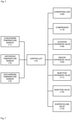
- FIG. 2 is a block diagram of the air condition according to an exemplary embodiment of the present invention.
- the air conditioner includes a controller 10 for controlling the air conditioner, a condensing temperature sensor 11 for measuring a condensing temperature of refrigerant, and a vaporizing temperature sensor 12 for measuring a vaporizing temperature of refrigerant, and a discharging temperature sensor 16 for measuring a discharging temperature of refrigerant discharged from the compressor 110.
- the controller 10 controls the operation of the air conditioner by controlling the converting unit 190, the compressor 110, the outdoor expansion valve 140, the indoor expansion valve 150, the injection expansion valve 171, the injection valve 173, and the supercooling valve 174.
- the controller 10 selects the cooling and heating operations by controlling the converting unit 190.
- the controller 10 controls the operating speed of the compressor 110 according to a load.
- the controller 10 adjusts the opening degree of the outdoor expansion valve 140 in the heating operation and opens the outdoor expansion valve 140 in the cooling operation.
- the controller 10 opens the indoor expansion valve 150 in the heating operation and adjusts the opening degree of the indoor expansion valve 150 in the cooling operation.
- the controller 10 adjusts the opening degree of the injection expansion valve 171 or closes the injection expansion valve.
- the controller 10 opens the supercooling valve 174 and closes the injection valve 173 in the cooling operation.
- the controller 10 opens the supercooling valve 174 in the cooling operation when the injection condition is satisfied and closes the same after a predetermined time passes, after which the controller 10 opens the injection valve 173.
- the operation of the supercooling valve 174 and the injection valve 173 in the heating operation will be described with reference to FIGS. 3 to 5 later.
- the condensing temperature sensor 11 measures the condensing temperature of refrigerant in the indoor heat exchanger 130 in the heating operation, and measures the condensing temperature of refrigerant in the outdoor heat exchanger 120 in the cooling operation.
- the condensing temperature sensor 11 is located at a variety of locations to measure the condensing temperature of refrigerant. In this exemplary embodiment, the condensing temperature sensor 11 is provided at a "d" location in the heating operation and at an "h" location in the cooling operation. In one embodiment, the condensing temperature sensor 11 may be provided on the indoor heat exchanger 130 in the heating operation, and may be provided on the outdoor heat exchanger 120 in the cooling operation.
- the condensing temperature of refrigerant may be calculated by measuring the pressure of refrigerant passing through the indoor heat exchanger 130 in the heating operation and may be calculated by measuring the pressure of refrigerant passing through the outdoor heat exchanger 120 in the cooling operation.
- the vaporizing temperature sensor 12 measures the vaporizing temperature of refrigerant in the outdoor heat exchanger 120 in the heating operation, and measures the vaporizing temperature of refrigerant in the indoor heat exchanger 130 in the cooling operation.
- the vaporizing temperature sensor 12 may measure the vaporizing temperature by being located at a variety of locations. In this exemplary embodiment, the vaporizing temperature sensor 12 is provided at an "i" location in the heating operation and at a "c" location in the cooling operation. In one embodiment, the vaporizing temperature sensor 12 is provided on the outdoor heat exchanger in the hating operation and at the indoor heat exchanger in the cooling operation.
- the vaporizing temperature of refrigerant may be calculated by measuring the pressure of refrigerant passing through the outdoor heat exchanger 120 in the heating operation and calculated by measuring the pressure of refrigerant passing through the indoor heat exchanger 130 in the cooling operation.
- the discharging temperature sensor 16 measures the discharging temperature ("b" location) of refrigerant compressed in the compressor 110 and discharged through the outlet port 114.
- the discharging temperature sensor 16 may be located at a variety of locations to measure the discharging temperature of refrigerant discharged from the compressor 110. In this exemplary embodiment, the discharging temperature sensor 16 is provided at a "b" location.
- FIG. 3 is a flowchart of a method for controlling an air conditioner according to an exemplary embodiment of the present invention
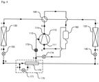
- FIGS. 4 and 5 are schematic views illustrating refrigerant flow in a heating operation of an air conditioner according to an exemplary embodiment of the present invention.
- the controller 10 starts the heating operation (S210).
- the controller 10 controls the converting unit 190 such that the outlet port 114 of the compressor 110 is connected to the indoor heat exchanger 130 and the outdoor heat exchanger 120 is connected to the accumulator 160.
- the controller 10 completely opens the outdoor expansion valve 140 and closes the injection expansion valve 171.
- the controller 10 controls the operating speed of the compressor 110 and the opening degree of the expansion valve 150.
- the controller 10 maintains the injection expansion valve 171 closed.
- the controller 10 closes the injection expansion valve 171.
- the controller 10 determines whether or not it is possible for the injection module 170 to inject (S220).
- the controller 10 determines whether or not the injection condition is satisfied and thus it is possible for the injection module 170 to inject refrigerant.
- the injection condition may be set based on the operating speed of the compressor 110, the discharge superheating degree, the condensing temperature, or the vaporizing temperature.
- the operating speed of the compressor 110 is an RPM of a motor (not shown) generating torque for compressing refrigerant.
- the operating speed of the compressor 110 may be represented in a frequency unit.
- the operating speed of the compressor 110 is proportional to a compression capacity of the compressor 110.
- the controller 10 may determine whether or not the injection condition is satisfied by determining whether or not the operating speed of the compressor is higher than a predetermined operating speed.
- the controller 10 may determine whether or not the injection condition is satisfied by determining whether or not the discharge superheating degree is higher than a predetermined discharge superheating degree.
- the condensing temperature is a condensing temperature of refrigerant measured by the condensing temperature sensor 11.
- the condensing temperature is a temperature at which refrigerant is condensed in the indoor heat exchanger 130.
- the controller 10 may determine whether or not the injection condition is satisfied by determining whether or not the condensing temperature satisfies a predetermined condition.
- the vaporizing temperature is a vaporizing temperature of refrigerant measured by the vaporizing temperature sensor 12.
- the vaporizing temperature is a temperature at which refrigerant is vaporized in the outdoor heat exchanger 120.
- the controller 10 may determine whether or not the injection condition is satisfied by determining whether or not the vaporizing temperature meets a predetermined condition.
- the condensing and vaporizing temperatures may have a condition having a linear inequality relationship.
- the injection condition in the heating operation may be set to meet one or at least two of the operating speed of the compressor 110, the discharge superheating degree, the condensing temperature, and the vaporizing temperature.
- the controller 10 opens the injection expansion valve 171 and the supercooling valve 174 and closes the injection valve 173 (S230).
- the controller 10 opens the injection expansion valve 171 that has been closed when starting the heating operation and adjusts the opening degree of the injection expansion valve 171 in accordance with the control logic.
- the controller 10 When the injection valve 173 is in a closed status in the start of the heating operation, the controller 10 maintains the injection valve 173 closed. When the injection valve 173 is in a closed status, the controller 10 closes the injection valve 173.
- the controller 10 When the supercooling valve 174 is in a closed status in the start of the heating operation, the controller 10 opens the supercooling valve 174. When the supercooling valve 174 is in an opened status, the controller 10 maintains the supercooling valve 174 opened.
- Refrigerant compressed in the compressor 110 is discharged through the outlet port 114 and directed to the converting unit 190.
- the converting unit 190 connects the outlet port 114 of the compressor 110 to the indoor heat exchanger 130. Therefore, refrigerant directed to the converting unit 190 is transferred to the indoor heat exchanger 130.
- Refrigerant transferred from the converting unit 190 to the indoor heat exchanger 130 heat-exchanges with the indoor air and is thus condensed.
- the condensed refrigerant is directed to the indoor expansion valve 150.
- refrigerant passes through the indoor expansion valve 150 and is then directed to the injection module 170.
- a portion of refrigerant coming from the indoor expansion valve 150 is directed to the injection expansion valve 171 and the rest is transferred to the injection heat exchanger 172.
- Refrigerant transferred to the injection expansion valve 171 expands and is directed to the injection heat exchanger 172.
- Refrigerant directed to the injection heat exchanger 172 is vaporized by heat-exchanging with refrigerant flowing to the injection heat-exchange 172.
- the injection valve 173 When the injection condition is satisfied, the injection valve 173 is closed and the supercooling valve 174 is open. Therefore, refrigerant vaporized in the injection heat exchanger 172 is directed to the accumulator 160 via the supercooling valve 174 and mixed with refrigerant vaporized in the indoor heat exchanger 130.
- a portion of refrigerant coming from the indoor expansion valve 150 is supercooled by heat-exchanging with refrigerant expanding by the injection expansion valve 171 in the injection heat exchanger 172.
- the supercooled refrigerant is directed to the outdoor expansion valve 140.
- Refrigerant directed to the outdoor expansion valve 140 expands and is then directed to the outdoor heat exchanger 120 and vaporized by heat-exchanging with the outdoor air.
- the vaporized refrigerant is transferred to the converting unit 190.
- the converting unit 190 connects, in the heating operation, the outdoor heat exchanger 120 to the accumulator 160. Therefore, refrigerant directed from the outdoor heat exchanger 120 to the converting unit 190 is transferred to the accumulator 160. Refrigerant transferred to the accumulator 160 is mixed with refrigerant coming from the supercooling valve 174 and the gas-phase and liquid-phase refrigerants are separated from the mixed refrigerant. The gas-phase refrigerant separated in the accumulator 160 is introduced into the compressor 110 through the inlet port 111 and compressed in the compressor 110, after which refrigerant is discharged through the outlet port 114.
- the controller 10 opens the supercooling valve 174 and maintains the injection valve 173 closed (S240).
- the controller 10 opens the supercooling valve 174 and maintains the injection valve 173 closed for a predetermined time so that the oil and condensed refrigerant remaining in the injection module 170 can be directed to the accumulator 160. That is, the predetermined time is a standby time for sufficiently discharging the oil and condensed refrigerant remaining in the injection module 170.
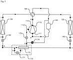
- the controller 10 closes the supercooling valve 174 after the predetermined time passes and opens the injection valve 173 (S250).
- Refrigerant compressed in the compressor 110 is directed to the converting unit 190.
- the converting unit 190 connects the outlet port 114 of the compressor 110 and the indoor heat exchanger 130. Therefore, refrigerant directed to the converting unit 190 is transferred to the indoor heat exchanger 130.
- Refrigerant directed from the converting unit 190 to the indoor heat exchanger 130 is condensed by heat-exchanging with the indoor air.
- the condensed refrigerant is transferred to the indoor expansion valve 150.
- the indoor expansion valve 150 is fully opened and thus refrigerant is directed to the injection module 170.
- a portion of refrigerant coming from the indoor expansion valve 150 is directed to the injection expansion valve 171 and the rest is again directed to the injection heat exchanger 172.
- Refrigerant directed to the injection expansion valve 171 expands and is then directed to the injection heat exchanger 172.
- Refrigerant expanding in the injection expansion valve 171 is transferred to the injection heat exchanger 172 and vaporized by heat-exchanging with refrigerant flowing from the indoor expansion valve 150 to the injection heat exchanger 172.
- the injection valve 173 is opened and the supercooling valve 174 is closed. Therefore, refrigerant vaporized in the injection heat exchanger 172 is transferred to the injection valve 173. Refrigerant passing through the injection valve 173 is directed to the compressor 110 through the injection port 112 and compressed by the compressor, after which refrigerant is discharged through the outlet port 114.
- a portion of refrigerant coming from the indoor expansion valve 150 is supercooled by heat-exchanging with refrigerant that expands by the injection expansion valve 171 in the injection heat exchanger 172.
- the supercooled refrigerant is directed to the outdoor expansion valve 140 and expands, after which it is directed to the outdoor heat exchanger 120.
- Refrigerant directed to the outdoor heat exchanger 120 is vaporized by heat-exchanging with the outdoor air.
- the vaporized refrigerant is transferred to the converting unit 190.
- the converting unit 190 connects the outdoor heat exchanger 120 to the accumulator 160 in the heating operation
- refrigerant directed from the outdoor heat exchanger 120 to the converting unit 190 is directed to the accumulator 160 and mixed with refrigerant directed from the supercooling valve 174, after which the gas-phase and liquid-phase refrigerants are separated from the mixed refrigerant.
- the gas-phase refrigerant separated in the accumulator 160 is introduced into the compressor 110 through the inlet port 111 and compressed by the compressor 110, after which it is discharged through the outlet port 114.
- only the vaporized refrigerant can be injected by opening the supercooling valve disposed between the injection module and the accumulator, closing the supercooling valve after a predetermined time passes, and opening the injection valve disposed between the injection module and the inlet port of the compressor.
Description
- The present disclosure relates to a method for controlling an air
- Generally, an air conditioner is a system that keeps air cool and warm using a refrigeration cycle including an outdoor heat exchanger, an expansion valve, and an indoor heat exchanger. That is, the air conditioner may be designed to have a cooling device for keeping indoor air cool and a heating device for keeping indoor air warm. Alternatively, the air conditioner may be designed to have a device with both cooling and heating functions.
- When the air conditioner is designed to have the device with both the cooling and heating functions, the air conditioner includes a converting unit for converting a flow passage of refrigerant compressed by a compressor in accordance with an operational condition (i.e., a cooling operation and a heating operation). That is, in the cooling operation, refrigerant compressed by the compressor is directed to the outdoor heat exchanger through the converting unit. At this point, the outdoor heat exchanger functions as a condenser. Refrigerant condensed by the outdoor heat exchanger expands in an expansion valve and is introduced into the indoor heat exchanger. At this point, the indoor heat exchanger functions as a vaporizer. Refrigerant vaporized by the indoor heat exchanger is redirected into the compressor through the converting unit.
- The air conditioner improves its efficiency by injecting a portion of refrigerant condensed in the heating or cooling operation into the compressor.
-
JP 2008 138921 (A claim 1. -
WO 2012/098582 (A1 ) relates to a refrigeration cycle apparatus including means for physically cleaning a foreign substance with a refrigerant. - Thus, an object of the present invention is to provide a method for controlling an air conditioner to stably inject refrigerant to a compressor. According to the present invention, there is provided a method as defined by
claim 1. - The accompanying drawings, which are included to provide a further understanding of the invention and are incorporated in and constitute a part of this specification, illustrate embodiments of the invention and together with the description serve to explain the principles of the invention.
- In the drawings:
FIG. 1 is a schematic view illustrating a refrigerant flow in a cooling operation of an air conditioner according to an exemplary embodiment of the present invention:
FIG. 2 is a block diagram of an air conditioner according to an exemplary embodiment of the present invention: -
FIG. 3 is a flowchart of a method for controlling an air conditioner according to an exemplary embodiment of the present invention: and -
FIGS. 4 and5 are schematic views illustrating a refrigerant flow in a heating operation of an air conditioner according to an exemplary embodiment of the present invention. - The foregoing and other objects, features, aspects and advantages of the present invention will become more apparent from the following detailed description of the present invention when taken in conjunction with the accompanying drawings. Exemplary embodiments of the present invention will now be described in detail with reference to the accompanying drawings. The invention may, however, be embodied in many different forms and should not be construed as being limited to the embodiments set forth herein. Rather, these embodiments are provided so that this disclosure will be thorough and complete, and will fully convey the scope of the invention to those skilled in the art. In the drawings, the shapes and dimensions may be exaggerated for clarity, and the same reference numerals will be used throughout to designate the same or like components.
- Hereinafter, exemplary embodiments of the present invention will be described in detail with reference to the accompanying drawings.
-
FIG. 1 is a schematic view illustrating a refrigerant flow in a cooling operation of an air conditioner according to an exemplary embodiment of the present invention. - An air conditioner of an exemplary embodiment of the present invention includes a
compressor 110 for compressing refrigerant, anoutdoor heat exchanger 120 that is installed out of a room for heat-exchange between outdoor air and refrigerant, anindoor heat exchanger 130 that is installed in the room for heat-exchange between indoor air and refrigerant, a convertingunit 190 for directing refrigerant from thecompressor 110 to theoutdoor heat exchanger 120 in an cooling operation and directing refrigerant from thecompressor 110 to the indoor heat exchanger in a heating operation, aninjection module 170 for expanding and vaporizing a portion of refrigerant flowing from theoutdoor heat exchanger 120 to theindoor heat exchanger 130, asupercooling valve 174 for directing, when it is open, refrigerant vaporized by theinjection module 170 to anaccumulator 160, and aninjection valve 173 for, when it is open, injecting refrigerant vaporized by theinjection module 170 to thecompressor 110. - The
compressor 110 compresses refrigerant introduced from a low-pressure low-temperature state to a high-pressure high-temperature state. Thecompressor 110 may be formed in a variety of structures. That is, thecompressor 110 may be a reciprocating compressor using a cylinder and a piston or a scroll compressor using an orbiting scroll and a fixed scroll. In this exemplary embodiment, thecompressor 110 is the scroll compressor. In one embodiment, a plurality of compressors may be provided. - The
compressor 110 includes aninlet port 111 through which refrigerant vaporized in theindoor heat exchanger 130 is introduced in the cooling operation or refrigerant vaporized in theoutdoor heat exchanger 120 is introduced in the heating operation, aninjection port 112 through which refrigerant that expands and is vaporized in theinjection module 170 is introduced, and anoutlet port 114 through which the compressed refrigerant is discharged. - Refrigerant introduced through the
inlet port 111 has pressure and temperature that are lower than those of refrigerant introduced through theinjection port 112. Refrigerant introduced into theinjection port 112 has pressure and temperature that are lower than those of refrigerant discharged through theoutlet port 114. - The
compressor 110 compresses refrigerant introduced through theinlet port 111 in a compressing chamber. Refrigerant introduced through theinlet port 111 and refrigerant introduced through theinjection port 112 are mixed with each other and compressed by thecompressor 110, after which it is discharged through theoutlet port 114. - The
accumulator 160 separates a gas-phase refrigerant and a liquid-phase refrigerant from refrigerant vaporized in theindoor heat exchanger 130 in the cooling operation or refrigerant vaporized in theoutdoor heat exchanger 120 in the heating operation. Theaccumulator 160 is provided between the convertingunit 190 and theinlet port 111 of thecompressor 110. The gas-phase refrigerant separated in theaccumulator 160 is introduced into thecompressor 110 through theinlet port 111. - The converting
unit 190 is a flow passage converting valve for cooling-heating conversion. The convertingunit 190 directs refrigerant compressed in thecompressor 110 to theoutdoor heat exchanger 120 in the cooling operation and to theindoor heat exchanger 130 in the heating operation. In one embodiment, the convertingunit 190 may be formed of a variety of valves or a combination thereof that can convert four flow passages. - The converting
unit 190 is connected to theoutlet port 114 of thecompressor 110 and theaccumulator 160 and is further connected to the indoor andoutdoor heat exchangers unit 190 connects theoutlet port 114 of thecompressor 110 to theoutdoor heat exchanger 120 and further connects theindoor heat exchanger 130 to theaccumulator 160. In the heating operation, the convertingunit 190 connects theoutlet port 114 of thecompressor 110 to theindoor heat exchanger 130 and further connects theoutdoor heat exchanger 120 to theaccumulator 160. - The converting
unit 190 may be formed in a variety of different modules that can connect different passages to each other. In this exemplary embodiment, a four-way valve may be used for the convertingunit 190. However, the present invention is not limited to this exemplary embodiment. A combination of two 3-way valves or other valves may be used as the converting unit. - The
outdoor heat exchanger 120 may be disposed out of the room. Refrigerant heat-exchanges with the outdoor air while passing through theoutdoor heat exchanger 120. Theoutdoor heat exchanger 120 functions as a condenser for condensing refrigerant in the cooling operation and as a vaporizer for vaporizing refrigerant in the heating operation. - The
outdoor heat exchanger 120 is connected to the convertingunit 190 and theoutdoor expansion valve 140. In the cooling operation, refrigerant compressed in thecompressor 110 and passing through theoutlet port 114 of thecompressor 110 and the convertingunit 190 is introduced into theoutdoor heat exchanger 120 and condensed, after which refrigerant is directed to theoutdoor expansion valve 140. In the heating operation, refrigerant expanding in theoutdoor expansion valve 140 is introduced into theindoor heat exchanger 120 and vaporized and discharged to the convertingunit 190. - The
outdoor expansion valve 140 is completely opened in the cooling operation to allow refrigerant to pass. In the heating operation, the opening degree of theindoor expansion valve 140 is adjusted to expand refrigerant. Theoutdoor expansion valve 140 is connected to theoutdoor heat exchanger 120 and theinjection module 170. Theoutdoor expansion valve 140 is provided between theoutdoor heat exchanger 120 and theinjection module 170. - The
outdoor expansion valve 140 directs refrigerant introduced from theoutdoor heat exchanger 120 to theinjection module 170 in the cooling operation. Theoutdoor expansion valve 140 expands refrigerant flowing from theinjection module 170 to theoutdoor heat exchanger 120 in the heating operation. - The
indoor heat exchanger 130 is disposed in the room to allow refrigerant passing through theindoor heat exchanger 130 to heat-exchange with the indoor air. In the cooling operation, theindoor heat exchanger 130 functions as a vaporizer for vaporizing refrigerant. In the heating operation, theindoor heat exchanger 130 functions as a condenser for condensing refrigerant. - The
indoor heat exchanger 130 is connected to the convertingunit 190 and theindoor expansion valve 150. In the cooling operation, refrigerant expanding in theindoor expansion valve 150 is directed into theindoor heat exchanger 130 and vaporized and discharged to the convertingunit 190. In the heating operation, refrigerant that is compressed in thecompressor 110 and passes through theoutlet port 114 of thecompressor 110 and the convertingunit 190 is introduced into theheat exchanger 130 and condensed and directed to theindoor expansion valve 150. - In the cooling operation, the opening degree of the
indoor expansion valve 150 is adjusted to expand refrigerant. In the heating operation, theindoor expansion valve 150 is completely opened to allow refrigerant to pass therethrough. Theindoor expansion valve 150 is connected to theindoor heat exchanger 130 and theinjection module 170 and disposed between theindoor heat exchanger 130 and theinjection module 170. - In the cooling operation, the
indoor expansion valve 150 expands refrigerant flowing from theinjection module 170 to theindoor heat exchanger 130. In the heating operation, theindoor expansion valve 150 directs refrigerant from theindoor heat exchanger 130 to theinjection module 170. - In the cooling operation, the
injection module 170 supercools refrigerant. In the heating operation, theinjection module 170 supercools refrigerant or injects a portion of refrigerant to thecompressor 110. In one embodiment, the injection module 1'70 may inject a portion of refrigerant to thecompressor 110 in the cooling operation. Theinjection module 170 is connected to theindoor expansion valve 150, theinjection valve 173, the supercoolingvalve 174, and theoutdoor expansion valve 140. - In the cooling operation, the
injection module 170 expands and vaporizes a portion of refrigerant coming from theoutdoor heat exchanger 120. In addition, theinjection module 170 supercools refrigerant coming from theoutdoor heat exchanger 120 and directs refrigerant to theindoor expansion valve 150. - In the heating operation, the
injection module 170 expands and vaporizes a portion of refrigerant coming from theindoor heat exchanger 130. In addition, theinjection module 170 supercools the rest of refrigerant coming from theindoor heat exchanger 130 and directs refrigerant to theoutdoor expansion valve 140. - The
injection module 170 includes aninjection expansion valve 171 for expanding a portion of refrigerant passing therethrough and aninjection heat exchanger 172 supercools the rest of refrigerant passing therethrough by heat-exchanging with refrigerant expanding in theinjection expansion valve 171. - The
injection expansion valve 171 is connected to theindoor expansion valve 150 and theinjection heat exchanger 172. Theinjection expansion valve 171 expands refrigerant flowing from the second injection heat exchanger 182 to theaccumulator 160 in the cooling operation. Theinjection expansion valve 171 expands refrigerant injected from theindoor heat exchanger 130 to theaccumulator 160 or thecompressor 110 in the heating operation. - In the cooling operation, the
injection expansion valve 171 expands a portion of refrigerant that passes through theinjection heat exchanger 172 via theoutdoor heat exchanger 120 and theoutdoor expansion valve 140 and directs the expanding refrigerant to theinjection heat exchanger 172. In the heating operation, theinjection expansion valve 171 expands a portion of refrigerant coming from theindoor heat exchanger 130 via theindoor expansion valve 150 and directs the same to theinjection heat exchanger 172. - The
injection heat exchanger 172 is connected to theindoor expansion valve 150, theinjection expansion valve 171, theoutdoor expansion valve 150, theinjection valve 173, and thesupercooling valve 174. - In the cooling operation, the
injection heat exchanger 172 allows refrigerant, which comes from theoutdoor heat exchanger 120 via theoutdoor expansion valve 140, to heat-exchange with refrigerant expanding in theinjection expansion valve 171. In the heating operation, theinjection heat exchanger 172 allows refrigerant, which comes from theindoor heat exchanger 130 via theindoor expansion valve 150, to heat-exchange with refrigerant expanding in theinjection expansion valve 171. - In the cooling operation, the
injection heat exchanger 172 allows refrigerant coming from theoutdoor heat exchanger 120 to heat-exchange with refrigerant expanding in theinjection expansion valve 171. In the cooling operation, refrigerant supercooled in theinjection heat exchanger 172 is directed to theindoor expansion valve 150 and vaporized and further directed to theaccumulator 160 via thesupercooling valve 174. - In the heating operation, the
injection heat exchanger 172 allows a portion of refrigerant coming from theindoor heat exchanger 130 to heat-exchange with refrigerant expanding in theinjection expansion valve 171. In the heating operation, refrigerant supercooled in theinjection heat exchanger 172 is directed to theoutdoor expansion valve 140 and vaporized and directed to theaccumulator 160 via thesupercooling valve 174 or injected to theinjection port 112 of thecompressor 110 via theinjection valve 173. - The supercooling
valve 174 is disposed between theinjection heat exchanger 172 of theinjection module 170 and theaccumulator 160. In the cooling operation, the supercoolingvalve 174 is opened and directs refrigerant expanding in theinjection expansion valve 171 and vaporized in theinjection heat exchanger 172 to theaccumulator 160. Refrigerant directed to theaccumulator 160 is mixed with refrigerant heat-exchanging in theindoor heat exchanger 130. In the heating operation, the supercoolingvalve 174 is opened when the injection condition is satisfied so as to direct refrigerant vaporized in theinjection heat exchanger 172 to theaccumulator 160 and is then closed after a predetermined time passed. - The
injection valve 173 is disposed between theinjection heat exchanger 172 of theinjection module 170 and theinjection port 112 of thecompressor 110. In the cooling operation, theinjection valve 173 is closed. Theinjection valve 173, in the heating operation, is opened when thesupercooling valve 174 is closed so as to direct refrigerant expanding in theinjection expansion valve 171 and vaporized in theinjection heat exchanger 172 to theinjection port 112 of thecompressor 110. - The operation of the
supercooling valve 174 and theinjection valve 173 in the heating operation will be described with reference toFIGS. 3 to 5 later. - Hereinafter, a cooling operation of an air condition according to an exemplary embodiment of the present invention will be described.
- Refrigerant compressed in the
compressor 110 is discharged through theoutlet port 114 and directed to the convertingunit 190. In the cooling operation, the convertingunit 190 connects theoutlet port 114 of thecompressor 110 to theoutdoor heat exchanger 120 and thus refrigerant directed to the convertingunit 190 is directed to theoutdoor heat exchanger 120. - Refrigerant directed from the converting
unit 190 to theoutdoor heat exchanger 120 heat-exchanges with the outdoor air and thus is condensed. Refrigerant condensed in theoutdoor heat exchanger 120 is transferred to theoutdoor expansion valve 140. In the cooling operation, theoutdoor expansion valve 140 is fully opened and thus refrigerant passes through theoutdoor expansion valve 140 and is then directed to theinjection module 170. - Refrigerant transferred to the
injection module 170 is supercooled in theinjection heat exchanger 172. A portion of refrigerant supercooled in theinjection heat exchanger 172 is directed to theinjection expansion valve 171. Refrigerant expanding in theinjection expansion valve 171 heat-exchanges with refrigerant flowing from theinjection heat exchanger 172 to theoutdoor heat exchanger 120 and is vaporized. - In the cooling operation, the
injection valve 173 is closed and thesupercooling valve 174 is open. Therefore, refrigerant vaporized in theinjection heat exchanger 172 is transferred to thesupercooling valve 174. Refrigerant passing through thesupercooling valve 174 is directed to theaccumulator 160 and mixed with refrigerant vaporized in theindoor heat exchanger 130 - A portion of refrigerant supercooled in the
injection heat exchanger 172 is directed to theindoor expansion valve 150. Refrigerant expanding in theindoor expansion valve 150 is transferred to theindoor heat exchanger 130. Refrigerant directed to theindoor heat exchanger 130 is vaporized by heat-exchanging with the indoor air. The vaporized refrigerant is transferred to the convertingunit 190. - Since the converting
unit 190 connects theindoor heat exchanger 130 to theaccumulator 160 in the cooling operation, refrigerant directed from theindoor heat exchanger 130 to the convertingunit 190 is transferred to theaccumulator 160. Refrigerant transferred to theaccumulator 160 is mixed with refrigerant coming from the supercoolingvalve 174. The gas-phase and liquid-phase refrigerants are separated from the mixed refrigerant. The gas-phase refrigerant separated in theaccumulator 160 is introduced into thecompressor 110 through theinlet port 111 and compressed and discharged through theoutlet port 111. -
FIG. 2 is a block diagram of the air condition according to an exemplary embodiment of the present invention. - Referring to
FIG. 2 , the air conditioner according to an exemplary embodiment of the present invention includes acontroller 10 for controlling the air conditioner, a condensingtemperature sensor 11 for measuring a condensing temperature of refrigerant, and a vaporizingtemperature sensor 12 for measuring a vaporizing temperature of refrigerant, and a discharging temperature sensor 16 for measuring a discharging temperature of refrigerant discharged from thecompressor 110. - The
controller 10 controls the operation of the air conditioner by controlling the convertingunit 190, thecompressor 110, theoutdoor expansion valve 140, theindoor expansion valve 150, theinjection expansion valve 171, theinjection valve 173, and thesupercooling valve 174. - The
controller 10 selects the cooling and heating operations by controlling the convertingunit 190. Thecontroller 10 controls the operating speed of thecompressor 110 according to a load. Thecontroller 10 adjusts the opening degree of theoutdoor expansion valve 140 in the heating operation and opens theoutdoor expansion valve 140 in the cooling operation. Thecontroller 10 opens theindoor expansion valve 150 in the heating operation and adjusts the opening degree of theindoor expansion valve 150 in the cooling operation. Thecontroller 10 adjusts the opening degree of theinjection expansion valve 171 or closes the injection expansion valve. - The
controller 10 opens thesupercooling valve 174 and closes theinjection valve 173 in the cooling operation. Thecontroller 10 opens thesupercooling valve 174 in the cooling operation when the injection condition is satisfied and closes the same after a predetermined time passes, after which thecontroller 10 opens theinjection valve 173. The operation of thesupercooling valve 174 and theinjection valve 173 in the heating operation will be described with reference toFIGS. 3 to 5 later. - The condensing
temperature sensor 11 measures the condensing temperature of refrigerant in theindoor heat exchanger 130 in the heating operation, and measures the condensing temperature of refrigerant in theoutdoor heat exchanger 120 in the cooling operation. The condensingtemperature sensor 11 is located at a variety of locations to measure the condensing temperature of refrigerant. In this exemplary embodiment, the condensingtemperature sensor 11 is provided at a "d" location in the heating operation and at an "h" location in the cooling operation. In one embodiment, the condensingtemperature sensor 11 may be provided on theindoor heat exchanger 130 in the heating operation, and may be provided on theoutdoor heat exchanger 120 in the cooling operation. - In one embodiment, the condensing temperature of refrigerant may be calculated by measuring the pressure of refrigerant passing through the
indoor heat exchanger 130 in the heating operation and may be calculated by measuring the pressure of refrigerant passing through theoutdoor heat exchanger 120 in the cooling operation. - The vaporizing
temperature sensor 12 measures the vaporizing temperature of refrigerant in theoutdoor heat exchanger 120 in the heating operation, and measures the vaporizing temperature of refrigerant in theindoor heat exchanger 130 in the cooling operation. The vaporizingtemperature sensor 12 may measure the vaporizing temperature by being located at a variety of locations. In this exemplary embodiment, the vaporizingtemperature sensor 12 is provided at an "i" location in the heating operation and at a "c" location in the cooling operation. In one embodiment, the vaporizingtemperature sensor 12 is provided on the outdoor heat exchanger in the hating operation and at the indoor heat exchanger in the cooling operation. - In one embodiment, the vaporizing temperature of refrigerant may be calculated by measuring the pressure of refrigerant passing through the
outdoor heat exchanger 120 in the heating operation and calculated by measuring the pressure of refrigerant passing through theindoor heat exchanger 130 in the cooling operation. - The discharging temperature sensor 16 measures the discharging temperature ("b" location) of refrigerant compressed in the
compressor 110 and discharged through theoutlet port 114. The discharging temperature sensor 16 may be located at a variety of locations to measure the discharging temperature of refrigerant discharged from thecompressor 110. In this exemplary embodiment, the discharging temperature sensor 16 is provided at a "b" location. -
FIG. 3 is a flowchart of a method for controlling an air conditioner according to an exemplary embodiment of the present invention, andFIGS. 4 and5 are schematic views illustrating refrigerant flow in a heating operation of an air conditioner according to an exemplary embodiment of the present invention. - The
controller 10 starts the heating operation (S210). Thecontroller 10 controls the convertingunit 190 such that theoutlet port 114 of thecompressor 110 is connected to theindoor heat exchanger 130 and theoutdoor heat exchanger 120 is connected to theaccumulator 160. In addition, thecontroller 10 completely opens theoutdoor expansion valve 140 and closes theinjection expansion valve 171. Further, in accordance with the heating operation control logic, thecontroller 10 controls the operating speed of thecompressor 110 and the opening degree of theexpansion valve 150. - In addition, when the
injection expansion valve 171 is in a closed status, thecontroller 10 maintains theinjection expansion valve 171 closed. When theinjection expansion valve 171 is in an opened status, thecontroller 10 closes theinjection expansion valve 171. - The
controller 10 determines whether or not it is possible for theinjection module 170 to inject (S220). Thecontroller 10 determines whether or not the injection condition is satisfied and thus it is possible for theinjection module 170 to inject refrigerant. The injection condition may be set based on the operating speed of thecompressor 110, the discharge superheating degree, the condensing temperature, or the vaporizing temperature. - The operating speed of the
compressor 110 is an RPM of a motor (not shown) generating torque for compressing refrigerant. The operating speed of thecompressor 110 may be represented in a frequency unit. The operating speed of thecompressor 110 is proportional to a compression capacity of thecompressor 110. Thecontroller 10 may determine whether or not the injection condition is satisfied by determining whether or not the operating speed of the compressor is higher than a predetermined operating speed. - The discharge superheating degree is a difference between the discharging temperature measured by the discharging temperature sensor 16 and the condensing temperature measured by the condensing
temperature sensor 11. That is, (Discharge Superheating Degree) = (Discharging Temperature) - (Condensing Temperature). Thecontroller 10 may determine whether or not the injection condition is satisfied by determining whether or not the discharge superheating degree is higher than a predetermined discharge superheating degree. - The condensing temperature is a condensing temperature of refrigerant measured by the condensing
temperature sensor 11. In the heating operation, the condensing temperature is a temperature at which refrigerant is condensed in theindoor heat exchanger 130. Thecontroller 10 may determine whether or not the injection condition is satisfied by determining whether or not the condensing temperature satisfies a predetermined condition. - The vaporizing temperature is a vaporizing temperature of refrigerant measured by the vaporizing
temperature sensor 12. In the heating operation, the vaporizing temperature is a temperature at which refrigerant is vaporized in theoutdoor heat exchanger 120. Thecontroller 10 may determine whether or not the injection condition is satisfied by determining whether or not the vaporizing temperature meets a predetermined condition. The condensing and vaporizing temperatures may have a condition having a linear inequality relationship. - In one embodiment, the injection condition in the heating operation may be set to meet one or at least two of the operating speed of the
compressor 110, the discharge superheating degree, the condensing temperature, and the vaporizing temperature. - When the injection condition is satisfied, the
controller 10 opens theinjection expansion valve 171 and thesupercooling valve 174 and closes the injection valve 173 (S230). Thecontroller 10 opens theinjection expansion valve 171 that has been closed when starting the heating operation and adjusts the opening degree of theinjection expansion valve 171 in accordance with the control logic. - When the
injection valve 173 is in a closed status in the start of the heating operation, thecontroller 10 maintains theinjection valve 173 closed. When theinjection valve 173 is in a closed status, thecontroller 10 closes theinjection valve 173. - When the
supercooling valve 174 is in a closed status in the start of the heating operation, thecontroller 10 opens thesupercooling valve 174. When thesupercooling valve 174 is in an opened status, thecontroller 10 maintains thesupercooling valve 174 opened. - The operation of the air condition when the injection condition is satisfied in the heating operation will be described hereinafter with reference to
FIG. 4 . - Refrigerant compressed in the
compressor 110 is discharged through theoutlet port 114 and directed to the convertingunit 190. In the heating operation, the convertingunit 190 connects theoutlet port 114 of thecompressor 110 to theindoor heat exchanger 130. Therefore, refrigerant directed to the convertingunit 190 is transferred to theindoor heat exchanger 130. - Refrigerant transferred from the converting
unit 190 to theindoor heat exchanger 130 heat-exchanges with the indoor air and is thus condensed. The condensed refrigerant is directed to theindoor expansion valve 150. In the heating operation, since theindoor expansion valve 150 is completely open, refrigerant passes through theindoor expansion valve 150 and is then directed to theinjection module 170. - A portion of refrigerant coming from the
indoor expansion valve 150 is directed to theinjection expansion valve 171 and the rest is transferred to theinjection heat exchanger 172. - Refrigerant transferred to the
injection expansion valve 171 expands and is directed to theinjection heat exchanger 172. Refrigerant directed to theinjection heat exchanger 172 is vaporized by heat-exchanging with refrigerant flowing to the injection heat-exchange 172. - When the injection condition is satisfied, the
injection valve 173 is closed and thesupercooling valve 174 is open. Therefore, refrigerant vaporized in theinjection heat exchanger 172 is directed to theaccumulator 160 via thesupercooling valve 174 and mixed with refrigerant vaporized in theindoor heat exchanger 130. - A portion of refrigerant coming from the
indoor expansion valve 150 is supercooled by heat-exchanging with refrigerant expanding by theinjection expansion valve 171 in theinjection heat exchanger 172. The supercooled refrigerant is directed to theoutdoor expansion valve 140. Refrigerant directed to theoutdoor expansion valve 140 expands and is then directed to theoutdoor heat exchanger 120 and vaporized by heat-exchanging with the outdoor air. The vaporized refrigerant is transferred to the convertingunit 190. - The converting
unit 190 connects, in the heating operation, theoutdoor heat exchanger 120 to theaccumulator 160. Therefore, refrigerant directed from theoutdoor heat exchanger 120 to the convertingunit 190 is transferred to theaccumulator 160. Refrigerant transferred to theaccumulator 160 is mixed with refrigerant coming from the supercoolingvalve 174 and the gas-phase and liquid-phase refrigerants are separated from the mixed refrigerant. The gas-phase refrigerant separated in theaccumulator 160 is introduced into thecompressor 110 through theinlet port 111 and compressed in thecompressor 110, after which refrigerant is discharged through theoutlet port 114. - The
controller 10 opens thesupercooling valve 174 and maintains theinjection valve 173 closed (S240). Thecontroller 10 opens thesupercooling valve 174 and maintains theinjection valve 173 closed for a predetermined time so that the oil and condensed refrigerant remaining in theinjection module 170 can be directed to theaccumulator 160. That is, the predetermined time is a standby time for sufficiently discharging the oil and condensed refrigerant remaining in theinjection module 170. - The
controller 10 closes thesupercooling valve 174 after the predetermined time passes and opens the injection valve 173 (S250). - The operation of the air conditioner when the injection condition is satisfied and the predetermined time passes will be described hereinafter with reference to
FIG. 5 . - Refrigerant compressed in the
compressor 110 is directed to the convertingunit 190. In the heating operation, the convertingunit 190 connects theoutlet port 114 of thecompressor 110 and theindoor heat exchanger 130. Therefore, refrigerant directed to the convertingunit 190 is transferred to theindoor heat exchanger 130. - Refrigerant directed from the converting
unit 190 to theindoor heat exchanger 130 is condensed by heat-exchanging with the indoor air. The condensed refrigerant is transferred to theindoor expansion valve 150. In the heating operation, theindoor expansion valve 150 is fully opened and thus refrigerant is directed to theinjection module 170. - A portion of refrigerant coming from the
indoor expansion valve 150 is directed to theinjection expansion valve 171 and the rest is again directed to theinjection heat exchanger 172. - Refrigerant directed to the
injection expansion valve 171 expands and is then directed to theinjection heat exchanger 172. Refrigerant expanding in theinjection expansion valve 171 is transferred to theinjection heat exchanger 172 and vaporized by heat-exchanging with refrigerant flowing from theindoor expansion valve 150 to theinjection heat exchanger 172. - After a predetermined time passes, the
injection valve 173 is opened and thesupercooling valve 174 is closed. Therefore, refrigerant vaporized in theinjection heat exchanger 172 is transferred to theinjection valve 173. Refrigerant passing through theinjection valve 173 is directed to thecompressor 110 through theinjection port 112 and compressed by the compressor, after which refrigerant is discharged through theoutlet port 114. - A portion of refrigerant coming from the
indoor expansion valve 150 is supercooled by heat-exchanging with refrigerant that expands by theinjection expansion valve 171 in theinjection heat exchanger 172. The supercooled refrigerant is directed to theoutdoor expansion valve 140 and expands, after which it is directed to theoutdoor heat exchanger 120. Refrigerant directed to theoutdoor heat exchanger 120 is vaporized by heat-exchanging with the outdoor air. The vaporized refrigerant is transferred to the convertingunit 190. - Since the converting
unit 190 connects theoutdoor heat exchanger 120 to theaccumulator 160 in the heating operation, refrigerant directed from theoutdoor heat exchanger 120 to the convertingunit 190 is directed to theaccumulator 160 and mixed with refrigerant directed from the supercoolingvalve 174, after which the gas-phase and liquid-phase refrigerants are separated from the mixed refrigerant. The gas-phase refrigerant separated in theaccumulator 160 is introduced into thecompressor 110 through theinlet port 111 and compressed by thecompressor 110, after which it is discharged through theoutlet port 114. - According to the air conditioner and the method for controlling the air conditioner of the present invention has at least one of the following effects.
- First, since the oil and condensed refrigerant remaining in the injection module in the initial stage of the heating operation are not injected into the compressor, the reliability of the compressor can be improved.
- Second, in the initial stage of the heating operation, only the vaporized refrigerant can be injected by opening the supercooling valve disposed between the injection module and the accumulator, closing the supercooling valve after a predetermined time passes, and opening the injection valve disposed between the injection module and the inlet port of the compressor.
- The effects of the present invention are not limited to the above; other effects that are not described herein will be clearly understood by the persons skilled in the art from the following claim.
Claims (1)
- A method of controlling an air conditioner wherein the air conditioner comprises:a compressor (110) for compressing refrigerant;an outdoor heat exchanger (120) disposed outdoors for allowing refrigerant to heat-exchange with outdoor air;an indoor heat exchanger (130) disposed indoors for allowing refrigerant to heat-exchange with indoor air;a converting unit (190) for directing refrigerant discharged from the compressor (110) to the outdoor heat exchanger (120) in a cooling operation and to the indoor heat exchanger (130) in a heating operation;an accumulator (160) disposed between the converting unit (190) and the compressor (110) for separating gas-phase and liquid phase refrigerants;an injection module (170) for expanding and vaporizing a portion of refrigerant flowing from the outdoor heat exchanger (120) in the cooling operation and for expanding and vaporizing a portion of refrigerant flowing from the indoor heat exchanger (130) in the heating operation;wherein the injection module (170) comprises:an injection expansion valve (171) for expanding a portion of refrigerant flowing therethrough; andan injection heat exchanger (172) for supercooling the rest of refrigerant by allowing refrigerant to heat-exchange with refrigerant expanding in the injection expansion valve (171),a supercooling valve (174) disposed between the injection module (170) and the accumulator (160) and adapted to be opened to direct refrigerant vaporized in the injection module (170) to the accumulator (160);an injection valve (173) disposed between the injection module (170) and the compressor (110) and adapted to be opened to inject refrigerant vaporized in the injection module (170) to the compressor (110); anda controller (10) for controlling the converting unit (190), the compressor (110), the injection expansion valve (171), the injection valve (173) and the supercooling valve (174);the method comprising:directing, by the converting unit (190) controlled by the controller, refrigerant discharged from the compressor (110) to the indoor heat exchanger (130) to start the heating operation, wherein the injection expansion valve (171), the supercooling valve (174) and the injection valve (173) are closed by the controller (10); characterised indirecting oil and condensed refrigerant remaining and vaporized in the injection module (170) to the accumulator (160) for a predetermined time by the controller (10) opening the supercooling valve (174) and the injection expansion valve (171) when the controller determines that at least one of a discharge superheating degree that is a difference between a discharging temperature of refrigerant of the compressor (110) and a condensing temperature of refrigerant in the indoor heat exchanger (130) and an operating speed of the compressor (110) satisfies a predetermined condition; andinjecting refrigerant vaporized in the injection module (170) to the compressor (110) by the controller (10) closing the supercooling valve (174) after the predetermined time passes and opening the injection valve (173) after the predetermined time passes.
Applications Claiming Priority (1)
| Application Number | Priority Date | Filing Date | Title |
|---|---|---|---|
| KR1020130041157A KR102163859B1 (en) | 2013-04-15 | 2013-04-15 | Air Conditioner and Controlling method for the same |
Publications (2)
| Publication Number | Publication Date |
|---|---|
| EP2792973A1 EP2792973A1 (en) | 2014-10-22 |
| EP2792973B1 true EP2792973B1 (en) | 2022-01-19 |
Family
ID=50478326
Family Applications (1)
| Application Number | Title | Priority Date | Filing Date |
|---|---|---|---|
| EP14164543.2A Active EP2792973B1 (en) | 2013-04-15 | 2014-04-14 | Method for controlling an air conditioner |
Country Status (4)
| Country | Link |
|---|---|
| US (1) | US9618237B2 (en) |
| EP (1) | EP2792973B1 (en) |
| KR (1) | KR102163859B1 (en) |
| CN (1) | CN104110919A (en) |
Families Citing this family (13)
| Publication number | Priority date | Publication date | Assignee | Title |
|---|---|---|---|---|
| US9976785B2 (en) | 2014-05-15 | 2018-05-22 | Lennox Industries Inc. | Liquid line charge compensator |
| US10330358B2 (en) * | 2014-05-15 | 2019-06-25 | Lennox Industries Inc. | System for refrigerant pressure relief in HVAC systems |
| SE539671C2 (en) * | 2014-12-23 | 2017-10-31 | Fläkt Woods AB | Apparatus and method for heating air in an air treatment device. |
| CN104879974A (en) * | 2015-05-11 | 2015-09-02 | 广东美的暖通设备有限公司 | Refrigeration system for air conditioner, method and apparatus for controlling defrosting, and air conditioner |
| US10260780B2 (en) | 2015-10-27 | 2019-04-16 | Gd Midea Heating & Ventilating Equipment Co., Ltd. | Enhanced vapor injection air conditioning system |
| CN105650919B (en) * | 2016-02-02 | 2018-11-30 | 珠海格力电器股份有限公司 | Air-conditioning system and jet degree of superheat adjusting method |
| JP2017146061A (en) * | 2016-02-19 | 2017-08-24 | 三星電子株式会社Samsung Electronics Co.,Ltd. | Air conditioner |
| US10866018B2 (en) | 2016-02-19 | 2020-12-15 | Samsung Electronics Co., Ltd. | Air conditioner and control method thereof |
| CN107356012A (en) * | 2016-05-09 | 2017-11-17 | 开利公司 | Heat pump and its control method |
| JP6319388B2 (en) * | 2016-09-12 | 2018-05-09 | ダイキン工業株式会社 | Refrigeration equipment |
| US10663199B2 (en) | 2018-04-19 | 2020-05-26 | Lennox Industries Inc. | Method and apparatus for common manifold charge compensator |
| US10830514B2 (en) | 2018-06-21 | 2020-11-10 | Lennox Industries Inc. | Method and apparatus for charge compensator reheat valve |
| CN109386985B (en) * | 2018-10-22 | 2020-07-28 | 广东美的暖通设备有限公司 | Two-pipe jet enthalpy-increasing outdoor unit and multi-split system |
Family Cites Families (30)
| Publication number | Priority date | Publication date | Assignee | Title |
|---|---|---|---|---|
| JP3890713B2 (en) * | 1997-11-27 | 2007-03-07 | 株式会社デンソー | Refrigeration cycle equipment |
| US5996364A (en) * | 1998-07-13 | 1999-12-07 | Carrier Corporation | Scroll compressor with unloader valve between economizer and suction |
| US7997091B2 (en) * | 2004-04-22 | 2011-08-16 | Carrier Corporation | Control scheme for multiple operating parameters in economized refrigerant system |
| US20080229782A1 (en) * | 2004-08-02 | 2008-09-25 | Daikin Industries, Ltd. | Refrigerating Apparatus |
| KR20060029490A (en) * | 2004-10-01 | 2006-04-06 | 삼성전자주식회사 | A refrigeration cycle system and an air conditioner |
| JP4459776B2 (en) * | 2004-10-18 | 2010-04-28 | 三菱電機株式会社 | Heat pump device and outdoor unit of heat pump device |
| CA2626331A1 (en) * | 2005-10-18 | 2007-04-26 | Carrier Corporation | Economized refrigerant vapor compression system for water heating |
| ES2596304T3 (en) * | 2006-01-27 | 2017-01-05 | Carrier Corporation | Refrigerant system that discharges a branch in the evaporator inlet |
| JP4675810B2 (en) * | 2006-03-28 | 2011-04-27 | 三菱電機株式会社 | Air conditioner |
| US8528359B2 (en) * | 2006-10-27 | 2013-09-10 | Carrier Corporation | Economized refrigeration cycle with expander |
| JP4812606B2 (en) | 2006-11-30 | 2011-11-09 | 三菱電機株式会社 | Air conditioner |
| US7710747B2 (en) | 2006-12-11 | 2010-05-04 | Fuji Electric Systems Co., Ltd. | Voltage-source inverter apparatus utilizing ripple voltage |
| JP2008215697A (en) * | 2007-03-02 | 2008-09-18 | Mitsubishi Electric Corp | Air conditioning device |
| WO2009041942A1 (en) * | 2007-09-26 | 2009-04-02 | Carrier Corporation | Refrigerant vapor compression system operating at or near zero load |
| JP5042058B2 (en) * | 2008-02-07 | 2012-10-03 | 三菱電機株式会社 | Heat pump type hot water supply outdoor unit and heat pump type hot water supply device |
| JP4931848B2 (en) * | 2008-03-31 | 2012-05-16 | 三菱電機株式会社 | Heat pump type outdoor unit for hot water supply |
| US8539785B2 (en) * | 2009-02-18 | 2013-09-24 | Emerson Climate Technologies, Inc. | Condensing unit having fluid injection |
| KR101155494B1 (en) * | 2009-11-18 | 2012-06-15 | 엘지전자 주식회사 | Heat pump |
| KR101280381B1 (en) * | 2009-11-18 | 2013-07-01 | 엘지전자 주식회사 | Heat pump |
| ES2869237T3 (en) * | 2010-04-27 | 2021-10-25 | Mitsubishi Electric Corp | Refrigeration cycle apparatus |
| KR101212681B1 (en) * | 2010-11-08 | 2012-12-17 | 엘지전자 주식회사 | air conditioner |
| KR101252173B1 (en) * | 2010-11-23 | 2013-04-05 | 엘지전자 주식회사 | Heat pump and control method of the heat pump |
| WO2012098582A1 (en) | 2011-01-20 | 2012-07-26 | 三菱電機株式会社 | Refrigeration cycle apparatus |
| JP5816789B2 (en) | 2011-06-17 | 2015-11-18 | パナソニックIpマネジメント株式会社 | Refrigeration cycle apparatus and hot water heating apparatus including the same |
| JP5784121B2 (en) * | 2011-06-29 | 2015-09-24 | 三菱電機株式会社 | Refrigeration cycle equipment |
| KR101278337B1 (en) * | 2011-10-04 | 2013-06-25 | 엘지전자 주식회사 | A scroll compressor and an air conditioner including the same |
| JP5772764B2 (en) * | 2011-10-05 | 2015-09-02 | 株式会社デンソー | Integrated valve and heat pump cycle |
| JP5932971B2 (en) * | 2012-03-30 | 2016-06-08 | 三菱電機株式会社 | Refrigeration apparatus and refrigeration cycle apparatus |
| US9653984B2 (en) | 2012-04-30 | 2017-05-16 | Rockwell Automation Technologies, Inc. | Filter capacitor degradation detection apparatus and method |
| WO2014054120A1 (en) * | 2012-10-02 | 2014-04-10 | 三菱電機株式会社 | Air conditioner |
-
2013
- 2013-04-15 KR KR1020130041157A patent/KR102163859B1/en active IP Right Grant
-
2014
- 2014-04-08 US US14/248,009 patent/US9618237B2/en active Active
- 2014-04-14 EP EP14164543.2A patent/EP2792973B1/en active Active
- 2014-04-15 CN CN201410150435.4A patent/CN104110919A/en active Pending
Also Published As
| Publication number | Publication date |
|---|---|
| US9618237B2 (en) | 2017-04-11 |
| US20140305144A1 (en) | 2014-10-16 |
| KR102163859B1 (en) | 2020-10-12 |
| EP2792973A1 (en) | 2014-10-22 |
| KR20140123824A (en) | 2014-10-23 |
| CN104110919A (en) | 2014-10-22 |
Similar Documents
| Publication | Publication Date | Title |
|---|---|---|
| EP2792973B1 (en) | Method for controlling an air conditioner | |
| US9341393B2 (en) | Refrigerating cycle apparatus having an injection circuit and operating with refrigerant in supercritical state | |
| EP2924370B1 (en) | Air conditioner and method for controlling an air conditioner | |
| EP2083230B1 (en) | Air conditioning system | |
| JP4895883B2 (en) | Air conditioner | |
| US9989281B2 (en) | Air conditioner and method for controlling the same | |
| US20110174005A1 (en) | Refrigerating apparatus | |
| KR102103358B1 (en) | Air Conditioner and Controlling method for the same | |
| KR101161381B1 (en) | Refrigerant cycle apparatus | |
| CN101469916B (en) | Air conditioning system | |
| KR20150109746A (en) | Air Conditioner and Controlling method for the same | |
| US20220128275A1 (en) | Refrigeration apparatus | |
| KR101769821B1 (en) | Air conditioner and Controlling method for the same | |
| JP2009293887A (en) | Refrigerating device | |
| JP6848395B2 (en) | Refrigeration equipment | |
| EP2781863A2 (en) | Method for controlling refrigerator | |
| US20220221208A1 (en) | Heat source unit and refrigeration apparatus | |
| KR101579099B1 (en) | Air conditioner | |
| KR20150109750A (en) | Air Conditioner and Controlling method for the same | |
| KR102122252B1 (en) | Air Conditioner | |
| KR20070052548A (en) | Air condition | |
| JP2005049063A (en) | Refrigeration system and its control method | |
| JP2011237054A (en) | Refrigerating device |
Legal Events
| Date | Code | Title | Description |
|---|---|---|---|
| PUAI | Public reference made under article 153(3) epc to a published international application that has entered the european phase |
Free format text: ORIGINAL CODE: 0009012 |
|
| 17P | Request for examination filed |
Effective date: 20140508 |
|
| AK | Designated contracting states |
Kind code of ref document: A1 Designated state(s): AL AT BE BG CH CY CZ DE DK EE ES FI FR GB GR HR HU IE IS IT LI LT LU LV MC MK MT NL NO PL PT RO RS SE SI SK SM TR |
|
| AX | Request for extension of the european patent |
Extension state: BA ME |
|
| RBV | Designated contracting states (corrected) |
Designated state(s): AL AT BE BG CH CY CZ DE DK EE ES FI FR GB GR HR HU IE IS IT LI LT LU LV MC MK MT NL NO PL PT RO RS SE SI SK SM TR |
|
| STAA | Information on the status of an ep patent application or granted ep patent |
Free format text: STATUS: EXAMINATION IS IN PROGRESS |
|
| 17Q | First examination report despatched |
Effective date: 20171122 |
|
| STAA | Information on the status of an ep patent application or granted ep patent |
Free format text: STATUS: EXAMINATION IS IN PROGRESS |
|
| REG | Reference to a national code |
Ref country code: DE Ref legal event code: R079 Ref document number: 602014082208 Country of ref document: DE Free format text: PREVIOUS MAIN CLASS: F25B0013000000 Ipc: F25B0041200000 |
|
| GRAP | Despatch of communication of intention to grant a patent |
Free format text: ORIGINAL CODE: EPIDOSNIGR1 |
|
| STAA | Information on the status of an ep patent application or granted ep patent |
Free format text: STATUS: GRANT OF PATENT IS INTENDED |
|
| RIC1 | Information provided on ipc code assigned before grant |
Ipc: F25B 41/20 20210101AFI20210819BHEP |
|
| INTG | Intention to grant announced |
Effective date: 20210917 |
|
| RAP3 | Party data changed (applicant data changed or rights of an application transferred) |
Owner name: LG ELECTRONICS INC. |
|
| GRAS | Grant fee paid |
Free format text: ORIGINAL CODE: EPIDOSNIGR3 |
|
| GRAA | (expected) grant |
Free format text: ORIGINAL CODE: 0009210 |
|
| STAA | Information on the status of an ep patent application or granted ep patent |
Free format text: STATUS: THE PATENT HAS BEEN GRANTED |
|
| AK | Designated contracting states |
Kind code of ref document: B1 Designated state(s): AL AT BE BG CH CY CZ DE DK EE ES FI FR GB GR HR HU IE IS IT LI LT LU LV MC MK MT NL NO PL PT RO RS SE SI SK SM TR |
|
| REG | Reference to a national code |
Ref country code: GB Ref legal event code: FG4D |
|
| REG | Reference to a national code |
Ref country code: CH Ref legal event code: EP |
|
| REG | Reference to a national code |
Ref country code: DE Ref legal event code: R096 Ref document number: 602014082208 Country of ref document: DE |
|
| REG | Reference to a national code |
Ref country code: AT Ref legal event code: REF Ref document number: 1464024 Country of ref document: AT Kind code of ref document: T Effective date: 20220215 |
|
| REG | Reference to a national code |
Ref country code: IE Ref legal event code: FG4D |
|
| REG | Reference to a national code |
Ref country code: LT Ref legal event code: MG9D |
|
| REG | Reference to a national code |
Ref country code: NL Ref legal event code: MP Effective date: 20220119 |
|
| REG | Reference to a national code |
Ref country code: AT Ref legal event code: MK05 Ref document number: 1464024 Country of ref document: AT Kind code of ref document: T Effective date: 20220119 |
|
| PG25 | Lapsed in a contracting state [announced via postgrant information from national office to epo] |
Ref country code: NL Free format text: LAPSE BECAUSE OF FAILURE TO SUBMIT A TRANSLATION OF THE DESCRIPTION OR TO PAY THE FEE WITHIN THE PRESCRIBED TIME-LIMIT Effective date: 20220119 |
|
| PG25 | Lapsed in a contracting state [announced via postgrant information from national office to epo] |
Ref country code: SE Free format text: LAPSE BECAUSE OF FAILURE TO SUBMIT A TRANSLATION OF THE DESCRIPTION OR TO PAY THE FEE WITHIN THE PRESCRIBED TIME-LIMIT Effective date: 20220119 Ref country code: RS Free format text: LAPSE BECAUSE OF FAILURE TO SUBMIT A TRANSLATION OF THE DESCRIPTION OR TO PAY THE FEE WITHIN THE PRESCRIBED TIME-LIMIT Effective date: 20220119 Ref country code: PT Free format text: LAPSE BECAUSE OF FAILURE TO SUBMIT A TRANSLATION OF THE DESCRIPTION OR TO PAY THE FEE WITHIN THE PRESCRIBED TIME-LIMIT Effective date: 20220519 Ref country code: NO Free format text: LAPSE BECAUSE OF FAILURE TO SUBMIT A TRANSLATION OF THE DESCRIPTION OR TO PAY THE FEE WITHIN THE PRESCRIBED TIME-LIMIT Effective date: 20220419 Ref country code: LT Free format text: LAPSE BECAUSE OF FAILURE TO SUBMIT A TRANSLATION OF THE DESCRIPTION OR TO PAY THE FEE WITHIN THE PRESCRIBED TIME-LIMIT Effective date: 20220119 Ref country code: HR Free format text: LAPSE BECAUSE OF FAILURE TO SUBMIT A TRANSLATION OF THE DESCRIPTION OR TO PAY THE FEE WITHIN THE PRESCRIBED TIME-LIMIT Effective date: 20220119 Ref country code: ES Free format text: LAPSE BECAUSE OF FAILURE TO SUBMIT A TRANSLATION OF THE DESCRIPTION OR TO PAY THE FEE WITHIN THE PRESCRIBED TIME-LIMIT Effective date: 20220119 Ref country code: BG Free format text: LAPSE BECAUSE OF FAILURE TO SUBMIT A TRANSLATION OF THE DESCRIPTION OR TO PAY THE FEE WITHIN THE PRESCRIBED TIME-LIMIT Effective date: 20220419 |
|
| PG25 | Lapsed in a contracting state [announced via postgrant information from national office to epo] |
Ref country code: PL Free format text: LAPSE BECAUSE OF FAILURE TO SUBMIT A TRANSLATION OF THE DESCRIPTION OR TO PAY THE FEE WITHIN THE PRESCRIBED TIME-LIMIT Effective date: 20220119 Ref country code: LV Free format text: LAPSE BECAUSE OF FAILURE TO SUBMIT A TRANSLATION OF THE DESCRIPTION OR TO PAY THE FEE WITHIN THE PRESCRIBED TIME-LIMIT Effective date: 20220119 Ref country code: GR Free format text: LAPSE BECAUSE OF FAILURE TO SUBMIT A TRANSLATION OF THE DESCRIPTION OR TO PAY THE FEE WITHIN THE PRESCRIBED TIME-LIMIT Effective date: 20220420 Ref country code: FI Free format text: LAPSE BECAUSE OF FAILURE TO SUBMIT A TRANSLATION OF THE DESCRIPTION OR TO PAY THE FEE WITHIN THE PRESCRIBED TIME-LIMIT Effective date: 20220119 Ref country code: AT Free format text: LAPSE BECAUSE OF FAILURE TO SUBMIT A TRANSLATION OF THE DESCRIPTION OR TO PAY THE FEE WITHIN THE PRESCRIBED TIME-LIMIT Effective date: 20220119 |
|
| PG25 | Lapsed in a contracting state [announced via postgrant information from national office to epo] |
Ref country code: IS Free format text: LAPSE BECAUSE OF FAILURE TO SUBMIT A TRANSLATION OF THE DESCRIPTION OR TO PAY THE FEE WITHIN THE PRESCRIBED TIME-LIMIT Effective date: 20220519 |
|
| REG | Reference to a national code |
Ref country code: DE Ref legal event code: R097 Ref document number: 602014082208 Country of ref document: DE |
|
| PG25 | Lapsed in a contracting state [announced via postgrant information from national office to epo] |
Ref country code: SM Free format text: LAPSE BECAUSE OF FAILURE TO SUBMIT A TRANSLATION OF THE DESCRIPTION OR TO PAY THE FEE WITHIN THE PRESCRIBED TIME-LIMIT Effective date: 20220119 Ref country code: SK Free format text: LAPSE BECAUSE OF FAILURE TO SUBMIT A TRANSLATION OF THE DESCRIPTION OR TO PAY THE FEE WITHIN THE PRESCRIBED TIME-LIMIT Effective date: 20220119 Ref country code: RO Free format text: LAPSE BECAUSE OF FAILURE TO SUBMIT A TRANSLATION OF THE DESCRIPTION OR TO PAY THE FEE WITHIN THE PRESCRIBED TIME-LIMIT Effective date: 20220119 Ref country code: EE Free format text: LAPSE BECAUSE OF FAILURE TO SUBMIT A TRANSLATION OF THE DESCRIPTION OR TO PAY THE FEE WITHIN THE PRESCRIBED TIME-LIMIT Effective date: 20220119 Ref country code: DK Free format text: LAPSE BECAUSE OF FAILURE TO SUBMIT A TRANSLATION OF THE DESCRIPTION OR TO PAY THE FEE WITHIN THE PRESCRIBED TIME-LIMIT Effective date: 20220119 Ref country code: CZ Free format text: LAPSE BECAUSE OF FAILURE TO SUBMIT A TRANSLATION OF THE DESCRIPTION OR TO PAY THE FEE WITHIN THE PRESCRIBED TIME-LIMIT Effective date: 20220119 |
|
| PLBE | No opposition filed within time limit |
Free format text: ORIGINAL CODE: 0009261 |
|
| STAA | Information on the status of an ep patent application or granted ep patent |
Free format text: STATUS: NO OPPOSITION FILED WITHIN TIME LIMIT |
|
| PG25 | Lapsed in a contracting state [announced via postgrant information from national office to epo] |
Ref country code: AL Free format text: LAPSE BECAUSE OF FAILURE TO SUBMIT A TRANSLATION OF THE DESCRIPTION OR TO PAY THE FEE WITHIN THE PRESCRIBED TIME-LIMIT Effective date: 20220119 |
|
| REG | Reference to a national code |
Ref country code: CH Ref legal event code: PL |
|
| 26N | No opposition filed |
Effective date: 20221020 |
|
| GBPC | Gb: european patent ceased through non-payment of renewal fee |
Effective date: 20220419 |
|
| REG | Reference to a national code |
Ref country code: BE Ref legal event code: MM Effective date: 20220430 |
|
| PG25 | Lapsed in a contracting state [announced via postgrant information from national office to epo] |
Ref country code: MC Free format text: LAPSE BECAUSE OF FAILURE TO SUBMIT A TRANSLATION OF THE DESCRIPTION OR TO PAY THE FEE WITHIN THE PRESCRIBED TIME-LIMIT Effective date: 20220119 Ref country code: LU Free format text: LAPSE BECAUSE OF NON-PAYMENT OF DUE FEES Effective date: 20220414 Ref country code: LI Free format text: LAPSE BECAUSE OF NON-PAYMENT OF DUE FEES Effective date: 20220430 Ref country code: GB Free format text: LAPSE BECAUSE OF NON-PAYMENT OF DUE FEES Effective date: 20220419 Ref country code: FR Free format text: LAPSE BECAUSE OF NON-PAYMENT OF DUE FEES Effective date: 20220430 Ref country code: CH Free format text: LAPSE BECAUSE OF NON-PAYMENT OF DUE FEES Effective date: 20220430 |
|
| PG25 | Lapsed in a contracting state [announced via postgrant information from national office to epo] |
Ref country code: SI Free format text: LAPSE BECAUSE OF FAILURE TO SUBMIT A TRANSLATION OF THE DESCRIPTION OR TO PAY THE FEE WITHIN THE PRESCRIBED TIME-LIMIT Effective date: 20220119 Ref country code: BE Free format text: LAPSE BECAUSE OF NON-PAYMENT OF DUE FEES Effective date: 20220430 |
|
| PG25 | Lapsed in a contracting state [announced via postgrant information from national office to epo] |
Ref country code: IE Free format text: LAPSE BECAUSE OF NON-PAYMENT OF DUE FEES Effective date: 20220414 |
|
| PGFP | Annual fee paid to national office [announced via postgrant information from national office to epo] |
Ref country code: TR Payment date: 20230315 Year of fee payment: 10 Ref country code: IT Payment date: 20230309 Year of fee payment: 10 |
|
| PGFP | Annual fee paid to national office [announced via postgrant information from national office to epo] |
Ref country code: DE Payment date: 20230306 Year of fee payment: 10 |
|
| PG25 | Lapsed in a contracting state [announced via postgrant information from national office to epo] |
Ref country code: HU Free format text: LAPSE BECAUSE OF FAILURE TO SUBMIT A TRANSLATION OF THE DESCRIPTION OR TO PAY THE FEE WITHIN THE PRESCRIBED TIME-LIMIT; INVALID AB INITIO Effective date: 20140414 |