JP4887929B2 - Refrigeration equipment - Google Patents
Refrigeration equipment Download PDFInfo
- Publication number
- JP4887929B2 JP4887929B2 JP2006171894A JP2006171894A JP4887929B2 JP 4887929 B2 JP4887929 B2 JP 4887929B2 JP 2006171894 A JP2006171894 A JP 2006171894A JP 2006171894 A JP2006171894 A JP 2006171894A JP 4887929 B2 JP4887929 B2 JP 4887929B2
- Authority
- JP
- Japan
- Prior art keywords
- refrigerant
- flow rate
- compressor
- expander
- adjusting mechanism
- Prior art date
- Legal status (The legal status is an assumption and is not a legal conclusion. Google has not performed a legal analysis and makes no representation as to the accuracy of the status listed.)
- Expired - Fee Related
Links
Images


Classifications
-
- F—MECHANICAL ENGINEERING; LIGHTING; HEATING; WEAPONS; BLASTING
- F25—REFRIGERATION OR COOLING; COMBINED HEATING AND REFRIGERATION SYSTEMS; HEAT PUMP SYSTEMS; MANUFACTURE OR STORAGE OF ICE; LIQUEFACTION SOLIDIFICATION OF GASES
- F25B—REFRIGERATION MACHINES, PLANTS OR SYSTEMS; COMBINED HEATING AND REFRIGERATION SYSTEMS; HEAT PUMP SYSTEMS
- F25B13/00—Compression machines, plants or systems, with reversible cycle
-
- F—MECHANICAL ENGINEERING; LIGHTING; HEATING; WEAPONS; BLASTING
- F25—REFRIGERATION OR COOLING; COMBINED HEATING AND REFRIGERATION SYSTEMS; HEAT PUMP SYSTEMS; MANUFACTURE OR STORAGE OF ICE; LIQUEFACTION SOLIDIFICATION OF GASES
- F25B—REFRIGERATION MACHINES, PLANTS OR SYSTEMS; COMBINED HEATING AND REFRIGERATION SYSTEMS; HEAT PUMP SYSTEMS
- F25B9/00—Compression machines, plants or systems, in which the refrigerant is air or other gas of low boiling point
- F25B9/002—Compression machines, plants or systems, in which the refrigerant is air or other gas of low boiling point characterised by the refrigerant
- F25B9/008—Compression machines, plants or systems, in which the refrigerant is air or other gas of low boiling point characterised by the refrigerant the refrigerant being carbon dioxide
-
- F—MECHANICAL ENGINEERING; LIGHTING; HEATING; WEAPONS; BLASTING
- F25—REFRIGERATION OR COOLING; COMBINED HEATING AND REFRIGERATION SYSTEMS; HEAT PUMP SYSTEMS; MANUFACTURE OR STORAGE OF ICE; LIQUEFACTION SOLIDIFICATION OF GASES
- F25B—REFRIGERATION MACHINES, PLANTS OR SYSTEMS; COMBINED HEATING AND REFRIGERATION SYSTEMS; HEAT PUMP SYSTEMS
- F25B9/00—Compression machines, plants or systems, in which the refrigerant is air or other gas of low boiling point
- F25B9/06—Compression machines, plants or systems, in which the refrigerant is air or other gas of low boiling point using expanders
-
- F—MECHANICAL ENGINEERING; LIGHTING; HEATING; WEAPONS; BLASTING
- F25—REFRIGERATION OR COOLING; COMBINED HEATING AND REFRIGERATION SYSTEMS; HEAT PUMP SYSTEMS; MANUFACTURE OR STORAGE OF ICE; LIQUEFACTION SOLIDIFICATION OF GASES
- F25B—REFRIGERATION MACHINES, PLANTS OR SYSTEMS; COMBINED HEATING AND REFRIGERATION SYSTEMS; HEAT PUMP SYSTEMS
- F25B2309/00—Gas cycle refrigeration machines
- F25B2309/06—Compression machines, plants or systems characterised by the refrigerant being carbon dioxide
- F25B2309/061—Compression machines, plants or systems characterised by the refrigerant being carbon dioxide with cycle highest pressure above the supercritical pressure
-
- F—MECHANICAL ENGINEERING; LIGHTING; HEATING; WEAPONS; BLASTING
- F25—REFRIGERATION OR COOLING; COMBINED HEATING AND REFRIGERATION SYSTEMS; HEAT PUMP SYSTEMS; MANUFACTURE OR STORAGE OF ICE; LIQUEFACTION SOLIDIFICATION OF GASES
- F25B—REFRIGERATION MACHINES, PLANTS OR SYSTEMS; COMBINED HEATING AND REFRIGERATION SYSTEMS; HEAT PUMP SYSTEMS
- F25B2313/00—Compression machines, plants or systems with reversible cycle not otherwise provided for
- F25B2313/023—Compression machines, plants or systems with reversible cycle not otherwise provided for using multiple indoor units
- F25B2313/0233—Compression machines, plants or systems with reversible cycle not otherwise provided for using multiple indoor units in parallel arrangements
-
- F—MECHANICAL ENGINEERING; LIGHTING; HEATING; WEAPONS; BLASTING
- F25—REFRIGERATION OR COOLING; COMBINED HEATING AND REFRIGERATION SYSTEMS; HEAT PUMP SYSTEMS; MANUFACTURE OR STORAGE OF ICE; LIQUEFACTION SOLIDIFICATION OF GASES
- F25B—REFRIGERATION MACHINES, PLANTS OR SYSTEMS; COMBINED HEATING AND REFRIGERATION SYSTEMS; HEAT PUMP SYSTEMS
- F25B2313/00—Compression machines, plants or systems with reversible cycle not otherwise provided for
- F25B2313/027—Compression machines, plants or systems with reversible cycle not otherwise provided for characterised by the reversing means
- F25B2313/0272—Compression machines, plants or systems with reversible cycle not otherwise provided for characterised by the reversing means using bridge circuits of one-way valves
-
- F—MECHANICAL ENGINEERING; LIGHTING; HEATING; WEAPONS; BLASTING
- F25—REFRIGERATION OR COOLING; COMBINED HEATING AND REFRIGERATION SYSTEMS; HEAT PUMP SYSTEMS; MANUFACTURE OR STORAGE OF ICE; LIQUEFACTION SOLIDIFICATION OF GASES
- F25B—REFRIGERATION MACHINES, PLANTS OR SYSTEMS; COMBINED HEATING AND REFRIGERATION SYSTEMS; HEAT PUMP SYSTEMS
- F25B2313/00—Compression machines, plants or systems with reversible cycle not otherwise provided for
- F25B2313/027—Compression machines, plants or systems with reversible cycle not otherwise provided for characterised by the reversing means
- F25B2313/02741—Compression machines, plants or systems with reversible cycle not otherwise provided for characterised by the reversing means using one four-way valve
-
- F—MECHANICAL ENGINEERING; LIGHTING; HEATING; WEAPONS; BLASTING
- F25—REFRIGERATION OR COOLING; COMBINED HEATING AND REFRIGERATION SYSTEMS; HEAT PUMP SYSTEMS; MANUFACTURE OR STORAGE OF ICE; LIQUEFACTION SOLIDIFICATION OF GASES
- F25B—REFRIGERATION MACHINES, PLANTS OR SYSTEMS; COMBINED HEATING AND REFRIGERATION SYSTEMS; HEAT PUMP SYSTEMS
- F25B2400/00—General features or devices for refrigeration machines, plants or systems, combined heating and refrigeration systems or heat-pump systems, i.e. not limited to a particular subgroup of F25B
- F25B2400/23—Separators
-
- F—MECHANICAL ENGINEERING; LIGHTING; HEATING; WEAPONS; BLASTING
- F25—REFRIGERATION OR COOLING; COMBINED HEATING AND REFRIGERATION SYSTEMS; HEAT PUMP SYSTEMS; MANUFACTURE OR STORAGE OF ICE; LIQUEFACTION SOLIDIFICATION OF GASES
- F25B—REFRIGERATION MACHINES, PLANTS OR SYSTEMS; COMBINED HEATING AND REFRIGERATION SYSTEMS; HEAT PUMP SYSTEMS
- F25B45/00—Arrangements for charging or discharging refrigerant
Description
本発明は、動力回収用の膨張機が接続された冷媒回路を備え、この冷媒回路内で冷媒を循環させて冷凍サイクルを行う冷凍装置に関するものである。 The present invention relates to a refrigeration apparatus that includes a refrigerant circuit to which an expander for power recovery is connected and performs a refrigeration cycle by circulating refrigerant in the refrigerant circuit.
従来より、動力回収用の膨張機が接続された冷媒回路を備え、この冷媒回路内で冷媒を循環させて冷凍サイクルを行う冷凍装置が知られている。この種の冷凍装置では、膨張機が圧縮機と軸などによって機械的に連結されている。そして、膨張機における冷媒の膨張により得られた動力を圧縮機の駆動に利用し、圧縮機を駆動するモータへの入力を削減することで成績係数(COP)の向上を図っている。 2. Description of the Related Art Conventionally, there has been known a refrigeration apparatus that includes a refrigerant circuit connected to an expander for power recovery and performs a refrigeration cycle by circulating a refrigerant in the refrigerant circuit. In this type of refrigeration apparatus, the expander is mechanically connected to the compressor by a shaft or the like. The power obtained by expansion of the refrigerant in the expander is used for driving the compressor, and the coefficient of performance (COP) is improved by reducing the input to the motor that drives the compressor.
上記冷凍装置では、閉回路である冷媒回路に圧縮機と膨張機が接続されている。このため、圧縮機を通過する冷媒の質量流量と、膨張機を通過する冷媒の質量流量は、常に等しくなければならない。ところが、圧縮機が吸入する冷媒や膨張機へ流入する冷媒の状態(温度、圧力、密度など)は、冷凍装置の運転状態によって異なる。このため、例えば圧縮機と膨張機の回転速度を個別に設定できないような場合には、圧縮機を通過する冷媒量と膨張機を通過する冷媒量のバランスが崩れて、適切な運転条件(例えば、冷凍サイクルの成績係数が高くなる運転条件)で運転できない場合がある。 In the refrigeration apparatus, a compressor and an expander are connected to a refrigerant circuit that is a closed circuit. For this reason, the mass flow rate of the refrigerant passing through the compressor and the mass flow rate of the refrigerant passing through the expander must always be equal. However, the state (temperature, pressure, density, etc.) of the refrigerant sucked by the compressor and the refrigerant flowing into the expander varies depending on the operating state of the refrigeration apparatus. For this reason, for example, when the rotational speeds of the compressor and the expander cannot be set individually, the balance between the refrigerant amount passing through the compressor and the refrigerant amount passing through the expander is lost, and appropriate operating conditions (for example, In some cases, the operation cannot be performed under an operating condition in which the coefficient of performance of the refrigeration cycle increases.
そこで、特許文献1に開示された冷凍装置では、圧縮機へ供給する液冷媒の量を調節して圧縮機が吸入する冷媒の密度を調節することによって、圧縮機の通過冷媒量と膨張機の通過冷媒量とのバランスを調節可能にしている。具体的に、この冷凍装置は、冷媒調整タンクと液インジェクション通路と液流量調節機構とを備えている。冷媒調整タンクは、膨張機から蒸発器へ至る冷媒流通経路の途中に配置されている。液インジェクション通路は、冷媒調整タンクの底部と圧縮機の吸入側とを接続している。液流量調節機構は、液インジェクション通路に設けられている。この冷凍装置では、液流量調節機構の操作によって圧縮機が吸入する冷媒の密度を調節する。
ところで、従来の冷凍装置は、冷媒調整タンクが膨張機の下流に配置されており、冷媒調整タンク内の圧力が冷凍サイクルの低圧圧力とほぼ同じ値になる。つまり、冷媒調整タンク内の冷媒と圧縮機に吸入される冷媒との圧力差が極めて小さくなる。具体的には、冷媒調整タンク内の冷媒と圧縮機に吸入される冷媒との圧力差は、冷媒調整タンクから蒸発器を経て圧縮機へ至るまでの冷媒の圧力損失による圧力の降下分しかない。このため、冷媒調整タンクから圧縮機へ供給することができる冷媒量が少なく、圧縮機の通過冷媒量と膨張機の通過冷媒量とのバランスを十分に調節できない場合があった。 By the way, in the conventional refrigeration apparatus, the refrigerant adjustment tank is arranged downstream of the expander, and the pressure in the refrigerant adjustment tank becomes almost the same value as the low pressure of the refrigeration cycle. That is, the pressure difference between the refrigerant in the refrigerant adjustment tank and the refrigerant sucked into the compressor becomes extremely small. Specifically, the pressure difference between the refrigerant in the refrigerant adjustment tank and the refrigerant sucked into the compressor is only the pressure drop due to the pressure loss of the refrigerant from the refrigerant adjustment tank to the compressor through the evaporator. . For this reason, the amount of refrigerant that can be supplied from the refrigerant adjustment tank to the compressor is small, and the balance between the amount of refrigerant passing through the compressor and the amount of refrigerant passing through the expander may not be sufficiently adjusted.
本発明は、かかる点に鑑みてなされたものであり、その目的とするこころは、動力回収用の膨張機が設けられた冷媒回路を備える冷凍装置において、冷媒調整タンクから圧縮機へ供給可能な冷媒量を増加させ、圧縮機の通過冷媒量と膨張機の通過冷媒量とのバランスを調節する能力を向上させることにある。 The present invention has been made in view of the above points, and an object of the present invention is to supply a compressor from a refrigerant adjustment tank to a compressor in a refrigeration apparatus including a refrigerant circuit provided with an expander for power recovery. The purpose is to increase the amount of refrigerant and improve the ability to adjust the balance between the amount of refrigerant passing through the compressor and the amount of refrigerant passing through the expander.
第1の発明は、動力回収用の膨張機(31)が接続された冷媒回路(10)を備え、該冷媒回路(10)内で冷媒を循環させて冷凍サイクルを行う冷凍装置(20)を対象とする。そして、この冷凍装置(20)は、上記冷媒回路(10)における上記膨張機(31)から蒸発器へ至る冷媒流通経路の途中に配置されて、該膨張機(31)で減圧された冷媒をさらに減圧させる低圧側膨張機構(43,51)と、上記冷媒回路(10)を循環する冷媒の量を調節するために、該冷媒回路(10)における上記膨張機(31)から低圧側膨張機構(43,51)へ至る冷媒流通経路の途中に配置された冷媒調整タンク(35)と、上記冷媒調整タンク(35)内の液冷媒を上記圧縮機(30)へ供給するための液インジェクション通路(39)と、上記液インジェクション通路(39)における冷媒流量を調節する液流量調節機構(40)とを備えている。 A first invention includes a refrigeration apparatus (20) including a refrigerant circuit (10) connected to an expander (31) for power recovery, and performing a refrigeration cycle by circulating refrigerant in the refrigerant circuit (10). set to target. And this refrigeration apparatus (20) is arrange | positioned in the middle of the refrigerant | coolant flow path from the said expander (31) to an evaporator in the said refrigerant circuit (10), and the refrigerant | coolant decompressed by this expander (31) is used. Further, the low-pressure side expansion mechanism (43, 51) for reducing the pressure and the low-pressure side expansion mechanism from the expander (31) in the refrigerant circuit (10) to adjust the amount of refrigerant circulating in the refrigerant circuit (10). A refrigerant adjustment tank (35) disposed in the middle of the refrigerant flow path to (43, 51), and a liquid injection passage for supplying liquid refrigerant in the refrigerant adjustment tank (35) to the compressor (30) (39) and a liquid flow rate adjusting mechanism (40) for adjusting the refrigerant flow rate in the liquid injection passage (39).
上記第1の発明では、冷媒回路(10)において、圧縮機(30)から吐出された冷媒が、例えば室外空気へ放熱してから膨張機(31)で膨張し、冷媒調整タンク(35)へ流入する。冷媒調整タンク(35)から流出した冷媒は、低圧側膨張機構(43,51)でさらに膨張し、続いて空気等から吸熱して蒸発した後に圧縮機(30)へ吸入されて圧縮される。冷媒回路(10)では、このように冷媒が循環し、冷凍サイクルが行われる。冷媒調整タンク(35)は、膨張機(31)と低圧側膨張機構(43,51)との間に設けられており、内部の圧力が冷凍サイクルにおける中間圧になる。 In the first aspect of the invention, in the refrigerant circuit (10), the refrigerant discharged from the compressor (30) radiates heat to, for example, outdoor air, and then expands in the expander (31) to the refrigerant adjustment tank (35). Inflow. The refrigerant that has flowed out of the refrigerant adjustment tank (35) is further expanded by the low-pressure side expansion mechanism (43, 51), subsequently absorbs heat from the air or the like and evaporates, and then is sucked into the compressor (30) and compressed. In the refrigerant circuit (10), the refrigerant circulates in this way, and a refrigeration cycle is performed. The refrigerant adjustment tank (35) is provided between the expander (31) and the low-pressure side expansion mechanism (43, 51), and the internal pressure becomes an intermediate pressure in the refrigeration cycle.
また、この発明の冷媒回路(10)では、冷媒調整タンク(35)内の液冷媒を、液インジェクション通路(39)を通じて圧縮機(30)へ供給可能となっている。液インジェクション通路(39)における冷媒流量は、液流量調節機構(40)の操作によって調節される。例えば、圧縮機(30)へ吸入される冷媒の過熱度が高くその密度が小さい場合に、圧縮機(30)を通過できる冷媒量が膨張機(31)を通過できる冷媒量に比べて過少となり、適切な運転条件に設定できない場合、例えば冷凍サイクルの高圧を適切な値に設定できない場合がある。このような場合に液インジェクション通路(39)を通じて圧縮機(30)へ液冷媒を供給すると、圧縮機(30)へ吸入される冷媒の密度が増大し、圧縮機(30)を通過できる冷媒量と膨張機(31)を通過できる冷媒量とのバランスが適切な状態に調節される。この第1の発明では、冷媒調整タンク(35)内の圧力が冷凍サイクルにおける中間圧になっており、従来に比べて冷媒調整タンク(35)内の冷媒と圧縮機(30)に吸入される冷媒との圧力差が大きい。 In the refrigerant circuit (10) of the present invention, the liquid refrigerant in the refrigerant adjustment tank (35) can be supplied to the compressor (30) through the liquid injection passage (39). The refrigerant flow rate in the liquid injection passage (39) is adjusted by operating the liquid flow rate adjusting mechanism (40). For example, when the degree of superheat of the refrigerant sucked into the compressor (30) is high and its density is small, the amount of refrigerant that can pass through the compressor (30) is less than the amount of refrigerant that can pass through the expander (31). When the appropriate operating conditions cannot be set, for example, the high pressure of the refrigeration cycle may not be set to an appropriate value. In such a case, if liquid refrigerant is supplied to the compressor (30) through the liquid injection passage (39), the density of the refrigerant sucked into the compressor (30) increases, and the amount of refrigerant that can pass through the compressor (30) And the amount of refrigerant that can pass through the expander (31) are adjusted to an appropriate state. In the first aspect of the invention, the pressure in the refrigerant adjustment tank (35) is an intermediate pressure in the refrigeration cycle, and is sucked into the refrigerant and the compressor (30) in the refrigerant adjustment tank (35) as compared with the prior art. Large pressure difference with refrigerant.
また、第1の発明は、上記の構成に加えて、上記冷媒回路(10)において上記膨張機(31)をバイパスするように該膨張機(31)の上流と下流とを接続するバイパス通路(58)と、上記バイパス通路(58)における冷媒流量を調節するバイパス量調節機構(59)とを備えている。 In addition to the above-described configuration , the first aspect of the invention includes a bypass passage that connects upstream and downstream of the expander (31) so as to bypass the expander (31) in the refrigerant circuit (10). 58) and a bypass amount adjusting mechanism (59) for adjusting the refrigerant flow rate in the bypass passage (58).
第1の発明では、適切な運転条件に設定しようとすると圧縮機(30)を通過できる冷媒量が膨張機(31)を通過できる冷媒量に比べて過少となる場合に、バイパス量調節機構(59)を操作してバイパス通路(58)の冷媒流量を増加させると、圧縮機(30)を通過できる冷媒量と膨張機(31)を通過できる冷媒量とがバランスされる。逆に、適切な運転条件に設定しようとすると圧縮機(30)を通過できる冷媒量が膨張機(31)を通過できる冷媒量に比べて過多となる場合に、バイパス量調節機構(59)を操作してバイパス通路(58)の冷媒流量を減少させると、圧縮機(30)を通過できる冷媒量と膨張機(31)を通過できる冷媒量とがバランスされる。この第1の発明では、冷媒調整タンク(35)内の冷媒を圧縮機(30)に供給するだけでなく、バイパス量調節機構(59)を操作して膨張機(31)を通過する冷媒流量を調節することによっても、圧縮機(30)を通過できる冷媒量と膨張機(31)を通過できる冷媒量とをバランスさせることが可能である。 In the first aspect of the present invention, when the refrigerant amount that can pass through the compressor (30) is too small compared to the refrigerant amount that can pass through the expander (31) when setting to appropriate operating conditions, the bypass amount adjusting mechanism ( When the refrigerant flow rate in the bypass passage (58) is increased by operating 59), the amount of refrigerant that can pass through the compressor (30) and the amount of refrigerant that can pass through the expander (31) are balanced. Conversely, if the amount of refrigerant that can pass through the compressor (30) is excessive compared to the amount of refrigerant that can pass through the expander (31) when setting the appropriate operating conditions, the bypass amount adjustment mechanism (59) When the refrigerant flow rate in the bypass passage (58) is decreased by operating, the amount of refrigerant that can pass through the compressor (30) and the amount of refrigerant that can pass through the expander (31) are balanced. In the first aspect of the invention, not only the refrigerant in the refrigerant adjustment tank (35) is supplied to the compressor (30) but also the refrigerant flow rate that passes through the expander (31) by operating the bypass amount adjusting mechanism (59). It is also possible to balance the amount of refrigerant that can pass through the compressor (30) and the amount of refrigerant that can pass through the expander (31) by adjusting.
第2の発明は、第1の発明において、上記冷媒調整タンク(35)内のガス冷媒を上記圧縮機(30)へ供給するためのガスインジェクション通路(37)を備えている。 According to a second invention, in the first invention, a gas injection passage (37) for supplying the gas refrigerant in the refrigerant adjustment tank (35) to the compressor (30) is provided.
第2の発明では、冷媒調整タンク(35)内のガス冷媒が、ガスインジェクション通路(37)を通じて圧縮機(30)へ供給される。冷媒調整タンク(35)内は、ガス冷媒が溜まっていく状態にはならない。 In the second invention, the gas refrigerant in the refrigerant adjustment tank (35) is supplied to the compressor (30) through the gas injection passage (37). The refrigerant adjustment tank (35) does not enter a state where gas refrigerant accumulates.
第3の発明は、第2の発明において、上記ガスインジェクション通路(37)における冷媒流量を調節するガス流量調節機構(36)を備えている。 According to a third invention, in the second invention, a gas flow rate adjusting mechanism (36) for adjusting a refrigerant flow rate in the gas injection passage (37) is provided.
第3の発明では、ガスインジェクション通路(37)を通じて圧縮機(30)へ供給される冷媒の量が、ガス流量調節機構(36)を操作することによって調節される。例えば、圧縮機(30)へ吸入される冷媒が湿り状態となってその密度が大きい場合に、圧縮機(30)を通過できる冷媒量が膨張機(31)を通過できる冷媒量に比べて過多となり、適切な運転条件に設定できない場合がある。このような場合にガスインジェクション通路(37)を通じて圧縮機(30)へ冷媒を供給すると、圧縮機(30)へ吸入される冷媒の密度が減少し、圧縮機(30)を通過できる冷媒量と膨張機(31)を通過できる冷媒量とのバランスが適切な状態に調節される。 In the third invention, the amount of refrigerant supplied to the compressor (30) through the gas injection passage (37) is adjusted by operating the gas flow rate adjusting mechanism (36). For example, when the refrigerant sucked into the compressor (30) is wet and has a high density, the amount of refrigerant that can pass through the compressor (30) is excessive compared to the amount of refrigerant that can pass through the expander (31). Therefore, it may not be possible to set appropriate operating conditions. In such a case, if the refrigerant is supplied to the compressor (30) through the gas injection passage (37), the density of the refrigerant sucked into the compressor (30) decreases, and the amount of refrigerant that can pass through the compressor (30) The balance with the amount of refrigerant that can pass through the expander (31) is adjusted to an appropriate state.
第4の発明は、第1又は第2の発明において、上記圧縮機(30)から吐出される冷媒の温度が所定の制御目標値となるように上記液流量調節機構(40)を操作する制御手段(90)を備えている。 According to a fourth aspect of the present invention, in the first or second aspect, the control for operating the liquid flow rate adjusting mechanism (40) so that the temperature of the refrigerant discharged from the compressor (30) becomes a predetermined control target value. Means (90) are provided.
第4の発明では、液流量調節機構(40)を操作する制御手段(90)が設けられている。制御手段(90)が液流量調節機構(40)を操作すると、液インジェクション通路(39)を通じて圧縮機(30)へ供給される冷媒の流量が変化する。これに伴って圧縮機(30)に吸入される冷媒の状態が変化し、圧縮機(30)の吐出冷媒の温度も変化する。そして、制御手段(90)は、圧縮機(30)から吐出される冷媒の温度が所定の制御目標値となるように、液流量調節機構(40)を操作して液インジェクション通路(39)から圧縮機(30)への冷媒供給量を調節する。 In the fourth invention, a control means (90) for operating the liquid flow rate adjusting mechanism (40) is provided. When the control means (90) operates the liquid flow rate adjustment mechanism (40), the flow rate of the refrigerant supplied to the compressor (30) through the liquid injection passage (39) changes. Along with this, the state of the refrigerant sucked into the compressor (30) changes, and the temperature of the refrigerant discharged from the compressor (30) also changes. The control means (90) operates the liquid flow rate adjusting mechanism (40) from the liquid injection passage (39) so that the temperature of the refrigerant discharged from the compressor (30) becomes a predetermined control target value. Adjust the amount of refrigerant supplied to the compressor (30).
第5の発明は、第1又は第2の発明において、上記冷媒回路(10)で行われる冷凍サイクルの高圧が所定の制御目標値となるように上記液流量調節機構(40)を操作する制御手段(90)を備えている。 According to a fifth invention, in the first or second invention, the control for operating the liquid flow rate adjusting mechanism (40) so that the high pressure of the refrigeration cycle performed in the refrigerant circuit (10) becomes a predetermined control target value. Means (90) are provided.
第5の発明では、液流量調節機構(40)を操作する制御手段(90)が設けられる。制御手段(90)が液流量調節機構(40)を操作すると、液インジェクション通路(39)から圧縮機(30)へ供給される冷媒の流量が変化し、圧縮機(30)に吸入される冷媒の状態が変化する。そして、圧縮機(30)の吐出冷媒の密度が変化することから、膨張機(31)へ流入する冷媒の密度も変化し、それに伴って冷凍サイクルの高圧が変化する。そこで、制御手段(90)は、冷媒回路(10)で行われる冷凍サイクルの高圧が所定の制御目標値となるように、液流量調節機構(40)を操作して液インジェクション通路(39)から圧縮機(30)への冷媒供給量を調節する。 In the fifth invention, a control means (90) for operating the liquid flow rate adjusting mechanism (40) is provided. When the control means (90) operates the liquid flow rate adjusting mechanism (40), the flow rate of the refrigerant supplied from the liquid injection passage (39) to the compressor (30) changes, and the refrigerant sucked into the compressor (30). The state of changes. And since the density of the discharge refrigerant | coolant of a compressor (30) changes, the density of the refrigerant | coolant which flows in into an expander (31) also changes, and the high pressure of a refrigerating cycle changes with it. Therefore, the control means (90) operates the liquid flow rate adjusting mechanism (40) from the liquid injection passage (39) so that the high pressure of the refrigeration cycle performed in the refrigerant circuit (10) becomes a predetermined control target value. Adjust the amount of refrigerant supplied to the compressor (30).
第6の発明は、第1又は第2の発明において、上記冷媒回路(10)における凝縮器から膨張機(31)へ至る冷媒流通経路の途中に配置されて、該膨張機(31)を通過する冷媒流量を調節する高圧側流量調節機構(43,51)と、上記圧縮機(30)の吐出冷媒の温度と上記冷媒回路(10)で行われる冷凍サイクルの高圧とがそれぞれ所定の制御目標値となるように上記液流量調節機構(40)及び高圧側流量調節機構(43,51)を操作する制御手段(90)とを備えている。 According to a sixth invention, in the first or second invention, the refrigerant circuit (10) is arranged in the middle of the refrigerant flow path from the condenser to the expander (31) in the refrigerant circuit (10) and passes through the expander (31). A high pressure side flow rate adjusting mechanism (43, 51) for adjusting the flow rate of the refrigerant to be discharged, the temperature of the refrigerant discharged from the compressor (30), and the high pressure of the refrigeration cycle performed in the refrigerant circuit (10), respectively. And a control means (90) for operating the liquid flow rate adjusting mechanism (40) and the high pressure side flow rate adjusting mechanism (43, 51) so as to obtain a value.
第6の発明では、制御手段(90)が、液流量調節機構(40)及び高圧側流量調節機構(43,51)を操作する。上述したように、制御手段(90)が液流量調節機構(40)を操作すると、圧縮機(30)の吐出冷媒の温度と冷凍サイクルの高圧がそれぞれ変化する。一方、制御手段(90)が高圧側流量調節機構(43,51)を操作すると、圧縮機(30)と高圧側流量調節機構(43,51)の間の冷媒量が変化し、圧縮機(30)の吐出冷媒の温度と冷凍サイクルの高圧がそれぞれ変化する。この第6の発明では、圧縮機(30)の吐出冷媒の温度及び冷凍サイクルの高圧が、液流量調節機構(40)の操作だけでなく高圧側流量調節機構(43,51)の操作によっても調節される。 In the sixth invention, the control means (90) operates the liquid flow rate adjusting mechanism (40) and the high pressure side flow rate adjusting mechanism (43, 51). As described above, when the control means (90) operates the liquid flow rate adjusting mechanism (40), the temperature of the refrigerant discharged from the compressor (30) and the high pressure of the refrigeration cycle change. On the other hand, when the control means (90) operates the high pressure side flow rate adjusting mechanism (43, 51), the refrigerant amount between the compressor (30) and the high pressure side flow rate adjusting mechanism (43, 51) changes, and the compressor ( 30) The temperature of the discharged refrigerant and the high pressure of the refrigeration cycle change. In the sixth aspect of the invention, the temperature of the refrigerant discharged from the compressor (30) and the high pressure of the refrigeration cycle are determined not only by the operation of the liquid flow rate adjusting mechanism (40) but also by the operation of the high pressure side flow rate adjusting mechanism (43, 51). Adjusted.
第7の発明は、第3の発明において、上記圧縮機(30)から吐出される冷媒の温度が所定の制御目標値となるように上記液流量調節機構(40)及びガス流量調節機構(36)を操作する制御手段(90)を備えている。 According to a seventh aspect , in the third aspect , the liquid flow rate adjustment mechanism (40) and the gas flow rate adjustment mechanism (36) so that the temperature of the refrigerant discharged from the compressor (30) becomes a predetermined control target value. ) Is provided with control means (90).
第7の発明では、液流量調節機構(40)及びガス流量調節機構(36)を操作する制御手段(90)が設けられる。制御手段(90)が液流量調節機構(40)を操作すると、液インジェクション通路(39)を通じて圧縮機(30)へ供給される冷媒の流量が変化する。一方、制御手段(90)がガス流量調節機構(36)を操作すると、ガスインジェクション通路(37)を通じて圧縮機(30)へ供給される冷媒の流量が変化する。これに伴って圧縮機(30)に吸入される冷媒の密度が変化し、圧縮機(30)の吐出冷媒の温度も変化する。そして、制御手段(90)は、圧縮機(30)から吐出される冷媒の温度が所定の制御目標値となるように、液流量調節機構(40)を操作して液インジェクション通路(39)から圧縮機(30)への冷媒供給量を調節し、あるいはガス流量調節機構(36)を操作してガスインジェクション通路(37)から圧縮機(30)への冷媒供給量を調節する。 In the seventh invention, a control means (90) for operating the liquid flow rate adjusting mechanism (40) and the gas flow rate adjusting mechanism (36) is provided. When the control means (90) operates the liquid flow rate adjustment mechanism (40), the flow rate of the refrigerant supplied to the compressor (30) through the liquid injection passage (39) changes. On the other hand, when the control means (90) operates the gas flow rate adjusting mechanism (36), the flow rate of the refrigerant supplied to the compressor (30) through the gas injection passage (37) changes. Along with this, the density of refrigerant sucked into the compressor (30) changes, and the temperature of refrigerant discharged from the compressor (30) also changes. The control means (90) operates the liquid flow rate adjusting mechanism (40) from the liquid injection passage (39) so that the temperature of the refrigerant discharged from the compressor (30) becomes a predetermined control target value. The refrigerant supply amount to the compressor (30) is adjusted, or the gas flow rate adjustment mechanism (36) is operated to adjust the refrigerant supply amount from the gas injection passage (37) to the compressor (30).
第8の発明は、第3の発明において、上記冷媒回路(10)で行われる冷凍サイクルの高圧が所定の制御目標値となるように上記液流量調節機構(40)及びガス流量調節機構(36)を操作する制御手段(90)を備えている。 In an eighth aspect based on the third aspect , the liquid flow rate adjusting mechanism (40) and the gas flow rate adjusting mechanism (36) are set so that the high pressure of the refrigeration cycle performed in the refrigerant circuit (10) becomes a predetermined control target value. ) Is provided with control means (90).
第8の発明では、液流量調節機構(40)及びガス流量調節機構(36)を操作する制御手段(90)が設けられる。制御手段(90)が液流量調節機構(40)を操作すると、液インジェクション通路(39)を通じて圧縮機(30)へ供給される冷媒の流量が変化する。一方、制御手段(90)がガス流量調節機構(36)を操作すると、ガスインジェクション通路(37)を通じて圧縮機(30)へ供給される冷媒の流量が変化する。このように液流量調節機構(40)やガス流量調節機構(36)を操作すると、圧縮機(30)に吸入される冷媒の状態が変化する。そして、圧縮機(30)の吐出冷媒の密度が変化することから、膨張機(31)へ流入する冷媒の密度も変化し、それに伴って冷凍サイクルの高圧が変化する。そこで、制御手段(90)は、冷媒回路(10)で行われる冷凍サイクルの高圧が所定の制御目標値となるように、液流量調節機構(40)を操作して液インジェクション通路(39)から圧縮機(30)への冷媒供給量を調節し、あるいはガス流量調節機構(36)を操作してガスインジェクション通路(37)から圧縮機(30)への冷媒供給量を調節する。 In the eighth invention, a control means (90) for operating the liquid flow rate adjusting mechanism (40) and the gas flow rate adjusting mechanism (36) is provided. When the control means (90) operates the liquid flow rate adjustment mechanism (40), the flow rate of the refrigerant supplied to the compressor (30) through the liquid injection passage (39) changes. On the other hand, when the control means (90) operates the gas flow rate adjusting mechanism (36), the flow rate of the refrigerant supplied to the compressor (30) through the gas injection passage (37) changes. When the liquid flow rate adjustment mechanism (40) and the gas flow rate adjustment mechanism (36) are operated in this way, the state of the refrigerant sucked into the compressor (30) changes. And since the density of the discharge refrigerant | coolant of a compressor (30) changes, the density of the refrigerant | coolant which flows in into an expander (31) also changes, and the high pressure of a refrigerating cycle changes with it. Therefore, the control means (90) operates the liquid flow rate adjusting mechanism (40) from the liquid injection passage (39) so that the high pressure of the refrigeration cycle performed in the refrigerant circuit (10) becomes a predetermined control target value. The refrigerant supply amount to the compressor (30) is adjusted, or the gas flow rate adjustment mechanism (36) is operated to adjust the refrigerant supply amount from the gas injection passage (37) to the compressor (30).
第9の発明は、第3の発明において、上記冷媒回路(10)における凝縮器から膨張機(31)へ至る冷媒流通経路の途中に配置されて、該膨張機(31)を通過する冷媒流量を調節する高圧側流量調節機構(43,51)と、上記圧縮機(30)の吐出冷媒の温度と上記冷媒回路(10)で行われる冷凍サイクルの高圧とがそれぞれ所定の制御目標値となるように上記液流量調節機構(40)、ガス流量調節機構(36)、及び高圧側流量調節機構(43,51)を操作する制御手段(90)とを備えている。 According to a ninth invention, in the third invention, the refrigerant flow rate that is disposed in the middle of the refrigerant flow path from the condenser to the expander (31) in the refrigerant circuit (10) and passes through the expander (31) The high pressure side flow rate adjusting mechanism (43, 51) for adjusting the pressure, the temperature of the refrigerant discharged from the compressor (30), and the high pressure of the refrigeration cycle performed in the refrigerant circuit (10) are respectively predetermined control target values. As described above, the liquid flow rate adjusting mechanism (40), the gas flow rate adjusting mechanism (36), and the control means (90) for operating the high pressure side flow rate adjusting mechanism (43, 51) are provided.
第9の発明では、制御手段(90)が、液流量調節機構(40)、ガス流量調節機構(36)、及び高圧側流量調節機構(43,51)を操作する。上述したように、制御手段(90)が液流量調節機構(40)やガス流量調節機構(36)を操作すると、圧縮機(30)の吐出冷媒の温度と冷凍サイクルの高圧がそれぞれ変化する。一方、制御手段(90)が高圧側流量調節機構(43,51)を操作すると、上述したように、圧縮機(30)の吐出冷媒の温度と冷凍サイクルの高圧がそれぞれ変化する。この第9の発明では、圧縮機(30)の吐出冷媒の温度及び冷凍サイクルの高圧が、液流量調節機構(40)やガス流量調節機構(36)の操作だけでなく高圧側流量調節機構(43,51)の操作によっても調節される。 In the ninth invention, the control means (90) operates the liquid flow rate adjusting mechanism (40), the gas flow rate adjusting mechanism (36), and the high pressure side flow rate adjusting mechanism (43, 51). As described above, when the control means (90) operates the liquid flow rate adjustment mechanism (40) or the gas flow rate adjustment mechanism (36), the temperature of the refrigerant discharged from the compressor (30) and the high pressure of the refrigeration cycle change. On the other hand, when the control means (90) operates the high-pressure side flow rate adjustment mechanism (43, 51), as described above, the temperature of the refrigerant discharged from the compressor (30) and the high pressure of the refrigeration cycle change. In the ninth invention, the temperature of the refrigerant discharged from the compressor (30) and the high pressure of the refrigeration cycle are determined not only by the operation of the liquid flow rate adjusting mechanism (40) and the gas flow rate adjusting mechanism (36), but also by the high pressure side flow rate adjusting mechanism ( 43, 51).
第10の発明は、第1乃至第3の何れか1つの発明において、上記冷媒回路(10)における凝縮器から膨張機(31)へ至る冷媒流通経路の途中に配置されて、該膨張機(31)を通過する冷媒流量を調節する高圧側流量調節機構(43,51)を備えている。 According to a tenth aspect of the present invention, in any one of the first to third aspects of the invention, the refrigerant circuit (10) is disposed in the middle of the refrigerant flow path from the condenser to the expander (31), and the expander ( 31) A high-pressure side flow rate adjusting mechanism (43, 51) for adjusting the flow rate of the refrigerant passing through 31) is provided.
第10の発明では、適切な運転条件に設定しようとすると圧縮機(30)を通過できる冷媒量が膨張機(31)を通過できる冷媒量に比べて過少となる場合に、高圧側流量調節機構(43,51)を操作して膨張機(31)を通過する冷媒流量を減少させると、圧縮機(30)を通過できる冷媒量と膨張機(31)を通過できる冷媒量とがバランスされる。逆に、適切な運転条件に設定しようとすると圧縮機(30)を通過できる冷媒量が膨張機(31)を通過できる冷媒量に比べて過多となる場合に、高圧側流量調節機構(43,51)を操作して膨張機(31)を通過する冷媒流量を増加させると、圧縮機(30)を通過できる冷媒量と膨張機(31)を通過できる冷媒量とがバランスされる。この第10の発明では、冷媒調整タンク(35)内の冷媒を圧縮機(30)に供給するだけでなく、高圧側流量調節機構(43,51)を操作して膨張機(31)を通過する冷媒流量を調節することによっても、圧縮機(30)を通過できる冷媒量と膨張機(31)を通過できる冷媒量とをバランスさせることが可能である。 In the tenth aspect of the present invention, when the amount of refrigerant that can pass through the compressor (30) is too small compared to the amount of refrigerant that can pass through the expander (31) when trying to set appropriate operating conditions, (43,51) is operated to reduce the flow rate of refrigerant passing through the expander (31), the amount of refrigerant that can pass through the compressor (30) and the amount of refrigerant that can pass through the expander (31) are balanced. . On the other hand, if the amount of refrigerant that can pass through the compressor (30) is excessive compared to the amount of refrigerant that can pass through the expander (31) when setting to appropriate operating conditions, the high-pressure side flow control mechanism (43, When the refrigerant flow rate passing through the expander (31) is increased by operating 51), the amount of refrigerant that can pass through the compressor (30) and the amount of refrigerant that can pass through the expander (31) are balanced. In the tenth aspect of the invention, not only the refrigerant in the refrigerant adjustment tank (35) is supplied to the compressor (30) but also the high pressure side flow rate adjustment mechanism (43, 51) is operated to pass through the expander (31). It is also possible to balance the refrigerant amount that can pass through the compressor (30) and the refrigerant amount that can pass through the expander (31) by adjusting the refrigerant flow rate.
第11の発明は、第10の発明において、上記冷媒回路(10)で行われる冷凍サイクルの高圧が所定の制御目標値となるように上記液流量調節機構(40)を操作する一方で、該冷凍サイクルの高圧が該制御目標値を下回る状態で上記圧縮機(30)の吐出冷媒の過熱度が所定値を下回る場合には、上記液インジェクション通路(39)の冷媒流量を一定に保つように上記液流量調節機構(40)を操作すると共に、上記膨張機(31)を通過する冷媒流量が減少するように上記高圧側流量調節機構(43,51)を操作する制御手段(90)を備えている。 In an eleventh aspect based on the tenth aspect , the liquid flow rate adjusting mechanism (40) is operated so that the high pressure of the refrigeration cycle performed in the refrigerant circuit (10) becomes a predetermined control target value. When the superheat degree of the refrigerant discharged from the compressor (30) is lower than a predetermined value when the high pressure of the refrigeration cycle is lower than the control target value, the refrigerant flow rate in the liquid injection passage (39) is kept constant. Control means (90) for operating the liquid flow rate adjusting mechanism (40) and operating the high pressure side flow rate adjusting mechanism (43, 51) so as to reduce the refrigerant flow rate passing through the expander (31). ing.
第11の発明では、制御手段(90)が冷凍サイクルの高圧が所定の制御目標値となるように液流量調節機構(40)を操作する。冷凍サイクルの高圧が制御目標値を下回る状態では、制御手段(90)が液インジェクション通路(39)の冷媒流量が増加するように液流量調節機構(40)を操作する。すると、圧縮機(30)に吸入される冷媒の密度が増加し、圧縮機(30)の通過冷媒量が増加して、それに伴って冷凍サイクルの高圧が上昇して制御目標値に近づいてゆく。その一方で、液インジェクション通路(39)の冷媒流量が増加してゆくと、圧縮機(30)が吸入する冷媒が気液二相状態なってその湿り度が高くなってゆく。圧縮機(30)が吸入する冷媒の湿り度が高くなってゆくと、圧縮機(30)の吐出冷媒の過熱度が低下してゆく。 In the eleventh invention, the control means (90) operates the liquid flow rate adjusting mechanism (40) so that the high pressure of the refrigeration cycle becomes a predetermined control target value. In a state where the high pressure of the refrigeration cycle is lower than the control target value, the control means (90) operates the liquid flow rate adjusting mechanism (40) so that the refrigerant flow rate in the liquid injection passage (39) increases. Then, the density of the refrigerant sucked into the compressor (30) increases, the amount of refrigerant passing through the compressor (30) increases, and accordingly, the high pressure of the refrigeration cycle rises and approaches the control target value. . On the other hand, when the refrigerant flow rate in the liquid injection passage (39) increases, the refrigerant sucked by the compressor (30) becomes a gas-liquid two-phase state, and its wetness increases. As the wetness of the refrigerant sucked by the compressor (30) increases, the degree of superheat of the refrigerant discharged from the compressor (30) decreases.
そして、制御手段(90)は、圧縮機(30)の吐出冷媒の過熱度が所定値を下回ると、圧縮機(30)が吸入する冷媒の湿り度が、液圧縮によって圧縮機(30)の損傷を招くおそれがあるほどの高い状態に近づいていると判断する。このような場合に、制御手段(90)は、圧縮機(30)が吸入する冷媒の湿り度がこれ以上高くならないように、冷凍サイクルの高圧が制御目標値を下回る状態でも液インジェクション通路(39)の冷媒流量を一定に保つように液流量調節機構(40)を操作する。そして、膨張機(31)を通過する冷媒流量が減少するように高圧側流量調節機構(43,51)を操作する。膨張機(31)を通過する冷媒流量が減少すると、冷凍サイクルの高圧が上昇する。 When the superheat degree of the refrigerant discharged from the compressor (30) falls below a predetermined value, the control means (90) causes the wetness degree of the refrigerant sucked by the compressor (30) to be reduced by the liquid compression. Judged that it is approaching a high enough condition to cause damage. In such a case, the control means (90) allows the liquid injection passage (39) even when the high pressure of the refrigeration cycle is lower than the control target value so that the wetness of the refrigerant sucked by the compressor (30) does not increase any more. The liquid flow rate adjusting mechanism (40) is operated so as to keep the refrigerant flow rate of) constant. Then, the high pressure side flow rate adjusting mechanism (43, 51) is operated so that the flow rate of the refrigerant passing through the expander (31) decreases. When the refrigerant flow rate passing through the expander (31) decreases, the high pressure of the refrigeration cycle increases.
第12の発明は、第4乃至第9,第11の何れか1つの発明において、上記制御手段(90)が、上記冷媒回路(10)で行われる冷凍サイクルの成績係数がその時の運転状態において得られる最高の値となるように、冷凍サイクルの運転状態に基づいて上記制御目標値を設定するように構成されている。 In a twelfth aspect based on any one of the fourth to ninth and eleventh aspects, the control means (90) indicates that the coefficient of performance of the refrigeration cycle performed in the refrigerant circuit (10) is the operation state at that time. The control target value is set based on the operating state of the refrigeration cycle so as to obtain the highest value obtained.
第12の発明では、制御手段(90)が冷凍サイクルの運転状態に基づいて制御目標値を設定する。その際、制御手段(90)は、冷凍サイクルの高圧がその時の運転状態で最高の成績係数(COP)を得られる値となるように、制御目標値の値を定める。 In the twelfth aspect , the control means (90) sets the control target value based on the operating state of the refrigeration cycle. At that time, the control means (90) determines the value of the control target value so that the high pressure of the refrigeration cycle becomes a value at which the highest coefficient of performance (COP) can be obtained in the operating state at that time.
第13の発明は、第1乃至第12の何れか1つの発明において、上記冷媒回路(10)内で冷媒を循環させて行う冷凍サイクルの高圧が該冷媒の臨界圧力よりも高い値に設定されている。 In a thirteenth aspect according to any one of the first to twelfth aspects, the high pressure of the refrigeration cycle performed by circulating the refrigerant in the refrigerant circuit (10) is set to a value higher than the critical pressure of the refrigerant. ing.
第13の発明では、冷媒回路(10)で行われる冷凍サイクルの高圧が該冷媒の臨界圧力よりも高い値に設定される。つまり、圧縮機(30)から吐出される冷媒は、超臨界状態となっている。 In the thirteenth invention, the high pressure of the refrigeration cycle performed in the refrigerant circuit (10) is set to a value higher than the critical pressure of the refrigerant. That is, the refrigerant discharged from the compressor (30) is in a supercritical state.
第14の発明は、第13の発明において、上記冷媒回路(10)には、二酸化炭素が冷媒として充填されている。 In a fourteenth aspect based on the thirteenth aspect , the refrigerant circuit (10) is filled with carbon dioxide as a refrigerant.
第14の発明では、冷媒回路(10)に充填する冷媒として二酸化炭素が用いられる。冷媒回路(10)で行われる冷凍サイクルの高圧は、二酸化炭素の臨界圧力よりも高い値に設定される。 In the fourteenth invention, carbon dioxide is used as the refrigerant filling the refrigerant circuit (10). The high pressure of the refrigeration cycle performed in the refrigerant circuit (10) is set to a value higher than the critical pressure of carbon dioxide.
本発明では、冷媒調整タンク(35)内の圧力を冷凍サイクルにおける中間圧にすることで、冷媒調整タンク(35)内の冷媒と圧縮機(30)に吸入される冷媒との圧力差が大きくなるようにしている。冷媒調整タンク(35)内の冷媒と圧縮機(30)に吸入される冷媒との圧力差が大きくなると、冷媒調整タンク(35)から圧縮機(30)へ冷媒が流れやすくなり、冷媒調整タンク(35)から圧縮機(30)へ供給可能な液冷媒の量が従来に比べて増加する。従って、液流量調節機構(40)の操作によって圧縮機(30)が吸入する冷媒の密度を従来より大きく変化させることが可能になるので、圧縮機(30)の通過冷媒量と膨張機(31)の通過冷媒量とのバランスを調節する能力を向上させることができる。 In the present invention, the pressure difference between the refrigerant in the refrigerant adjustment tank (35) and the refrigerant sucked into the compressor (30) is increased by setting the pressure in the refrigerant adjustment tank (35) to an intermediate pressure in the refrigeration cycle. It is trying to become. When the pressure difference between the refrigerant in the refrigerant adjustment tank (35) and the refrigerant sucked into the compressor (30) increases, the refrigerant easily flows from the refrigerant adjustment tank (35) to the compressor (30). The amount of liquid refrigerant that can be supplied from (35) to the compressor (30) increases compared to the conventional case. Accordingly, the operation of the liquid flow rate adjusting mechanism (40) makes it possible to change the density of the refrigerant sucked by the compressor (30) more than before, so that the amount of refrigerant passing through the compressor (30) and the expander (31 ), The ability to adjust the balance with the amount of refrigerant passing through can be improved.
また、本発明では、バイパス量調節機構(59)を有するバイパス配管(58)を設けることで、冷媒調整タンク(35)内の冷媒を圧縮機(30)に供給するだけでなく、バイパス量調節機構(59)を操作して膨張機(31)を通過する冷媒流量を調節することによっても、圧縮機(30)を通過できる冷媒量と膨張機(31)を通過できる冷媒量とのバランスを調節することができるようにしている。従って、圧縮機(30)の通過冷媒量と膨張機(31)の通過冷媒量とのバランスを調節する能力をさらに向上させることができる。 In the present invention , by providing the bypass pipe (58) having the bypass amount adjusting mechanism (59), not only the refrigerant in the refrigerant adjustment tank (35) is supplied to the compressor (30) but also the bypass amount adjustment. The balance between the amount of refrigerant that can pass through the compressor (30) and the amount of refrigerant that can pass through the expander (31) can also be adjusted by adjusting the flow rate of refrigerant passing through the expander (31) by operating the mechanism (59). It can be adjusted. Therefore, the ability to adjust the balance between the amount of refrigerant passing through the compressor (30) and the amount of refrigerant passing through the expander (31) can be further improved.
また、上記第2の発明では、冷媒調整タンク(35)内のガス冷媒を圧縮機(30)へ供給するためのガスインジェクション配管(37)を設けることで、気液分離器(35)内がガス冷媒が溜まっていく状態にならないようにしている。従って、膨張機(31)から流入する冷媒が冷媒調整タンク(35)で液冷媒とガス冷媒とに分離しやすくなる。 In the second aspect of the invention, the gas-liquid separator (35) is provided by providing the gas injection pipe (37) for supplying the gas refrigerant in the refrigerant adjustment tank (35) to the compressor (30). The gas refrigerant is prevented from accumulating. Therefore, the refrigerant flowing from the expander (31) is easily separated into the liquid refrigerant and the gas refrigerant in the refrigerant adjustment tank (35).
また、上記第3の発明では、ガスインジェクション配管(37)を通じて圧縮機(30)へ供給される冷媒の量がガス流量調節機構(36)によって調節可能になっている。従って、適切な運転条件に設定しようとすると圧縮機(30)を通過できる冷媒量が膨張機(31)を通過できる冷媒量に比べて過多となるような場合でも、ガスインジェクション配管(37)を通じて圧縮機(30)へ冷媒を供給することで、圧縮機(30)を通過できる冷媒量と膨張機(31)を通過できる冷媒量とをバランスさせることが可能となる。 In the third aspect of the invention, the amount of refrigerant supplied to the compressor (30) through the gas injection pipe (37) can be adjusted by the gas flow rate adjusting mechanism (36). Therefore, even if the amount of refrigerant that can pass through the compressor (30) is excessive compared to the amount of refrigerant that can pass through the expander (31) when trying to set the appropriate operating conditions, the gas injection pipe (37) is used. By supplying the refrigerant to the compressor (30), it is possible to balance the amount of refrigerant that can pass through the compressor (30) and the amount of refrigerant that can pass through the expander (31).
また、上述したように、冷媒調整タンク(35)内の圧力が冷凍サイクルにおける中間圧になっているので、冷媒調整タンク(35)内の冷媒と圧縮機(30)に吸入される冷媒との圧力差が大きい。従って、冷媒調整タンク(35)から圧縮機(30)へ比較的多くのガス冷媒を供給することができ、ガス流量調節機構(36)の操作によって圧縮機(30)が吸入する冷媒の密度を比較的大きく低下させることが可能になる。よって、適切な運転条件に設定しようとすると圧縮機(30)を通過できる冷媒量が膨張機(31)を通過できる冷媒量に比べて過多となる運転状態に対して、圧縮機(30)の通過冷媒量と膨張機(31)の通過冷媒量とのバランスを調節する能力を向上させることができる。 As described above, since the pressure in the refrigerant adjustment tank (35) is an intermediate pressure in the refrigeration cycle, the refrigerant in the refrigerant adjustment tank (35) and the refrigerant sucked into the compressor (30) The pressure difference is large. Therefore, a relatively large amount of gas refrigerant can be supplied from the refrigerant adjustment tank (35) to the compressor (30), and the density of refrigerant sucked by the compressor (30) can be reduced by operating the gas flow rate adjusting mechanism (36). It becomes possible to reduce it comparatively greatly. Therefore, when setting the appropriate operating conditions, the amount of refrigerant that can pass through the compressor (30) is excessive compared to the amount of refrigerant that can pass through the expander (31). The ability to adjust the balance between the amount of refrigerant passing through and the amount of refrigerant passing through the expander (31) can be improved.
また、上記第6の発明によれば、圧縮機(30)の吐出冷媒の温度及び冷凍サイクルの高圧を、液流量調節機構(40)の操作だけでなく高圧側流量調節機構(43,51)の操作によっても調節可能である。ここで、制御手段(90)が液流量調節機構(40)を操作しても、圧縮機(30)の吐出冷媒の温度と冷凍サイクルの高圧の両方を一緒に所定の制御目標値に調節することができない場合がある。例えば、このような場合に制御手段(90)が高圧側流量調節機構(43,51)を操作すると、圧縮機(30)の吐出冷媒の温度と冷凍サイクルの高圧とを微調節することができる。制御手段(90)がこのような操作を行うと、圧縮機(30)の吐出冷媒の温度と冷凍サイクルの高圧との両方を所定の制御目標値にさらに近づけることができる。 According to the sixth aspect of the invention, the temperature of the refrigerant discharged from the compressor (30) and the high pressure of the refrigeration cycle are set not only by the operation of the liquid flow rate adjusting mechanism (40) but also by the high pressure side flow rate adjusting mechanism (43, 51). It can also be adjusted by the operation. Here, even if the control means (90) operates the liquid flow rate adjustment mechanism (40), both the temperature of the refrigerant discharged from the compressor (30) and the high pressure of the refrigeration cycle are adjusted together to a predetermined control target value. It may not be possible. For example, when the control means (90) operates the high-pressure side flow rate adjustment mechanism (43, 51) in such a case, the temperature of the refrigerant discharged from the compressor (30) and the high pressure of the refrigeration cycle can be finely adjusted. . When the control means (90) performs such an operation, both the temperature of the refrigerant discharged from the compressor (30) and the high pressure of the refrigeration cycle can be made closer to a predetermined control target value.
また、上記第9の発明によれば、圧縮機(30)の吐出冷媒の温度及び冷凍サイクルの高圧を、液流量調節機構(40)やガス流量調節機構(36)の操作だけでなく高圧側流量調節機構(43,51)の操作によっても調節可能である。ここで、制御手段(90)が液流量調節機構(40)やガス流量調節機構(36)を操作しても、圧縮機(30)の吐出冷媒の温度と冷凍サイクルの高圧の両方を一緒に所定の制御目標値に調節することができない場合がある。例えば、このような場合に制御手段(90)が高圧側流量調節機構(43,51)を操作すると、圧縮機(30)の吐出冷媒の温度と冷凍サイクルの高圧とを微調節することができる。制御手段(90)がこのような操作を行うと、圧縮機(30)の吐出冷媒の温度と冷凍サイクルの高圧との両方を所定の制御目標値にさらに近づけることができる。 Further, according to the ninth aspect of the invention, the temperature of the refrigerant discharged from the compressor (30) and the high pressure of the refrigeration cycle are not limited to the operation of the liquid flow rate adjusting mechanism (40) and the gas flow rate adjusting mechanism (36), It can also be adjusted by operating the flow rate adjusting mechanism (43, 51). Here, even if the control means (90) operates the liquid flow rate adjustment mechanism (40) or the gas flow rate adjustment mechanism (36), both the temperature of the refrigerant discharged from the compressor (30) and the high pressure of the refrigeration cycle are combined. In some cases, the control target value cannot be adjusted. For example, when the control means (90) operates the high-pressure side flow rate adjustment mechanism (43, 51) in such a case, the temperature of the refrigerant discharged from the compressor (30) and the high pressure of the refrigeration cycle can be finely adjusted. . When the control means (90) performs such an operation, both the temperature of the refrigerant discharged from the compressor (30) and the high pressure of the refrigeration cycle can be made closer to a predetermined control target value.
また、上記第10の発明では、高圧側流量調節機構(43,51)を設けることで、冷媒調整タンク(35)内の冷媒を圧縮機(30)に供給するだけでなく、高圧側流量調節機構(43,51)を操作して膨張機(31)を通過する冷媒流量を調節することによっても、圧縮機(30)を通過できる冷媒量と膨張機(31)を通過できる冷媒量とのバランスを調節することができるようにしている。従って、圧縮機(30)の通過冷媒量と膨張機(31)の通過冷媒量とのバランスを調節する能力をさらに向上させることができる。 In the tenth aspect of the invention, by providing the high pressure side flow rate adjustment mechanism (43, 51), not only the refrigerant in the refrigerant adjustment tank (35) is supplied to the compressor (30) but also the high pressure side flow rate adjustment. The amount of refrigerant that can pass through the compressor (30) and the amount of refrigerant that can pass through the expander (31) can also be adjusted by adjusting the flow rate of refrigerant passing through the expander (31) by operating the mechanism (43, 51). The balance can be adjusted. Therefore, the ability to adjust the balance between the amount of refrigerant passing through the compressor (30) and the amount of refrigerant passing through the expander (31) can be further improved.
また、上記第11の発明では、制御手段(90)が、圧縮機(30)が吸入する冷媒の湿り度が比較的高くなっていると判断すると、冷凍サイクルの高圧が制御目標値を下回る状態でも液インジェクション配管(39)の冷媒流量を一定に保つように液流量調節機構(40)を操作する。さらに、制御手段(90)は、冷凍サイクルの高圧を制御目標値に近づけるために高圧側流量調節機構(43,51)を操作する。従って、圧縮機(30)における液圧縮を防止した上で、冷凍サイクルの高圧を制御目標値に調節することが可能になる。 In the eleventh aspect of the invention, when the control means (90) determines that the wetness of the refrigerant sucked by the compressor (30) is relatively high, the high pressure of the refrigeration cycle is below the control target value. However, the liquid flow rate adjusting mechanism (40) is operated so as to keep the refrigerant flow rate in the liquid injection pipe (39) constant. Furthermore, the control means (90) operates the high-pressure side flow rate adjustment mechanism (43, 51) in order to bring the high pressure of the refrigeration cycle closer to the control target value. Therefore, it is possible to adjust the high pressure of the refrigeration cycle to the control target value while preventing liquid compression in the compressor (30).
また、上記第12の発明では、その時の運転状態で最高のCOPを得られるように制御手段(90)が制御目標値を設定する。従って、冷凍サイクルの運転状態が最適な状態になるように、圧縮機(30)を通過できる冷媒量と膨張機(31)を通過できる冷媒量とのバランスを調節することができる。 In the twelfth aspect of the invention, the control means (90) sets the control target value so that the highest COP can be obtained in the operating state at that time. Therefore, the balance between the amount of refrigerant that can pass through the compressor (30) and the amount of refrigerant that can pass through the expander (31) can be adjusted so that the operation state of the refrigeration cycle becomes an optimum state.
以下、参考技術と本発明の実施形態とを、図面に基づいて詳細に説明する。 Hereinafter, a reference technique and an embodiment of the present invention will be described in detail with reference to the drawings.
《参考技術》
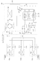
本参考技術の空調機(20)は、冷凍装置(20)によって構成されている。空調機(20)は、図1に示すように、1台の室外ユニット(64)と3台の室内ユニット(61a,61b,61c)とを備えている。なお、室内ユニット(61a,61b,61c)の台数は、単なる例示である。
《Reference technology》
This reference technique of the air conditioner (20) is constituted by a refrigerating apparatus (20). As shown in FIG. 1, the air conditioner (20) includes one outdoor unit (64) and three indoor units (61a, 61b, 61c). The number of indoor units (61a, 61b, 61c) is merely an example.
上記空調機(20)は、冷媒回路(10)を備えている。この冷媒回路(10)は、二酸化炭素(CO2)が冷媒として充填された閉回路である。冷媒回路(10)は、1つの室外回路(14)と、3つの室内回路(11a,11b,11c)とを備えている。これらの室内回路(11a,11b,11c)は、第1連絡管(15)及び第2連絡管(16)によって室外回路(14)に並列に接続されている。具体的に、第1連絡管(15)は、一端が室外回路(14)の第1閉鎖弁(17)に接続され、他端が3つに分岐して各室内回路(11a,11b,11c)の液側端に接続されている。第2連絡管(16)は、一端が室外回路(14)の第2閉鎖弁(18)に接続され、他端が3つに分岐して各室内回路(11a,11b,11c)のガス側端に接続されている。 The air conditioner (20) includes a refrigerant circuit (10). This refrigerant circuit (10) is a closed circuit filled with carbon dioxide (CO 2 ) as a refrigerant. The refrigerant circuit (10) includes one outdoor circuit (14) and three indoor circuits (11a, 11b, 11c). These indoor circuits (11a, 11b, 11c) are connected in parallel to the outdoor circuit (14) by the first connecting pipe (15) and the second connecting pipe (16). Specifically, one end of the first communication pipe (15) is connected to the first shut-off valve (17) of the outdoor circuit (14), and the other end is branched into three to each indoor circuit (11a, 11b, 11c). ) Connected to the liquid side end. One end of the second communication pipe (16) is connected to the second shut-off valve (18) of the outdoor circuit (14), and the other end branches into three, and the gas side of each indoor circuit (11a, 11b, 11c) Connected to the end.
各室内回路(11a,11b,11c)は、各室内ユニット(61a,61b,61c)に1つずつ収容されている。各室内回路(11a,11b,11c)には、そのガス側端から液側端へ向かって順に、室内熱交換器(41a,41b,41c)と、室内膨張弁(51a,51b,51c)とが設けられている。各室内ユニット(61a,61b,61c)には、各室内熱交換器(41a,41b,41c)に室内空気を送るための室内ファンが設けられている(図示省略)。 Each indoor circuit (11a, 11b, 11c) is accommodated in each indoor unit (61a, 61b, 61c). Each indoor circuit (11a, 11b, 11c) includes an indoor heat exchanger (41a, 41b, 41c), an indoor expansion valve (51a, 51b, 51c) in order from the gas side end to the liquid side end. Is provided. Each indoor unit (61a, 61b, 61c) is provided with an indoor fan for sending indoor air to each indoor heat exchanger (41a, 41b, 41c) (not shown).
室内熱交換器(41a,41b,41c)は、クロスフィン型のフィン・アンド・チューブ熱交換器として構成されている。室内熱交換器(41a,41b,41c)へは、室内ファンによって室内空気が供給される。室内熱交換器(41a,41b,41c)では、室内空気と冷媒との間で熱交換が行われる。また、室内膨張弁(51a,51b,51c)は、開度可変の電子膨張弁によって構成されている。 The indoor heat exchangers (41a, 41b, 41c) are configured as cross fin type fin-and-tube heat exchangers. Indoor air is supplied to the indoor heat exchangers (41a, 41b, 41c) by an indoor fan. In the indoor heat exchanger (41a, 41b, 41c), heat is exchanged between the indoor air and the refrigerant. The indoor expansion valves (51a, 51b, 51c) are constituted by electronic expansion valves with variable opening.
室外回路(14)は、室外ユニット(64)に収容されている。室外回路(14)には、圧縮・膨張ユニット(26)、室外熱交換器(44)、冷媒調整タンク(35)、室外膨張弁(43)、四路切換弁(25)、及びブリッジ回路(24)が設けられている。室外ユニット(64)には、室外熱交換器(44)に室外空気を送るための室外ファンが設けられている(図示省略)。 The outdoor circuit (14) is accommodated in the outdoor unit (64). The outdoor circuit (14) includes a compression / expansion unit (26), an outdoor heat exchanger (44), a refrigerant adjustment tank (35), an outdoor expansion valve (43), a four-way selector valve (25), and a bridge circuit ( 24) is provided. The outdoor unit (64) is provided with an outdoor fan for sending outdoor air to the outdoor heat exchanger (44) (not shown).
圧縮・膨張ユニット(26)は、縦長で円筒形の密閉容器であるケーシング(21)を備えている。ケーシング(21)内には、圧縮機(30)と膨張機(31)と電動機(32)とが収容されている。ケーシング(21)内では、圧縮機(30)と電動機(32)と膨張機(31)とが下から上へ向かって順に配置され、回転軸によって互いに連結されている。 The compression / expansion unit (26) includes a casing (21) which is a vertically long and cylindrical sealed container. A compressor (30), an expander (31), and an electric motor (32) are accommodated in the casing (21). In the casing (21), the compressor (30), the electric motor (32), and the expander (31) are arranged in order from the bottom to the top, and are connected to each other by a rotating shaft.
圧縮機(30)及び膨張機(31)は、何れも容積型の流体機械(揺動ピストン型のロータリ流体機械、ローリングピストン型のロータリ流体機械、スクロール流体機械など)によって構成されている。圧縮機(30)は、吸入した冷媒(CO2)をその臨界圧力以上にまで圧縮する。膨張機(31)は、流入した冷媒(CO2)を膨張させて動力(膨張動力)を回収する。圧縮機(30)は、膨張機(31)で回収された動力と、電動機(32)へ通電して得られる動力との両方によって回転駆動される。電動機(32)には、図外のインバータから所定周波数の交流電力が供給される。圧縮機(30)は、電動機(32)へ供給される電力の周波数を変更することで、その容量が可変に構成されている。圧縮機(30)と膨張機(31)とは、常に同じ回転速度で回転する。 Each of the compressor (30) and the expander (31) is constituted by a positive displacement fluid machine (such as a swinging piston type rotary fluid machine, a rolling piston type rotary fluid machine, and a scroll fluid machine). The compressor (30) compresses the sucked refrigerant (CO 2 ) to the critical pressure or higher. The expander (31) expands the inflowing refrigerant (CO 2 ) to recover power (expansion power). The compressor (30) is rotationally driven by both the power recovered by the expander (31) and the power obtained by energizing the electric motor (32). The electric motor (32) is supplied with AC power having a predetermined frequency from an inverter (not shown). The compressor (30) has a variable capacity by changing the frequency of the electric power supplied to the electric motor (32). The compressor (30) and the expander (31) always rotate at the same rotational speed.
室外熱交換器(44)は、クロスフィン型のフィン・アンド・チューブ熱交換器として構成されている。室外熱交換器(44)へは、室外ファンによって室外空気が供給される。室外熱交換器(44)では、室外空気と冷媒との間で熱交換が行われる。室外熱交換器(44)は、一端が四路切換弁(25)の第3のポートに接続され、他端が室外膨張弁(43)に接続されている。 The outdoor heat exchanger (44) is configured as a cross-fin type fin-and-tube heat exchanger. Outdoor air is supplied to the outdoor heat exchanger (44) by an outdoor fan. In the outdoor heat exchanger (44), heat is exchanged between the outdoor air and the refrigerant. One end of the outdoor heat exchanger (44) is connected to the third port of the four-way switching valve (25), and the other end is connected to the outdoor expansion valve (43).
冷媒調整タンク(35)は、縦長で円筒状の密閉容器である。冷媒調整タンク(35)は、冷媒回路(10)を循環する冷媒の量を調節するためのものであり、冷媒配管を介して膨張機(31)の流出側に接続されている。この冷媒配管は、冷媒調整タンク(35)内のガス空間に開口するように、冷媒調整タンク(35)内において上寄りの位置に開口している。冷媒調整タンク(35)の底部には、ブリッジ回路(24)に接続される液配管(38)が接続されている。 The refrigerant adjustment tank (35) is a vertically long and cylindrical sealed container. The refrigerant adjustment tank (35) is for adjusting the amount of refrigerant circulating in the refrigerant circuit (10), and is connected to the outflow side of the expander (31) via a refrigerant pipe. The refrigerant pipe is opened at an upper position in the refrigerant adjustment tank (35) so as to open into the gas space in the refrigerant adjustment tank (35). A liquid pipe (38) connected to the bridge circuit (24) is connected to the bottom of the refrigerant adjustment tank (35).
ブリッジ回路(24)は、4つの逆止弁(CV-1〜CV-4)をブリッジ状に接続したものである。このブリッジ回路(24)における第1逆止弁(CV-1)及び第4逆止弁(CV-4)の流入側には、液配管(38)が接続されている。第2逆止弁(CV-2)及び第3逆止弁(CV-3)の流出側は、膨張機(31)の流入側に接続されている。第1逆止弁(CV-1)の流出側及び第2逆止弁(CV-2)の流入側は、第1閉鎖弁(17)に接続されている。第3逆止弁(CV-3)の流入側及び第4逆止弁(CV-4)の流出側は、室外膨張弁(43)に接続されている。 The bridge circuit (24) is formed by connecting four check valves (CV-1 to CV-4) in a bridge shape. A liquid pipe (38) is connected to the inflow side of the first check valve (CV-1) and the fourth check valve (CV-4) in the bridge circuit (24). The outflow sides of the second check valve (CV-2) and the third check valve (CV-3) are connected to the inflow side of the expander (31). The outflow side of the first check valve (CV-1) and the inflow side of the second check valve (CV-2) are connected to the first closing valve (17). The inflow side of the third check valve (CV-3) and the outflow side of the fourth check valve (CV-4) are connected to the outdoor expansion valve (43).
四路切換弁(25)の第1のポートは、圧縮機(30)の吸入側に接続されている。第2のポートは、第2閉鎖弁(18)に接続されている。第3のポートは、室外熱交換器(44)に接続されている。第4のポートは、圧縮機(30)の吐出側に接続されている。四路切換弁(25)は、第1のポートと第2のポートとが連通して第3のポートと第4のポートとが連通する状態(図1に実線で示す第1状態)と、第1のポートと第3のポートとが連通して第2のポートと第4のポートとが連通する状態(図1に破線で示す第2状態)とが切り換え自在に構成されている。 The first port of the four-way switching valve (25) is connected to the suction side of the compressor (30). The second port is connected to the second closing valve (18). The third port is connected to the outdoor heat exchanger (44). The fourth port is connected to the discharge side of the compressor (30). The four-way selector valve (25) has a state in which the first port and the second port communicate with each other and the third port and the fourth port communicate with each other (a first state indicated by a solid line in FIG. 1); A state in which the first port and the third port communicate with each other and the second port and the fourth port communicate with each other (second state indicated by a broken line in FIG. 1) is configured to be switchable.
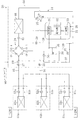
上記室外回路(14)には、液インジェクション配管を構成する液インジェクション配管(39)と、ガスインジェクション配管を構成するガスインジェクション配管(37)とが設けられている。液インジェクション配管(39)は、その一端が冷媒調整タンク(35)の底部に、他端が圧縮機(30)の吸入側にそれぞれ接続されている。液インジェクション配管(39)の途中には、液側流量調節機構としての液側調節弁(40)が設けられている。ガスインジェクション配管(37)は、その一端が冷媒調整タンク(35)の頂部に、他端が圧縮機(30)の吸入側にそれぞれ接続されている。ガスインジェクション配管(37)の途中には、ガス側流量調節機構としてのガス側調節弁(36)が設けられている。液側調節弁(40)とガス側調節弁(36)は、何れも開度可変の電子膨張弁によって構成されている。 The outdoor circuit (14) is provided with a liquid injection pipe (39) constituting a liquid injection pipe and a gas injection pipe (37) constituting a gas injection pipe. One end of the liquid injection pipe (39) is connected to the bottom of the refrigerant adjustment tank (35), and the other end is connected to the suction side of the compressor (30). In the middle of the liquid injection pipe (39), a liquid side control valve (40) as a liquid side flow rate adjustment mechanism is provided. The gas injection pipe (37) has one end connected to the top of the refrigerant adjustment tank (35) and the other end connected to the suction side of the compressor (30). In the middle of the gas injection pipe (37), a gas side control valve (36) as a gas side flow rate adjusting mechanism is provided. Both the liquid side control valve (40) and the gas side control valve (36) are constituted by an electronic expansion valve having a variable opening.
上記空調機(20)には、制御手段としてのコントローラ(90)が設けられている。このコントローラ(90)は、液側調節弁(40)とガス側調節弁(36)の開度調節を行うように構成されている。具体的に、このコントローラ(90)は、圧縮機(30)の吐出冷媒温度の目標値を制御目標値として設定し、圧縮機(30)の吐出冷媒温度の実測値が制御目標値となるように液側調節弁(40)とガス側調節弁(36)の開度を調節する。その際、コントローラ(90)は、その時点の運転状態において冷凍サイクルの成績係数(COP)が最高となるような冷凍サイクルの高圧の値を、制御目標値に設定する。 The air conditioner ( 20 ) is provided with a controller (90) as control means. The controller (90) is configured to adjust the opening of the liquid side control valve (40) and the gas side control valve (36). Specifically, the controller (90) sets the target value of the refrigerant discharge temperature of the compressor (30) as a control target value so that the measured value of the refrigerant discharge temperature of the compressor (30) becomes the control target value. The opening degree of the liquid side control valve (40) and the gas side control valve (36) is adjusted. At that time, the controller (90) sets the value of the high pressure of the refrigeration cycle such that the coefficient of performance (COP) of the refrigeration cycle is maximum in the operation state at that time as the control target value.
−運転動作−
上記空調機(20)の運転動作について説明する。この空調機(20)は、冷房運転と暖房運転とが実行可能になっており、四路切換弁(25)によって運転の切り換えが行われる。
-Driving action-
The operation of the air conditioner (20) will be described. The air conditioner (20) can perform a cooling operation and a heating operation, and the operation is switched by the four-way switching valve (25).
《冷房運転》
冷房運転時には、四路切換弁(25)が図1に実線で示す第1状態に設定される。室内膨張弁(51a,51b,51c)の開度は適宜調節される。室外膨張弁(43)の開度は全開に設定される。この状態で圧縮機(30)を駆動すると、冷媒回路(10)で冷媒が循環して冷凍サイクルが行われる。その際、室外熱交換器(44)が凝縮器として機能し、各室内熱交換器(41a,41b,41c)が蒸発器として機能する。
《Cooling operation》
During the cooling operation, the four-way selector valve (25) is set to the first state indicated by the solid line in FIG. The opening degree of the indoor expansion valves (51a, 51b, 51c) is appropriately adjusted. The opening degree of the outdoor expansion valve (43) is set to fully open. When the compressor (30) is driven in this state, the refrigerant circulates in the refrigerant circuit (10) to perform a refrigeration cycle. At that time, the outdoor heat exchanger (44) functions as a condenser, and each indoor heat exchanger (41a, 41b, 41c) functions as an evaporator.
具体的に、圧縮機(30)からは、臨界圧力よりも高圧となった冷媒が吐出される。この高圧の冷媒は、室外熱交換器(44)へ流入し、室外空気へ放熱して凝縮する。室外熱交換器(44)で凝縮した冷媒は、膨張機(31)に流入して減圧される。膨張機(31)で減圧された冷媒は、冷媒調整タンク(35)に流入して液冷媒とガス冷媒とに分離される。冷媒調整タンク(35)内の液冷媒は、各室内回路(11a,11b,11c)へ分配される。 Specifically, the refrigerant having a pressure higher than the critical pressure is discharged from the compressor (30). This high-pressure refrigerant flows into the outdoor heat exchanger (44), dissipates heat to the outdoor air, and condenses. The refrigerant condensed in the outdoor heat exchanger (44) flows into the expander (31) and is depressurized. The refrigerant decompressed by the expander (31) flows into the refrigerant adjustment tank (35) and is separated into liquid refrigerant and gas refrigerant. The liquid refrigerant in the refrigerant adjustment tank (35) is distributed to each indoor circuit (11a, 11b, 11c).
各室内回路(11a,11b,11c)では、流入した冷媒が、室内膨張弁(51a,51b,51c)で減圧されて室内熱交換器(41a,41b,41c)へ流入し、室内空気と熱交換を行う。この熱交換により、冷媒は室内空気から吸熱して蒸発する一方、室内空気は冷却されて室内へ供給される。各室内熱交換器(41a,41b,41c)で蒸発した冷媒は、合流後に室外回路(14)へ流入して、圧縮機(30)へ吸入される。圧縮機(30)に吸入された冷媒は、再び圧縮されて吐出される。 In each indoor circuit (11a, 11b, 11c), the refrigerant that has flowed in is decompressed by the indoor expansion valves (51a, 51b, 51c), flows into the indoor heat exchanger (41a, 41b, 41c), and heats the indoor air and heat. Exchange. By this heat exchange, the refrigerant absorbs heat from the room air and evaporates, while the room air is cooled and supplied to the room. The refrigerant evaporated in each indoor heat exchanger (41a, 41b, 41c) flows into the outdoor circuit (14) after joining, and is sucked into the compressor (30). The refrigerant sucked into the compressor (30) is compressed again and discharged.
冷房運転における冷凍サイクルでは、圧縮機(30)から吐出された冷媒が、膨張機(31)で減圧された後に各室内膨張弁(51a,51b,51c)で減圧される。膨張機(31)から各室内膨張弁(51a,51b,51c)に至るまでの間は冷凍サイクルにおける中間圧になるので、その間に配置された冷媒調整タンク(35)内の圧力は冷凍サイクルにおける中間圧になる。冷房運転では、各室内膨張弁(51a,51b,51c)が低圧側膨張機構として機能する。 In the refrigeration cycle in the cooling operation, the refrigerant discharged from the compressor (30) is decompressed by the indoor expansion valves (51a, 51b, 51c) after being decompressed by the expander (31). Since the pressure from the expander (31) to each indoor expansion valve (51a, 51b, 51c) is an intermediate pressure in the refrigeration cycle, the pressure in the refrigerant adjustment tank (35) disposed between them is Become intermediate pressure. In the cooling operation, each indoor expansion valve (51a, 51b, 51c) functions as a low-pressure side expansion mechanism.
《暖房運転》
暖房運転時には、四路切換弁(25)が図1に破線で示す第2状態に設定される。室外膨張弁(43)の開度は適宜調節される。室内膨張弁(51a,51b,51c)の開度は全開に設定される。この状態で圧縮機(30)を駆動すると、冷媒回路(10)で冷媒が循環して冷凍サイクルが行われる。その際、各室内熱交換器(41a,41b,41c)が凝縮器として機能し、室外熱交換器(44)が蒸発器として機能する。
《Heating operation》
During the heating operation, the four-way selector valve (25) is set to the second state indicated by a broken line in FIG. The opening degree of the outdoor expansion valve (43) is adjusted as appropriate. The opening degree of the indoor expansion valves (51a, 51b, 51c) is set to fully open. When the compressor (30) is driven in this state, the refrigerant circulates in the refrigerant circuit (10) to perform a refrigeration cycle. In that case, each indoor heat exchanger (41a, 41b, 41c) functions as a condenser, and an outdoor heat exchanger (44) functions as an evaporator.
具体的に、圧縮機(30)からは、臨界圧力よりも高圧となった冷媒が吐出される。この高圧の冷媒は、各室内回路(11a,11b,11c)へ分配される。各室内回路(11a,11b,11c)では、流入した冷媒が室内熱交換器(41a,41b,41c)へ流入し、室内空気と熱交換を行う。この熱交換により、冷媒は室内空気へ放熱して凝縮する一方、室内空気は加熱されて室内へ供給される。各室内熱交換器(41a,41b,41c)で凝縮した冷媒は、合流後に室外回路(14)へ流入する。 Specifically, the refrigerant having a pressure higher than the critical pressure is discharged from the compressor (30). This high-pressure refrigerant is distributed to each indoor circuit (11a, 11b, 11c). In each indoor circuit (11a, 11b, 11c), the refrigerant that has flowed flows into the indoor heat exchanger (41a, 41b, 41c) and exchanges heat with room air. By this heat exchange, the refrigerant dissipates heat to the indoor air and condenses, while the indoor air is heated and supplied to the room. The refrigerant condensed in each indoor heat exchanger (41a, 41b, 41c) flows into the outdoor circuit (14) after joining.
室外回路(14)へ流入した冷媒は、膨張機(31)に流入して減圧される。膨張機(31)で減圧された冷媒は、冷媒調整タンク(35)に流入して液冷媒とガス冷媒とに分離される。冷媒調整タンク(35)内の液冷媒は、室外膨張弁(43)で減圧されて室外熱交換器(44)へ流入する。室外熱交換器(44)では、流入した冷媒が室外空気と熱交換を行う。この熱交換により、冷媒が室外空気から吸熱して蒸発する。室外熱交換器(44)で蒸発した冷媒は、圧縮機(30)へ吸入され、再び圧縮されて吐出される。 The refrigerant that has flowed into the outdoor circuit (14) flows into the expander (31) and is depressurized. The refrigerant decompressed by the expander (31) flows into the refrigerant adjustment tank (35) and is separated into liquid refrigerant and gas refrigerant. The liquid refrigerant in the refrigerant adjustment tank (35) is decompressed by the outdoor expansion valve (43) and flows into the outdoor heat exchanger (44). In the outdoor heat exchanger (44), the refrigerant flowing in exchanges heat with the outdoor air. By this heat exchange, the refrigerant absorbs heat from the outdoor air and evaporates. The refrigerant evaporated in the outdoor heat exchanger (44) is sucked into the compressor (30), compressed again, and discharged.
暖房運転における冷凍サイクルでは、圧縮機(30)から吐出された冷媒が、膨張機(31)で減圧された後に室外膨張弁(43)で減圧される。膨張機(31)から室外膨張弁(43)に至るまでの間は冷凍サイクルにおける中間圧になるので、その間に配置された冷媒調整タンク(35)内の圧力は冷凍サイクルにおける中間圧になる。暖房運転では、室外膨張弁(43)が低圧側膨張機構として機能する。 In the refrigeration cycle in the heating operation, the refrigerant discharged from the compressor (30) is decompressed by the expander (31) and then decompressed by the outdoor expansion valve (43). Since the pressure from the expander (31) to the outdoor expansion valve (43) is an intermediate pressure in the refrigeration cycle, the pressure in the refrigerant adjustment tank (35) disposed therebetween becomes an intermediate pressure in the refrigeration cycle. In the heating operation, the outdoor expansion valve (43) functions as a low pressure side expansion mechanism.
−コントローラの制御動作−
先ず、液側調節弁(40)やガス側調節弁(36)の開度を変化させた場合に、冷凍サイクルの運転状態がどの様に変化するかを説明する。
-Controller control action-
First, how the operating state of the refrigeration cycle changes when the opening of the liquid side control valve (40) or the gas side control valve (36) is changed will be described.
図2のモリエル線図(圧力−エンタルピ線図)には、冷媒の蒸発圧力(即ち冷凍サイクルの低圧)がPLであって、ガスクーラ出口における冷媒温度がTgcである冷凍サイクルを図示してある。この運転状態で最高の成績係数が得られる冷凍サイクルは、A−B−C−D−E−Fで表された冷凍サイクルであるとする。つまり、圧縮機(30)から吐出される冷媒の温度がTdとなった場合(即ち冷凍サイクルの高圧がPHとなった場合)に、冷凍サイクルのCOPが最高になると仮定する。 Mollier diagram of FIG. 2 - in (pressure-enthalpy diagram) the evaporation pressure of the refrigerant (i.e., the low pressure of the refrigeration cycle) is a P L, the refrigerant temperature at the gas cooler outlet is shown a refrigeration cycle is T gc is there. It is assumed that the refrigeration cycle in which the highest coefficient of performance is obtained in this operating state is the refrigeration cycle represented by A-B-C-D-E-F. That is, it is assumed when the temperature of the refrigerant discharged from the compressor (30) becomes T d (i.e. if the high pressure of the refrigeration cycle becomes P H), and COP of the refrigeration cycle becomes the highest.
なお、冷凍サイクルの高圧が冷媒の臨界圧力を超えるいわゆる超臨界サイクルでは、冷媒の蒸発圧力(即ち冷凍サイクルの低圧)と、圧縮機(30)へ吸入される冷媒の状態(具体的には過熱度あるいは湿り度)と、ガスクーラ出口での冷媒温度とを決めれば、それに応じて冷凍サイクルのCOPが最高となる冷凍サイクルの高圧を特定できる。 In a so-called supercritical cycle in which the high pressure of the refrigeration cycle exceeds the critical pressure of the refrigerant, the evaporation pressure of the refrigerant (that is, the low pressure of the refrigeration cycle) and the state of the refrigerant sucked into the compressor (30) (specifically, overheating) If the refrigerant temperature at the gas cooler outlet is determined, the high pressure of the refrigeration cycle at which the COP of the refrigeration cycle is maximized can be specified accordingly.
冷媒回路(10)において、A'−B'−C'−D'−E−Fで表された冷凍サイクルが行われていたとする。このときには、圧縮機(30)へ吸入される冷媒の状態が点A'の状態となっている。点A'の状態の冷媒は、点Aの状態の冷媒に比べて密度が低くなっている。つまり、冷凍サイクルのCOPが最高となる運転条件を満たすには、圧縮機(30)の通過冷媒量が膨張機(31)の通過冷媒量に対して不足していることになる。 It is assumed that the refrigeration cycle represented by A′-B′-C′-D′-EF has been performed in the refrigerant circuit (10). At this time, the state of the refrigerant sucked into the compressor (30) is the state of point A ′. The refrigerant in the state of point A ′ has a lower density than the refrigerant in the state of point A. That is, in order to satisfy the operating condition in which the COP of the refrigeration cycle is maximized, the amount of refrigerant passing through the compressor (30) is insufficient with respect to the amount of refrigerant passing through the expander (31).
この場合に、液インジェクション配管(39)からの液冷媒の供給を開始し、あるいは液インジェクション配管(39)からの液冷媒の供給量を増大させると、圧縮機(30)へ吸入される冷媒は、点A'の状態から点Aの状態へ近付き、その密度が上昇する。圧縮機(30)へ吸入される冷媒の密度が上昇すると、それに伴って膨張機(31)へ流入する冷媒の密度も上昇する。このため、点C'は、温度Tgcの等温線上を密度が大きくなる方向へ移動し、点Cに近付いてゆく。そして、冷凍サイクルの高圧PH'が上昇して圧力PHに近付くと共に、圧縮機(30)の吐出冷媒の温度が低下して温度Tdに近付くこととなり、冷凍サイクル全体がA−B−C−D−E−Fで表される理想的なものに近くなってゆく。 In this case, if the supply of the liquid refrigerant from the liquid injection pipe (39) is started or the supply amount of the liquid refrigerant from the liquid injection pipe (39) is increased, the refrigerant sucked into the compressor (30) is The point A ′ approaches the point A state, and the density increases. When the density of the refrigerant sucked into the compressor (30) increases, the density of the refrigerant flowing into the expander (31) increases accordingly. For this reason, the point C ′ moves on the isotherm of the temperature T gc in the direction of increasing the density, and approaches the point C. Then, the high pressure P H ′ of the refrigeration cycle increases and approaches the pressure P H, and the temperature of the refrigerant discharged from the compressor (30) decreases and approaches the temperature T d , so that the entire refrigeration cycle is AB− It becomes closer to the ideal represented by C-D-E-F.
また、冷媒回路(10)において、A''−B''−C''−D''−E−Fで表された冷凍サイクルが行われていたとする。このときには、圧縮機(30)へ吸入される冷媒の状態が点A''の状態となっている。点A''の状態の冷媒は、点Aの状態の冷媒に比べて密度が高くなっている。つまり、冷凍サイクルのCOPが最高となる運転条件を満たすには、圧縮機(30)の通過冷媒量が膨張機(31)の通過冷媒量に対して過多になっていることになる。 In the refrigerant circuit (10), it is assumed that the refrigeration cycle represented by A ″ -B ″ -C ″ -D ″ -EF has been performed. At this time, the state of the refrigerant sucked into the compressor (30) is the state of point A ″. The refrigerant in the state of point A ″ has a higher density than the refrigerant in the state of point A. That is, in order to satisfy the operating condition in which the COP of the refrigeration cycle is maximized, the amount of refrigerant passing through the compressor (30) is excessive with respect to the amount of refrigerant passing through the expander (31).
この場合に、ガスインジェクション配管(37)からのガス冷媒の供給を開始し、あるいはガスインジェクション配管(37)からのガス冷媒の供給量を増大させると、圧縮機(30)へ吸入される冷媒は、点A''の状態から点Aの状態へ近付き、その密度が低下する。圧縮機(30)へ吸入される冷媒の密度が低下すると、それに伴って膨張機(31)へ流入する冷媒の密度も低下する。このため、点C''は、温度Tgcの等温線上を密度が小さくなる方向へ移動し、点Cに近付いてゆく。そして、冷凍サイクルの高圧PH''が低下して圧力PHに近付くと共に、圧縮機(30)の吐出冷媒の温度が上昇して温度Tdに近付くこととなり、冷凍サイクル全体がA−B−C−D−E−Fで表される理想的なものに近くなってゆく。 In this case, if the supply of the gas refrigerant from the gas injection pipe (37) is started or the supply amount of the gas refrigerant from the gas injection pipe (37) is increased, the refrigerant sucked into the compressor (30) is , The state of the point A ″ approaches the state of the point A, and the density decreases. When the density of the refrigerant sucked into the compressor (30) decreases, the density of the refrigerant flowing into the expander (31) also decreases accordingly. For this reason, the point C ″ moves in the direction of decreasing density on the isotherm of the temperature T gc and approaches the point C. Then, the closer the pressure P H to decrease pressure P H '' of the refrigeration cycle, the temperature of the refrigerant discharged from the compressor (30) becomes closer to the temperature T d to rise, the whole refrigeration cycle A-B -It becomes closer to the ideal represented by C-D-E-F.
次に、コントローラ(90)の制御動作について説明する。上述のように、コントローラ(90)は、圧縮機(30)からの吐出冷媒温度に関する制御目標値を設定する。具体的に、コントローラ(90)は、冷凍サイクルの低圧圧力の実測値とガスクーラ出口の冷媒温度の実測値とを、センサ等から取得する。一方、このコントローラ(90)は、冷凍サイクルのCOPが最高となる圧縮機(30)の吐出冷媒温度を、冷凍サイクルの低圧圧力とガスクーラ出口の冷媒温度との関数として予め記憶している。その際、圧縮機(30)の吸入冷媒の状態は、例えば「過熱度5℃である」あるいは「飽和状態である」というように、予め定めておく。コントローラ(90)は、この記憶する関数に取得した実測値を代入して演算を行い、それによって得られた値を制御目標値に設定する。 Next, the control operation of the controller (90) will be described. As described above, the controller (90) sets the control target value related to the refrigerant temperature discharged from the compressor (30). Specifically, the controller (90) acquires an actual measurement value of the low pressure of the refrigeration cycle and an actual measurement value of the refrigerant temperature at the gas cooler outlet from a sensor or the like. On the other hand, the controller (90) stores in advance the refrigerant temperature discharged from the compressor (30) at which the COP of the refrigeration cycle is maximum as a function of the low pressure of the refrigeration cycle and the refrigerant temperature at the gas cooler outlet. At this time, the state of the refrigerant sucked in the compressor (30) is determined in advance, for example, “superheat degree is 5 ° C.” or “saturated state”. The controller (90) performs an operation by substituting the actually measured value obtained for the stored function, and sets the value obtained thereby as the control target value.
そして、コントローラ(90)は、設定した制御目標値を圧縮機(30)の吐出冷媒温度の実測値と対比し、その結果に基づいて液側調節弁(40)やガス側調節弁(36)の開度を制御する。 The controller (90) compares the set control target value with the actually measured value of the refrigerant discharge temperature of the compressor (30), and based on the result, the liquid side control valve (40) and the gas side control valve (36) To control the opening degree.
例えば、圧縮機(30)の吐出冷媒温度の実測値が制御目標値よりも高かったとする。このとき、ガス側調節弁(36)が開いている状態であれば、コントローラ(90)はガス側調節弁(36)の開度を絞ってゆく。ガス側調節弁(36)が全閉になっても依然として圧縮機(30)の吐出冷媒温度の実測値が制御目標値よりも高ければ、コントローラ(90)は液側調節弁(40)の開度を増大させてゆく。逆に、圧縮機(30)の吐出冷媒温度の実測値が制御目標値よりも低かったとする。このとき、液側調節弁(40)が開いている状態であれば、コントローラ(90)は液側調節弁(40)の開度を絞ってゆく。液側調節弁(40)が全閉になっても依然として圧縮機(30)の吐出冷媒温度の実測値が制御目標値よりも低ければ、コントローラ(90)はガス側調節弁(36)の開度を増大させてゆく。 For example, it is assumed that the actually measured value of the discharge refrigerant temperature of the compressor (30) is higher than the control target value. At this time, if the gas side control valve (36) is in an open state, the controller (90) reduces the opening of the gas side control valve (36). If the measured value of the refrigerant discharge temperature of the compressor (30) is still higher than the control target value even after the gas side control valve (36) is fully closed, the controller (90) opens the liquid side control valve (40). Increase the degree. Conversely, it is assumed that the actual measured value of the refrigerant discharge temperature of the compressor (30) is lower than the control target value. At this time, if the liquid side control valve (40) is in an open state, the controller (90) reduces the opening of the liquid side control valve (40). If the measured value of the refrigerant discharge temperature of the compressor (30) is still lower than the control target value even when the liquid side control valve (40) is fully closed, the controller (90) opens the gas side control valve (36). Increase the degree.
−参考技術の効果−
本参考技術では、冷媒調整タンク(35)内の圧力を冷凍サイクルにおける中間圧にすることで、冷媒調整タンク(35)内の冷媒と圧縮機(30)に吸入される冷媒との圧力差が大きくなるようにしている。冷媒調整タンク(35)内の冷媒と圧縮機(30)に吸入される冷媒との圧力差が大きくなると、冷媒調整タンク(35)から圧縮機(30)へ冷媒が流れやすくなり、冷媒調整タンク(35)から圧縮機(30)へ供給可能な液冷媒の量が従来に比べて増加する。従って、液流量調節機構(40)の操作によって圧縮機(30)が吸入する冷媒の密度を従来より大きく変化させることが可能になるので、圧縮機(30)の通過冷媒量と膨張機(31)の通過冷媒量とのバランスを調節する能力を向上させることができる。
-Effect of reference technology-
In this reference technology , the pressure difference between the refrigerant in the refrigerant adjustment tank (35) and the refrigerant sucked into the compressor (30) is obtained by setting the pressure in the refrigerant adjustment tank (35) to an intermediate pressure in the refrigeration cycle. I try to get bigger. When the pressure difference between the refrigerant in the refrigerant adjustment tank (35) and the refrigerant sucked into the compressor (30) increases, the refrigerant easily flows from the refrigerant adjustment tank (35) to the compressor (30). The amount of liquid refrigerant that can be supplied from (35) to the compressor (30) increases compared to the conventional case. Accordingly, the operation of the liquid flow rate adjusting mechanism (40) makes it possible to change the density of the refrigerant sucked by the compressor (30) more than before, so that the amount of refrigerant passing through the compressor (30) and the expander (31 ), The ability to adjust the balance with the amount of refrigerant passing through can be improved.
また、本参考技術では、冷媒調整タンク(35)内のガス冷媒を圧縮機(30)へ供給するためのガスインジェクション配管(37)を設けることで、気液分離器(35)内がガス冷媒が溜まっていく状態にならないようにしている。従って、膨張機(31)から流入する冷媒が冷媒調整タンク(35)で液冷媒とガス冷媒とに分離しやすくなる。 In addition, in this reference technology , the gas-liquid separator (35) is provided with a gas injection pipe (37) for supplying the gas refrigerant in the refrigerant adjustment tank (35) to the compressor (30). To prevent it from accumulating. Therefore, the refrigerant flowing from the expander (31) is easily separated into the liquid refrigerant and the gas refrigerant in the refrigerant adjustment tank (35).
また、本参考技術では、ガスインジェクション配管(37)を通じて圧縮機(30)へ供給される冷媒の量がガス流量調節機構(36)によって調節可能になっている。従って、適切な運転条件に設定しようとすると圧縮機(30)を通過できる冷媒量が膨張機(31)を通過できる冷媒量に比べて過多となるような場合でも、ガスインジェクション配管(37)を通じて圧縮機(30)へ冷媒を供給することで、圧縮機(30)を通過できる冷媒量と膨張機(31)を通過できる冷媒量とをバランスさせることが可能となる。 Further, in the present reference technique , the amount of the refrigerant supplied to the compressor (30) through the gas injection pipe (37) can be adjusted by the gas flow rate adjusting mechanism (36). Therefore, even if the amount of refrigerant that can pass through the compressor (30) is excessive compared to the amount of refrigerant that can pass through the expander (31) when trying to set the appropriate operating conditions, the gas injection pipe (37) is used. By supplying the refrigerant to the compressor (30), it is possible to balance the amount of refrigerant that can pass through the compressor (30) and the amount of refrigerant that can pass through the expander (31).
また、本参考技術では、上述したように、冷媒調整タンク(35)内の圧力が冷凍サイクルにおける中間圧になっているので、冷媒調整タンク(35)内の冷媒と圧縮機(30)に吸入される冷媒との圧力差が大きい。従って、冷媒調整タンク(35)から圧縮機(30)へ比較的多くのガス冷媒を供給することができ、ガス流量調節機構(36)の操作によって圧縮機(30)が吸入する冷媒の密度を比較的大きく低下させることが可能になる。よって、適切な運転条件に設定しようとすると圧縮機(30)を通過できる冷媒量が膨張機(31)を通過できる冷媒量に比べて過多となる運転状態に対して、圧縮機(30)の通過冷媒量と膨張機(31)の通過冷媒量とのバランスを調節する能力を向上させることができる。 Further, in this reference technology , as described above, since the pressure in the refrigerant adjustment tank (35) is an intermediate pressure in the refrigeration cycle, the refrigerant is sucked into the refrigerant in the refrigerant adjustment tank (35) and the compressor (30). The pressure difference with the refrigerant to be used is large. Therefore, a relatively large amount of gas refrigerant can be supplied from the refrigerant adjustment tank (35) to the compressor (30), and the density of refrigerant sucked by the compressor (30) can be reduced by operating the gas flow rate adjusting mechanism (36). It becomes possible to reduce it comparatively greatly. Therefore, when setting the appropriate operating conditions, the amount of refrigerant that can pass through the compressor (30) is excessive compared to the amount of refrigerant that can pass through the expander (31). The ability to adjust the balance between the amount of refrigerant passing through and the amount of refrigerant passing through the expander (31) can be improved.
また、本参考技術では、その時の運転状態で最高のCOPを得られるようにコントローラ(90)が制御目標値を設定する。従って、冷凍サイクルの運転状態が最適な状態になるように、圧縮機(30)を通過できる冷媒量と膨張機(31)を通過できる冷媒量とのバランスを調節することができる。 In this reference technique , the controller (90) sets the control target value so that the highest COP can be obtained in the operation state at that time. Therefore, the balance between the amount of refrigerant that can pass through the compressor (30) and the amount of refrigerant that can pass through the expander (31) can be adjusted so that the operation state of the refrigeration cycle becomes an optimum state.
−参考技術の変形例1−
参考技術の変形例1について説明する。この変形例1では、図3に示すように、液配管(38)とガスインジェクション配管(37)とに跨って内部熱交換器(45)が設けられている。内部熱交換器(45)は、液配管(38)の途中に設けられる第1流路(46)と、ガスインジェクション配管(37)の途中に設けられる第2流路(47)とを備えている。内部熱交換器(45)では、第1流路(46)と第2流路(47)とが互いに隣接する状態で配置され、第1流路(46)の冷媒と第2流路(47)の冷媒とが熱交換を行うように構成されている。
-Modification of reference technology 1-
A first modification of the reference technique will be described. In this
この変形例1では、ガスインジェクション配管(37)のガス側調節弁(36)で減圧された冷媒が、内部熱交換器(45)で冷媒調整タンク(35)内の液冷媒が流入する第1流路(46)の冷媒と熱交換を行うことによって加熱されてその密度が小さくなる。従って、ガス側調節弁(36)の操作によって圧縮機(30)が吸入する冷媒の密度をさらに大きく低下させることが可能になる。 In the first modification, the refrigerant decompressed by the gas side control valve (36) of the gas injection pipe (37) flows into the liquid refrigerant in the refrigerant adjustment tank (35) through the internal heat exchanger (45). Heat is exchanged with the refrigerant in the channel (46) to reduce its density. Therefore, the density of the refrigerant sucked by the compressor (30) can be further reduced by operating the gas side control valve (36).
また、この変形例1では、冷媒調整タンク(35)内からガスインジェクション配管(37)に流入する冷媒は飽和状態のガス冷媒である。このため、ガスインジェクション配管(37)を通じて圧縮機(30)へ向かう冷媒は内部熱交換器(45)で加熱されると過熱状態になる。これにより、冷房運転の際に、各室内熱交換器(41a,41b,41c)の出口における冷媒の過熱度を比較的小さな値に調節しても、各室内熱交換器(41a,41b,41c)から圧縮機(30)へ向かう冷媒には内部熱交換器(45)からの過熱状態の冷媒が合流するので、圧縮機(30)が吸入する冷媒の湿り度は、液圧縮によって圧縮機(30)の損傷を招くおそれがあるほどの高い状態にはなりにくい。従って、各室内熱交換器(41a,41b,41c)における熱交換量を増加させることができるので、空調機(20)の運転効率を向上させることができる。 In the first modification, the refrigerant flowing from the refrigerant adjustment tank (35) into the gas injection pipe (37) is a saturated gas refrigerant. For this reason, if the refrigerant which goes to a compressor (30) through gas injection piping (37) is heated with an internal heat exchanger (45), it will be in a superheated state. As a result, during the cooling operation, even if the superheat degree of the refrigerant at the outlet of each indoor heat exchanger (41a, 41b, 41c) is adjusted to a relatively small value, each indoor heat exchanger (41a, 41b, 41c) ) From the internal heat exchanger (45) joins the refrigerant going to the compressor (30), so the wetness of the refrigerant sucked by the compressor (30) is determined by liquid compression by the compressor ( 30) It is difficult to reach a high state that may cause damage. Therefore, since the heat exchange amount in each indoor heat exchanger (41a, 41b, 41c) can be increased, the operating efficiency of the air conditioner (20) can be improved.
−参考技術の変形例2−
参考技術の変形例2について説明する。この変形例2では、図4に示すように、液インジェクション配管(39)及び液側調節弁(40)だけが設けられており、ガスインジェクション配管(37)及びガス側調節弁(36)は省略されている。この冷媒回路(10)において、液インジェクション配管(39)は、その一端が冷媒調整タンク(35)の底部に、他端が圧縮機(30)の吸入側にそれぞれ接続されている。この点は、上記参考技術の場合と同様である。
-Modification of reference technology 2-
A
また、この変形例2のコントローラ(90)は、ガスインジェクション配管(37)及びガス側調節弁(36)を省略したことに伴い、液側調節弁(40)の開度調節だけを行うように構成されている。つまり、このコントローラ(90)は、圧縮機(30)の吐出冷媒温度の目標値を制御目標値として設定し、圧縮機(30)の吐出冷媒温度の実測値が制御目標値となるように液側調節弁(40)の開度を調節する。 Further, the controller (90) of the second modification only adjusts the opening degree of the liquid side control valve (40) in accordance with the omission of the gas injection pipe (37) and the gas side control valve (36). It is configured. That is, the controller (90) sets the target value of the refrigerant discharge temperature of the compressor (30) as a control target value, and sets the target value of the refrigerant discharge temperature of the compressor (30) so that the measured value becomes the control target value. Adjust the opening of the side control valve (40).
上記コントローラ(90)は、圧縮機(30)の吐出冷媒温度に関する制御目標値を設定する。その際、コントローラ(90)は、上記参考技術の場合と同様にして制御目標値を設定する。つまり、コントローラ(90)は、冷凍サイクルの低圧圧力の実測値とガスクーラ出口の冷媒温度の実測値とに基づいて演算を行い、冷凍サイクルのCOPが最高となる圧縮機(30)の吐出冷媒温度を算出し、その値を制御目標値に設定する。 The controller (90) sets a control target value related to the discharge refrigerant temperature of the compressor (30). At that time, the controller (90) sets the control target value in the same manner as in the above-described reference technique . That is, the controller (90) performs a calculation based on the measured value of the low pressure of the refrigeration cycle and the measured value of the refrigerant temperature at the gas cooler outlet, and discharge refrigerant temperature of the compressor (30) at which the COP of the refrigeration cycle is maximum. Is calculated and the value is set as the control target value.
そして、コントローラ(90)は、設定した制御目標値を圧縮機(30)の吐出冷媒温度の実測値と対比し、その結果に基づいて液側調節弁(40)の開度を制御する。つまり、コントローラ(90)は、圧縮機(30)の吐出冷媒温度の実測値が制御目標値よりも高ければ液側調節弁(40)の開度を拡大する一方、圧縮機(30)の吐出冷媒温度の実測値が制御目標値よりも低ければ液側調節弁(40)の開度を縮小する。 Then, the controller (90) compares the set control target value with the actually measured value of the discharge refrigerant temperature of the compressor (30), and controls the opening degree of the liquid side control valve (40) based on the result. That is, the controller (90) increases the opening of the liquid side control valve (40) while the measured value of the refrigerant discharge temperature of the compressor (30) is higher than the control target value, while the discharge of the compressor (30) If the measured value of the refrigerant temperature is lower than the control target value, the opening degree of the liquid side control valve (40) is reduced.
《発明の実施形態》
本発明の実施形態について説明する。本実施形態は、上記参考技術と、その変形例1及び2とについて、図5に示すように、室外回路(14)にバイパス通路としてのバイパス配管(58)を設けるようにしたものである。
<< Embodiment of the Invention >>
An embodiment of the present invention will be described. This embodiment, and the reference technology for its first and second modifications, as shown in FIG. 5, is obtained by so providing the bypass pipe (58) as a bypass passage to the outdoor circuit (14).
バイパス配管(58)は、膨張機(31)をバイパスするようにその膨張機(31)の上流と下流とを接続する。バイパス配管(58)には、バイパス量調節機構である開度可変の流量調節弁(59)が設けられている。この第2変形例では、コントローラ(90)が、液側調節弁(40)やガス側調節弁(36)を開度制御するだけでなく、流量調節弁(59)を開度制御するように構成されている。 The bypass pipe (58) connects the upstream and downstream of the expander (31) so as to bypass the expander (31). The bypass pipe (58) is provided with a variable flow rate adjustment valve (59) that is a bypass amount adjustment mechanism. In the second modification, the controller (90) not only controls the opening of the liquid side control valve (40) and the gas side control valve (36), but also controls the opening of the flow rate control valve (59). It is configured.
例えば、コントローラ(90)は、冷房運転において適切な運転条件に設定しようとすると圧縮機(30)を通過できる冷媒量が膨張機(31)を通過できる冷媒量に比べて過少となる場合に、流量調節弁(59)を開状態する。すると、膨張機(31)を通過する冷媒流量を減少し、圧縮機(30)を通過できる冷媒量と膨張機(31)を通過できる冷媒量とがバランスされる。この第2変形例によれば、圧縮機(30)の通過冷媒量と膨張機(31)の通過冷媒量とのバランスを調節する能力をさらに向上させることができる。 For example, if the controller (90) attempts to set the appropriate operating condition in the cooling operation, the amount of refrigerant that can pass through the compressor (30) is less than the amount of refrigerant that can pass through the expander (31). Open the flow control valve (59). Then, the flow rate of the refrigerant passing through the expander (31) is reduced, and the amount of refrigerant that can pass through the compressor (30) and the amount of refrigerant that can pass through the expander (31) are balanced. According to this second modification, the ability to adjust the balance between the amount of refrigerant passing through the compressor (30) and the amount of refrigerant passing through the expander (31) can be further improved.
《その他の実施形態》
上記実施形態および参考技術は、以下の変形例のように構成してもよい。
<< Other Embodiments >>
The embodiment and the reference technique may be configured as in the following modifications.
−第1変形例−
上記実施形態および参考技術について、コントローラ(90)が、液側調節弁(40)やガス側調節弁(36)を開度制御するだけでなく、冷房運転で室外膨張弁(43)を開度制御し、暖房運転で各室内膨張弁(51a,51b,51c)を開度制御するように構成されていてもよい。冷房運転では、各室内膨張弁(51a,51b,51c)が低圧側膨張機構し、室外膨張弁(43)が高圧側流量調節機構を構成する。暖房運転では、室外膨張弁(43)が低圧側膨張機構し、各室内膨張弁(51a,51b,51c)が高圧側流量調節機構を構成する。
-First modification-
In the above embodiment and the reference technique , the controller (90) not only controls the opening of the liquid side control valve (40) and the gas side control valve (36), but also opens the outdoor expansion valve (43) in the cooling operation. The indoor expansion valves (51a, 51b, 51c) may be controlled to be controlled by heating operation. In the cooling operation, each indoor expansion valve (51a, 51b, 51c) constitutes a low pressure side expansion mechanism, and the outdoor expansion valve (43) constitutes a high pressure side flow rate adjustment mechanism. In the heating operation, the outdoor expansion valve (43) serves as a low-pressure side expansion mechanism, and each indoor expansion valve (51a, 51b, 51c) constitutes a high-pressure side flow rate adjustment mechanism.
例えば、コントローラ(90)は、冷房運転において適切な運転条件に設定しようとすると圧縮機(30)を通過できる冷媒量が膨張機(31)を通過できる冷媒量に比べて過少となる場合に、室外膨張弁(43)の開度を小さくする。すると、膨張機(31)を通過する冷媒流量を減少し、圧縮機(30)を通過できる冷媒量と膨張機(31)を通過できる冷媒量とがバランスされる。この第1変形例では、圧縮機(30)の通過冷媒量と膨張機(31)の通過冷媒量とのバランスを調節する能力をさらに向上させることができる。 For example, if the controller (90) attempts to set the appropriate operating condition in the cooling operation, the amount of refrigerant that can pass through the compressor (30) is less than the amount of refrigerant that can pass through the expander (31). Reduce the opening of the outdoor expansion valve (43). Then, the flow rate of the refrigerant passing through the expander (31) is reduced, and the amount of refrigerant that can pass through the compressor (30) and the amount of refrigerant that can pass through the expander (31) are balanced. In the first modification, the ability to adjust the balance between the amount of refrigerant passing through the compressor (30) and the amount of refrigerant passing through the expander (31) can be further improved.
−第2変形例−
上記実施形態および参考技術について、図6に示すように、液インジェクション配管(39)を、圧縮機(30)の吸入側ではなく、圧縮機(30)における圧縮行程の途中に接続してもよい。液インジェクション配管(39)の出口は、圧縮機(30)における圧縮行程の途中となる空間に開口する。
- Second Modification -
About the said embodiment and reference technology , as shown in FIG. 6, you may connect liquid injection piping (39) in the middle of the compression stroke in a compressor (30) instead of the suction side of a compressor (30). . The outlet of the liquid injection pipe (39) opens into a space in the middle of the compression stroke in the compressor (30).
この第2変形例では、蒸発後に圧縮機(30)に戻ってくる冷媒に比べて過熱度が高い圧縮機(30)における圧縮行程の途中の冷媒に、冷媒調整タンク(35)内の液冷媒を供給している。このため、圧縮機(30)に冷媒調整タンク(35)内の液冷媒が供給されても、圧縮機(30)で圧縮中の冷媒の湿り度は、液圧縮によって圧縮機(30)の損傷を招くおそれがあるほどの高い状態にはなりにくい。よって、圧縮機(30)が液圧縮によって損傷することを抑制することができるので、空調機(20)の信頼性を向上させることができる。 In this second modification, the liquid refrigerant in the refrigerant adjustment tank (35) is used as the refrigerant in the middle of the compression stroke in the compressor (30) having a higher superheat than the refrigerant that returns to the compressor (30) after evaporation. Supply. Therefore, even if liquid refrigerant in the refrigerant adjustment tank (35) is supplied to the compressor (30), the wetness of the refrigerant being compressed by the compressor (30) It is difficult to achieve a high state that may cause Therefore, since it can suppress that a compressor (30) is damaged by liquid compression, the reliability of an air conditioner (20) can be improved.
−第3変形例−
上記実施形態および参考技術について、図7に示すように、圧縮機(30)を低段側圧縮機構(30a)と高段側圧縮機構(30b)とにより構成して、液インジェクション配管(39)を高段側圧縮機構(30b)の吸入側に接続してもよい。低段側圧縮機構(30a)と高段側圧縮機構(30b)とは互いに直列に接続されている。つまり、圧縮機(30)は、低段側圧縮機構(30a)で圧縮された冷媒を高段側圧縮機構(30b)が吸入してさらに圧縮する2段圧縮を行うように構成されている。
- Third modification -
About the said embodiment and reference technique , as shown in FIG. 7, a compressor (30) is comprised by the low stage compression mechanism (30a) and the high stage compression mechanism (30b), and liquid injection piping (39) May be connected to the suction side of the high-stage compression mechanism (30b). The low stage compression mechanism (30a) and the high stage compression mechanism (30b) are connected in series with each other. That is, the compressor (30) is configured to perform two-stage compression in which the high-stage compression mechanism (30b) sucks and further compresses the refrigerant compressed by the low-stage compression mechanism (30a).
この第3変形例では、蒸発後に圧縮機(30)に戻ってくる冷媒に比べて過熱度が高い高段側圧縮機構(30b)の吸入側の冷媒に、冷媒調整タンク(35)内の液冷媒を供給するようにしている。このため、圧縮機(30)に冷媒調整タンク(35)内の液冷媒が供給されても、圧縮機(30)が吸入する冷媒の湿り度が、液圧縮によって圧縮機(30)の損傷を招くおそれがあるほどの高い状態にはなりにくい。よって、圧縮機(30)が液圧縮によって損傷することを抑制することができるので、空調機(20)の信頼性を向上させることができる。 In this third modification, the refrigerant in the refrigerant adjustment tank (35) is added to the refrigerant on the suction side of the high-stage compression mechanism (30b), which has a higher degree of superheat than the refrigerant that returns to the compressor (30) after evaporation. A refrigerant is supplied. For this reason, even if the liquid refrigerant in the refrigerant adjustment tank (35) is supplied to the compressor (30), the wetness of the refrigerant sucked by the compressor (30) may cause damage to the compressor (30) due to liquid compression. It is difficult to be so high that there is a risk of inviting. Therefore, since it can suppress that a compressor (30) is damaged by liquid compression, the reliability of an air conditioner (20) can be improved.
−第4変形例−
上記実施形態および参考技術について、コントローラ(90)が、冷凍サイクルの高圧が所定の制御目標値となるように液側調節弁(40)やガス側調節弁(36)を開度制御するように構成されていてもよい。
- Fourth Modified Example -
In the embodiment and the reference technique , the controller (90) controls the opening of the liquid side control valve (40) and the gas side control valve (36) so that the high pressure of the refrigeration cycle becomes a predetermined control target value. It may be configured.
この場合、コントローラ(90)は、冷凍サイクルの高圧に関する制御目標値を設定する。具体的に、コントローラ(90)は、冷凍サイクルの低圧圧力の実測値とガスクーラ出口の冷媒温度の実測値とを、センサ等から取得する。一方、このコントローラ(90)は、冷凍サイクルのCOPが最高となる冷凍サイクルの高圧を、冷凍サイクルの低圧圧力とガスクーラ出口の冷媒温度との関数として予め記憶している。その際、圧縮機(30)の吸入冷媒の状態は、例えば「過熱度5℃である」あるいは「飽和状態である」というように、予め定めておく。コントローラ(90)は、この記憶する関数に取得した実測値を代入して演算を行い、それによって得られた値を制御目標値に設定する。 In this case, the controller (90) sets a control target value related to the high pressure of the refrigeration cycle. Specifically, the controller (90) acquires an actual measurement value of the low pressure of the refrigeration cycle and an actual measurement value of the refrigerant temperature at the gas cooler outlet from a sensor or the like. On the other hand, the controller (90) stores in advance the high pressure of the refrigeration cycle at which the COP of the refrigeration cycle is maximum as a function of the low pressure of the refrigeration cycle and the refrigerant temperature at the gas cooler outlet. At this time, the state of the refrigerant sucked in the compressor (30) is determined in advance, for example, “superheat degree is 5 ° C.” or “saturated state”. The controller (90) performs an operation by substituting the actually measured value obtained for the stored function, and sets the value obtained thereby as the control target value.
そして、上記実施形態のコントローラ(90)のように液側調節弁(40)及びガス側調節弁(36)の開度制御を行うものは、設定した制御目標値を冷凍サイクルの高圧の実測値と対比し、その結果に基づいて液側調節弁(40)やガス側調節弁(36)の開度を調節する。 And what performs the opening degree control of the liquid side control valve (40) and the gas side control valve (36) like the controller (90) of the said embodiment uses the set control target value as the measured value of the high pressure of the refrigeration cycle. The opening degree of the liquid side control valve (40) and the gas side control valve (36) is adjusted based on the result.
例えば、冷凍サイクルの高圧の実測値が制御目標値よりも低かったとする。このとき、ガス側調節弁(36)が開いている状態であれば、コントローラ(90)はガス側調節弁(36)の開度を絞ってゆく。ガス側調節弁(36)が全閉になっても依然として圧縮機(30)の吐出冷媒温度の実測値が制御目標値よりも高ければ、コントローラ(90)は液側調節弁(40)の開度を増大させてゆく。逆に、圧縮機(30)の吐出冷媒温度の実測値が制御目標値よりも高かったとする。このとき、液側調節弁(40)が開いている状態であれば、コントローラ(90)は液側調節弁(40)の開度を絞ってゆく。液側調節弁(40)が全閉になっても依然として圧縮機(30)の吐出冷媒温度の実測値が制御目標値よりも低ければ、コントローラ(90)はガス側調節弁(36)の開度を増大させてゆく。 For example, it is assumed that the actual measurement value of the high pressure of the refrigeration cycle is lower than the control target value. At this time, if the gas side control valve (36) is in an open state, the controller (90) reduces the opening of the gas side control valve (36). If the measured value of the refrigerant discharge temperature of the compressor (30) is still higher than the control target value even after the gas side control valve (36) is fully closed, the controller (90) opens the liquid side control valve (40). Increase the degree. Conversely, it is assumed that the actually measured value of the discharge refrigerant temperature of the compressor (30) is higher than the control target value. At this time, if the liquid side control valve (40) is in an open state, the controller (90) reduces the opening of the liquid side control valve (40). If the measured value of the refrigerant discharge temperature of the compressor (30) is still lower than the control target value even when the liquid side control valve (40) is fully closed, the controller (90) opens the gas side control valve (36). Increase the degree.
また、上記参考技術の変形例2のコントローラ(90)のように液側調節弁(40)の開度制御を行うものは、設定した制御目標値を冷凍サイクルの高圧の実測値と対比し、その結果に基づいて液側調節弁(40)の開度を調節する。 Further, the controller for controlling the opening degree of the liquid side control valve (40), such as the controller (90) of the modified example 2 of the above reference technique , compares the set control target value with the actual measurement value of the high pressure of the refrigeration cycle, Based on the result, the opening of the liquid side control valve (40) is adjusted.
例えば、冷凍サイクルの高圧の実測値が制御目標値よりも低かったとすると、コントローラ(90)は、液側調節弁(40)の開度を増大させてゆく。逆に、圧縮機(30)の吐出冷媒温度の実測値が制御目標値よりも高かったとすると、コントローラ(90)は、ガス側調節弁(36)の開度を増大させてゆく。 For example, if the measured value of the high pressure of the refrigeration cycle is lower than the control target value, the controller (90) increases the opening of the liquid side control valve (40). On the contrary, if the measured value of the refrigerant discharge temperature of the compressor (30) is higher than the control target value, the controller (90) increases the opening of the gas side control valve (36).
−第5変形例−
上記実施形態および参考技術について、コントローラ(90)は、第4変形例のように冷凍サイクルの高圧が所定の制御目標値となるように液側調節弁(40)を操作する場合に、冷凍サイクルの高圧が制御目標値を下回る状態で圧縮機(30)の吐出冷媒の過熱度が所定値を下回ると、湿り防止動作を行うように構成されていてもよい。この場合、コントローラ(90)は、圧縮機(30)の吐出側に設けられたセンサに基づいて圧縮機(30)の吐出冷媒の過熱度を検出する。
- Fifth Modification -
In the above embodiment and the reference technique , the controller (90), when operating the liquid side control valve (40) so that the high pressure of the refrigeration cycle becomes a predetermined control target value as in the fourth modification, When the superheat degree of the refrigerant discharged from the compressor (30) is lower than a predetermined value in a state where the high pressure is lower than the control target value, the wetness prevention operation may be performed. In this case, the controller (90) detects the degree of superheat of the refrigerant discharged from the compressor (30) based on a sensor provided on the discharge side of the compressor (30).
コントローラ(90)は、冷凍サイクルの高圧が制御目標値を下回る状態で、圧縮機(30)の吐出冷媒の過熱度が所定値以上となる場合には、液インジェクション配管(39)の冷媒流量が増加するように液側調節弁(40)を操作する通常動作を実行する。通常動作を実行すると、圧縮機(30)に吸入される冷媒の密度が増加し、圧縮機(30)の通過冷媒量が増加して、それに伴って冷凍サイクルの高圧が上昇して制御目標値に近づいてゆく。その一方で、液インジェクション配管(39)の冷媒流量が増加してゆくと、圧縮機(30)が吸入する冷媒が気液二相状態なってその湿り度が高くなってゆく。圧縮機(30)が吸入する冷媒の湿り度が高くなってゆくと、圧縮機(30)の吐出冷媒の過熱度が低下してゆく。 When the high pressure of the refrigeration cycle is below the control target value and the superheat degree of the refrigerant discharged from the compressor (30) exceeds a predetermined value, the controller (90) has a refrigerant flow rate in the liquid injection pipe (39). The normal operation of operating the liquid side control valve (40) to increase is executed. When the normal operation is executed, the density of the refrigerant sucked into the compressor (30) increases, the amount of refrigerant passing through the compressor (30) increases, and the high pressure of the refrigeration cycle increases accordingly, and the control target value I ’m approaching. On the other hand, when the refrigerant flow rate in the liquid injection pipe (39) increases, the refrigerant sucked by the compressor (30) becomes a gas-liquid two-phase state and the wetness thereof increases. As the wetness of the refrigerant sucked by the compressor (30) increases, the degree of superheat of the refrigerant discharged from the compressor (30) decreases.
そして、コントローラ(90)は、圧縮機(30)の吐出冷媒の過熱度が所定値を下回ると、圧縮機(30)が吸入する冷媒の湿り度が、液圧縮によって圧縮機(30)の損傷を招くおそれがあるほどの高い状態に近づいていると判断する。このような場合に、コントローラ(90)は、圧縮機(30)が吸入する冷媒の湿り度がこれ以上高くならないように、冷凍サイクルの高圧が制御目標値を下回る状態でも湿り防止動作を実行する。 When the superheat degree of the refrigerant discharged from the compressor (30) falls below a predetermined value, the controller (90) determines that the wetness of the refrigerant sucked by the compressor (30) is damaged by the liquid compression. It is judged that it is approaching a high state that may cause In such a case, the controller (90) performs the moisture prevention operation even in a state where the high pressure of the refrigeration cycle is lower than the control target value so that the wetness of the refrigerant sucked by the compressor (30) does not increase any more. .
湿り防止動作では、コントローラ(90)が、液インジェクション配管(39)の冷媒流量を一定に保つように液側調節弁(40)を操作すると共に、膨張機(31)を通過する冷媒流量が減少するように、冷房運転では室外膨張弁(43)を操作し、暖房運転では各室内膨張弁(51a,51b,51c)を操作する。例えば冷房運転において、コントローラ(90)が、膨張機(31)を通過する冷媒流量が減少するように室外膨張弁(43)の開度を小さくすると、冷凍サイクルの高圧が上昇して制御目標値に近づいてゆく。本変形例によれば、圧縮機(30)における液圧縮を防止した上で、冷凍サイクルの高圧を制御目標値に調節することが可能になる。 In the wetting prevention operation, the controller (90) operates the liquid side control valve (40) to keep the refrigerant flow rate in the liquid injection pipe (39) constant, and the refrigerant flow rate that passes through the expander (31) decreases. As described above, the outdoor expansion valve (43) is operated in the cooling operation, and the indoor expansion valves (51a, 51b, 51c) are operated in the heating operation. For example, in cooling operation, if the controller (90) decreases the opening of the outdoor expansion valve (43) so that the refrigerant flow rate passing through the expander (31) decreases, the high pressure of the refrigeration cycle increases and the control target value I ’m approaching. According to this modification, it is possible to adjust the high pressure of the refrigeration cycle to the control target value while preventing liquid compression in the compressor (30).
−第6変形例−
上記実施形態および参考技術について、コントローラ(90)が、圧縮機(30)の吐出冷媒温度と冷凍サイクルの高圧がそれぞれ所定の制御目標値となるように液側調節弁(40)やガス側調節弁(36)を開度制御するように構成されていてもよい。
- Sixth Modified Example -
In the above embodiment and the reference technology , the controller (90) controls the liquid side control valve (40) and the gas side control so that the refrigerant discharge temperature of the compressor (30) and the high pressure of the refrigeration cycle are respectively set to predetermined control target values. The opening of the valve (36) may be controlled.
この場合、コントローラ(90)が液側調節弁(40)やガス側調節弁(36)を操作しても、圧縮機(30)の吐出冷媒の温度と冷凍サイクルの高圧が両方とも所定の制御目標値にならない場合がある。このような場合に、コントローラ(90)は、冷房運転では室外膨張弁(43)を調節し、暖房運転では各室内膨張弁(51a,51b,51c)を調節することによって、圧縮機(30)の吐出冷媒の温度と冷凍サイクルの高圧とを微調節するように構成されている。冷房運転では、各室内膨張弁(51a,51b,51c)が低圧側膨張機構し、室外膨張弁(43)が高圧側流量調節機構を構成する。暖房運転では、室外膨張弁(43)が低圧側膨張機構し、各室内膨張弁(51a,51b,51c)が高圧側流量調節機構を構成する。 In this case, even if the controller (90) operates the liquid side control valve (40) and the gas side control valve (36), both the temperature of the refrigerant discharged from the compressor (30) and the high pressure of the refrigeration cycle are controlled at a predetermined level. The target value may not be reached. In such a case, the controller (90) adjusts the outdoor expansion valve (43) in the cooling operation, and adjusts each indoor expansion valve (51a, 51b, 51c) in the heating operation, so that the compressor (30) The temperature of the discharged refrigerant and the high pressure of the refrigeration cycle are finely adjusted. In the cooling operation, each indoor expansion valve (51a, 51b, 51c) constitutes a low pressure side expansion mechanism, and the outdoor expansion valve (43) constitutes a high pressure side flow rate adjustment mechanism. In the heating operation, the outdoor expansion valve (43) serves as a low-pressure side expansion mechanism, and each indoor expansion valve (51a, 51b, 51c) constitutes a high-pressure side flow rate adjustment mechanism.
例えば、冷房運転において、コントローラ(90)が液側調節弁(40)を操作した結果、圧縮機(30)の吐出冷媒温度のみが制御目標値となり、冷凍サイクルの高圧が制御目標値を大きく下回る場合に、コントローラ(90)が、室外膨張弁(43)の開度を小さくする。これにより、圧縮機(30)と室外膨張弁(43)の間の冷媒量が増加し、冷凍サイクルの高圧が上昇し、冷凍サイクルの高圧を制御目標値に近づけることが可能となる。 For example, in the cooling operation, as a result of the controller (90) operating the liquid side control valve (40), only the discharge refrigerant temperature of the compressor (30) becomes the control target value, and the high pressure of the refrigeration cycle is significantly below the control target value. In this case, the controller (90) reduces the opening degree of the outdoor expansion valve (43). As a result, the amount of refrigerant between the compressor (30) and the outdoor expansion valve (43) increases, the high pressure of the refrigeration cycle increases, and the high pressure of the refrigeration cycle can be brought close to the control target value.
なお、室外膨張弁(43)の開度を小さくすると、圧縮機(30)の吐出冷媒の温度も上昇する。このため、コントローラ(90)は、室外膨張弁(43)の操作前又は操作後に、圧縮機(30)の吐出冷媒の温度の上昇分を考慮して、圧縮機(30)の吐出冷媒温度が制御目標値を僅かに下回るように液側調節弁(40)を操作してもよい。本変形例によれば、圧縮機(30)の吐出冷媒の温度と冷凍サイクルの高圧との両方を制御目標値により近づけることが可能になる。 Note that when the opening of the outdoor expansion valve (43) is reduced, the temperature of the refrigerant discharged from the compressor (30) also increases. For this reason, the controller (90) takes into account the increase in the temperature of the refrigerant discharged from the compressor (30) before or after the operation of the outdoor expansion valve (43). The liquid side control valve (40) may be operated so as to be slightly below the control target value. According to this modification, it is possible to bring both the temperature of the refrigerant discharged from the compressor (30) and the high pressure of the refrigeration cycle closer to the control target value.
−第7変形例−
上記実施形態および参考技術について、図8に示すように、室外膨張弁(43)を逆止弁(CV-4)の位置に設けてもよい。この空調機(20)では、冷房運転時には室外膨張弁(43)を全閉にする。暖房運転時には、圧縮機(30)に向かう冷媒の過熱度が一定になるように、室外膨張弁(43)の開度を調節する。
- seventh modification -
In the embodiment and the reference technique , as shown in FIG. 8, the outdoor expansion valve (43) may be provided at the position of the check valve (CV-4). In this air conditioner (20), the outdoor expansion valve (43) is fully closed during the cooling operation. During the heating operation, the opening degree of the outdoor expansion valve (43) is adjusted so that the degree of superheat of the refrigerant heading toward the compressor (30) becomes constant.
−第8変形例−
上記実施形態について、図9に示すように、空調機(20)に設けられる室内ユニット(61)が1台であってもよい。
- eighth modification -
About the said embodiment, as shown in FIG. 9, the indoor unit (61) provided in an air conditioner ( 20 ) may be one.
−第9変形例−
上記実施形態について、室内膨張弁(51)の代わりにキャピラリチューブを用いてもよい。この場合、冷媒回路(10)に四路切換弁(25)やブリッジ回路(24)を設けずに、空調機(20)を冷房運転のみ実行可能に構成してもよい。
- ninth modification -
In the above embodiment, a capillary tube may be used instead of the indoor expansion valve (51). In this case, the air conditioner (20) may be configured to execute only the cooling operation without providing the refrigerant circuit (10) with the four-way switching valve (25) and the bridge circuit (24).
なお、以上の実施形態は、本質的に好ましい例示であって、本発明、その適用物、あるいはその用途の範囲を制限することを意図するものではない。 In addition, the above embodiment is an essentially preferable illustration, Comprising: It does not intend restrict | limiting the range of this invention, its application thing, or its use.
以上説明したように、本発明は、熱源側回路に対して複数の利用側回路が並列に接続されたマルチ型の冷凍装置について有用である。 As described above, the present invention is useful for a multi-type refrigeration apparatus in which a plurality of usage side circuits are connected in parallel to a heat source side circuit.
10 冷媒回路
20 空調機(冷凍装置)
30 圧縮機
30a 低段側圧縮機構
30b 高段側圧縮機構
31 膨張機
35 冷媒調整タンク
36 ガス側調節弁(ガス流量調節機構)
37 ガスインジェクション配管(ガスインジェクション通路)
39 液インジェクション配管(液インジェクション通路)
40 液側調節弁(液流量調節機構)
43 室外膨張弁(低圧側膨張機構、高圧側流量調節機構)
45 内部熱交換器
51 室内膨張弁(低圧側膨張機構、高圧側流量調節機構)
58 バイパス配管(バイパス配管)
59 流量調節弁(バイパス量調節機構)
90 コントローラ(制御手段)
10 Refrigerant circuit
20 Air conditioner (refrigeration equipment)
30 Compressor
30a Low stage compression mechanism
30b High-stage compression mechanism
31 Expander
35 Refrigerant adjustment tank
36 Gas control valve (gas flow control mechanism)
37 Gas injection piping (gas injection passage)
39 Liquid injection piping (liquid injection passage)
40 Liquid side control valve (Liquid flow rate adjusting mechanism)
43 Outdoor expansion valve (low pressure side expansion mechanism, high pressure side flow rate adjustment mechanism)
45 Internal heat exchanger
51 Indoor expansion valve (low pressure side expansion mechanism, high pressure side flow rate adjustment mechanism)
58 Bypass piping (Bypass piping)
59 Flow control valve (bypass amount adjustment mechanism)
90 Controller (control means)
Claims (14)
上記冷媒回路(10)における上記膨張機(31)から蒸発器へ至る冷媒流通経路の途中に配置されて、該膨張機(31)で減圧された冷媒をさらに減圧させる低圧側膨張機構(43,51)と、
上記冷媒回路(10)を循環する冷媒の量を調節するために、該冷媒回路(10)における上記膨張機(31)から低圧側膨張機構(43,51)へ至る冷媒流通経路の途中に配置された冷媒調整タンク(35)と、
上記冷媒調整タンク(35)内の液冷媒を上記圧縮機(30)へ供給するための液インジェクション通路(39)と、
上記液インジェクション通路(39)における冷媒流量を調節する液流量調節機構(40)と、
上記冷媒回路(10)において上記膨張機(31)をバイパスするように該膨張機(31)の上流と下流とを接続するバイパス通路(58)と、
上記バイパス通路(58)における冷媒流量を調節するバイパス量調節機構(59)とを備えていることを特徴とする冷凍装置。 A refrigeration apparatus comprising a refrigerant circuit (10) connected to an expander (31) for power recovery, and performing a refrigeration cycle by circulating refrigerant in the refrigerant circuit (10),
A low-pressure side expansion mechanism (43,) disposed in the refrigerant flow path from the expander (31) to the evaporator in the refrigerant circuit (10) to further depressurize the refrigerant decompressed by the expander (31). 51)
In order to adjust the amount of refrigerant circulating in the refrigerant circuit (10), it is arranged in the middle of the refrigerant flow path from the expander (31) to the low-pressure side expansion mechanism (43, 51) in the refrigerant circuit (10). The refrigerant adjustment tank (35),
A liquid injection passage (39) for supplying liquid refrigerant in the refrigerant adjustment tank (35) to the compressor (30);
A liquid flow rate adjusting mechanism (40) for adjusting the refrigerant flow rate in the liquid injection passage (39) ;
A bypass passage (58) connecting upstream and downstream of the expander (31) so as to bypass the expander (31) in the refrigerant circuit (10);
A refrigeration apparatus comprising a bypass amount adjusting mechanism (59) for adjusting a refrigerant flow rate in the bypass passage (58) .
上記冷媒調整タンク(35)内のガス冷媒を上記圧縮機(30)へ供給するためのガスインジェクション通路(37)を備えていることを特徴とする冷凍装置。 In claim 1,
A refrigeration apparatus comprising a gas injection passage (37) for supplying gas refrigerant in the refrigerant adjustment tank (35) to the compressor (30).
上記ガスインジェクション通路(37)における冷媒流量を調節するガス流量調節機構(36)を備えていることを特徴とする冷凍装置。 In claim 2,
A refrigeration apparatus comprising a gas flow rate adjusting mechanism (36) for adjusting a refrigerant flow rate in the gas injection passage (37).
上記圧縮機(30)から吐出される冷媒の温度が所定の制御目標値となるように上記液流量調節機構(40)を操作する制御手段(90)を備えていることを特徴とする冷凍装置。 In claim 1 or 2,
A refrigeration apparatus comprising control means (90) for operating the liquid flow rate adjusting mechanism (40) so that the temperature of the refrigerant discharged from the compressor (30) becomes a predetermined control target value. .
上記冷媒回路(10)で行われる冷凍サイクルの高圧が所定の制御目標値となるように上記液流量調節機構(40)を操作する制御手段(90)を備えていることを特徴とする冷凍装置。 In claim 1 or 2,
A refrigeration apparatus comprising control means (90) for operating the liquid flow rate adjusting mechanism (40) so that the high pressure of the refrigeration cycle performed in the refrigerant circuit (10) becomes a predetermined control target value. .
上記冷媒回路(10)における凝縮器から膨張機(31)へ至る冷媒流通経路の途中に配置されて、該膨張機(31)を通過する冷媒流量を調節する高圧側流量調節機構(43,51)と、
上記圧縮機(30)の吐出冷媒の温度と上記冷媒回路(10)で行われる冷凍サイクルの高圧とがそれぞれ所定の制御目標値となるように上記液流量調節機構(40)及び高圧側流量調節機構(43,51)を操作する制御手段(90)とを備えていることを特徴とする冷凍装置。 In claim 1 or 2,
A high-pressure side flow rate adjustment mechanism (43, 51) arranged in the refrigerant flow path from the condenser to the expander (31) in the refrigerant circuit (10) to adjust the flow rate of refrigerant passing through the expander (31). )When,
The liquid flow rate adjusting mechanism (40) and the high-pressure side flow rate adjustment so that the temperature of the refrigerant discharged from the compressor (30) and the high pressure of the refrigeration cycle performed in the refrigerant circuit (10) are respectively predetermined control target values. And a control means (90) for operating the mechanism (43, 51).
上記圧縮機(30)から吐出される冷媒の温度が所定の制御目標値となるように上記液流量調節機構(40)及びガス流量調節機構(36)を操作する制御手段(90)を備えていることを特徴とする冷凍装置。 In claim 3 ,
Control means (90) for operating the liquid flow rate adjusting mechanism (40) and the gas flow rate adjusting mechanism (36) so that the temperature of the refrigerant discharged from the compressor (30) becomes a predetermined control target value. A refrigeration apparatus characterized by comprising:
上記冷媒回路(10)で行われる冷凍サイクルの高圧が所定の制御目標値となるように上記液流量調節機構(40)及びガス流量調節機構(36)を操作する制御手段(90)を備えていることを特徴とする冷凍装置。 In claim 3 ,
Control means (90) for operating the liquid flow rate adjusting mechanism (40) and the gas flow rate adjusting mechanism (36) so that the high pressure of the refrigeration cycle performed in the refrigerant circuit (10) becomes a predetermined control target value. A refrigeration apparatus characterized by comprising:
上記冷媒回路(10)における凝縮器から膨張機(31)へ至る冷媒流通経路の途中に配置されて、該膨張機(31)を通過する冷媒流量を調節する高圧側流量調節機構(43,51)と、
上記圧縮機(30)の吐出冷媒の温度と上記冷媒回路(10)で行われる冷凍サイクルの高圧とがそれぞれ所定の制御目標値となるように上記液流量調節機構(40)、ガス流量調節機構(36)、及び高圧側流量調節機構(43,51)を操作する制御手段(90)とを備えていることを特徴とする冷凍装置。 In claim 3 ,
A high-pressure side flow rate adjustment mechanism (43, 51) arranged in the refrigerant flow path from the condenser to the expander (31) in the refrigerant circuit (10) to adjust the flow rate of refrigerant passing through the expander (31). )When,
The liquid flow rate adjusting mechanism (40) and the gas flow rate adjusting mechanism so that the temperature of the refrigerant discharged from the compressor (30) and the high pressure of the refrigeration cycle performed in the refrigerant circuit (10) are respectively predetermined control target values. (36) and a control means (90) for operating the high pressure side flow rate adjusting mechanism (43, 51).
上記冷媒回路(10)における凝縮器から膨張機(31)へ至る冷媒流通経路の途中に配置されて、該膨張機(31)を通過する冷媒流量を調節する高圧側流量調節機構(43,51)を備えていることを特徴とする冷凍装置。 In any one of Claims 1 thru | or 3 ,
A high-pressure side flow rate adjustment mechanism (43, 51) arranged in the refrigerant flow path from the condenser to the expander (31) in the refrigerant circuit (10) to adjust the flow rate of refrigerant passing through the expander (31). A refrigeration apparatus comprising:
上記冷媒回路(10)で行われる冷凍サイクルの高圧が所定の制御目標値となるように上記液流量調節機構(40)を操作する一方で、該冷凍サイクルの高圧が該制御目標値を下回る状態で上記圧縮機(30)の吐出冷媒の過熱度が所定値を下回る場合には、上記液インジェクション通路(39)の冷媒流量を一定に保つように上記液流量調節機構(40)を操作すると共に、上記膨張機(31)を通過する冷媒流量が減少するように上記高圧側流量調節機構(43,51)を操作する制御手段(90)を備えていることを特徴とする冷凍装置。 In claim 10 ,
The liquid flow rate adjusting mechanism (40) is operated so that the high pressure of the refrigeration cycle performed in the refrigerant circuit (10) becomes a predetermined control target value, while the high pressure of the refrigeration cycle is below the control target value When the superheat degree of the refrigerant discharged from the compressor (30) falls below a predetermined value, the liquid flow rate adjusting mechanism (40) is operated so as to keep the refrigerant flow rate in the liquid injection passage (39) constant. A refrigeration apparatus comprising control means (90) for operating the high-pressure side flow rate adjusting mechanism (43, 51) so that the flow rate of refrigerant passing through the expander (31) decreases.
上記制御手段(90)は、上記冷媒回路(10)で行われる冷凍サイクルの成績係数がその時の運転状態において得られる最高の値となるように、冷凍サイクルの運転状態に基づいて上記制御目標値を設定するように構成されていることを特徴とする冷凍装置。 Any one of claims 4 to 9 , 11
The control means (90) controls the control target value based on the operating state of the refrigeration cycle so that the coefficient of performance of the refrigeration cycle performed in the refrigerant circuit (10) is the highest value obtained in the operating state at that time. A refrigeration apparatus configured to set
上記冷媒回路(10)内で冷媒を循環させて行う冷凍サイクルの高圧が該冷媒の臨界圧力よりも高い値に設定されていることを特徴とする冷凍装置。 In any one of claims 1 to 12 ,
The refrigeration apparatus characterized in that the high pressure of the refrigeration cycle performed by circulating the refrigerant in the refrigerant circuit (10) is set to a value higher than the critical pressure of the refrigerant.
上記冷媒回路(10)には、二酸化炭素が冷媒として充填されていることを特徴とする冷凍装置。 In claim 13 ,
The refrigerant circuit (10) is filled with carbon dioxide as a refrigerant.
Priority Applications (1)
| Application Number | Priority Date | Filing Date | Title |
|---|---|---|---|
| JP2006171894A JP4887929B2 (en) | 2006-06-21 | 2006-06-21 | Refrigeration equipment |
Applications Claiming Priority (1)
| Application Number | Priority Date | Filing Date | Title |
|---|---|---|---|
| JP2006171894A JP4887929B2 (en) | 2006-06-21 | 2006-06-21 | Refrigeration equipment |
Publications (2)
| Publication Number | Publication Date |
|---|---|
| JP2008002743A JP2008002743A (en) | 2008-01-10 |
| JP4887929B2 true JP4887929B2 (en) | 2012-02-29 |
Family
ID=39007276
Family Applications (1)
| Application Number | Title | Priority Date | Filing Date |
|---|---|---|---|
| JP2006171894A Expired - Fee Related JP4887929B2 (en) | 2006-06-21 | 2006-06-21 | Refrigeration equipment |
Country Status (1)
| Country | Link |
|---|---|
| JP (1) | JP4887929B2 (en) |
Families Citing this family (5)
| Publication number | Priority date | Publication date | Assignee | Title |
|---|---|---|---|---|
| WO2009122512A1 (en) * | 2008-03-31 | 2009-10-08 | 三菱電機株式会社 | Air conditioning apparatus |
| JP5659560B2 (en) * | 2010-05-28 | 2015-01-28 | 株式会社デンソー | Refrigeration cycle equipment |
| JP5825042B2 (en) * | 2011-10-25 | 2015-12-02 | ダイキン工業株式会社 | Refrigeration equipment |
| JP5991196B2 (en) * | 2012-12-27 | 2016-09-14 | ダイキン工業株式会社 | Refrigeration equipment |
| JP6904333B2 (en) | 2016-03-24 | 2021-07-14 | 日本電気株式会社 | Cooling device, control method and storage medium |
Family Cites Families (8)
| Publication number | Priority date | Publication date | Assignee | Title |
|---|---|---|---|---|
| JPS58186364A (en) * | 1982-04-21 | 1983-10-31 | Matsushita Electric Ind Co Ltd | X-y linear motor apparatus |
| JPS6433471A (en) * | 1987-07-27 | 1989-02-03 | Sanyo Electric Co | Cooling device for compressor |
| JPH0237259A (en) * | 1988-07-26 | 1990-02-07 | Toshiba Corp | Two-stage compression refrigerating cycle |
| JPH02298766A (en) * | 1989-05-12 | 1990-12-11 | Toshiba Corp | Heat pump type air conditioner |
| JPH06174317A (en) * | 1992-12-01 | 1994-06-24 | Tabai Espec Corp | Method and apparatus for freezing using non-azeotropic mixed refrigerant |
| JP4179595B2 (en) * | 2002-08-26 | 2008-11-12 | 日立アプライアンス株式会社 | Air conditioner |
| JP2006071174A (en) * | 2004-09-01 | 2006-03-16 | Daikin Ind Ltd | Refrigerating device |
| JP2006125793A (en) * | 2004-11-01 | 2006-05-18 | Hitachi Home & Life Solutions Inc | Air conditioner |
-
2006
- 2006-06-21 JP JP2006171894A patent/JP4887929B2/en not_active Expired - Fee Related
Also Published As
| Publication number | Publication date |
|---|---|
| JP2008002743A (en) | 2008-01-10 |
Similar Documents
| Publication | Publication Date | Title |
|---|---|---|
| JP4457928B2 (en) | Refrigeration equipment | |
| US9341393B2 (en) | Refrigerating cycle apparatus having an injection circuit and operating with refrigerant in supercritical state | |
| US8959951B2 (en) | Refrigeration apparatus controlling opening degree of a second expansion mechanism based on air temperature at the evaporator or refergerant temperature at the outlet of a two stage compression element | |
| JP4375171B2 (en) | Refrigeration equipment | |
| WO2014068967A1 (en) | Refrigeration device | |
| JP4906963B2 (en) | Refrigeration cycle equipment | |
| JP4888256B2 (en) | Refrigeration equipment | |
| JP4887929B2 (en) | Refrigeration equipment | |
| KR20070119089A (en) | Refrigeration device | |
| WO2007148727A1 (en) | Refrigeration device | |
| WO2020262624A1 (en) | Refrigeration device | |
| WO2020203708A1 (en) | Refrigeration cycle device | |
| JP5825042B2 (en) | Refrigeration equipment | |
| JP4581795B2 (en) | Refrigeration equipment | |
| JP5825041B2 (en) | Refrigeration equipment | |
| JPWO2020008916A1 (en) | Refrigeration cycle device and its control method | |
| JP2007147228A (en) | Refrigerating device | |
| JP5429310B2 (en) | Refrigeration equipment | |
| JP2009008350A (en) | Refrigerating device | |
| JP2006284086A (en) | Refrigerating device | |
| JP2012052801A (en) | Refrigerating device |
Legal Events
| Date | Code | Title | Description |
|---|---|---|---|
| A621 | Written request for application examination |
Free format text: JAPANESE INTERMEDIATE CODE: A621 Effective date: 20090402 |
|
| A977 | Report on retrieval |
Free format text: JAPANESE INTERMEDIATE CODE: A971007 Effective date: 20110329 |
|
| A131 | Notification of reasons for refusal |
Free format text: JAPANESE INTERMEDIATE CODE: A131 Effective date: 20110405 |
|
| A521 | Written amendment |
Free format text: JAPANESE INTERMEDIATE CODE: A523 Effective date: 20110531 |
|
| TRDD | Decision of grant or rejection written | ||
| A01 | Written decision to grant a patent or to grant a registration (utility model) |
Free format text: JAPANESE INTERMEDIATE CODE: A01 Effective date: 20111115 |
|
| A01 | Written decision to grant a patent or to grant a registration (utility model) |
Free format text: JAPANESE INTERMEDIATE CODE: A01 |
|
| A61 | First payment of annual fees (during grant procedure) |
Free format text: JAPANESE INTERMEDIATE CODE: A61 Effective date: 20111128 |
|
| FPAY | Renewal fee payment (event date is renewal date of database) |
Free format text: PAYMENT UNTIL: 20141222 Year of fee payment: 3 |
|
| LAPS | Cancellation because of no payment of annual fees |