EP2565529B1 - Reflektor mit Reflektorkammer - Google Patents
Reflektor mit Reflektorkammer Download PDFInfo
- Publication number
- EP2565529B1 EP2565529B1 EP12182587.1A EP12182587A EP2565529B1 EP 2565529 B1 EP2565529 B1 EP 2565529B1 EP 12182587 A EP12182587 A EP 12182587A EP 2565529 B1 EP2565529 B1 EP 2565529B1
- Authority
- EP
- European Patent Office
- Prior art keywords
- reflector
- light
- shell
- light reflector
- partition
- Prior art date
- Legal status (The legal status is an assumption and is not a legal conclusion. Google has not performed a legal analysis and makes no representation as to the accuracy of the status listed.)
- Active
Links
Images


Classifications
-
- F—MECHANICAL ENGINEERING; LIGHTING; HEATING; WEAPONS; BLASTING
- F21—LIGHTING
- F21V—FUNCTIONAL FEATURES OR DETAILS OF LIGHTING DEVICES OR SYSTEMS THEREOF; STRUCTURAL COMBINATIONS OF LIGHTING DEVICES WITH OTHER ARTICLES, NOT OTHERWISE PROVIDED FOR
- F21V7/00—Reflectors for light sources
-
- F—MECHANICAL ENGINEERING; LIGHTING; HEATING; WEAPONS; BLASTING
- F21—LIGHTING
- F21V—FUNCTIONAL FEATURES OR DETAILS OF LIGHTING DEVICES OR SYSTEMS THEREOF; STRUCTURAL COMBINATIONS OF LIGHTING DEVICES WITH OTHER ARTICLES, NOT OTHERWISE PROVIDED FOR
- F21V13/00—Producing particular characteristics or distribution of the light emitted by means of a combination of elements specified in two or more of main groups F21V1/00 - F21V11/00
- F21V13/02—Combinations of only two kinds of elements
- F21V13/04—Combinations of only two kinds of elements the elements being reflectors and refractors
-
- F—MECHANICAL ENGINEERING; LIGHTING; HEATING; WEAPONS; BLASTING
- F21—LIGHTING
- F21V—FUNCTIONAL FEATURES OR DETAILS OF LIGHTING DEVICES OR SYSTEMS THEREOF; STRUCTURAL COMBINATIONS OF LIGHTING DEVICES WITH OTHER ARTICLES, NOT OTHERWISE PROVIDED FOR
- F21V13/00—Producing particular characteristics or distribution of the light emitted by means of a combination of elements specified in two or more of main groups F21V1/00 - F21V11/00
- F21V13/02—Combinations of only two kinds of elements
- F21V13/10—Combinations of only two kinds of elements the elements being reflectors and screens
-
- F—MECHANICAL ENGINEERING; LIGHTING; HEATING; WEAPONS; BLASTING
- F21—LIGHTING
- F21V—FUNCTIONAL FEATURES OR DETAILS OF LIGHTING DEVICES OR SYSTEMS THEREOF; STRUCTURAL COMBINATIONS OF LIGHTING DEVICES WITH OTHER ARTICLES, NOT OTHERWISE PROVIDED FOR
- F21V5/00—Refractors for light sources
- F21V5/04—Refractors for light sources of lens shape
- F21V5/045—Refractors for light sources of lens shape the lens having discontinuous faces, e.g. Fresnel lenses
-
- F—MECHANICAL ENGINEERING; LIGHTING; HEATING; WEAPONS; BLASTING
- F21—LIGHTING
- F21V—FUNCTIONAL FEATURES OR DETAILS OF LIGHTING DEVICES OR SYSTEMS THEREOF; STRUCTURAL COMBINATIONS OF LIGHTING DEVICES WITH OTHER ARTICLES, NOT OTHERWISE PROVIDED FOR
- F21V7/00—Reflectors for light sources
- F21V7/0025—Combination of two or more reflectors for a single light source
-
- F—MECHANICAL ENGINEERING; LIGHTING; HEATING; WEAPONS; BLASTING
- F21—LIGHTING
- F21V—FUNCTIONAL FEATURES OR DETAILS OF LIGHTING DEVICES OR SYSTEMS THEREOF; STRUCTURAL COMBINATIONS OF LIGHTING DEVICES WITH OTHER ARTICLES, NOT OTHERWISE PROVIDED FOR
- F21V7/00—Reflectors for light sources
- F21V7/22—Reflectors for light sources characterised by materials, surface treatments or coatings, e.g. dichroic reflectors
- F21V7/24—Reflectors for light sources characterised by materials, surface treatments or coatings, e.g. dichroic reflectors characterised by the material
-
- F—MECHANICAL ENGINEERING; LIGHTING; HEATING; WEAPONS; BLASTING
- F21—LIGHTING
- F21V—FUNCTIONAL FEATURES OR DETAILS OF LIGHTING DEVICES OR SYSTEMS THEREOF; STRUCTURAL COMBINATIONS OF LIGHTING DEVICES WITH OTHER ARTICLES, NOT OTHERWISE PROVIDED FOR
- F21V7/00—Reflectors for light sources
- F21V7/10—Construction
Definitions
- the invention relates to a light reflector according to the preamble of independent claim 1 and a corresponding manufacturing method.
- Light reflectors in particular for luminaires, are generally known from the prior art. They are used to distribute light, which is emitted by one or more bulbs of a lamp. By means of the light reflector, the light distribution of the lamp can be adjusted.
- Light reflectors have at least locally reflective surfaces.
- punctiform light sources are used, which are preferably arranged in the central axis or optical axis of the light reflector.
- a uniform light distribution curve is achieved in the case of a light reflector having, for example, round cross-section sections, that is to say a substantially rotationally symmetrical structure of the light reflector.
- a light mixing chamber is proposed in the prior art, which is formed by means of a preferably diffuse, at least partially translucent disc by being arranged in a cross-sectional portion of the light reflector.
- the incident light is "mixed" before it emerges approximately uniformly through the pane to the light exit opening of the light reflector and is discharged to the environment. As a result, a uniform light distribution can be achieved.
- Another disadvantage of the known light reflectors is that the cutting disc is mounted on the reflector such that disturbing noises occur during operation, such as the attachment of the disc has been partially solved by the heat.
- a light distribution curve of a corresponding light reflector should be configurable according to specific requirements.
- the light mixing chamber of the light reflector should be produced according to need.
- the present object is achieved by a light reflector according to independent claim 1.
- the cutting disc of the light reflector is cost-effectively mountable without additional fasteners, wherein the Cutting disc is held firmly in the interior of the light reflector.
- the motion-free mounting of the cutting disc ensures noiseless operation.
- a plurality of jacket pieces of the reflector outer surface of the light reflector can be connected to one another by means of a corresponding manufacturing method.
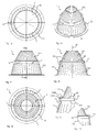
- the in Fig. 1a to 1g shown in different representation light reflector 1. has a reflector shell 10, which defines an interior 100 of the light reflector 1.
- the light reflector 1 is multi-part, formed with two partial circumferential surfaces.
- the light reflector 1 preferably has a round, ellipsoidal and / or polygonal cross section.
- the light reflector 1 has a light-permeable separating disk 20, which is arranged in the interior 100 and separates it for subdivision into a first and a second reflector chamber 101, 102.
- the light reflector 1 is set up in such a way that the light which enters the first reflector chamber 101 passes through the separating disk 20 into the second reflector chamber 102 and exits from the light reflector 1.
- mounting embossments 11 are present.
- the fastening embossings 11 are achieved by local material deformation of the reflector shell 10.
- a substantially conical deformation in the form of a depression on the outside of the reflector outer surface 10 is shown.
- the diffuser or cutting disc 20 is clamped in this material deformation between a plurality of circumferentially distributed attachment points or embossments 11.
- the fastening embossings 11 are, for example, uniformly or non-uniformly distributed along a circumferential point or cross-sectional portion of the light reflector 1.
- a first and a second shell piece 110, 120 are present. These are essentially designed as conical or Paraboloidstumpf which are pushed or nested in each other.
- the first shell piece 110 has an outwardly projecting collar 1100.
- the second shell piece 120 accordingly has an inwardly projecting collar 1200, so that the two shell pieces 110, 120 abut each other after being pushed together.
- One side of a collar also serves as a support for the separating or diffuser disk 20, which is then used in the interior 100.
- the positioned and fixed parts are permanently connected to one another by at least two fastening embossings being formed on the reflector outer surface 10 by material deformation.
- At least one fastening embossment 11 can already be formed in a light reflector 1 manufactured as a prefabricated product.
- the separating or diffuser disk 20 is inserted at an edge location between the collar and the existing fastening embossment 11 and deposited on the collar.
- the step of positioning and fixing takes place, in order subsequently to create one or more fastening embossings 11 by means of at least one further material deformation.
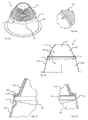
- the in Fig. 2a to 2d shown light reflector 1 has a multi-part reflector outer surface 10, that is, it is formed from two shell parts 110,120.
- the cutting disk 20 is formed in this embodiment as an optical lens.
- the individual parts, that is to say shell pieces 110, 120 and lens 20 are connected to one another in an inventive manner by corresponding fastening embossings 11.
- the lens can be optimally positioned and fixed in the optical axis M of the light reflector.
- the positioning can be carried out, for example, by measuring the light distribution of the light reflector, wherein a positioning stamping 13 is achieved by corresponding application of force in the material deformation at a peripheral location.
- positioning can also take place, for example, by rotating the provisionally fixed parts of the light reflector 1 along the optical axis and determining the appropriate peripheral location for attaching the positioning embossment 13 by detecting an imbalance.
- a lens may, for example, be designed as a concave, plano-concave, convex or plano-convex lens or as a Fresnel lens.
- the partial jacket surfaces of the light reflector 1 according to the embodiment described can be made of plastic in an injection molding or deep-drawing process.
- Each reflector or partial jacket surface can also be produced as a pressed part from a metal sheet, for example aluminum.
- the starting material may be surface treated before or after processing. This can for example be done by hammer blow, steaming or the like.
- the light inlet opening of the light reflector 1 facing the light source and / or in the connection region of the jacket pieces 110, 120 may have a flexible, eg elastic, extensible or resilient element, for example in the form of a collar or a lip.
- the collar serves to bridge tolerances, which may arise, for example, in the production of the light reflector or the reflector attachment, or which may be caused by thermal effects during operation of the light reflector to bridge or compensate.
- the flexible sealing element ensures a light-tight transition between the light source and the light reflector.
- the flexible sealing element thus has an interface function between the light source and the light reflector.
- the reflector outer surface 10 of in Fig. 3a to 3d shown reflector 1 is integrally formed.
- the surface in the interior 100 of the light reflector 1 can, for example, smooth, dull, with longitudinal, transverse, diamond or spherical facets, structured, eg. By hammer blow and combinations these properties are processed, treated or trained.
- a pressure, pressing or joining tool 30, 31 By means of a pressure, pressing or joining tool 30, 31, the mounting embossments 11 and the positioning embossments 13 can be produced efficiently. Not only is the cutting disk 20 fastened in a one-piece light reflector 1, but also a reflector casing 10 formed from a plurality of casing pieces 110, 120 can be realized, which are connected to the separating disk 20 by the same fixing embossings 11.
- a pressure tool 30, 31 may, for example, be a grain which acts in the direction of force F.
- the light reflector 1 can be used for the production of luminaires, the luminous means for irradiating light being arranged in the interior 100 of the light reflector 1.
- the light source may be formed, for example, as a flat LED light source. The areal extent of the light source usually results in an uneven light distribution. Light, which now radiates into the first reflector chamber 101, is mixed in this and passes through the cutting disk 20 in a homogeneous manner in the second reflector chamber 102, from which the light is emitted or reflected to the outside. As a result, the most homogeneous possible light distribution can be achieved.
- the first reflector chamber 101 can also be used to mix individual colored light sources, for example red, green and blue.
- a corresponding method for producing a light reflector 1 with a one-piece or one-piece reflector jacket may comprise the steps of using the separator disk 20 in the interior 100 of the light reflector 1 and by applying force F by means of a joining tool 30, 31 to the reflector jacket 10 at least in places is deformed such that the reflector shell 10 is permanently in contact with the cutting disk 20. If the light reflector 1 is formed from a plurality of jacket pieces 110, 120, these are assembled in advance.
- a plurality of diffuser disks 20 can also be arranged in the interior 100 of a light reflector 1.
- the cutting disc 20 is in a step of prefabrication with a shell piece 110 made of plastic, for example, connected by the fact that the outer edge of the blade is surrounded by plastic.
- the second shell piece 120 would be in contact with the plastic skirt.
- the connection of the jacket pieces by fixing embossments 11 is also applicable in this case.
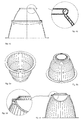
- Fig. 4a and 4b illustrate an embodiment of the light reflector, in which the light inlet opening of the light reflector 1 facing the light source, a flexible, eg. Elastic, stretchable or resilient element 1101, for example.
- a flexible, eg. Elastic, stretchable or resilient element 1101 for example.
- the bead serves to bridge tolerances, which may arise, for example, in the manufacture of the light reflector or the reflector attachment, or which may be caused by thermal effects during operation of the light reflector.
- the bead formed as a flexible sealing element ensures a light-tight transition between the light source and light reflector.
- the flexible sealing element thus has an interface function between the light source and the light reflector.
- any friction between the light source and the reflector is absorbed by the elastic element, so that a material abrasion is prevented.
- the in Fig. 5a to 5d shown light reflector 1 is formed from a shell piece.
- the cutting disk 20 in the interior 100 of the light reflector 1 is formed as a diffuser hood and has an at least partially spherical portion. It is secured by at least one, here preferably three, integrally formed on the reflector shell 10 mounting embossments 11 on the jacket piece of the light reflector 1.
- the in Fig. 6 reflector shown has a one-piece reflector shell with two circumferential, outwardly directed beads in which two plano-convex lenses are held with facing flat surfaces.
- the in Fig. 7a and 7b shown reflector has a multi-part reflector shell and two as in the Fig. 6 shown reflector arranged lenses, wherein the edge of the lenses and the flange-shaped collar of the respective overlying skirt portion is covered by an annular elastic member and is held together. This element allows more reliable protection of the lenses from damage and better compensation of thermal expansion.
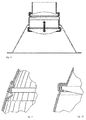
- the in Fig. 8 reflector shown has a multi-part reflector shell whose lower shell portion 120 is cylindrical in its upper region. At the upper edge, as already described, it possesses an inwardly directed collar under which an outwardly directed flange-shaped collar of the upper shell part 110 and a first lens-shaped diffuser are held. Inside the cylindrical part of a cylindrical sleeve is arranged vertically displaceable, the lower Edge includes a second lens. With this arrangement, the desired illumination can be optimized and possibly fixed by an impression.
- FIG. 9 illustrates a further embodiment of the light reflector in a detailed view. It is conceivable that the reflector shell 10, or the shell pieces 110, 120 have no collar.
- the jacket pieces 110, 120 are dimensioned so that the individual parts can be inserted into each other first, so that they overlap in places, then connected by several embossments 11 both above, as well as below the respective edge of the separation or diffuser disc 20 to become.
- the overlapping area should be selected at least by the thickness of the cutting disk 20 and an embossing area.
- FIG. 10 shows another possible attachment variant for a lenticular diffuser.
- a lower shell portion 120 has at its upper edge an inwardly directed collar 1200.
- An upper shell portion 110 is provided at its lower edge with a rim of a lenticular diffuser embracing flanging 1100, which in turn is held by impressions 11 in the lower shell part.
Landscapes
- Engineering & Computer Science (AREA)
- General Engineering & Computer Science (AREA)
- Securing Globes, Refractors, Reflectors Or The Like (AREA)
Description
- Die Erfindung betrifft einen Lichtreflektor gemäss dem Oberbegriff des unabhängigen Patentanspruchs 1 und ein entsprechendes Herstellungsverfahren.
- Aus dem Stand der Technik sind Lichtreflektoren, insbesondere für Leuchten, allgemein bekannt. Sie dienen dem Verteilen von Licht, welches von einem oder mehreren Leuchtmitteln einer Leuchte ausgestrahlt wird. Mittels des Lichtreflektors kann die Lichtverteilung der Leuchte eingestellt werden.
- Lichtreflektoren weisen wenigstens stellenweise reflektierende Flächen auf. Bei Lichtreflektoren mit im Wesentlichen polygonalen Innenquerschnittsabschnitten werden üblicherweise punktförmige Lichtquellen verwendet, welche vorzugsweise in der Mittelachse oder optischen Achse des Lichtreflektors angeordnet sind. Nach dem Reflexionsgesetz wird bei einem Lichtreflektor mit bspw. runden Querschnittsabschnitten, also etwa bei im Wesentlichen rotationssymmetrischem Aufbau des Lichtreflektors, eine gleichförmige Lichtverteilungskurve erzielt.
- Ist die Lichtquelle jedoch flächig ausgebildet und weist bspw. eine rechteckige oder eine andere nicht kreisrunde Grundform auf, so wird die Lichtverteilungskurve ihre Gleichförmigkeit verlieren. Um dies zu verhindern, wird im Stand der Technik eine Lichtmischkammer vorgeschlagen, welche mittels einer vorzugsweise diffusen, mindestens teilweise lichtdurchlässigen Scheibe gebildet wird, indem diese in einem Querschnittsabschnitt des Lichtreflektors angeordnet ist.
- Zwischen der Lichtquelle bzw. der Lichteintrittsöffnung des Lichtreflektors und der Scheibe wird das eintreffende Licht "gemischt", bevor es ungefähr gleichmässig durch die Scheibe hindurch zur Lichtaustrittsöffnung des Lichtreflektors austritt und an die Umgebung abgegeben wird. Hierdurch kann eine gleichförmige Lichtverteilung erzielt werden.
- Im Stand der Technik ist die Befestigung einer Diffusor- oder Trennscheibe im Inneren des Lichtreflektors derart gelöst, dass die Herstellung solcher Lichtreflektoren aufwändig und kostenintensiv ist.
-
US 3037110 A1 ,DE 3238876 A1 undUS 2010/0165635 A1 offenbaren Lichtreflektoren des Standes der Technik. - Ein anderer Nachteil der bekannten Lichtreflektoren besteht darin, dass die Trennscheibe derart am Reflektor montiert ist, dass im Betrieb störende Geräusche entstehen, etwa, weil die Befestigung der Scheibe durch die Wärmeeinwirkung teilweise gelöst worden ist.
- Es ist daher Aufgabe der vorliegenden Erfindung, einen Lichtreflektor vorzuschlagen, welcher die Nachteile des Stands der Technik nicht aufweist. Insbesondere ist es eine Aufgabe der Erfindung, die Herstellung des Lichtreflektors kosteneffektiv zu gestalten sowie einen geräuschlosen Betrieb sicherzustellen. Zudem soll eine Lichtverteilungskurve eines entsprechenden Lichtreflektors nach bestimmten Anforderungen konfigurierbar sein. Im Übrigen soll die Lichtmischkammer des Lichtreflektors bedürfnisorientiert herstellbar sein.
- Die vorliegende Aufgabe wird gelöst durch einen Lichtreflektor gemäss dem unabhängigen Anspruch 1.
- Einer der Vorteile der Erfindung besteht darin, dass die Trennscheibe des Lichtreflektors ohne zusätzliche Befestigungsmittel kosteneffektiv montierbar ist, wobei die Trennscheibe fest im Innenraum des Lichtreflektors gehalten ist. Durch die bewegungsfreie Montage der Trennscheibe wird ein geräuschloser Betrieb gewährleistet.
- Durch ein entsprechendes Herstellungsverfahren können zudem mehrere Mantelstücke der Reflektormantelfläche des Lichtreflektors miteinander verbunden werden.
- Weitere die Erfindung verbessernde Massnahmen werden nachstehend gemeinsam mit der Beschreibung eines bevorzugten Ausführungsbeispiels der Erfindung anhand der Figuren sowie anhand der abhängigen Ansprüche näher dargestellt.
-
Fig. 1a bis 1g zeigen eine erste Ausführungsform des Lichtreflektors; -
Fig. 2a bis 2d zeigen eine weitere Ausführungsform des Lichtreflektors; -
Fig. 3a bis 3c zeigen eine andere Ausführungsform des Lichtreflektors. -
Fig. 4a und 4b zeigen eine Ausführungsform mit einer plan-konvexen Linse als Diffusor. -
Fig. 5a bis 5d zeigen eine Ausführungsform mit einem sphärisch gewölbten Diffusor. -
Fig. 6 zeigt eine Ausführungsform mit zwei plan-konvexen Linsen als Diffusor -
Fig. 7a und 7b zeigen eine Ausführungsform eines mehrteiligen Reflektors mit zwei plan-konvexen Linsen und elastischen Halte- und Dämpfungselementen. -
Fig. 8 zeigt eine Ausführungsform mit mehreren Diffusoren, von denen ein linsenförmiger höhenverstellbar ist. -
Fig. 9 zeigt eine Ausführungsform eines mehrteiligen Reflektors, bei dem der Diffusor im oberen Mantelteil gehalten ist. -
Fig. 10 zeigt eine Ausführungsform der Diffusor vom unteren Rand des oberen Mantelteils umfasst und gehalten ist. - Der in
Fig. 1a bis 1g in unterschiedlicher Darstellung gezeigte Lichtreflektor 1. weist einen Reflektormantel 10 auf, welcher einen Innenraum 100 des Lichtreflektors 1 definiert. Der Lichtreflektor 1 ist mehrteilig, mit zwei Teilmantelflächen ausgebildet. Der Lichtreflektor 1 weist vorzugsweise einen runden, ellipsoiden und/oder polygonalen Querschnitt auf. Der Lichtreflektor 1 weist eine lichtdurchlässige Trennscheibe 20 auf, welche im Innenraum 100 angeordnet ist und diesen zur Unterteilung in eine erste und eine zweite Reflektorkammer 101,102 trennt. - Der Lichtreflektor 1 ist derart eingerichtet, dass das Licht, welches in die erste Reflektorkammer 101 eintritt, durch die Trennscheibe 20 hindurch in die zweite Reflektorkammer 102 ein- und von dieser aus dem Lichtreflektor 1 austritt. Zur unbeweglichen Befestigung der Trennscheibe 20 im Innenraum 100 des Lichtreflektors 1 sind mehrere am Reflektormantel 10 angeformte Befestigungsprägungen 11 vorhanden.
- Die Befestigungsprägungen 11 werden durch stellenweise Materialdeformation des Reflektormantels 10 erzielt. Vorliegend ist eine im Wesentlichen kegelförmige Deformation in Form einer Vertiefung an der Aussenseite der Reflektormantelfläche 10 dargestellt. Durch Verformen des Materials der Reflektormantelfläche 10 bewirkt die Vertiefung an der Innenseite der Reflektormantelfläche 10 eine stellenweise Erhebung. Die Diffusor- oder Trennscheibe 20 wird bei dieser Materialdeformation zwischen mehreren entlang des Umfangs verteilten Befestigungspunkten oder -prägungen 11 eingeklemmt. Die Befestigungsprägungen 11 sind bspw. gleichmässig oder ungleichmässig entlang einer Umfangsstelle bzw. Querschnittsabschnitts des Lichtreflektors 1 verteilt.
- Bei der Herstellung einer Ausführungsform eines Lichtreflektors 1 gemäss
Fig. 1 , sind wie dargestellt ein erstes und ein zweites Mantelstück 110,120 vorhanden. Diese sind im Wesentlichen als Kegel- oder Paraboloidstumpf ausgebildet, welche in einander geschoben oder verschachtelt sind. Vorteilhafterweise weist das erste Mantelstück 110 einen nach aussen ragenden Kragen 1100 auf. Das zweite Mantelstück 120 weist entsprechend einen nach innen ragenden Kragen 1200 auf, so dass die beiden Mantelstücke 110,120 nach dem Zusammenschieben aneinander anliegen. Eine Seite des einen Kragens dient zugleich als Auflage für die Trenn- oder Diffusorscheibe 20, welche anschliessend im Innenraum 100 eingesetzt wird. Durch geeignete Fixation der Trennscheibe 20 im Innenraum des Lichtreflektors 1 wird die optimale Positionierung der Trennscheibe 20 sowie der beiden Mantelstücke 110,120 des Lichtreflektors 1 bezüglich der optischen Achse M des Lichtreflektors erreicht. - Die positionierten und fixierten Teile werden in einem weiteren Schritt dadurch miteinander dauerhaft verbunden, dass durch Materialdeformation mindestens zwei Befestigungsprägungen an die Reflektormantelfläche 10 angeformt werden.
- Mindestens eine Befestigungsprägung 11 kann bereits in einem als Vorfabrikat hergestellten Lichtreflektor 1 angeformt sein. In diesem Fall wird die Trenn- oder Diffusorscheibe 20 an einer Randstelle zwischen Kragen und vorhandener Befestigungsprägung 11 eingeschoben und auf den Kragen abgelegt. Hiernach erfolgt der Schritt der Positionierung und Fixierung, um anschliessend durch mindestens eine weitere Materialdeformation eine oder mehrere Befestigungsprägungen 11 zu erstellen. Ein Vorteil dieses Verfahrens besteht in der Handhabung der einzelnen Bestandteile beim Zusammensetzten.
- Der in
Fig. 2a bis 2d gezeigte Lichtreflektor 1, besitzt eine mehrteilige Reflektormantelfläche 10, d.h. sie ist aus zwei Mantelteilen 110,120 gebildet. Die Trennscheibe 20 ist in diesem Ausführungsbeispiel als optische Linse ausgebildet. Die einzelnen Teile, also Mantelstücke 110,120 und Linse 20 sind auf erfinderische Weise durch entsprechende Befestigungsprägungen 11 dauerhaft miteinander verbunden. Mittels einer oder mehreren Positionierprägungen 13 kann bei der Herstellung des Lichtreflektors 1 die Linse optimal in der optischen Achse M des Lichtreflektors positioniert und fixiert werden. - Die Positionierung kann bspw. durch Messung der Lichtverteilung des Lichtreflektors erfolgen, wobei durch entsprechende Krafteinwirkung bei der Materialdeformation an einer Umfangsstelle eine Positionierprägung 13 erzielt wird.
- Eine Positionierung kann aber bspw. auch dadurch erfolgen, indem die provisorisch zusammen fixierten Teile des Lichtreflektors 1 entlang der optischen Achse rotiert werden und durch Feststellen einer Unwucht die geeignete Umfangsstelle zum Anbringen der Positionierprägung 13 ermittelt wird.
- Eine Linse kann bspw. als konkave, plan-konkave, konvexe oder plan-konvexe Linse oder als Fresnel-Linse ausgebildet sein.
- Die Teilmantelflächen des Lichtreflektors 1 gemäss der beschriebenen Ausführungsform können aus Kunststoff in einem Spritzgiess- oder Tiefziehverfahren hergestellt werden. Jede Reflektor- bzw. Teilmantelfläche kann auch als Drückteil aus einem Blech, bspw. Aluminium, hergestellt sein. Das Ausgangsmaterial kann vor oder nach der Verarbeitung oberflächenbehandelt sein bzw. werden. Dies kann bspw. durch Hammerschlag, Bedampfung oder dergleichen mehr erfolgen.
- In einer Ausführungsform des Lichtreflektors kann die der Lichtquelle zugewandte Lichteintrittsöffnung des Lichtreflektors 1 und/oder im Verbindungsbereich der Mantelstücke 110,120 ein flexibles, bspw. elastisches, dehnbares oder federndes Element, bspw. in Form eines Kragens oder einer Lippe aufweisen. Der Kragen dient dabei zur Überbrückung von Toleranzen, welche bspw. bei der Herstellung des Lichtreflektors oder der Reflektorbefestigung entstehen können, oder welche durch thermische Einwirkungen im Betrieb des Lichtreflektors entstehen können, zu überbrücken bzw. auszugleichen. Das flexible Dichtelement gewährleistet dabei einen lichtdichten Übergang zwischen Lichtquelle und Lichtreflektor. Das flexible Dichtelement hat somit Schnittstellenfunktion zwischen Lichtquelle und Lichtreflektor.
- Die Reflektormantelfläche 10 des in
Fig. 3a bis 3d gezeigten Reflektors 1 ist einteilig ausgebildet. Die Oberfläche im Innenraum 100 des Lichtreflektors 1 kann bspw. glatt, matt, mit Längs-, Quer-, Diamant- oder Kugelfacetten, strukturiert, bspw. durch Hammerschlag sowie Kombinationen dieser Eigenschaften bearbeitet, behandelt oder ausgebildet sein. - Mittels eines Druck-, Press- oder Fügewerkzeugs 30, 31 sind die Befestigungsprägungen 11 sowie die Positionierprägungen 13 rationell herstellbar. Es ist dabei nicht nur die Trennscheibe 20 in einem einteilig ausgebildeten Lichtreflektor 1 befestigbar, sondern es ist auch ein aus mehreren Mantelstücken 110,120 gebildeter Reflektormantel 10 realisierbar, welche durch dieselben Befestigungsprägungen 11 mit der Trennscheibe 20 verbunden werden. Ein Druckwerkzeug 30,31 kann bspw. ein Körner sein, welcher in Kraftrichtung F wirkt.
- Der erfindungsgemässe Lichtreflektor 1 kann zur Herstellung von Leuchten verwendet werden, wobei das Leuchtmittel zum Einstrahlen von Licht in den Innenraum 100 des Lichtreflektors 1 angeordnet ist. Das Leuchtmittel kann bspw. als flächiges LED-Leuchtmittel ausgebildet sein. Die flächige Ausdehnung der Lichtquelle hat üblicherweise eine ungleiche Lichtverteilung zur Folge. Licht, welches nun in die erste Reflektorkammer 101 einstrahlt, wird in dieser gemischt und tritt durch die Trennscheibe 20 in homogener Weise in die zweite Reflektorkammer 102 über, von welcher aus das Licht nach aussen abgegeben bzw. reflektiert wird. Dadurch kann eine möglichst homogene Lichtverteilung erzielt werden. Die erste Reflektorkammer 101 kann auch zur Mischung von farbigen Einzellichtquellen, bspw. rot, grün und blau verwendet werden.
- Ein entsprechendes Verfahren zur Herstellung eines Lichtreflektors 1 mit einem einstückigen oder einteiligen Reflektormantel kann die Schritte umfassen, dass die Trennscheibe 20 im Innenraum 100 des Lichtreflektors 1 eingesetzt wird und dass durch Krafteinwirkung F mittels eines Fügewerkzeugs 30,31 der Reflektormantel 10 mindestens stellenweise derart deformiert wird, dass der Reflektormantel 10 mit der Trennscheibe 20 dauerhaft in Kontakt steht. Wird der Lichtreflektor 1 aus mehreren Mantelstücken 110,120 gebildet, so werden diese vorab zusammengesteckt.
- Auf die beschriebene Weise können im Innenraum 100 eines Lichtreflektors 1 auch mehrere Diffusorscheiben 20 angeordnet sein.
- Gemäss einer weiteren Ausführungsform des Lichtreflektors 1 wird die Trennscheibe 20 in einem Schritt der Vorfabrikation mit einem aus Kunststoff hergestellten Mantelstück 110 bspw. dadurch verbunden, dass der äussere Rand der Trennscheibe von Kunststoff eingefasst wird. In den Ausführungsformen gemäss den
Figuren 1a und2a würde das zweite Mantelstück 120 mit der Kunststoffeinfassung in Kontakt stehen. Die Verbindung der Mantelstücke durch Befestigungsprägungen 11 ist jedoch auch in diesem Fall anwendbar. -
Fig. 4a und 4b illustrieren eine Ausführungsform des Lichtreflektors, bei welcher die der Lichtquelle zugewandte Lichteintrittsöffnung des Lichtreflektors 1 ein flexibles, bspw. elastisches, dehnbares oder federndes Element 1101, bspw. in Form eines Kragens, einer Lippe oder Wulst aufweisen. Der Wulst dient dabei zur Überbrückung von Toleranzen, welche bspw. bei der Herstellung des Lichtreflektors oder der Reflektorbefestigung entstehen können, oder welche durch thermische Einwirkungen im Betrieb des Lichtreflektors entstehen können. Das als Wulst ausgebildete flexible Dichtelement gewährleistet dabei einen lichtdichten Übergang zwischen Lichtquelle und Lichtreflektor. Das flexible Dichtelement hat somit Schnittstellenfunktion zwischen Lichtquelle und Lichtreflektor. Im Weiteren wird allfällige Reibung zwischen Lichtquelle und Reflektor durch das elastische Element absorbiert, so dass ein Materialabrieb verhindert wird. - Der in
Fig. 5a bis 5d gezeigte Lichtreflektor 1, ist wiederum aus einem Mantelstück gebildet. Die Trennscheibe 20 im Innenraum 100 des Lichtreflektors 1 ist als Diffusorhaube ausgebildet und weist einen mindestens teilweise kugelförmigen Abschnitt auf. Sie ist durch mindestens eine, hier vorzugsweise drei, am Reflektormantel 10 angeformte Befestigungsprägungen 11 am Mantelstück des Lichtreflektors 1 befestigt. - Der in
Fig. 6 dargestellte Reflektor besitzt eine einstückigen Reflektormantel mit zwei umlaufenden, nach aussen gerichteten Sicken in denen zwei plan-konvexe Linsen mit einander zugewandten planen Flächen gehalten sind. Durch diese Ausführungsform wird eine noch effektivere Lichtmischung erreicht. - Der in
Fig. 7a und 7b gezeigte Reflektor besitzt eine mehrteiligen Reflektormantel und zwei wie bei dem inFig. 6 gezeigten Reflektor angeordnete Linsen, wobei der Rand der Linsen und der flanschförmige Kragen des jeweils darüber liegenden Mantelteils von einem ringförmigen elastischen Element umfasst ist und zusammengehalten wird. Durch dieses Element wird ein zuverlässigerer Schutz der Linsen vor Beschädigung und eine bessere Kompensation von Wärmeausdehnungen möglich. - Der in
Fig. 8 dargestellte Reflektor besitzt einen mehrteiligen Reflektormantel, dessen unterer Mantelteil 120 in seinem oberen Bereich zylindrisch ausgebildet ist. Am oberen Rand besitzt er wie bereits beschriebene Formen einen nach innen gerichteten Kragen, unter dem ein nach aussen gerichteter flanschförmiger Kragen des oberen Mantelteils 110 und ein erster linsenförmiger Diffusor gehalten ist. Im Inneren des zylindrischen Teils ist eine zylindrische Büchse vertikal verschiebbar angeordnet, deren unterer Rand eine zweite Linse umfasst. Mit dieser Anordnung kann die gewünschte Ausleuchtung optimiert werden und ggf. durch eine Einprägung fixiert werden. -
Figur 9 illustriert eine weitere Ausführungsform des Lichtreflektors in einer Detailansicht. Es ist vorstellbar, dass der Reflektormantel 10, bzw. die Mantelstücke 110, 120 keinen Kragen aufweisen. Die Mantelstücke 110, 120 sind dabei so dimensioniert, dass die einzelnen Teile zuerst ineinander gesteckt werden können, so dass sie sich stellenweise überlappen, um anschliessend durch mehrere Prägungen 11 sowohl oberhalb, wie auch unterhalb des jeweiligen Rands der Trenn- oder Diffusorscheibe 20 miteinander verbunden zu werden. Der Überlappungsbereich sollte dabei mindestens um Dicke der Trennscheibe 20 und einem Bereich zur Prägung gewählt werden. - Die Detaildarstellung der
Fig. 10 zeigt eine weitere mögliche Befestigungsvariante für einen linsenförmigen Diffusor. Ein unterer Mantelteil 120 besitzt an seinem oberen Rand eine nach innen gerichteten Kragen 1200. Ein oberer Mantelteil 110 ist an seinem unteren Rand mit einer den Rand eines linsenförmigen Diffusors umgreifenden Bördelung 1100 versehen, die wiederum durch Einprägungen 11 im unteren Mantelteil gehalten wird.
Claims (12)
- Lichtreflektor (1), mit einem Reflektormantel (10), welcher einen Innenraum (100) des Lichtreflektors (1) definiert, mit mindestens einer lichtdurchlässigen Trennscheibe (20), welche im Innenraum (100) angeordnet ist und diesen in mehrere Reflektorkammern (101,102) trennt, dadurch gekennzeichnet, dass die Trennscheibe (20) im Innenraum (100) des Lichtreflektors (1) durch mindestens eine am Reflektormantel (10) angeformte Befestigungsprägung (11) als eine im Wesentlichen kegelförmige Deformation in Form einer Vertiefung an einer Aussenseite des Reflektormantels (10) befestigt ist.
- Lichtreflektor (1) gemäss Anspruch 1, dadurch gekennzeichnet, dass der Lichtreflektor rotationssymmetrisch ausgebildet ist und eine Mittelachse (M) aufweist, wobei die Trennscheibe (20) durch mindestens eine am Reflektormantel (10) angeformte Positionierprägung (13) bezüglich der Mittelachse (M) beim Prägenvorgang positionierbar ist.
- Lichtreflektor (1) gemäss einem der Ansprüche 1 oder 2, dadurch gekennzeichnet, dass der Lichtreflektor (1) eine erste Reflektorkammer (101) aufweist, in welche Licht eintritt und durch die Trennscheibe (20) hindurch in eine zweite Reflektorkammer (102) ein- und von dieser aus dem Lichtreflektor (1) austritt.
- Lichtreflektor (1) gemäss einem der vorgenannten Ansprüche, dadurch gekennzeichnet, dass der Reflektormantel (10) in einem Drückverfahren oder in ein Spritzgiessverfahren oder in einem Tiefziehverfahren hergestellt ist.
- Lichtreflektor (1) gemäss einem der vorgenannten Ansprüche, dadurch gekennzeichnet, dass die bzw. jede Prägung (11,13) in einem Drückverfahren hergestellt ist.
- Lichtreflektor (1) gemäss einem der vorgenannten Ansprüche, dadurch gekennzeichnet, dass der Reflektormantel (10) mindestens teilweise aus einem Metall- oder Leichtmetallblech hergestellt ist.
- Lichtreflektor (1) gemäss einem der vorgenannten Ansprüche, dadurch gekennzeichnet, dass der Reflektormantel (10) teilweise aus thermoplastisch verformbarem Kunststoff hergestellt ist.
- Lichtreflektor (1) gemäss einem der vorgenannten Ansprüche, dadurch gekennzeichnet, dass die Trennscheibe (20) eine dem Lichteintritt zugwandte matt ausgebildete Seite (201) und/oder eine dem Lichtaustritt zugewandte glänzend ausgebildete Seite (202) aufweist.
- Lichtreflektor (1) gemäss einem der vorgenannten Ansprüche, dadurch gekennzeichnet, dass der Reflektormantel (10) aus einem ersten Mantelstück (110) und einem mit diesem verbindbaren zweiten Mantelstück (120) besteht.
- Lichtreflektor (1) gemäss Anspruch 9, dadurch gekennzeichnet, dass mindestens eines der Mantelstücke (110,120) mit der Trennscheibe (20) in Kontakt steht und durch mindestens eine an einem der Mantelstücke (110,120) angeformten Befestigungsprägung (11) miteinander verbunden sind.
- Leuchte mit einem Leuchtmittel sowie mit einem Lichtreflektor (1) gemäss einem der vorgenannten Ansprüche, wobei das Leuchtmittel zum Einstrahlen von Licht in den Innenraum (100) des Lichtreflektors (1) angeordnet ist.
- Verfahren zur Herstellung eines Lichtreflektors (1) gemäss einem der Ansprüche 1 bis 10, dadurch gekennzeichnet, dass die Trennscheibe (20) im Innenraum (100) des Lichtreflektors (1) eingesetzt wird und dass durch Krafteinwirkung mittels eines Fügewerkzeugs (30,31) der Reflektormantel (10) mindestens stellenweise derart deformiert wird, dass der Reflektormantel (10) mit der Trennscheibe (20) dauerhaft in Kontakt steht.
Applications Claiming Priority (1)
| Application Number | Priority Date | Filing Date | Title |
|---|---|---|---|
| CH01443/11A CH705537A1 (de) | 2011-09-02 | 2011-09-02 | Reflektor mit Reflektorkammer. |
Publications (2)
| Publication Number | Publication Date |
|---|---|
| EP2565529A1 EP2565529A1 (de) | 2013-03-06 |
| EP2565529B1 true EP2565529B1 (de) | 2016-08-17 |
Family
ID=46799105
Family Applications (1)
| Application Number | Title | Priority Date | Filing Date |
|---|---|---|---|
| EP12182587.1A Active EP2565529B1 (de) | 2011-09-02 | 2012-08-31 | Reflektor mit Reflektorkammer |
Country Status (2)
| Country | Link |
|---|---|
| EP (1) | EP2565529B1 (de) |
| CH (1) | CH705537A1 (de) |
Cited By (1)
| Publication number | Priority date | Publication date | Assignee | Title |
|---|---|---|---|---|
| EP2871411B1 (de) | 2013-11-06 | 2016-08-31 | Zumtobel Lighting GmbH | Optisches Element für eine Leuchte, sowie Leuchte |
Families Citing this family (3)
| Publication number | Priority date | Publication date | Assignee | Title |
|---|---|---|---|---|
| US20160169477A9 (en) * | 2014-03-30 | 2016-06-16 | Khatod Optoelectronics Srl | Reflector for a led light source and related led lighting device |
| EP3249287B1 (de) * | 2016-05-25 | 2019-03-27 | OSRAM GmbH | Reflektor für beleuchtungsvorrichtungen, zugehörige vorrichtung und verfahren |
| CN111045196B (zh) * | 2020-01-02 | 2024-12-13 | 东莞市美光达光学科技有限公司 | 一种大视场、高像素光学系统及采用该光学系统的手机摄像头模组 |
Family Cites Families (4)
| Publication number | Priority date | Publication date | Assignee | Title |
|---|---|---|---|---|
| US3037110A (en) * | 1958-05-06 | 1962-05-29 | Centnry Lighting Inc | Downlight and device for varying the spectral quality thereof |
| DE3238876C2 (de) * | 1982-10-18 | 1985-01-17 | Franz Sill Gmbh, 1000 Berlin | Reflektor für eine mit einer Hochdruckentladungslampe versehene Decken-Einbauleuchte |
| EP0750159A3 (de) * | 1995-06-22 | 1997-05-02 | Hans J Schmitz | Einbauleuchte |
| US20100165635A1 (en) * | 2008-12-29 | 2010-07-01 | Fu Zhun Precision Industry (Shen Zhen) Co., Ltd. | Led unit |
-
2011
- 2011-09-02 CH CH01443/11A patent/CH705537A1/de not_active Application Discontinuation
-
2012
- 2012-08-31 EP EP12182587.1A patent/EP2565529B1/de active Active
Cited By (2)
| Publication number | Priority date | Publication date | Assignee | Title |
|---|---|---|---|---|
| EP2871411B1 (de) | 2013-11-06 | 2016-08-31 | Zumtobel Lighting GmbH | Optisches Element für eine Leuchte, sowie Leuchte |
| EP2871411B2 (de) † | 2013-11-06 | 2021-07-07 | Zumtobel Lighting GmbH | Optisches Element für eine Leuchte, sowie Leuchte |
Also Published As
| Publication number | Publication date |
|---|---|
| EP2565529A1 (de) | 2013-03-06 |
| CH705537A1 (de) | 2013-03-15 |
Similar Documents
| Publication | Publication Date | Title |
|---|---|---|
| EP3312501B1 (de) | Beleuchtungsvorrichtung für fahrzeuge | |
| DE102007035528B4 (de) | Leuchte | |
| DE102007035396B4 (de) | Leuchte | |
| DE10249113B4 (de) | Fahrzeugleuchte, insbesondere Heckleuchte, vorzugsweise für Kraftfahrzeuge | |
| EP2565529A1 (de) | Reflektor mit Reflektorkammer | |
| EP1574779B1 (de) | Rückstrahler für Heckleuchten von Fahrzeugen, vorzugsweise von Kraftfahrzeugen | |
| DE3239754C2 (de) | ||
| DE102014212918A1 (de) | Kraftfahrzeug-Beleuchtungseinrichtung | |
| DE60303770T2 (de) | Verfahren zur Herstellung von einer Beleuchtungs- oder Signaleinrichtung, und eine durch dieses Verfahren hergestellte Beleuchtungs- oder Signaleinrichtung | |
| EP3023689B1 (de) | Leuchtvorrichtung | |
| DE102013112849A1 (de) | Leuchten-Reflektor | |
| DE102017000805A1 (de) | Kraftfahrzeugleuchte sowie Kraftfahrzeug | |
| DE10241023A1 (de) | Leuchte für Fahrzeuge, insbesondere Heckleuchte für Kraftfahrzeuge | |
| EP1726872A3 (de) | Elektrische Leuchte | |
| DE202007015488U1 (de) | Leuchte | |
| DE102012110231A1 (de) | Lichteinkoppelvorrichtung für einen Lichtleiter | |
| DE102014117314A1 (de) | Beleuchtungsvorrichtung für Fahrzeuge | |
| EP1072840B1 (de) | Leuchte | |
| DE102015219117A1 (de) | Leuchtenoptik | |
| EP3045803A1 (de) | Leuchte | |
| EP2650602A2 (de) | Leuchte mit LEDs und Kollimator-Linsen | |
| EP2019255A2 (de) | Leuchte zur Ausleuchtung einer Fläche in einem Gebäude | |
| EP1628071B1 (de) | Leuchteinheit für Kraftfahrzeuge | |
| DE102013009848B4 (de) | Vorrichtung zur Lagesicherung und Befestigung einer kreisförmigen Abdeck- oder Streuscheibe in einem kreisringförmigen Halteteil, insbesondere für Leuchtenkörper | |
| DE102008063370A1 (de) | Leuchte |
Legal Events
| Date | Code | Title | Description |
|---|---|---|---|
| PUAI | Public reference made under article 153(3) epc to a published international application that has entered the european phase |
Free format text: ORIGINAL CODE: 0009012 |
|
| AK | Designated contracting states |
Kind code of ref document: A1 Designated state(s): AL AT BE BG CH CY CZ DE DK EE ES FI FR GB GR HR HU IE IS IT LI LT LU LV MC MK MT NL NO PL PT RO RS SE SI SK SM TR |
|
| AX | Request for extension of the european patent |
Extension state: BA ME |
|
| 17P | Request for examination filed |
Effective date: 20130906 |
|
| RBV | Designated contracting states (corrected) |
Designated state(s): AL AT BE BG CH CY CZ DE DK EE ES FI FR GB GR HR HU IE IS IT LI LT LU LV MC MK MT NL NO PL PT RO RS SE SI SK SM TR |
|
| 17Q | First examination report despatched |
Effective date: 20150122 |
|
| GRAP | Despatch of communication of intention to grant a patent |
Free format text: ORIGINAL CODE: EPIDOSNIGR1 |
|
| RIC1 | Information provided on ipc code assigned before grant |
Ipc: F21V 13/04 20060101ALI20160229BHEP Ipc: F21V 5/04 20060101ALN20160229BHEP Ipc: F21V 7/22 20060101ALN20160229BHEP Ipc: F21V 7/00 20060101AFI20160229BHEP Ipc: F21V 7/10 20060101ALN20160229BHEP Ipc: F21V 13/10 20060101ALI20160229BHEP |
|
| INTG | Intention to grant announced |
Effective date: 20160407 |
|
| GRAS | Grant fee paid |
Free format text: ORIGINAL CODE: EPIDOSNIGR3 |
|
| GRAA | (expected) grant |
Free format text: ORIGINAL CODE: 0009210 |
|
| AK | Designated contracting states |
Kind code of ref document: B1 Designated state(s): AL AT BE BG CH CY CZ DE DK EE ES FI FR GB GR HR HU IE IS IT LI LT LU LV MC MK MT NL NO PL PT RO RS SE SI SK SM TR |
|
| REG | Reference to a national code |
Ref country code: GB Ref legal event code: FG4D Free format text: NOT ENGLISH |
|
| REG | Reference to a national code |
Ref country code: CH Ref legal event code: EP |
|
| REG | Reference to a national code |
Ref country code: IE Ref legal event code: FG4D Free format text: LANGUAGE OF EP DOCUMENT: GERMAN |
|
| REG | Reference to a national code |
Ref country code: AT Ref legal event code: REF Ref document number: 821465 Country of ref document: AT Kind code of ref document: T Effective date: 20160915 |
|
| REG | Reference to a national code |
Ref country code: DE Ref legal event code: R096 Ref document number: 502012007955 Country of ref document: DE |
|
| REG | Reference to a national code |
Ref country code: CH Ref legal event code: NV Representative=s name: BRAUNPAT BRAUN EDER AG, CH |
|
| REG | Reference to a national code |
Ref country code: FR Ref legal event code: PLFP Year of fee payment: 5 |
|
| REG | Reference to a national code |
Ref country code: NL Ref legal event code: MP Effective date: 20160817 |
|
| REG | Reference to a national code |
Ref country code: LT Ref legal event code: MG4D |
|
| PG25 | Lapsed in a contracting state [announced via postgrant information from national office to epo] |
Ref country code: HR Free format text: LAPSE BECAUSE OF FAILURE TO SUBMIT A TRANSLATION OF THE DESCRIPTION OR TO PAY THE FEE WITHIN THE PRESCRIBED TIME-LIMIT Effective date: 20160817 Ref country code: NO Free format text: LAPSE BECAUSE OF FAILURE TO SUBMIT A TRANSLATION OF THE DESCRIPTION OR TO PAY THE FEE WITHIN THE PRESCRIBED TIME-LIMIT Effective date: 20161117 Ref country code: RS Free format text: LAPSE BECAUSE OF FAILURE TO SUBMIT A TRANSLATION OF THE DESCRIPTION OR TO PAY THE FEE WITHIN THE PRESCRIBED TIME-LIMIT Effective date: 20160817 Ref country code: NL Free format text: LAPSE BECAUSE OF FAILURE TO SUBMIT A TRANSLATION OF THE DESCRIPTION OR TO PAY THE FEE WITHIN THE PRESCRIBED TIME-LIMIT Effective date: 20160817 Ref country code: LT Free format text: LAPSE BECAUSE OF FAILURE TO SUBMIT A TRANSLATION OF THE DESCRIPTION OR TO PAY THE FEE WITHIN THE PRESCRIBED TIME-LIMIT Effective date: 20160817 Ref country code: IT Free format text: LAPSE BECAUSE OF FAILURE TO SUBMIT A TRANSLATION OF THE DESCRIPTION OR TO PAY THE FEE WITHIN THE PRESCRIBED TIME-LIMIT Effective date: 20160817 Ref country code: FI Free format text: LAPSE BECAUSE OF FAILURE TO SUBMIT A TRANSLATION OF THE DESCRIPTION OR TO PAY THE FEE WITHIN THE PRESCRIBED TIME-LIMIT Effective date: 20160817 |
|
| PG25 | Lapsed in a contracting state [announced via postgrant information from national office to epo] |
Ref country code: BE Free format text: LAPSE BECAUSE OF NON-PAYMENT OF DUE FEES Effective date: 20160831 Ref country code: ES Free format text: LAPSE BECAUSE OF FAILURE TO SUBMIT A TRANSLATION OF THE DESCRIPTION OR TO PAY THE FEE WITHIN THE PRESCRIBED TIME-LIMIT Effective date: 20160817 Ref country code: PT Free format text: LAPSE BECAUSE OF FAILURE TO SUBMIT A TRANSLATION OF THE DESCRIPTION OR TO PAY THE FEE WITHIN THE PRESCRIBED TIME-LIMIT Effective date: 20161219 Ref country code: LV Free format text: LAPSE BECAUSE OF FAILURE TO SUBMIT A TRANSLATION OF THE DESCRIPTION OR TO PAY THE FEE WITHIN THE PRESCRIBED TIME-LIMIT Effective date: 20160817 Ref country code: GR Free format text: LAPSE BECAUSE OF FAILURE TO SUBMIT A TRANSLATION OF THE DESCRIPTION OR TO PAY THE FEE WITHIN THE PRESCRIBED TIME-LIMIT Effective date: 20161118 Ref country code: PL Free format text: LAPSE BECAUSE OF FAILURE TO SUBMIT A TRANSLATION OF THE DESCRIPTION OR TO PAY THE FEE WITHIN THE PRESCRIBED TIME-LIMIT Effective date: 20160817 Ref country code: SE Free format text: LAPSE BECAUSE OF FAILURE TO SUBMIT A TRANSLATION OF THE DESCRIPTION OR TO PAY THE FEE WITHIN THE PRESCRIBED TIME-LIMIT Effective date: 20160817 |
|
| PG25 | Lapsed in a contracting state [announced via postgrant information from national office to epo] |
Ref country code: EE Free format text: LAPSE BECAUSE OF FAILURE TO SUBMIT A TRANSLATION OF THE DESCRIPTION OR TO PAY THE FEE WITHIN THE PRESCRIBED TIME-LIMIT Effective date: 20160817 Ref country code: RO Free format text: LAPSE BECAUSE OF FAILURE TO SUBMIT A TRANSLATION OF THE DESCRIPTION OR TO PAY THE FEE WITHIN THE PRESCRIBED TIME-LIMIT Effective date: 20160817 |
|
| REG | Reference to a national code |
Ref country code: DE Ref legal event code: R097 Ref document number: 502012007955 Country of ref document: DE |
|
| PG25 | Lapsed in a contracting state [announced via postgrant information from national office to epo] |
Ref country code: CZ Free format text: LAPSE BECAUSE OF FAILURE TO SUBMIT A TRANSLATION OF THE DESCRIPTION OR TO PAY THE FEE WITHIN THE PRESCRIBED TIME-LIMIT Effective date: 20160817 Ref country code: SK Free format text: LAPSE BECAUSE OF FAILURE TO SUBMIT A TRANSLATION OF THE DESCRIPTION OR TO PAY THE FEE WITHIN THE PRESCRIBED TIME-LIMIT Effective date: 20160817 Ref country code: SM Free format text: LAPSE BECAUSE OF FAILURE TO SUBMIT A TRANSLATION OF THE DESCRIPTION OR TO PAY THE FEE WITHIN THE PRESCRIBED TIME-LIMIT Effective date: 20160817 Ref country code: DK Free format text: LAPSE BECAUSE OF FAILURE TO SUBMIT A TRANSLATION OF THE DESCRIPTION OR TO PAY THE FEE WITHIN THE PRESCRIBED TIME-LIMIT Effective date: 20160817 Ref country code: BG Free format text: LAPSE BECAUSE OF FAILURE TO SUBMIT A TRANSLATION OF THE DESCRIPTION OR TO PAY THE FEE WITHIN THE PRESCRIBED TIME-LIMIT Effective date: 20161117 |
|
| REG | Reference to a national code |
Ref country code: IE Ref legal event code: MM4A |
|
| PLBE | No opposition filed within time limit |
Free format text: ORIGINAL CODE: 0009261 |
|
| STAA | Information on the status of an ep patent application or granted ep patent |
Free format text: STATUS: NO OPPOSITION FILED WITHIN TIME LIMIT |
|
| PG25 | Lapsed in a contracting state [announced via postgrant information from national office to epo] |
Ref country code: MC Free format text: LAPSE BECAUSE OF FAILURE TO SUBMIT A TRANSLATION OF THE DESCRIPTION OR TO PAY THE FEE WITHIN THE PRESCRIBED TIME-LIMIT Effective date: 20160817 |
|
| 26N | No opposition filed |
Effective date: 20170518 |
|
| GBPC | Gb: european patent ceased through non-payment of renewal fee |
Effective date: 20161117 |
|
| PG25 | Lapsed in a contracting state [announced via postgrant information from national office to epo] |
Ref country code: IE Free format text: LAPSE BECAUSE OF NON-PAYMENT OF DUE FEES Effective date: 20160831 |
|
| REG | Reference to a national code |
Ref country code: FR Ref legal event code: PLFP Year of fee payment: 6 |
|
| PG25 | Lapsed in a contracting state [announced via postgrant information from national office to epo] |
Ref country code: SI Free format text: LAPSE BECAUSE OF FAILURE TO SUBMIT A TRANSLATION OF THE DESCRIPTION OR TO PAY THE FEE WITHIN THE PRESCRIBED TIME-LIMIT Effective date: 20160817 Ref country code: LU Free format text: LAPSE BECAUSE OF NON-PAYMENT OF DUE FEES Effective date: 20160831 |
|
| PG25 | Lapsed in a contracting state [announced via postgrant information from national office to epo] |
Ref country code: GB Free format text: LAPSE BECAUSE OF NON-PAYMENT OF DUE FEES Effective date: 20161117 |
|
| REG | Reference to a national code |
Ref country code: CH Ref legal event code: PCAR Free format text: NEW ADDRESS: HOLEESTRASSE 87, 4054 BASEL (CH) |
|
| PG25 | Lapsed in a contracting state [announced via postgrant information from national office to epo] |
Ref country code: HU Free format text: LAPSE BECAUSE OF FAILURE TO SUBMIT A TRANSLATION OF THE DESCRIPTION OR TO PAY THE FEE WITHIN THE PRESCRIBED TIME-LIMIT; INVALID AB INITIO Effective date: 20120831 Ref country code: CY Free format text: LAPSE BECAUSE OF FAILURE TO SUBMIT A TRANSLATION OF THE DESCRIPTION OR TO PAY THE FEE WITHIN THE PRESCRIBED TIME-LIMIT Effective date: 20160817 |
|
| PG25 | Lapsed in a contracting state [announced via postgrant information from national office to epo] |
Ref country code: MT Free format text: LAPSE BECAUSE OF FAILURE TO SUBMIT A TRANSLATION OF THE DESCRIPTION OR TO PAY THE FEE WITHIN THE PRESCRIBED TIME-LIMIT Effective date: 20160817 Ref country code: TR Free format text: LAPSE BECAUSE OF FAILURE TO SUBMIT A TRANSLATION OF THE DESCRIPTION OR TO PAY THE FEE WITHIN THE PRESCRIBED TIME-LIMIT Effective date: 20160817 Ref country code: IS Free format text: LAPSE BECAUSE OF FAILURE TO SUBMIT A TRANSLATION OF THE DESCRIPTION OR TO PAY THE FEE WITHIN THE PRESCRIBED TIME-LIMIT Effective date: 20160817 Ref country code: MK Free format text: LAPSE BECAUSE OF FAILURE TO SUBMIT A TRANSLATION OF THE DESCRIPTION OR TO PAY THE FEE WITHIN THE PRESCRIBED TIME-LIMIT Effective date: 20160817 |
|
| REG | Reference to a national code |
Ref country code: FR Ref legal event code: PLFP Year of fee payment: 7 |
|
| PG25 | Lapsed in a contracting state [announced via postgrant information from national office to epo] |
Ref country code: AL Free format text: LAPSE BECAUSE OF FAILURE TO SUBMIT A TRANSLATION OF THE DESCRIPTION OR TO PAY THE FEE WITHIN THE PRESCRIBED TIME-LIMIT Effective date: 20160817 |
|
| P01 | Opt-out of the competence of the unified patent court (upc) registered |
Effective date: 20230715 |
|
| PGFP | Annual fee paid to national office [announced via postgrant information from national office to epo] |
Ref country code: DE Payment date: 20250820 Year of fee payment: 14 |
|
| PGFP | Annual fee paid to national office [announced via postgrant information from national office to epo] |
Ref country code: FR Payment date: 20250829 Year of fee payment: 14 Ref country code: AT Payment date: 20250821 Year of fee payment: 14 |
|
| PGFP | Annual fee paid to national office [announced via postgrant information from national office to epo] |
Ref country code: CH Payment date: 20250901 Year of fee payment: 14 |