EP2565487A1 - Bremsvorrichtung - Google Patents
Bremsvorrichtung Download PDFInfo
- Publication number
- EP2565487A1 EP2565487A1 EP12181223A EP12181223A EP2565487A1 EP 2565487 A1 EP2565487 A1 EP 2565487A1 EP 12181223 A EP12181223 A EP 12181223A EP 12181223 A EP12181223 A EP 12181223A EP 2565487 A1 EP2565487 A1 EP 2565487A1
- Authority
- EP
- European Patent Office
- Prior art keywords
- actuator
- braking device
- hydraulic
- brake
- control variable
- Prior art date
- Legal status (The legal status is an assumption and is not a legal conclusion. Google has not performed a legal analysis and makes no representation as to the accuracy of the status listed.)
- Granted
Links
Images

Classifications
-
- F—MECHANICAL ENGINEERING; LIGHTING; HEATING; WEAPONS; BLASTING
- F16—ENGINEERING ELEMENTS AND UNITS; GENERAL MEASURES FOR PRODUCING AND MAINTAINING EFFECTIVE FUNCTIONING OF MACHINES OR INSTALLATIONS; THERMAL INSULATION IN GENERAL
- F16D—COUPLINGS FOR TRANSMITTING ROTATION; CLUTCHES; BRAKES
- F16D65/00—Parts or details
- F16D65/38—Slack adjusters
- F16D65/72—Slack adjusters hydraulic
-
- F—MECHANICAL ENGINEERING; LIGHTING; HEATING; WEAPONS; BLASTING
- F16—ENGINEERING ELEMENTS AND UNITS; GENERAL MEASURES FOR PRODUCING AND MAINTAINING EFFECTIVE FUNCTIONING OF MACHINES OR INSTALLATIONS; THERMAL INSULATION IN GENERAL
- F16D—COUPLINGS FOR TRANSMITTING ROTATION; CLUTCHES; BRAKES
- F16D65/00—Parts or details
- F16D65/38—Slack adjusters
- F16D65/40—Slack adjusters mechanical
-
- F—MECHANICAL ENGINEERING; LIGHTING; HEATING; WEAPONS; BLASTING
- F16—ENGINEERING ELEMENTS AND UNITS; GENERAL MEASURES FOR PRODUCING AND MAINTAINING EFFECTIVE FUNCTIONING OF MACHINES OR INSTALLATIONS; THERMAL INSULATION IN GENERAL
- F16D—COUPLINGS FOR TRANSMITTING ROTATION; CLUTCHES; BRAKES
- F16D65/00—Parts or details
- F16D65/38—Slack adjusters
- F16D2065/383—Slack adjusters for adjusting the spring force in spring-applied brakes
-
- F—MECHANICAL ENGINEERING; LIGHTING; HEATING; WEAPONS; BLASTING
- F16—ENGINEERING ELEMENTS AND UNITS; GENERAL MEASURES FOR PRODUCING AND MAINTAINING EFFECTIVE FUNCTIONING OF MACHINES OR INSTALLATIONS; THERMAL INSULATION IN GENERAL
- F16D—COUPLINGS FOR TRANSMITTING ROTATION; CLUTCHES; BRAKES
- F16D2121/00—Type of actuator operation force
- F16D2121/02—Fluid pressure
- F16D2121/04—Fluid pressure acting on a piston-type actuator, e.g. for liquid pressure
- F16D2121/06—Fluid pressure acting on a piston-type actuator, e.g. for liquid pressure for releasing a normally applied brake
-
- F—MECHANICAL ENGINEERING; LIGHTING; HEATING; WEAPONS; BLASTING
- F16—ENGINEERING ELEMENTS AND UNITS; GENERAL MEASURES FOR PRODUCING AND MAINTAINING EFFECTIVE FUNCTIONING OF MACHINES OR INSTALLATIONS; THERMAL INSULATION IN GENERAL
- F16D—COUPLINGS FOR TRANSMITTING ROTATION; CLUTCHES; BRAKES
- F16D2127/00—Auxiliary mechanisms
- F16D2127/02—Release mechanisms
-
- F—MECHANICAL ENGINEERING; LIGHTING; HEATING; WEAPONS; BLASTING
- F16—ENGINEERING ELEMENTS AND UNITS; GENERAL MEASURES FOR PRODUCING AND MAINTAINING EFFECTIVE FUNCTIONING OF MACHINES OR INSTALLATIONS; THERMAL INSULATION IN GENERAL
- F16D—COUPLINGS FOR TRANSMITTING ROTATION; CLUTCHES; BRAKES
- F16D2129/00—Type of operation source for auxiliary mechanisms
- F16D2129/02—Fluid-pressure
Definitions
- the invention relates to a braking device for a vehicle, comprising a wheel brake with an actuator, a friction pairing and return means, further operating means for controlling the wheel brake, wherein the braking device is operable by means of a control variable in a normal operating mode and when falling below a threshold value of the control variable in a backup mode operable is, wherein in the normal mode of operation, the control variable acts on the actuator such that the actuator between the friction pair sets a first clearance and wherein set in the backup mode, the return means between the friction pair with respect to the first clearance reduced second clearance.
- the setting of a backup mode with a reduced clearance is sought in the design of such braking devices, since the control means for controlling the wheel brake, which may be configured for example as a brake valve, provide a reduced volume capacity in the backup mode. Thus, a better response of the brake can be achieved in the backup mode.
- the EP 2 146 109 A1 shows a disc brake device with a brake valve and a hydraulic retractor system to maximize the clearance in a normal mode of operation and to effectively enable manual deceleration in a backup mode.
- the retractor system includes a brake piston, a brake spring and a retractor tappet.
- the retractor tappet is rigidly connected to the brake piston.
- the object of the invention is to provide a braking device with an improved control of the wheel brake in the operating modes.
- a braking device for a vehicle comprising a wheel brake device with an actuator, a friction pairing and return means, further operating means for controlling the wheel brake, wherein the braking device is operable by a control variable in a normal operating mode and is operable when falling below a threshold value of the control variable in a backup mode, wherein in the normal operating mode, the control variable acts on the actuator such that the actuator between the friction pairing sets a first clearance and wherein in the backup mode, the return means between the friction pair set a reduced relative to the first clearance second clearance, wherein in a control of the wheel brake, the control variable is overridden by means of a compensating element.
- friction pairing means for example, an arrangement of a wheel shaft rotating brake disc and at least one housing-fixed brake pad, which is acted upon against the brake disc for generating a frictional contact.
- a friction pairing can also consist of a wheel-shaft rotating friction disk with friction linings and at least one housing-fixed starting element which can be acted upon against the friction disk.
- the starting element can be designed as a round, concentrically arranged to the wheel shaft thrust washer.
- a plurality of return means are arranged over the circumference, for example three or four.
- the return means may be designed as a helical compression spring.
- the brake device can also be designed as a drum brake, shoe brake or cone brake.
- a clearance is an at least minimum axial or radial gap, i. axially or radially with respect to the axis of rotation of the braking device, between the elements forming the friction pair, i. between the brake disc and the at least one brake pad or the friction disc and the at least one contact element.
- the actuator exerts an actuating action on the friction pairing for generating a clearance.
- An opposite effect, i. a reset effect, the return means apply to the friction pairing.
- the brake device is of advantage that in the normal operating mode, a control of the wheel brake or an application the friction pairing can take place in the direction of a frictional contact, without in this case the adjusting action or the actuating force of the actuator must be overcome, that is without this force must be additionally applied. Rather, it is ensured according to the invention that the actuating force triggering the control variable is overridden.
- This actuating force is the product of pressure and piston surfaces in a hydraulic actuator when the actuator is designed as a cylinder-piston unit and can be significant at pressures of up to over 200 bar in an agricultural utility vehicle.
- the advantage of the braking device is that with a reduced volume capacity of the operating means in the backup mode due to the reduced clearance can still be done safely braking at a quick response.
- the compensating element preferably comprises spring means for overriding the control variable.
- the advantage here is that this design is simple and standard parts can be used.
- the actuator may be connected to the friction pair in a zugnachgiebig and / or drucknachgiebig via the spring means.
- the actuator can be connected by means of the spring means to a housing of the wheel brake device with tensile yield and / or pressure.
- the housing may be, for example, a caliper housing. It is advantageous in both embodiments of the simple structure by means of springs as standard parts.
- the spring means may comprise a hydraulic accumulator.
- the control variable is preferably a hydraulic oil pressure generated by an oil pump. In this way, advantageously, an oil pressure for the normal operating mode is provided independently of an operation of the brake device.
- an accumulator is provided in which the hydraulic oil pressure can be stored.
- a pressure supply independent of an oil pressure source is advantageously ensured over a certain period of time.
- a pneumatic system may also be provided.
- the operating means comprise a hydraulic brake valve.
- a check valve is arranged between the oil pump and the operating means. This results in a possible arrangement that the check valve between the oil pump and the hydraulic brake valve is arranged in a supply line.
- the pressure accumulator is arranged between the check valve and the brake valve. This may mean that the pressure accumulator is arranged in series in a hydraulic connecting line between the check valve and the brake valve.
- the control variable for the actuator between the pressure accumulator and the hydraulic brake valve is tapped.
- the pressure accumulator branches off between the check valve and the hydraulic brake valve. Further preferably, the control variable for the actuator between the check valve and the oil pump is tapped. In the second embodiment, it is advantageous that after a failure of the oil pump, the actuator via the hydraulic line not more is supplied with hydraulic pressure, so that falls below the threshold values of the control variable, the brake device according to the invention falls into the backup mode, while the pressure accumulator supplies the brake valve as in the normal operating mode for a certain number of stunts with oil pressure, which can be referred to as superposition.
- the actuator is preferably a hydraulic cylinder-piston arrangement. In this case, it can be provided, in particular, that the actuation of the actuator takes place starting from the operating means by means of a hydraulic line.
- the hydraulic line has a branch to a hydraulic reservoir for relieving the hydraulic pressure when changing from the normal operating mode to the backup mode. This ensures that in the event of elimination of the pressure supply, for example by the oil pump, the hydraulic pressure in the hydraulic line degrades, so that the brake device falls into the safety mode.
- at least one throttle valve is arranged in the hydraulic line, wherein it is particularly preferred that at least one throttle valve is arranged before the branch to the hydraulic reservoir and a throttle valve after the branch to the hydraulic reservoir. This advantageously ensures that an oil flow into the hydraulic reservoir is limited to a defined value.
- two series-connected resistance-equivalent throttle valves or diaphragms can be provided. As a result, clogging of the throttle valve after the branch can be avoided.
- the wheel brake unit preferably has a second actuator, in particular in the form of a cylinder-piston unit, by means of which, in the normal operating mode and in the safety mode, activation of the friction pair is triggered by the operating means in the direction of a frictional contact or frictional engagement takes place.
- the second actuator is controlled by means of the control variable.
- the brake valve, the check valve and the tap of the control variable for the actuator are designed structurally integrated, preferably within a housing.
- the tap is integrated to the pressure accumulator. This ensures that the risk of a line bend is reduced and it is achieved that different supply or signal states can exist for the brake valve and the first actuator and the second actuator.
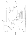
- FIG. 1 shows a brake device 10 with an oil pump 26 and a pressure accumulator 24, via which a control variable in the form of a hydraulic oil pressure can be generated.
- the braking device 10 further comprises operating means 20 with a brake pedal 42 operable by an operator for acting on a brake valve 30 and a wheel brake 12.
- the operating means 20 and the wheel brake 12 are hydraulically connected to each other via a first hydraulic line 32 and a second hydraulic line 46.
- the first hydraulic line 32 forms a branch 34 to a hydraulic oil reservoir 36. Upstream of this branch 34, a first throttle valve 38 and a second throttle valve 40 are arranged parallel to each other. A third throttle valve 58 is disposed downstream of the branch 34 in the conduit to the hydraulic oil reservoir 36. The function of this arrangement will be described below.
- the wheel brake device 12 comprises a first actuator 14 in the form of a first cylinder-piston unit, a second actuator 44 in the form of a second cylinder-piston unit and a friction pair 16, which comprises a friction disc 48 with friction linings, not shown, and a thrust washer 50.
- the friction disc 48 is rotatably arranged about a rotation axis A and the thrust washer 50 and the actuators 14, 44 are arranged rotationally fixed relative to the axis of rotation A.
- the thrust washer 50 is axially movable relative to the axis of rotation A.
- the configuration of the friction pair 16 can also be chosen differently, for example with a brake disc and at least one brake pad.
- return means 18 are provided in the form of a helical compression spring, in principle, other types of springs may be appropriate.
- the return means 18 are based on the one hand in a manner not shown on a housing 66 of the wheel brake 12 from.
- the housing 66 may be a ring housing in a typical embodiment or alternatively be designed as a caliper housing.
- the return means 18 are based on the thrust washer 50.
- the return means 18 are biased between the housing 66 and the thrust washer 50, so that the thrust washer 50 is acted upon in the direction of the friction disc 48 by the bias. As a result, at least one application of the thrust washer 50 is achieved against the friction disc 48.
- a compensating element 22 in the form of a helical tension spring is arranged between the first actuator 14 and the thrust washer 50.
- the first actuator 14 and the thrust washer 50 are mutually movable or zugnachgiebig connected to each other. The function of the thereby possible relative movement between the first actuator 2 and the thrust washer 20 will be described below.
- the function of the braking device 10 according to the invention is in the normal operating mode as follows: By driving the oil pump 26, for example by an internal combustion engine of an agricultural utility vehicle, not shown, a hydraulic pressure in the braking device 10 is generated, which is stored in the pressure accumulator 24. With regard to the normal operating mode, a distinction must be made between a braked state and an unbraked state.
- the brake valve 30 opens by a corresponding amount, so that a certain volume of pressurized hydraulic oil can pass through the second hydraulic line 46 to the second actuator 44.
- the thrust plate 50 is acted upon by the second actuator 44 in the direction of the friction disc 48 and a frictional contact between the friction pair 16 is produced.
- the thrust plate 50 has a clearance against the friction plate 48 before the application, which must be overcome before the thrust washer 50 comes to rest on the friction plate 48.
- the clearance can be between 0.5 mm and 1.5 mm in the unrestrained state of the normal operating mode; preferably it is about 1 mm.
- the clearance arises at the in FIG. 1
- the pressure chamber 52 of the first actuator 14 is supplied with hydraulic pressure, so that the piston 54 and move the coupled thereto drawbar 56 with the coil spring 22 and the thrust washer 50 of the friction disc 48.
- the return means 18 are compressed.
- the spring rates of the return means 18 and the compensating element 22 are coordinated such that the spring rate of the compensating element 22 or the total spring rate of several - not shown - compensation elements is higher than that of the return means 18, so that in the adjusting movement of the air gap, the helical compression spring 18 is compressed without the compensating element 22 being deflected equally.
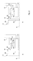
- FIGS. 2a and 2b show alternative embodiments of the first actuator 14.
- a compensation element 64 is arranged in the form of a helical tension spring between the first actuator 14 and the housing 66 of the wheel brake 12.
- the first actuator 14 is movable in a manner not shown parallel to the axis of rotation A in the housing 66.
- a compensation element 68 is arranged in the form of a hydraulic spring accumulator in the hydraulic line 32.
- the spring rates of the balancing members 64 and 68 are designed to be higher than the spring rate of the return means 18.
- the compensation elements 22, 64 and 68 each serve to override an application of the brake by the second actuator 44.
- the function of the compensation elements 22, 64, 68 is crucial for the transition of the unbraked state in the braked state of the normal operating mode.
- the second actuator 44 urges the thrust washer 50 against the friction disk 48 or in the direction of the friction disk 48.
- the respective compensating element 22, 64, 68 permits a relative movement between the thrust washer 50 and the thrust washer 50 first actuator 14, which, as described above, the thrust washer 50 away from the friction disc 48 due to the hydraulic pressure for adjusting the clearance.
- the transition from normal mode to backup mode occurs when there is no or no sufficient hydraulic oil pressure available. This may for example be the case when the promotion has been noticed by the oil pump 26, there is a leakage or a buckling or compression of a hydraulic line. In such a case, the hydraulic pressure in the hydraulic line 32 decreases as the oil flows into the hydraulic oil reservoir 36 via the branch 34 through the throttle valve 24. If the hydraulic pressure in the first actuator 14 falls below a certain level, so that the force of the impact disk 50 falls below the restoring force of the restoring means 18 on the thrust washer 50, the thrust washer 50 is acted upon by the restoring means 18 against the friction disk 48, then that the clearance is at least almost eliminated. It can also be provided that after removal of the clearance already a certain braking effect is achieved.
- the brake device 10 is in the safety mode in which in known and unspecified manner, the operator by means of the brake pedal 42 via the brake valve 30, a hydraulic pressure in the hydraulic line 46 - with reduced volume capacity of the brake valve 30 - can generate to the second actuator 44, the thrust washer 50 to act against the friction disc 48 and to generate a frictional engagement.
- a hydraulic pressure in the hydraulic line 46 - with reduced volume capacity of the brake valve 30 - can generate to the second actuator 44, the thrust washer 50 to act against the friction disc 48 and to generate a frictional engagement.
- the first embodiment shown in FIG. 1 supplies the oil pump 26 via the check valve 28, the pressure accumulator 24 with oil pressure.
- the accumulator 24 is connected via the hydraulic line 60 to the brake valve 30.
- the hydraulic line 32 From the hydraulic line 60 branches off as a control line or pilot line, the hydraulic line 32 for supplying the first actuator 14 in the form of the first cylinder-piston unit.
- the branch of the hydraulic line 32 is structurally integrated by the hydraulic line 60 into a housing of the operating means 20.
- the braking device 10 falls only in the backup mode when the oil pressure in the accumulator 24 by relieving the hydraulic line 32 into the hydraulic oil reservoir 36 or by brake application so far dropped is that the hydraulic pressure in the first actuator 14 falls below a certain level, so that the force of the application to the thrust washer 50, the restoring force of the return means 18 on the thrust washer 50 below, as described above.
- the oil pump 26 also supplies via a check valve 28, the pressure accumulator 24 with oil pressure, although the hydraulic line 32 branches off from a hydraulic line 62 between the oil pump 26 and the check valve 28 as a control line or pilot line.
- the branch of the hydraulic line 32 from the hydraulic line 62 and the check valve 28 is structurally integrated into a housing of the operating means 20.
- the oil supply fails, for example, when the oil pump 26 is no longer driven, the braking device 10 falls into the backup mode, when the oil pressure in the hydraulic line 32 has fallen by discharge into the hydraulic oil reservoir 36 so far that the hydraulic pressure in the first actuator 14 falls below a certain level, so that the force of the application to the thrust washer 50, the restoring force of the return means 18 on the thrust washer 50 falls below, as described above.
- the oil pressure in the pressure accumulator 24 does not have to be used up first.
- the brake device 10 according to the second embodiment thus falls after the elimination of the pressure supply faster in the backup mode as the braking device 10 according to the first embodiment.
- a different pedal feeling compared to an operation of a brake device 10 according to the first embodiment is determined by a larger pedal travel, since the volume of oil required in the brake valve 30 to fill the wheel-side brake piston is limited.
- the pedal feel of the first embodiment is determined by maintaining the normal operation mode up to a pressure drop in the pressure accumulator 24. Until then, the operator learns therefore an unchanged pedal feel and then the pedal feel is determined by the backup mode in which the operator by means of the brake pedal 42 via the brake valve 30 has to apply the hydraulic oil pressure and the oil volume for the second actuator 44.
- the pedal feel of the second embodiment is determined by the fact that due to the failure of the pressure supply, the brake device 10 has fallen into the backup mode, so the first actuator 14 no longer maintains leechth, the second actuator 44, however, for a certain number of braking via an actuation of the brake valve 30th be supplied by the brake pedal 42 with oil pressure from the accumulator 24.
- the second actuator 44 for a certain number of braking via an actuation of the brake valve 30th be supplied by the brake pedal 42 with oil pressure from the accumulator 24.
Landscapes
- Engineering & Computer Science (AREA)
- General Engineering & Computer Science (AREA)
- Mechanical Engineering (AREA)
- Regulating Braking Force (AREA)
- Valves And Accessory Devices For Braking Systems (AREA)
Abstract
Description
- Die Erfindung betrifft eine Bremsvorrichtung für ein Fahrzeug, umfassend eine Radbremseinrichtung mit einem Aktuator, einer Reibpaarung und Rückstellmitteln, ferner Bedienmittel zur Ansteuerung der Radbremseinrichtung, wobei die Bremsvorrichtung mittels einer Steuergröße in einem Normalbetriebsmodus betreibbar ist und bei Unterschreiten eines Schwellenwertes der Steuergröße in einem Sicherungsmodus betreibbar ist, wobei im Normalbetriebsmodus die Steuergröße den Aktuator derart beaufschlagt, dass der Aktuator zwischen der Reibpaarung ein erstes Lüftspiel einstellt und wobei im Sicherungsmodus die Rückstellmittel zwischen der Reibpaarung ein gegenüber dem ersten Lüftspiel verringertes zweites Lüftspiel einstellen.
- Die Einstellung eines Sicherungsmodus mit einem verringerten Lüftspiel wird bei der Auslegung derartiger Bremsvorrichtungen angestrebt, da die Bedienmittel zur Ansteuerung der Radbremseinrichtung, die beispielsweise als Bremsventil ausgestaltet sein können, im Sicherungsmodus eine verringerte Volumenkapazität bereitstellen. Somit kann ein besseres Ansprechverhalten der Bremse im Sicherungsmodus erreicht werden.
- Die
EP 2 146 109 A1 zeigt eine Scheibenbremsvorrichtung mit einem Bremsventil und einem hydraulischen Retraktorsystem, um in einem Normalbetriebsmodus das Lüftspiel zu maximieren und in einem Sicherungsmodus ein manuelles Abbremsen wirksam zu ermöglichen. Das Retraktorsystem umfasst einen Bremskolben, eine Bremsfeder und einen Retraktorstößel. Der Retraktorstößel ist starr mit dem Bremskolben verbunden. - Ausgehend hiervon besteht die Aufgabe der Erfindung darin, eine Bremsvorrichtung mit einer verbesserten Ansteuerung der Radbremseinrichtung in den Betriebsmodi bereitzustellen.
- Die Aufgabe wird gelöst durch eine Bremsvorrichtung für ein Fahrzeug, umfassend eine Radbremseinrichtung mit einem Aktuator, einer Reibpaarung und Rückstellmitteln, ferner Bedienmittel zur Ansteuerung der Radbremseinrichtung, wobei die Bremsvorrichtung mittels einer Steuergröße in einem Normalbetriebsmodus betreibbar ist und bei Unterschreiten eines Schwellenwertes der Steuergröße in einem Sicherungsmodus betreibbar ist, wobei im Normalbetriebsmodus die Steuergröße den Aktuator derart beaufschlagt, dass der Aktuator zwischen der Reibpaarung ein erstes Lüftspiel einstellt und wobei im Sicherungsmodus die Rückstellmittel zwischen der Reibpaarung ein gegenüber dem ersten Lüftspiel verringertes zweites Lüftspiel einstellen, wobei bei einer Ansteuerung der Radbremseinrichtung die Steuergröße mittels eines Ausgleichselements übersteuerbar ist.
- Hierbei bedeutet Reibpaarung beispielsweise eine Anordnung aus einer radwellendrehenden Bremsscheibe und zumindest einem gehäusefesten Bremsbelag, der gegen die Bremsscheibe zur Erzeugung eines Reibkontaktes beaufschlagt wird. Alternativ kann eine Reibpaarung auch aus einer radwellendrehenden Reibscheibe mit Reibbelägen und zumindest einem gegen die Reibscheibe beaufschlagbaren gehäusefesten Anlaufelement bestehen. Das Anlaufelement kann als runde, zu der Radwelle konzentrisch angeordnete Anlaufscheibe gestaltet sein. Bevorzugt sind mehrere Rückstellmittel über den Umfang angeordnet, beispielsweise drei oder vier. Die Rückstellmittel können als Schraubendruckfeder ausgeführt sein. Die Bremsvorrichtung kann auch als Trommelbremse, Backenbremse oder Kegelbremse ausgeführt sein.
- Bei einem Lüftspiel handelt es sich um einen zumindest minimalen axialen oder radialen Spalt, d.h. axial bzw. radial bezogen auf die Drehachse der Bremsvorrichtung, zwischen den Elementen, die die Reibpaarung bilden, d.h. zwischen der Bremsscheibe und dem zumindest einen Bremsbelag oder der Reibscheibe und dem zumindest einen Anlaufelement. Der Aktuator übt eine Stellwirkung auf die Reibpaarung zur Erzeugung eines Lüftspiels aus. Eine gegenläufige Wirkung, d.h. eine Rückstellwirkung, üben die Rückstellmittel auf die Reibpaarung auf.
- Bei der erfindungsgemäßen Bremsvorrichtung ist von Vorteil, dass im Normalbetriebsmodus eine Ansteuerung der Radbremseinrichtung beziehungsweise eine Beaufschlagung der Reibpaarung in Richtung eines Reibkontaktes erfolgen kann, ohne dass hierbei die Stellwirkung beziehungsweise die Stellkraft des Aktuators überwunden werden muss, dass heißt ohne dass diese Stellkraft zusätzlich aufgebracht werden muss. Vielmehr wird erfindungsgemäß sichergestellt, dass die die Stellkraft auslösende Steuergröße übersteuert wird. Diese Stellkraft ist bei einem hydraulischen Aktuator das Produkt aus Druck und Kolbenflächen, wenn der Aktuator als Zylinder-Kolben-Einheit gestaltet ist, und kann bei Drücken von bis über 200 bar bei einem landwirtschaftlichen Nutzfahrzeug signifikant sein. Weiterhin besteht der Vorteil bei der erfindungsgemäßen Bremsvorrichtung darin, dass bei einer verringerten Volumenkapazität der Bedienmittel im Sicherungsmodus infolge des verringerten Lüftspiel dennoch eine sichere Bremsung bei einem schnellen Ansprechen erfolgen kann.
- Bevorzugt umfasst das Ausgleichselement zur Übersteuerung der Steuergröße Federmittel. Von Vorteil ist hierbei, dass diese Ausgestaltung einfach aufgebaut ist und Normteile Verwendung finden können.
- In einer ersten konkreten Ausgestaltung kann der Aktuator über die Federmittel mit der Reibpaarung zugnachgiebig und/oder drucknachgiebig verbunden sein. In einer zweiten konkreten Ausgestaltung kann der Aktuator über die Federmittel mit einem Gehäuse der Radbremseinrichtung zugnachgiebig und/oder drucknachgiebig verbunden sein. Bei dem Gehäuse kann es sich beispielsweise um ein Bremssattelgehäuse handeln. Von Vorteil ist bei beiden Ausgestaltungen der einfache Aufbau mittels Federn als Normteile.
- In einer weiteren konkreten Ausgestaltung können die Federmittel einen hydraulischen Speicher umfassen. Von Vorteil ist bei dieser Ausgestaltung, dass sie geringe Anforderungen an den Platzbedarf im Bereich der Bremse stellt, da der Speicher außerhalb des Gehäuses der Radbremseinrichtung angeordnet werden kann.
- Bevorzugt ist die Steuergröße ein von einer Ölpumpe erzeugter hydraulischer Öldruck. In vorteilhafterweise wird hierdurch unabhängig von einer Bedienung der Bremsvorrichtung ein Öldruck für den Normalbetriebsmodus bereitgestellt.
- In weiterhin bevorzugter Ausgestaltung ist ein Druckspeicher vorgesehen, in dem der hydraulische Öldruck speicherbar ist. Hierdurch wird in vorteilhafterweise über einen gewissen Zeitraum eine von einer Öldruckquelle unabhängige Druckversorgung gewährleistet. Alternativ kann anstelle der Hydraulik auch eine Pneumatik vorgesehen sein.
- In weiterhin bevorzugter Ausgestaltung umfassen die Bedienmittel ein hydraulisches Bremsventil. Insbesondere ist bevorzugt, dass zwischen der Ölpumpe und den Bedienmitteln ein Rückschlagventil angeordnet ist. Hierdurch ergibt sich als mögliche Anordnung, dass das Rückschlagventil zwischen der Ölpumpe und dem hydraulischen Bremsventil in einer Zuleitung angeordnet ist.
- Bei einer ersten Ausführungsform der erfindungsgemäßen Bremsvorrichtung ist der Druckspeicher zwischen dem Rückschlagventil und dem Bremsventil angeordnet. Dies kann bedeuten, dass der Druckspeicher in einer hydraulischen Verbindungsleitung zwischen dem Rückschlagventil und dem Bremsventil in Reihe angeordnet ist.
- Bevorzugt wird bei der ersten Ausführungsform die Steuergröße für den Aktuator zwischen dem Druckspeicher und dem hydraulischen Bremsventil abgegriffen. Bei der ersten Ausführungsform ist von Vorteil, dass nach einem Ausfall der Ölpumpe weiterhin hydraulischer Druck in der Hydraulikleitung zu dem Aktuator vorhanden ist.
- Bei einer zweiten Ausführungsform der erfindungsgemäßen Bremsvorrichtung zweigt der Druckspeicher zwischen dem Rückschlagventil und dem hydraulischen Bremsventil ab. Weiterhin bevorzugt wird die Steuergröße für den Aktuator zwischen dem Rückschlagventil und der Ölpumpe abgegriffen. Bei der zweiten Ausführungsform ist von Vorteil, dass nach einem Ausfall der Ölpumpe der Aktuator über die Hydraulikleitung nicht mehr mit hydraulischen Druck versorgt wird, so dass nach Unterschreiten des Schwellenwerten der Steuergröße die erfindungsgemäße Bremsvorrichtung in den Sicherungsmodus fällt, während der Druckspeicher das Bremsventil wie im Normalbetriebsmodus noch für eine gewisse Anzahl von Bremsungen mit Öldruck versorgt, was als Überlagerung bezeichnet werden kann.
- Bevorzugt handelt es sich bei dem Aktuator um eine hydraulische Zylinder-Kolben-Anordnung. Hierbei kann insbesondere vorgesehen sein, dass die Ansteuerung des Aktuators ausgehend von den Bedienmitteln mittels einer Hydraulikleitung erfolgt.
- Bevorzugt ist für alle Ausführungsformen, dass die Hydraulikleitung einen Abzweig zu einem Hydraulikreservoir aufweist zur Entlastung des hydraulischen Drucks beim Wechsel vom Normalbetriebsmodus in den Sicherungsmodus. Hierdurch wird gewährleistet, dass bei einem Wegfall der Druckversorgung, beispielsweise durch die Ölpumpe, sich der hydraulische Druck in der Hydraulikleitung abbaut, so dass die Bremsvorrichtung in den Sicherungsmodus fällt. Weiterhin ist bevorzugt, dass in der Hydraulikleitung zumindest ein Drosselventil angeordnet ist, wobei insbesondere bevorzugt ist, dass zumindest ein Drosselventil vor dem Abzweig zu dem Hydraulikreservoir und eine Drosselventil nach dem Abzweig zu dem Hydraulikreservoir angeordnet ist. Hierdurch wird in vorteilhafterweise gewährleistet, dass ein Öldurchfluss in das Hydraulikreservoir auf einen definierten Wert begrenzt wird. Weiterhin kann man über die Abstimmung des Drosselventils den Druckabfall über der Zeit bei fehlender bzw. ausgefallener Druckversorgung einstellen. In weiterhin bevorzugter Ausgestaltung können zwei in Reihe geschaltete widerstandsäquivalente Drosselventile oder Blenden vorgesehen sein. Hierdurch kann ein Zusetzen des Drosselventils nach dem Abzweig vermieden werden.
- Bevorzugt weist die Radbremseinheit einen zweiten Aktuator auf, insbesondere in Form einer Zylinder-Kolben-Einheit, mittels dem im Normalbetriebsmodus und im Sicherungsmodus nach Ansteuerung durch die Bedienmittel die Beaufschlagung der Reibpaarung in Richtung eines Reibkontaktes beziehungsweise Reibschlusses erfolgt. Bevorzugt wird der zweite Aktuator mittels der Steuergröße angesteuert.
- Für alle Ausführungsformen ist weiterhin bevorzugt, dass das Bremsventil, das Rückschlagventil und der Abgriff der Steuergröße für den Aktuator baulich integriert gestaltet sind, vorzugsweise innerhalb eines Gehäuses. Bevorzugt ist auch der Abgriff zu dem Druckspeicher integriert. Hierdurch ist gewährleistet, dass das Risiko eine Leitungsknickung reduziert wird und es wird erreicht, dass für das Bremsventil und den ersten Aktuator und den zweiten Aktuator unterschiedliche Versorgungs- oder Signalzustände vorliegen können.
- Bevorzugte Ausführungsbeispiele der erfindungsgemäßen Bremsvorrichtung werden anhand der Figuren beschrieben. Hierin zeigen
- Figur 1
- eine erfindungsgemäße Bremsvorrichtung in einer ersten Ausführungsform mit einer ersten Variante eines ersten Aktuators,
- Figur 2a
- eine Einzelheit der Radbremseinrichtung mit einer zweiten Variante eines ersten Aktuators,
- Figur 2b
- eine Einzelheit der Radbremseinrichtung mit einer dritten Variante eines ersten Aktuators und
- Figur 3
- eine erfindungsgemäße Bremsvorrichtung in einer zweiten Ausführungsform.
-
Figur 1 zeigt eine Bremsvorrichtung 10 mit einer Ölpumpe 26 und einem Druckspeicher 24, über die eine Steuergröße in Form eines hydraulischen Öldrucks erzeugt werden kann. Die Bremsvorrichtung 10 umfasst ferner Bedienmittel 20 mit einem durch eine Bedienperson bedienbaren Bremspedal 42 zum Einwirken auf ein Bremsventil 30 und eine Radbremseinrichtung 12. Die Bedienmittel 20 und die Radbremseinrichtung 12 sind über eine erste Hydraulikleitung 32 und eine zweite Hydraulikleitung 46 hydraulisch miteinander verbunden. - Die erste Hydraulikleitung 32 bildet einen Abzweig 34 zu einem Hydraulikölreservoir 36 aus. Stromaufwärts dieses Abzweigs 34 sind ein erstes Drosselventil 38 und ein zweites Drosselventil 40 parallel zueinander angeordnet. Ein drittes Drosselventil 58 ist stromabwärts des Abzweigs 34 in der Leitung zu dem Hydraulikölreservoir 36 angeordnet. Die Funktion dieser Anordnung wird weiter unten beschrieben.
- Die Radbremseinrichtung 12 umfasst einen ersten Aktuator 14 in Form einer ersten Zylinder-Kolben-Einheit, einen zweiten Aktuator 44 in Form einer zweiten Zylinder-Kolben-Einheit und eine Reibpaarung 16, die eine Reibscheibe 48 mit nicht dargestellten Reibbelägen und eine Anlaufscheibe 50 umfasst. Die Reibscheibe 48 ist drehbar um eine Drehachse A angeordnet und die Anlaufscheibe 50 und die Aktuatoren 14, 44 sind gegenüber der Drehachse A drehfest angeordnet. Die Anlaufscheibe 50 ist bezogen auf die Drehachse A axial beweglich. Die Konfiguration der Reibpaarung 16 kann auch anders gewählt werden, beispielsweise mit einer Bremsscheibe und zumindest einem Bremsbelag.
- Ferner sind Rückstellmittel 18 in Form einer Schraubendruckfeder vorgesehen, wobei prinzipiell auch andere Federtypen zweckmäßig sein können. Die Rückstellmittel 18 stützen sich zur einen Seite in nicht näher dargestellter Weise an einem Gehäuse 66 der Radbremseinrichtung 12 ab. Das Gehäuse 66 kann in typischer Ausgestaltung ein Ringgehäuse sein oder alternativ als Bremssattelgehäuse ausgeführt sein. Zur anderen Seite stützen sich die Rückstellmittel 18 an der Anlaufscheibe 50 ab. Die Rückstellmittel 18 sind zwischen dem Gehäuse 66 und der Anlaufscheibe 50 vorgespannt, so dass durch die Vorspannung die Anlaufscheibe 50 in Richtung der Reibscheibe 48 beaufschlagt. Hierdurch wird zumindest ein Anlegen der Anlaufscheibe 50 gegen die Reibscheibe 48 erreicht.
- Weiterhin ist zwischen dem ersten Aktuator 14 und der Anlaufscheibe 50 ein Ausgleichselement 22 in Form einer Schraubenzugfeder angeordnet. Hierdurch sind der erste Aktuator 14 und die Anlaufscheibe 50 gegeneinander bewegbar beziehungsweise zugnachgiebig miteinander verbunden. Die Funktion der hierdurch möglichen Relativbewegung zwischen dem ersten Aktuator 2 und der Anlaufscheibe 20 wird weiter unten beschrieben.
- Die Funktion der erfindungsgemäßen Bremsvorrichtung 10 ist im Normalbetriebsmodus folgendermaßen: Durch den Antrieb der Ölpumpe 26, beispielsweise durch eine nicht dargestellte Verbrennungskraftmaschine eines landwirtschaftlichen Nutzfahrzeugs, wird ein hydraulischer Druck in der Bremsvorrichtung 10 erzeugt, der in dem Druckspeicher 24 gespeichert wird. Bezüglich des Normalbetriebsmodus muss zwischen einem gebremsten Zustand und einem ungebremsten Zustand unterschieden werden.
- Bei einer Betätigung der Bedienmittel 20 über das Bremspedal 42 durch eine Bedienperson wird der gebremste Zustand des Normalbetriebsmodus eingeleitet. Durch die Betätigung des Bremspedals 42 öffnet sich das Bremsventil 30 um einen entsprechenden Betrag, so dass ein bestimmtes Volumen des unter Druck stehenden Hydrauliköls durch die zweite Hydraulikleitung 46 zu dem zweiten Aktuator 44 gelangen kann. Hierrüber wird im Normalbetriebsmodus durch den zweiten Aktuator 44 die Anlaufplatte 50 in Richtung der Reibscheibe 48 beaufschlagt und ein Reibkontakt zwischen der Reibpaarung 16 hergestellt. Die Anlaufplatte 50 hat vor der Beaufschlagung ein Lüftspiel gegenüber der Reibplatte 48, welches überwunden werden muss, bevor die Anlaufscheibe 50 an der Reibplatte 48 zur Anlage kommt. Das Lüftspiel kann im ungebremsten Zustand des Normalbetriebsmodus zwischen 0,5 mm und 1,5 mm betragen; vorzugsweise beträgt es etwa 1 mm.
- Das Lüftspiel stellt sich bei der in
Figur 1 gezeigten ersten Ausführung des ersten Aktuators 14 folgendermaßen ein: Über die Hydraulikleitung 32 wird die Druckkammer 52 des ersten Aktuators 14 mit hydraulischem Druck versorgt, so dass sich der Kolben 54 und die an diesen gekoppelte Zugstange 56 mit der Schraubenzugfeder 22 und die Anlaufscheibe 50 von der Reibscheibe 48 wegbewegen. Durch diese Bewegung werden die Rückstellmittel 18 komprimiert. Hierbei sind die Federraten der Rückstellmittel 18 und des Ausgleichselements 22 derart aufeinander abgestimmt, dass die Federrate des Ausgleichselements 22 oder die Gesamtfederrate mehrerer - nicht dargestellter - Ausgleichselemente höher ist als die des Rückstellmittels 18, so dass bei der Einstellbewegung des Lüftspiels die Schraubendruckfeder 18 komprimiert wird, ohne dass das Ausgleichselement 22 gleichermaßen ausgelenkt wird. - Die
Figuren 2a und 2b zeigen alternative Ausführungen des ersten Aktuators 14. Bei der Alternative derFigur 2a ist ein Ausgleichselement 64 in Form einer Schraubenzugfeder zwischen dem ersten Aktuator 14 und dem Gehäuse 66 der Radbremseinheit 12 angeordnet. Der erste Aktuator 14 ist in nicht näher dargestellter Weise parallel zu der Drehachse A in dem Gehäuse 66 bewegbar. Bei der alternativen Ausführung derFigur 2b ist ein Ausgleichselement 68 in Form eines hydraulischen Federspeichers in der Hydraulikleitung 32 angeordnet. Auch bei diesen alternativen Ausführungen sind die Federraten der Ausgleichselemente 64 bzw. 68 so ausgelegt, dass sie höher sind als die Federrate der Rückstellmittel 18. - Bei den drei beschriebenen Ausführungen des ersten Aktuators dienen die Ausgleichselemente 22, 64 und 68 jeweils zur Übersteuerung einer Beaufschlagung der Bremse durch den zweiten Aktuator 44. Die Funktion der Ausgleichselemente 22, 64, 68 ist entscheidend für den Übergang des ungebremsten Zustandes in den gebremsten Zustand des Normalbetriebsmodus. Wie oben beschrieben, beaufschlagt der zweite Aktuator 44 bei Betätigung des Bremspedals 42 und anliegendem hydraulischen Öldruck die Anlaufscheibe 50 gegen die Reibscheibe 48 beziehungsweise in Richtung der Reibscheibe 48. Das jeweilige Ausgleichselement 22, 64, 68 ermöglicht hierbei eine Relativbewegung zwischen der Anlaufscheibe 50 und dem ersten Aktuator 14, der, wie oben beschrieben, aufgrund des hydraulischen Druck zur Einstellung des Lüftspiels die Anlaufscheibe 50 von der Reibscheibe 48 wegbeaufschlagt. Im gebremsten Zustand des Normalbetriebsmodus überwinden somit der zweite Aktuator 44 und die parallel wirkende Federkraft der Rückstellmittel 18 die Federkraft des jeweiligen Ausgleichselements 22, 64, 68, so dass dieses ausgelenkt wird und der erste Aktuator 14 in sich keine beziehungsweise annähernd keine Bewegung erfährt. Da in diesem Zustand die Steuergröße weiterhin den ersten Aktuator 14 beaufschlagt, wird die Steuergröße durch das jeweilige Ausgleichselement 22, 64, 68 übersteuert.
- Der Übergang vom Normalbetriebsmodus in den Sicherungsmodus erfolgt, wenn kein oder kein ausreichender hydraulischer Öldruck mehr zur Verfügung steht. Dies kann beispielsweise der Fall sein, wenn die Förderung durch die Ölpumpe 26 aufgefallen ist, eine Leckage oder eine Knickung oder Stauchung einer Hydraulikleitung vorliegt. In einem solchen Fall baut sich der hydraulische Druck in der Hydraulikleitung 32 in dem Maße ab, in dem über den Abzweig 34 durch das Drosselventil 24 Öl in das Hydraulikölreservoir 36 fließt. Unterschreitet nun der hydraulische Druck in dem ersten Aktuator 14 eine bestimmtes Maß, so dass die Kraft der Beaufschlagung auf die Anlaufscheibe 50 die Rückstellkraft der Rückstellmittel 18 auf die Anlaufscheibe 50 unterschreitet, wird die Anlaufscheibe 50 durch die Rückstellmittel 18 gegen die Reibscheibe 48 beaufschlagt, so dass das Lüftspiel zumindest nahezu beseitigt ist. Es kann auch vorgesehen sein, dass nach Beseitigung des Lüftspiels bereits eine gewisse Bremswirkung erzielt wird. In diesem Zustand befindet sich die Bremsvorrichtung 10 im Sicherungsmodus, in dem in bekannter und nicht näher erläuterter Weise die Bedienperson mittels des Bremspedals 42 über das Bremsventil 30 einen hydraulischen Druck in der Hydraulikleitung 46 - bei verringerter Volumenkapazität des Bremsventils 30 - erzeugen kann, um über den zweiten Aktuator 44 die Anlaufscheibe 50 gegen die Reibscheibe 48 zu beaufschlagen und einen Reibschluss zu erzeugen. Somit muss bei Bedienung der Bremsvorrichtung 10 im Sicherungsmodus kein oder zumindest nur ein minimales Lüftspiel überwunden werden, bevor ein Reibschluss zwischen der Reibpaarung 16 bestehend aus Anlaufscheibe 50 und Reibscheibe 48 aufgebaut wird.
- Der Unterschied zwischen dem Ausführungsbeispiel der
Figur 1 und dem derFigur 3 der erfindungsgemäßen Bremsvorrichtung 10 wird nachfolgend beschrieben, wobei lediglich aus Gründen einer vereinfachten Darstellung bei beiden Ausführungsbeispielen die erste Variante des ersten Aktuators 14 mit dem Ausgleichselement 22 gezeigt ist. Bei beiden Ausführungsbeispielen der Bremsvorrichtung 10 kann eine der drei alternativen Ausführungen des ersten Aktuators 14 Verwendung finden. - Bei dem ersten Ausführungsbeispiel, gezeigt in
Figur 1 , versorgt die Ölpumpe 26 über das Rückschlagventil 28 den Druckspeicher 24 mit Öldruck. Der Druckspeicher 24 ist über die Hydraulikleitung 60 mit dem Bremsventil 30 verbunden. Von der Hydraulikleitung 60 zweigt als Steuerleitung bzw. Pilotleitung die Hydraulikleitung 32 zur Versorgung des ersten Aktuators 14 in Form der ersten Zylinder-Kolben-Einheit ab. Vorzugsweise ist der Abzweig der Hydraulikleitung 32 von der Hydraulikleitung 60 baulich in ein Gehäuse der Bedienmittel 20 integriert. Fällt bei diesem ersten Ausführungsbeispiel die Ölversorgung aus, beispielsweise wenn die Ölpumpe 26 nicht mehr angetrieben wird, fällt die Bremsvorrichtung 10 erst in den Sicherungsmodus, wenn der Öldruck in dem Druckspeicher 24 durch Entlastung der Hydraulikleitung 32 in das Hydraulikölreservoir 36 oder durch Bremsbetätigung so weit abgefallen ist, dass der hydraulische Druck in dem ersten Aktuator 14 ein bestimmtes Maß unterschreitet, so dass die Kraft der Beaufschlagung auf die Anlaufscheibe 50 die Rückstellkraft der Rückstellmittel 18 auf die Anlaufscheibe 50 unterschreitet, wie oben beschrieben. - Bei dem zweiten Ausführungsbeispiel, gezeigt in
Figur 3 , versorgt die Ölpumpe 26 ebenfalls über ein Rückschlagventil 28 den Druckspeicher 24 mit Öldruck, wobei allerdings von einer Hydraulikleitung 62 zwischen der Ölpumpe 26 und dem Rückschlagventil 28 die Hydraulikleitung 32 als Steuerleitung bzw. Pilotleitung abzweigt. Vorzugsweise ist hier der Abzweig der Hydraulikleitung 32 von der Hydraulikleitung 62 und das Rückschlagventil 28 baulich in ein Gehäuse der Bedienmittel 20 integriert. Fällt bei diesem zweiten Ausführungsbeispiel die Ölversorgung aus, beispielsweise wenn die Ölpumpe 26 nicht mehr angetrieben wird, fällt die Bremsvorrichtung 10 in den Sicherungsmodus, wenn der Öldruck in der Hydraulikleitung 32 durch Entlastung in das Hydraulikölreservoir 36 so weit abgefallen ist, dass der hydraulische Druck in dem ersten Aktuator 14 eine bestimmtes Maß unterschreitet, so dass die Kraft der Beaufschlagung auf die Anlaufscheibe 50 die Rückstellkraft der Rückstellmittel 18 auf die Anlaufscheibe 50 unterschreitet, wie oben beschrieben. Bei dem zweiten Ausführungsbeispiel muss somit nicht zuerst der Öldruck in dem Druckspeicher 24 aufgebraucht sein. Die Bremsvorrichtung 10 gemäß dem zweiten Ausführungsbeispiel fällt somit nach Wegfall der Druckversorgung schneller in den Sicherungsmodus als die Bremsvorrichtung 10 gemäß dem ersten Ausführungsbeispiel. - Nach einem Wechsel der Bremsvorrichtung 10 in den Sicherungsmodus ergibt sich für die Bedienperson, die eine Bremsvorrichtung 10 gemäß dem zweiten Ausführungsbeispiel bedient, ein anderes Pedalgefühl verglichen mit einer Bedienung einer Bremsvorrichtung 10 gemäß dem ersten Ausführungsbeispiel. Im Wesentlichen wird das andere Pedalgefühl durch einen größeren Pedalweg bestimmt, da das für das Füllen des radseitigen Bremskolbens erforderliche Ölvolumen in dem Bremsventil 30 begrenzt ist. Das Pedalgefühl des ersten Ausführungsbeispiels wird dadurch bestimmt, dass der Normalbetriebsmodus bis zu einem Druckabfall im Druckspeicher 24 aufrechterhalten wird. Bis dahin erfährt die Bedienperson demnach ein unverändertes Pedalgefühl und danach ist das Pedalgefühl durch den Sicherungsmodus bestimmt, in dem die Bedienperson mittels des Bremspedals 42 über das Bremsventils 30 den hydraulischen Öldruck und das Ölvolumen für den zweiten Aktuator 44 aufbringen muss.
- Das Pedalgefühl des zweiten Ausführungsbeispiels wird dadurch bestimmt, dass infolge des Ausfalls der Druckversorgung die Bremsvorrichtung 10 in den Sicherungsmodus gefallen ist, also der erste Aktuator 14 kein Lüftspiel aufrechthält, der zweite Aktuator 44 allerdings für eine gewisse Anzahl von Bremsungen über eine Betätigung des Bremsventils 30 mittels des Bremspedals 42 mit Öldruck aus dem Druckspeicher 24 versorgt werden. Somit muss bei einer normalen Bremsung mittels des noch bestehenden Öldrucks aus dem Druckspeicher 24 nicht erst ein Lüftspiel überwunden werden, bevor die Reibpaarung 16 in Reibschluss gebracht wird.
-
- 10
- Bremsvorrichtung
- 12
- Radbremseinrichtung
- 14
- Aktuator
- 16
- Reibpaarung
- 18
- Rückstellmittel
- 20
- Bedienmittel
- 22
- Ausgleichselement
- 24
- Druckspeicher
- 26
- Ölpumpe
- 28
- Rückschlagventil
- 30
- Bremsventil
- 32
- Hydraulikleitung
- 34
- Abzweig
- 36
- Hydraulikölreservoir
- 38
- Drosselventil
- 40
- Drosselventil
- 42
- Bremspedal
- 44
- Aktuator
- 46
- Hydraulikleitung
- 48
- Reibscheibe
- 50
- Anlaufscheibe
- 52
- Druckkammer
- 54
- Kolben
- 56
- Zugstange
- 58
- Drosselventil
- 60
- Hydraulikleitung
- 62
- Hydraulikleitung
- 64
- Federmittel
- 66
- Gehäuse
- 68
- Federspeicher
- A
- Drehachse
Claims (15)
- Bremsvorrichtung (10) für ein Fahrzeug, umfassend
eine Radbremseinrichtung (12) mit einem Aktuator (14), einer Reibpaarung (16) und Rückstellmitteln (18), Bedienmittel (10) zur Ansteuerung der Radbremseinrichtung (12), wobei die Bremsvorrichtung (10) mittels einer Steuergröße in einem Normalbetriebsmodus betreibbar ist und bei Unterschreiten eines Schwellenwertes der Steuergröße in einem Sicherungsmodus betreibbar ist, wobei im Normalbetriebsmodus die Steuergröße den Aktuator (14) derart beaufschlagt, dass der Aktuator (14) zwischen der Reibpaarung (16) ein erstes Lüftspiel einstellt und wobei im Sicherungsmodus die Rückstellmittel (18) zwischen der Reibpaarung (16) ein gegenüber dem ersten Lüftspiel verringertes zweites Lüftspiel einstellen, dadurch gekennzeichnet, dass bei einer Ansteuerung der Radbremseinrichtung (12) die Steuergröße mittels eines Ausgleichselements (22, 64, 68) übersteuerbar ist. - Bremsvorrichtung (10) nach Anspruch 1, dadurch gekennzeichnet, dass das Ausgleichselement zur Übersteuerung der Steuergröße Federmittel (22, 64, 68) umfasst.
- Bremsvorrichtung (10) nach Anspruch 2, dadurch gekennzeichnet, dass der Aktuator (14) über die Federmittel (22) mit der Reibpaarung (16) zugnachgiebig und/oder drucknachgiebig verbunden ist.
- Bremsvorrichtung (10) nach Anspruch 2, dadurch gekennzeichnet,dass der Aktuator (14) über die Federmittel (64) mit einem Gehäuse (66) der Radbremseinrichtung (12) zugnachgiebig und/oder drucknachgiebig verbunden ist.
- Bremsvorrichtung (10) nach Anspruch 2, dadurch gekennzeichnet, dass die Federmittel einen hydraulischen Speicher (68) umfassen.
- Bremsvorrichtung (10) nach einem der Ansprüche 1 bis 5, dadurch gekennzeichnet, dass die Steuergröße ein von einer Ölpumpe (26) erzeugter hydraulischer Öldruck ist und dieser in einem Druckspeicher (24) speicherbar ist.
- Bremsvorrichtung (10) nach einem der Ansprüche 1 bis 6, dadurch gekennzeichnet, dass die Bedienmittel (20) ein hydraulisches Bremsventil (30) umfassen.
- Bremsvorrichtung (10) nach Anspruch 6 oder 7, dadurch gekennzeichnet, dass zwischen der Ölpumpe (26) und den Bedienmitteln (20) ein Rückschlagventil (28) angeordnet ist.
- Bremsvorrichtung (10) nach Anspruch 8, dadurch gekennzeichnet, dass der Druckspeicher (24) zwischen dem Rückschlagventil (28) und dem Bremsventil (30) angeordnet ist.
- Bremsvorrichtung (10) nach Anspruch 9, dadurch gekennzeichnet, dass die Steuergröße für den Aktuator (14) zwischen dem Druckspeicher (24) und dem hydraulischen Bremsventil (30) abgegriffen wird.
- Bremsvorrichtung (10) nach Anspruch 9, dadurch gekennzeichnet, dass die Steuergröße für den Aktuator (14) zwischen dem Rückschlagventil (28) und der Ölpumpe (26) abgegriffen wird.
- Bremsvorrichtung (10) nach einem der Ansprüche 1 bis 11,
dadurch gekennzeichnet, dass es sich bei dem Aktuator (14) um eine hydraulische Zylinder-Kolben-Anordnung handelt und dessen Ansteuerung ausgehend von den Bedienmitteln (20) mittels einer Hydraulikleitung (32) erfolgt. - Bremsvorrichtung (10) nach Anspruch 12, dadurch gekennzeichnet, dass die Hydraulikleitung (32) einen Abzweig (34) zu einem Hydraulikölreservoir (36) aufweist zur Entlastung des hydraulischen Drucks beim Wechsel vom Normalbetriebsmodus in den Sicherungsmodus.
- Bremsvorrichtung (10) nach Anspruch 12 oder 13, dadurch gekennzeichnet, dass in der Hydraulikleitung (32) zumindest ein Drosselventil (38) angeordnet ist.
- Bremsvorrichtung (10) nach einem der Ansprüche 12 bis 14, dadurch gekennzeichnet, dass in der Hydraulikleitung (32) zumindest ein Blende angeordnet ist.
Applications Claiming Priority (1)
| Application Number | Priority Date | Filing Date | Title |
|---|---|---|---|
| DE102011082094A DE102011082094A1 (de) | 2011-09-02 | 2011-09-02 | Bremsvorrichtung |
Publications (2)
| Publication Number | Publication Date |
|---|---|
| EP2565487A1 true EP2565487A1 (de) | 2013-03-06 |
| EP2565487B1 EP2565487B1 (de) | 2020-07-15 |
Family
ID=46690432
Family Applications (1)
| Application Number | Title | Priority Date | Filing Date |
|---|---|---|---|
| EP12181223.4A Active EP2565487B1 (de) | 2011-09-02 | 2012-08-21 | Bremsvorrichtung |
Country Status (2)
| Country | Link |
|---|---|
| EP (1) | EP2565487B1 (de) |
| DE (1) | DE102011082094A1 (de) |
Citations (5)
| Publication number | Priority date | Publication date | Assignee | Title |
|---|---|---|---|---|
| US3589478A (en) * | 1969-08-27 | 1971-06-29 | Goodrich Co B F | Brake retractor mechanism |
| US3643763A (en) * | 1970-09-16 | 1972-02-22 | Gen Motors Corp | Combination hydraulically and mechanically actuable disc brake with hydraulic wear adjustment |
| GB2140086A (en) * | 1983-04-25 | 1984-11-21 | Harnischfeger Corp | Fail-safe hydraulic brake |
| US6286635B1 (en) * | 1999-06-01 | 2001-09-11 | Ford Global Technologies, Inc. | Vehicle braking system with actively controlled caliper retractor |
| EP2146109A1 (de) | 2008-07-15 | 2010-01-20 | Deere & Company | Hydraulikscheiben-Bremseneinzugssystem |
-
2011
- 2011-09-02 DE DE102011082094A patent/DE102011082094A1/de not_active Withdrawn
-
2012
- 2012-08-21 EP EP12181223.4A patent/EP2565487B1/de active Active
Patent Citations (5)
| Publication number | Priority date | Publication date | Assignee | Title |
|---|---|---|---|---|
| US3589478A (en) * | 1969-08-27 | 1971-06-29 | Goodrich Co B F | Brake retractor mechanism |
| US3643763A (en) * | 1970-09-16 | 1972-02-22 | Gen Motors Corp | Combination hydraulically and mechanically actuable disc brake with hydraulic wear adjustment |
| GB2140086A (en) * | 1983-04-25 | 1984-11-21 | Harnischfeger Corp | Fail-safe hydraulic brake |
| US6286635B1 (en) * | 1999-06-01 | 2001-09-11 | Ford Global Technologies, Inc. | Vehicle braking system with actively controlled caliper retractor |
| EP2146109A1 (de) | 2008-07-15 | 2010-01-20 | Deere & Company | Hydraulikscheiben-Bremseneinzugssystem |
Also Published As
| Publication number | Publication date |
|---|---|
| EP2565487B1 (de) | 2020-07-15 |
| DE102011082094A1 (de) | 2013-03-07 |
Similar Documents
| Publication | Publication Date | Title |
|---|---|---|
| WO2008128835A1 (de) | Bremsanlage für kraftfahrzeuge | |
| EP2635470A1 (de) | Bremskraftverstärker und verfahren zum betrieb eines bremskraftverstärkers | |
| WO2012059259A1 (de) | Bremskraftverstärker und verfahren zum betrieb eines bremskraftverstärkers | |
| DE3133995C2 (de) | Druckregelventil für eine hydraulische Zweikreisbremsanlage | |
| DE2834510A1 (de) | Fluiddruck-verstaerker | |
| DE10318850A1 (de) | Bremsanlage für ein Kraftfahrzeug | |
| DE602004008398T2 (de) | Kraftfahrzeugbremssystem | |
| DE2246267B2 (de) | Druckluftsystem fuer kraftfahrzeuge | |
| EP3371016B1 (de) | Hydraulische bremsanlage | |
| EP0216776B1 (de) | Druckbeeinflussungseinrichtung für eine hydraulisch betätigbare kupplung und/oder bremse der antriebswelle einer presse | |
| DE102019113757A1 (de) | Verfahren zur Steuerung eines hydraulischen Bremssystems bei einem regenerativen Bremsvorgang, hydraulisches Bremssystem, Computerprogrammprodukt, Steuereinheit und Kraftfahrzeug | |
| EP2565487B1 (de) | Bremsvorrichtung | |
| DE2360140C2 (de) | Bremssteueranordnung | |
| EP4091888B1 (de) | Bremssystem für eine landwirtschaftliche arbeitsmaschine und verfahren zu dessen betrieb | |
| EP2164732B1 (de) | Hydraulische fahrzeugbremsanlage sowie verfahren zum betrieb der hydraulischen fahrzeugbremsanlage | |
| DE10321721A1 (de) | Hydraulikbremssystem für Fahrzeuge | |
| WO2012038285A1 (de) | Pneumatisches steuerventil zur geregelten druckluftbeaufschlagung eines bremszylinders | |
| DE2815336A1 (de) | Steuereinrichtung fuer ein hydraulisches zweikreis-bremssystem fuer ein fahrzeug | |
| DE102013222368A1 (de) | Ventileinrichtung, Bremssystem | |
| DE102023110413B3 (de) | Hydraulische Lösevorrichtung | |
| AT258149B (de) | Hilfseinrichtung zur Unterstützung der Brems- oder Kupplungsbetätigung bei Fahrzeugen mit Hydraulikanlage, insbesondere Ackerschleppern | |
| DE1130710B (de) | Steuereinrichtung zum Betaetigen von Bremsen- und Getriebeschaltkupplungen, insbesondere fuer Fahrzeuge | |
| DE2413079A1 (de) | Servoverstaerker | |
| US20140060981A1 (en) | Vehicle braking system | |
| WO2000035728A1 (de) | Anhängerbremsventil |
Legal Events
| Date | Code | Title | Description |
|---|---|---|---|
| PUAI | Public reference made under article 153(3) epc to a published international application that has entered the european phase |
Free format text: ORIGINAL CODE: 0009012 |
|
| AK | Designated contracting states |
Kind code of ref document: A1 Designated state(s): AL AT BE BG CH CY CZ DE DK EE ES FI FR GB GR HR HU IE IS IT LI LT LU LV MC MK MT NL NO PL PT RO RS SE SI SK SM TR |
|
| AX | Request for extension of the european patent |
Extension state: BA ME |
|
| 17P | Request for examination filed |
Effective date: 20130906 |
|
| RBV | Designated contracting states (corrected) |
Designated state(s): AL AT BE BG CH CY CZ DE DK EE ES FI FR GB GR HR HU IE IS IT LI LT LU LV MC MK MT NL NO PL PT RO RS SE SI SK SM TR |
|
| STAA | Information on the status of an ep patent application or granted ep patent |
Free format text: STATUS: EXAMINATION IS IN PROGRESS |
|
| 17Q | First examination report despatched |
Effective date: 20190515 |
|
| GRAP | Despatch of communication of intention to grant a patent |
Free format text: ORIGINAL CODE: EPIDOSNIGR1 |
|
| STAA | Information on the status of an ep patent application or granted ep patent |
Free format text: STATUS: GRANT OF PATENT IS INTENDED |
|
| INTG | Intention to grant announced |
Effective date: 20200207 |
|
| GRAS | Grant fee paid |
Free format text: ORIGINAL CODE: EPIDOSNIGR3 |
|
| GRAA | (expected) grant |
Free format text: ORIGINAL CODE: 0009210 |
|
| STAA | Information on the status of an ep patent application or granted ep patent |
Free format text: STATUS: THE PATENT HAS BEEN GRANTED |
|
| AK | Designated contracting states |
Kind code of ref document: B1 Designated state(s): AL AT BE BG CH CY CZ DE DK EE ES FI FR GB GR HR HU IE IS IT LI LT LU LV MC MK MT NL NO PL PT RO RS SE SI SK SM TR |
|
| REG | Reference to a national code |
Ref country code: CH Ref legal event code: EP Ref country code: GB Ref legal event code: FG4D Free format text: NOT ENGLISH |
|
| REG | Reference to a national code |
Ref country code: DE Ref legal event code: R096 Ref document number: 502012016210 Country of ref document: DE |
|
| REG | Reference to a national code |
Ref country code: IE Ref legal event code: FG4D Free format text: LANGUAGE OF EP DOCUMENT: GERMAN |
|
| REG | Reference to a national code |
Ref country code: AT Ref legal event code: REF Ref document number: 1291369 Country of ref document: AT Kind code of ref document: T Effective date: 20200815 |
|
| REG | Reference to a national code |
Ref country code: LT Ref legal event code: MG4D |
|
| REG | Reference to a national code |
Ref country code: NL Ref legal event code: MP Effective date: 20200715 |
|
| PG25 | Lapsed in a contracting state [announced via postgrant information from national office to epo] |
Ref country code: GR Free format text: LAPSE BECAUSE OF FAILURE TO SUBMIT A TRANSLATION OF THE DESCRIPTION OR TO PAY THE FEE WITHIN THE PRESCRIBED TIME-LIMIT Effective date: 20201016 Ref country code: ES Free format text: LAPSE BECAUSE OF FAILURE TO SUBMIT A TRANSLATION OF THE DESCRIPTION OR TO PAY THE FEE WITHIN THE PRESCRIBED TIME-LIMIT Effective date: 20200715 Ref country code: NO Free format text: LAPSE BECAUSE OF FAILURE TO SUBMIT A TRANSLATION OF THE DESCRIPTION OR TO PAY THE FEE WITHIN THE PRESCRIBED TIME-LIMIT Effective date: 20201015 Ref country code: LT Free format text: LAPSE BECAUSE OF FAILURE TO SUBMIT A TRANSLATION OF THE DESCRIPTION OR TO PAY THE FEE WITHIN THE PRESCRIBED TIME-LIMIT Effective date: 20200715 Ref country code: BG Free format text: LAPSE BECAUSE OF FAILURE TO SUBMIT A TRANSLATION OF THE DESCRIPTION OR TO PAY THE FEE WITHIN THE PRESCRIBED TIME-LIMIT Effective date: 20201015 Ref country code: PT Free format text: LAPSE BECAUSE OF FAILURE TO SUBMIT A TRANSLATION OF THE DESCRIPTION OR TO PAY THE FEE WITHIN THE PRESCRIBED TIME-LIMIT Effective date: 20201116 Ref country code: FI Free format text: LAPSE BECAUSE OF FAILURE TO SUBMIT A TRANSLATION OF THE DESCRIPTION OR TO PAY THE FEE WITHIN THE PRESCRIBED TIME-LIMIT Effective date: 20200715 Ref country code: HR Free format text: LAPSE BECAUSE OF FAILURE TO SUBMIT A TRANSLATION OF THE DESCRIPTION OR TO PAY THE FEE WITHIN THE PRESCRIBED TIME-LIMIT Effective date: 20200715 Ref country code: SE Free format text: LAPSE BECAUSE OF FAILURE TO SUBMIT A TRANSLATION OF THE DESCRIPTION OR TO PAY THE FEE WITHIN THE PRESCRIBED TIME-LIMIT Effective date: 20200715 |
|
| PG25 | Lapsed in a contracting state [announced via postgrant information from national office to epo] |
Ref country code: LV Free format text: LAPSE BECAUSE OF FAILURE TO SUBMIT A TRANSLATION OF THE DESCRIPTION OR TO PAY THE FEE WITHIN THE PRESCRIBED TIME-LIMIT Effective date: 20200715 Ref country code: RS Free format text: LAPSE BECAUSE OF FAILURE TO SUBMIT A TRANSLATION OF THE DESCRIPTION OR TO PAY THE FEE WITHIN THE PRESCRIBED TIME-LIMIT Effective date: 20200715 Ref country code: PL Free format text: LAPSE BECAUSE OF FAILURE TO SUBMIT A TRANSLATION OF THE DESCRIPTION OR TO PAY THE FEE WITHIN THE PRESCRIBED TIME-LIMIT Effective date: 20200715 Ref country code: IS Free format text: LAPSE BECAUSE OF FAILURE TO SUBMIT A TRANSLATION OF THE DESCRIPTION OR TO PAY THE FEE WITHIN THE PRESCRIBED TIME-LIMIT Effective date: 20201115 |
|
| PG25 | Lapsed in a contracting state [announced via postgrant information from national office to epo] |
Ref country code: NL Free format text: LAPSE BECAUSE OF FAILURE TO SUBMIT A TRANSLATION OF THE DESCRIPTION OR TO PAY THE FEE WITHIN THE PRESCRIBED TIME-LIMIT Effective date: 20200715 |
|
| REG | Reference to a national code |
Ref country code: CH Ref legal event code: PL |
|
| REG | Reference to a national code |
Ref country code: DE Ref legal event code: R097 Ref document number: 502012016210 Country of ref document: DE |
|
| PG25 | Lapsed in a contracting state [announced via postgrant information from national office to epo] |
Ref country code: LU Free format text: LAPSE BECAUSE OF NON-PAYMENT OF DUE FEES Effective date: 20200821 Ref country code: MC Free format text: LAPSE BECAUSE OF FAILURE TO SUBMIT A TRANSLATION OF THE DESCRIPTION OR TO PAY THE FEE WITHIN THE PRESCRIBED TIME-LIMIT Effective date: 20200715 Ref country code: SM Free format text: LAPSE BECAUSE OF FAILURE TO SUBMIT A TRANSLATION OF THE DESCRIPTION OR TO PAY THE FEE WITHIN THE PRESCRIBED TIME-LIMIT Effective date: 20200715 Ref country code: RO Free format text: LAPSE BECAUSE OF FAILURE TO SUBMIT A TRANSLATION OF THE DESCRIPTION OR TO PAY THE FEE WITHIN THE PRESCRIBED TIME-LIMIT Effective date: 20200715 Ref country code: LI Free format text: LAPSE BECAUSE OF NON-PAYMENT OF DUE FEES Effective date: 20200831 Ref country code: EE Free format text: LAPSE BECAUSE OF FAILURE TO SUBMIT A TRANSLATION OF THE DESCRIPTION OR TO PAY THE FEE WITHIN THE PRESCRIBED TIME-LIMIT Effective date: 20200715 Ref country code: DK Free format text: LAPSE BECAUSE OF FAILURE TO SUBMIT A TRANSLATION OF THE DESCRIPTION OR TO PAY THE FEE WITHIN THE PRESCRIBED TIME-LIMIT Effective date: 20200715 Ref country code: CZ Free format text: LAPSE BECAUSE OF FAILURE TO SUBMIT A TRANSLATION OF THE DESCRIPTION OR TO PAY THE FEE WITHIN THE PRESCRIBED TIME-LIMIT Effective date: 20200715 Ref country code: CH Free format text: LAPSE BECAUSE OF NON-PAYMENT OF DUE FEES Effective date: 20200831 |
|
| PLBE | No opposition filed within time limit |
Free format text: ORIGINAL CODE: 0009261 |
|
| STAA | Information on the status of an ep patent application or granted ep patent |
Free format text: STATUS: NO OPPOSITION FILED WITHIN TIME LIMIT |
|
| REG | Reference to a national code |
Ref country code: BE Ref legal event code: MM Effective date: 20200831 |
|
| PG25 | Lapsed in a contracting state [announced via postgrant information from national office to epo] |
Ref country code: AL Free format text: LAPSE BECAUSE OF FAILURE TO SUBMIT A TRANSLATION OF THE DESCRIPTION OR TO PAY THE FEE WITHIN THE PRESCRIBED TIME-LIMIT Effective date: 20200715 |
|
| 26N | No opposition filed |
Effective date: 20210416 |
|
| GBPC | Gb: european patent ceased through non-payment of renewal fee |
Effective date: 20201015 |
|
| PG25 | Lapsed in a contracting state [announced via postgrant information from national office to epo] |
Ref country code: SK Free format text: LAPSE BECAUSE OF FAILURE TO SUBMIT A TRANSLATION OF THE DESCRIPTION OR TO PAY THE FEE WITHIN THE PRESCRIBED TIME-LIMIT Effective date: 20200715 |
|
| PG25 | Lapsed in a contracting state [announced via postgrant information from national office to epo] |
Ref country code: SI Free format text: LAPSE BECAUSE OF FAILURE TO SUBMIT A TRANSLATION OF THE DESCRIPTION OR TO PAY THE FEE WITHIN THE PRESCRIBED TIME-LIMIT Effective date: 20200715 Ref country code: IE Free format text: LAPSE BECAUSE OF NON-PAYMENT OF DUE FEES Effective date: 20200821 Ref country code: GB Free format text: LAPSE BECAUSE OF NON-PAYMENT OF DUE FEES Effective date: 20201015 Ref country code: BE Free format text: LAPSE BECAUSE OF NON-PAYMENT OF DUE FEES Effective date: 20200831 |
|
| REG | Reference to a national code |
Ref country code: AT Ref legal event code: MM01 Ref document number: 1291369 Country of ref document: AT Kind code of ref document: T Effective date: 20200821 |
|
| PG25 | Lapsed in a contracting state [announced via postgrant information from national office to epo] |
Ref country code: AT Free format text: LAPSE BECAUSE OF NON-PAYMENT OF DUE FEES Effective date: 20200821 |
|
| PG25 | Lapsed in a contracting state [announced via postgrant information from national office to epo] |
Ref country code: TR Free format text: LAPSE BECAUSE OF FAILURE TO SUBMIT A TRANSLATION OF THE DESCRIPTION OR TO PAY THE FEE WITHIN THE PRESCRIBED TIME-LIMIT Effective date: 20200715 Ref country code: MT Free format text: LAPSE BECAUSE OF FAILURE TO SUBMIT A TRANSLATION OF THE DESCRIPTION OR TO PAY THE FEE WITHIN THE PRESCRIBED TIME-LIMIT Effective date: 20200715 Ref country code: CY Free format text: LAPSE BECAUSE OF FAILURE TO SUBMIT A TRANSLATION OF THE DESCRIPTION OR TO PAY THE FEE WITHIN THE PRESCRIBED TIME-LIMIT Effective date: 20200715 |
|
| PG25 | Lapsed in a contracting state [announced via postgrant information from national office to epo] |
Ref country code: MK Free format text: LAPSE BECAUSE OF FAILURE TO SUBMIT A TRANSLATION OF THE DESCRIPTION OR TO PAY THE FEE WITHIN THE PRESCRIBED TIME-LIMIT Effective date: 20200715 |
|
| PGFP | Annual fee paid to national office [announced via postgrant information from national office to epo] |
Ref country code: DE Payment date: 20250721 Year of fee payment: 14 |
|
| PGFP | Annual fee paid to national office [announced via postgrant information from national office to epo] |
Ref country code: IT Payment date: 20250820 Year of fee payment: 14 |
|
| PGFP | Annual fee paid to national office [announced via postgrant information from national office to epo] |
Ref country code: FR Payment date: 20250825 Year of fee payment: 14 |