EP2565465A1 - Method and apparatus for determining change in mass of fan impeller - Google Patents
Method and apparatus for determining change in mass of fan impeller Download PDFInfo
- Publication number
- EP2565465A1 EP2565465A1 EP11179147A EP11179147A EP2565465A1 EP 2565465 A1 EP2565465 A1 EP 2565465A1 EP 11179147 A EP11179147 A EP 11179147A EP 11179147 A EP11179147 A EP 11179147A EP 2565465 A1 EP2565465 A1 EP 2565465A1
- Authority
- EP
- European Patent Office
- Prior art keywords
- angular speed
- mass
- fan impeller
- parameter
- change
- Prior art date
- Legal status (The legal status is an assumption and is not a legal conclusion. Google has not performed a legal analysis and makes no representation as to the accuracy of the status listed.)
- Granted
Links
- 238000000034 method Methods 0.000 title claims abstract description 32
- 230000001939 inductive effect Effects 0.000 claims abstract description 4
- 238000001914 filtration Methods 0.000 claims description 2
- 238000005070 sampling Methods 0.000 claims 1
- 239000000356 contaminant Substances 0.000 description 16
- 238000005259 measurement Methods 0.000 description 12
- 239000012530 fluid Substances 0.000 description 11
- 230000000694 effects Effects 0.000 description 10
- 238000011109 contamination Methods 0.000 description 7
- 238000001514 detection method Methods 0.000 description 7
- 230000007423 decrease Effects 0.000 description 6
- 238000012546 transfer Methods 0.000 description 4
- 230000001133 acceleration Effects 0.000 description 3
- 230000006870 function Effects 0.000 description 2
- 238000011545 laboratory measurement Methods 0.000 description 2
- 239000002245 particle Substances 0.000 description 2
- 230000004044 response Effects 0.000 description 2
- 230000002301 combined effect Effects 0.000 description 1
- 239000000567 combustion gas Substances 0.000 description 1
- 230000001419 dependent effect Effects 0.000 description 1
- 230000006698 induction Effects 0.000 description 1
- 238000007689 inspection Methods 0.000 description 1
- 238000012423 maintenance Methods 0.000 description 1
- 238000004519 manufacturing process Methods 0.000 description 1
- 239000004071 soot Substances 0.000 description 1
- 230000003068 static effect Effects 0.000 description 1
- 238000012360 testing method Methods 0.000 description 1
- 230000000007 visual effect Effects 0.000 description 1
Images

Classifications
-
- F—MECHANICAL ENGINEERING; LIGHTING; HEATING; WEAPONS; BLASTING
- F04—POSITIVE - DISPLACEMENT MACHINES FOR LIQUIDS; PUMPS FOR LIQUIDS OR ELASTIC FLUIDS
- F04D—NON-POSITIVE-DISPLACEMENT PUMPS
- F04D27/00—Control, e.g. regulation, of pumps, pumping installations or pumping systems specially adapted for elastic fluids
- F04D27/001—Testing thereof; Determination or simulation of flow characteristics; Stall or surge detection, e.g. condition monitoring
-
- F—MECHANICAL ENGINEERING; LIGHTING; HEATING; WEAPONS; BLASTING
- F04—POSITIVE - DISPLACEMENT MACHINES FOR LIQUIDS; PUMPS FOR LIQUIDS OR ELASTIC FLUIDS
- F04D—NON-POSITIVE-DISPLACEMENT PUMPS
- F04D25/00—Pumping installations or systems
- F04D25/02—Units comprising pumps and their driving means
- F04D25/06—Units comprising pumps and their driving means the pump being electrically driven
-
- F—MECHANICAL ENGINEERING; LIGHTING; HEATING; WEAPONS; BLASTING
- F04—POSITIVE - DISPLACEMENT MACHINES FOR LIQUIDS; PUMPS FOR LIQUIDS OR ELASTIC FLUIDS
- F04D—NON-POSITIVE-DISPLACEMENT PUMPS
- F04D25/00—Pumping installations or systems
- F04D25/02—Units comprising pumps and their driving means
- F04D25/08—Units comprising pumps and their driving means the working fluid being air, e.g. for ventilation
-
- F—MECHANICAL ENGINEERING; LIGHTING; HEATING; WEAPONS; BLASTING
- F04—POSITIVE - DISPLACEMENT MACHINES FOR LIQUIDS; PUMPS FOR LIQUIDS OR ELASTIC FLUIDS
- F04D—NON-POSITIVE-DISPLACEMENT PUMPS
- F04D29/00—Details, component parts, or accessories
- F04D29/70—Suction grids; Strainers; Dust separation; Cleaning
- F04D29/701—Suction grids; Strainers; Dust separation; Cleaning especially adapted for elastic fluid pumps
- F04D29/703—Suction grids; Strainers; Dust separation; Cleaning especially adapted for elastic fluid pumps specially for fans, e.g. fan guards
-
- H—ELECTRICITY
- H02—GENERATION; CONVERSION OR DISTRIBUTION OF ELECTRIC POWER
- H02P—CONTROL OR REGULATION OF ELECTRIC MOTORS, ELECTRIC GENERATORS OR DYNAMO-ELECTRIC CONVERTERS; CONTROLLING TRANSFORMERS, REACTORS OR CHOKE COILS
- H02P21/00—Arrangements or methods for the control of electric machines by vector control, e.g. by control of field orientation
- H02P21/14—Estimation or adaptation of machine parameters, e.g. flux, current or voltage
- H02P21/143—Inertia or moment of inertia estimation
-
- H—ELECTRICITY
- H02—GENERATION; CONVERSION OR DISTRIBUTION OF ELECTRIC POWER
- H02P—CONTROL OR REGULATION OF ELECTRIC MOTORS, ELECTRIC GENERATORS OR DYNAMO-ELECTRIC CONVERTERS; CONTROLLING TRANSFORMERS, REACTORS OR CHOKE COILS
- H02P23/00—Arrangements or methods for the control of AC motors characterised by a control method other than vector control
- H02P23/14—Estimation or adaptation of motor parameters, e.g. rotor time constant, flux, speed, current or voltage
Definitions
- the present invention relates to a fan and particularly to detecting a change in the mass of a fan impeller.
- Fans are widely used in a large variety of applications and operating conditions. They are often used for ventilating contaminated air and exhaust of combustion gases. In these applications, small particles, such as soot, may accumulate on the fan impeller and gradually cause a decrease in the efficiency of the fan.
- a change in the mass of a fan impeller can be detected by using a method which is based on the idea that the moment of inertia of the fan increases as contaminants increase the mass of the fan impeller.
- the moment of inertia is inversely proportional to the derivate of the angular speed of the fan impeller as a function of time when a torque is applied to the fan. In other words, as the moment of inertia of the fan increases, the derivate of the angular speed of the fan decreases.
- a fluid transferred by the fan may have an effect on the measurement.
- the derivate may be determined by using a low angular speed range where the torque required by the moment of inertia of the fan is much greater than the torque required to transfer the fluid.
- a frequency converter may be utilized in detecting the build-up of additional mass. By using a frequency converter powering the fan, it is possible to detect a build-up of a contaminant or contaminants without extra instrumentation also when the fan is otherwise operating in a normal and healthy state.
- T J ⁇ d ⁇ dt
- the mass of a fan impeller can be estimated using Equation 1, if the torque T and the time derivate of an angular speed induced by the torque are known.
- a known torque T may first be induced to the fan impeller.
- the torque T may be induced on the basis of a set torque reference pattern.
- a change in an angular speed ⁇ of the fan impeller induced by the torque may then be determined, for instance, by measuring.
- the change may, for instance, be represented in a form of time derivate of the angular speed ⁇ .
- the change of the angular speed may, for instance, be calculated on the basis of a measured angular speed ⁇ .
- the time derivate of the angular speed can be determined, for instance, by directly measuring an acceleration induced by the torque.
- a moment of inertia J can be determined on the basis of the torque T and the change in the angular speed ⁇ . Because a moment of inertia is proportional to a mass, the mass of the fan impeller may be represented in the form of the moment of inertia J .
- Equation 1 may be used to determine a change in the mass caused by, for instance, a contaminant accumulating on a fan impeller.
- a value for a first parameter representing the present mass of the fan impeller may be determined on the basis of the torque and the change in the angular speed.
- the torque may be measured or estimated.
- a torque reference of a controller producing the torque can also be used to represent an estimate of the torque.
- the change in the mass may then be determined on the basis of the first parameter and a second parameter representing a reference mass of the fan impeller.
- the value of the first parameter may be sequentially updated and compared to a set value of the second parameter.
- the second parameter may be used to indicate a maximum limit for the mass of the fan impeller. If the value of the first parameter exceeds the second parameter, a notification may be issued.
- a change in the mass determined on the basis of the first parameter and the second parameter may then be compared with the third parameter, and if the change in the mass exceeds the third parameter, a notification may be issued.
- the change in the mass may, in some embodiments of the disclosed method, be represented in the form of a change ⁇ J in the moment of inertia.
- the first parameter and the second parameter are represented in the form of a moment of inertia J .
- the first parameter, the second parameter, and the third parameter may also be represented directly by a mass.
- a similar method can be used to estimate a change ⁇ m in the mass caused by the contaminant.
- the total moment of inertia can be seen as an arithmetic sum of individual moments of inertia.
- the change ⁇ m in the mass can be estimated.
- a torque T with a step pattern may be used in order to determine the time derivate of the angular speed ⁇ .
- the torque T is induced to the fan impeller by using a constant torque reference.
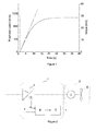
- Figure 1 illustrates an example of a change in the angular speed in response to an applied stepwise torque.
- a combined effect of a moment of inertia of a fan and the torque requirement for a fluid transferred at the angular speed is shown.
- the angular speed increases substantially linearly to a speed of 400 rpm.
- the torque required to transfer the fluid becomes more dominant, and the rate of change of the angular speed is no longer linear.
- Figure 2 illustrates an exemplary apparatus 1 for estimating a change in the mass of a fan impeller.
- the apparatus comprises a frequency converter 2 powering a fan 3.
- the frequency converter 2 supplies power to a fan motor 4 of the fan 3.
- the fan motor 4 rotates a fan impeller 5.
- the frequency converter 2 acts as a means for inducing a torque to the fan impeller 5.
- the apparatus 1 further comprises an estimator 6, which produces a value representing the mass of the fan impeller 5.
- the estimator 6 determines a change in the angular speed of the fan impeller induced by the torque by using the angular speed information provided by the frequency converter 2.
- the estimator 6 then calculates a value for a first parameter representing the present mass of the fan impeller on the basis of a change in the angular speed of the fan impeller and the torque.
- a reference sequence for determining a reference may be executed.
- a value for the second parameter may be set during this sequence.
- a value for a third parameter representing a maximum allowable change in the mass may also be set.
- the reference sequence may, for instance, take place during commissioning or after a fan impeller clean-up.
- a first value of the first parameter determined after a fan has been installed or cleaned may be used as the value of the second parameter.
- the first parameter representing the present mass of the fan impeller can be determined using the method disclosed above.
- a detection sequence is initiated.
- a change in the mass may be determined on the basis of a torque induced to the fan impeller and a change in the angular speed of the fan impeller induced by the torque as disclosed above.
- the difference between the values of the first parameter and the value of the second parameter may be calculated.
- the difference represents a change in the mass of the fan impeller.
- the difference may then be compared with the third parameter, and if the difference exceeds the third parameter, a notification may be issued.
- the first parameter may be compared with the second parameter indicating a maximum limit for the mass of the fan impeller, and, if the first parameter exceeds the second parameter, a notification may be issued.
- Figure 3 illustrates an exemplary flow chart for the operation of the apparatus of Figure 2 .
- the reference sequence and the detection sequence share some of the steps in Figure 3 .
- step 13 the value of the first parameter representing the present mass is determined.
- a time derivate of the angular speed may be calculated on the basis of the angular speed.
- the samples may be filtered in order to remove possible noise and clearly erroneous samples.
- the filtering may, for instance, be implemented using a 20-point median filter having a time period of 0.2 s.
- a new data set where the angular speed is between a lower limit and an upper limit may be formed out of the filtered samples.
- a slope k representing the time derivate of the angular speed can then be calculated from the data set by using, for instance, the method of the sum of least squares.
- the value for the first parameter may be determined on the basis of the slope k. Since the torque follows a known step pattern, the value of the slope k may itself be used as an indicator of the mass of the fan impeller. In other words, the first and second parameter may be represented in the form of the time derivate of the angular speed. Slope k is inversely proportional to the contamination build-up. As the amount of a contaminant starts to build up, the value of k decreases.
- the disclosed method may also be used to detect a decrease in the mass of the fan impeller.
- a contaminant may grind the fan impeller, causing the mass of the fan impeller to decrease. This can be seen as a reduction in the moment of inertia of the fan impeller.
- a loss in the mass may be seen as an increase in the value of the slope k , or as a decrease in the values of the moment of inertia J or the mass m.
- step 14 If the value of the first parameter is calculated for the first time, for instance, after a fan has been installed or cleaned, the value is set as the value of the second parameter in step 15. The reference sequence is now finished and the detection sequence begins.
- the watchdog of the apparatus may, for instance, send a warning message to the user that there is a contamination build-up in the fan, which causes the change in the mass of the fan impeller to exceed its maximum allowable limit.
- the mass increases were 0 g, 50 g, 104 g and 151 g.
- the moments of inertia caused by the added masses were 0 kgm 2 , 0.005 kgm 2 , 0.010 kgm 2 , and 0.015 kgm 2 , respectively.
- the inertia of the fan impeller used was 1.26 kgm 2 according to the manufacturer.
- increases of the moment of inertia of the fan impeller were 0%, 0.4%, 0.8%, and 1.2%, respectively.
- the tests were done using different valve positions and torque reference values.
- the results indicate that the torque reference used for the acceleration of the fan impeller did not have a significant effect on the analysis results for indicating a change ( ⁇ J / J 0g ) in the moment of inertia.
- the torque reference is not constrained to a certain level when using the disclosed method.
- the effect of the fan operating point may be minimized by using the same upper and lower angular speed limits in the reference sequence and the detection sequence.
- the estimation of the increase in the mass was quite accurate, as shown in Table 4.
- the relatively accurate result may, in part, be a consequence of the assumption that all of the mass is at a certain distance from the axis of rotation. In real applications, the situation may not be as simple.
Abstract
Description
- The present invention relates to a fan and particularly to detecting a change in the mass of a fan impeller.
- Fans are widely used in a large variety of applications and operating conditions. They are often used for ventilating contaminated air and exhaust of combustion gases. In these applications, small particles, such as soot, may accumulate on the fan impeller and gradually cause a decrease in the efficiency of the fan.
- Contamination of the fan impeller can be seen as a cause for some fan system failures. The mass of the impeller increases as foreign particles get stuck on the fan impeller. Because of vibration or careless maintenance, part of the additional mass may fall off, causing unbalance in the fan impeller. If the unbalance is not detected and corrected early enough, a fan failure may occur because of the higher vibration. Such a failure may lead to production losses or even to hazards to personnel. Thus, it may be important to detect contamination build-ups.
- Typically, contamination build-ups in fan impellers are visually detected or, if the contamination causes imbalance in the impeller, by vibration measurements. However, these methods require additional instrumentation or visual/manual inspection of the fan. Thus, they increase the operating cost of the application comprising fan impellers.
- An object of the present invention is to provide a method and an apparatus for implementing the method so as to solve the above problems. The objects of the invention are achieved by a method and an apparatus, which are characterized by what is stated in the independent claims. The preferred embodiments of the invention are disclosed in the dependent claims.
- A change in the mass of a fan impeller can be detected by using a method which is based on the idea that the moment of inertia of the fan increases as contaminants increase the mass of the fan impeller. The moment of inertia is inversely proportional to the derivate of the angular speed of the fan impeller as a function of time when a torque is applied to the fan. In other words, as the moment of inertia of the fan increases, the derivate of the angular speed of the fan decreases.
- A fluid transferred by the fan may have an effect on the measurement. Thus, in order to avoid the effect of the fluid transferred to the measurement, the derivate may be determined by using a low angular speed range where the torque required by the moment of inertia of the fan is much greater than the torque required to transfer the fluid.
- A frequency converter may be utilized in detecting the build-up of additional mass. By using a frequency converter powering the fan, it is possible to detect a build-up of a contaminant or contaminants without extra instrumentation also when the fan is otherwise operating in a normal and healthy state.
- In the following, the disclosure will be described in greater detail by means of exemplary embodiments with reference to the attached drawings, in which
-
Figure 1 illustrates an example of a change in angular speed in response to an applied stepwise torque; -
Figure 2 illustrates an exemplary apparatus for estimating a change in the mass of a fan impeller; and -
Figure 3 illustrates an exemplary flow chart for the operation of the apparatus ofFigure 2 . - A relationship between a torque T, a moment of inertia J, and an angular speed ω can be represented in the following form:

- The mass of a fan impeller can be estimated using
Equation 1, if the torque T and the time derivate of an angular speed induced by the torque are known. - For instance, a known torque T may first be induced to the fan impeller. The torque T may be induced on the basis of a set torque reference pattern. A change in an angular speed ω of the fan impeller induced by the torque may then be determined, for instance, by measuring. The change may, for instance, be represented in a form of time derivate of the angular speed ω. The change of the angular speed may, for instance, be calculated on the basis of a measured angular speed ω. Alternatively, the time derivate of the angular speed can be determined, for instance, by directly measuring an acceleration induced by the torque.
- A moment of inertia J can be determined on the basis of the torque T and the change in the angular speed ω. Because a moment of inertia is proportional to a mass, the mass of the fan impeller may be represented in the form of the moment of inertia J.
-
Equation 1 may be used to determine a change in the mass caused by, for instance, a contaminant accumulating on a fan impeller. A value for a first parameter representing the present mass of the fan impeller may be determined on the basis of the torque and the change in the angular speed. The torque may be measured or estimated. A torque reference of a controller producing the torque can also be used to represent an estimate of the torque. The change in the mass may then be determined on the basis of the first parameter and a second parameter representing a reference mass of the fan impeller. - For instance, the value of the first parameter may be sequentially updated and compared to a set value of the second parameter. In this case, the second parameter may be used to indicate a maximum limit for the mass of the fan impeller. If the value of the first parameter exceeds the second parameter, a notification may be issued.
- Alternatively, a first value of the first parameter determined after a fan has been installed or cleaned may be used as a reference value with which first parameter values are later on compared. The first value of the first parameter may be set as the value of the second parameter. The first parameter may then be sequentially updated, and the difference between the values of the first parameter and the second parameter may be calculated. A value for a third parameter representing a maximum allowable change in the mass can be set.
- A change in the mass determined on the basis of the first parameter and the second parameter may then be compared with the third parameter, and if the change in the mass exceeds the third parameter, a notification may be issued.
- The change in the mass may, in some embodiments of the disclosed method, be represented in the form of a change ΔJ in the moment of inertia. In other words, the first parameter and the second parameter are represented in the form of a moment of inertia J.
- The first parameter, the second parameter, and the third parameter may also be represented directly by a mass. In other words, a change Δm in the mass that has affected the moment of inertia can be calculated in weight units. For instance, if a contaminant on the fan impeller is assumed to accumulate at a certain distance r from the axis of rotation, the change Δm in mass can be estimated as follows:

where ΔJ is a change in the moment of inertia. - In more generic terms, if a distribution of a contaminant on the fan impeller can be predicted, a similar method can be used to estimate a change Δm in the mass caused by the contaminant. The total moment of inertia can be seen as an arithmetic sum of individual moments of inertia. When the distribution of these individual moments of inertia is known, the change Δm in the mass can be estimated.
- In an embodiment of the disclosed method, a torque T with a step pattern may be used in order to determine the time derivate of the angular speed ω. In other words, the torque T is induced to the fan impeller by using a constant torque reference. When the torque T has a step-like pattern in a time-domain, the angular speed ω can be written as a function of time in the following form:

where t is time, ω0 is the initial angular speed, and J is a moment of inertia. It can be seen fromEquations - The total moment of inertia is an arithmetic sum of individual moments of inertia. Thus, if two separate measurements of k have been made, the change in the moment of inertia can be calculated by:

where T 1 and T 2 are torque steps used for the measurement of k 1 and k 2, respectively. - When not taking into account the effect of a transferred fluid, a moment of inertia Jfan of a fan can be seen as a sum of two components: an initial moment of inertia Jimpeller of a clean fan impeller and moment of inertia Jcontaminants caused by a contaminant or contaminants on the fan blades:

- However, a fluid transferred through the fan may have a significant effect on the moment of inertia. At higher angular speeds, a total torque requirement for achieving a certain angular speed may be dominated by the torque required to transfer the fluid. The torque requirement for transferring the fluid may have an effect on the time derivate of the angular speed while the moment of inertia of the fan stays constant. In some embodiments, a linear increase according to
Equation 3 may be only detectable at low angular speeds where the total torque requirement is dominated by the moment of inertia Jimpeller of the fan impeller. -
Figure 1 illustrates an example of a change in the angular speed in response to an applied stepwise torque. InFigure 1 , a combined effect of a moment of inertia of a fan and the torque requirement for a fluid transferred at the angular speed is shown. The angular speed increases substantially linearly to a speed of 400 rpm. At higher speeds, the torque required to transfer the fluid becomes more dominant, and the rate of change of the angular speed is no longer linear. - In order to minimize the effect of the torque requirement for the fluid transfer from the analysis, an upper limit for an angular speed range used in the estimation may, for instance, be defined such that 90 to 95% of the total torque requirement is caused by the moment of inertia of the fan impeller. An approximation of a ratio RT between the torque required by the moment of inertia of the fan and the torque required for transferring the fluid can be calculated for instance as follows

where n is an instantaneous angular speed and nfinal is a final angular speed acquired by a constant torque used. On the basis ofEquation 6, the upper angular speed limit nlimit,upper may be calculated as follows
Correspondingly, there may be a lower limit for the angular speed used in the analysis because angular speed estimates provided, for instance, by a frequency converter without a speed sensor on the motor shaft may be erroneous at a speed near to zero. At near to zero speeds, static friction may cause nonlinearity in the derivate of the angular speed. For these reasons, the lower limit may, for instance, be defined such that angular speeds of 3% or less of the final speed are excluded from the estimation. In this manner, unwanted physical phenomena and erroneous speed estimates may be minimized in the analysis. Since a required lower limit can be affected by the angular speed method used in the frequency converter, a scalar controlled frequency may, for instance, require a higher value than 3% of the final speed for the lower limit. - For an exemplary fan arrangement having a final angular speed of 1500 rpm, an upper angular speed limit of 335 rpm can be calculated using
Equation 6 with a 95% criterion for RT . In other words, the upper limit is an angular speed on which 95% of a total torque requirement is caused by the moment of inertia. A lower limit of 45 rpm may be calculated on the basis of the criterion of 3% of the final angular speed (1500 rpm) of the fan impeller reached by using a constant torque. - In the previous embodiment, a step pattern was used for the torque reference in order to achieve a constant time derivate of the angular speed in a certain angular speed region. However, other patterns for the torque may also be used. For instance,
Equation 1 can be modified to the form:
-
Figure 2 illustrates anexemplary apparatus 1 for estimating a change in the mass of a fan impeller. The apparatus comprises afrequency converter 2 powering afan 3. Thefrequency converter 2 supplies power to afan motor 4 of thefan 3. Thefan motor 4 rotates afan impeller 5. In other words, thefrequency converter 2 acts as a means for inducing a torque to thefan impeller 5. - A torque applied to the
fan impeller 5 causes a change in the angular speed of thefan impeller 5. InFigure 2 , thefrequency converter 2 can be used for determining the angular speed. Thefrequency converter 2 may, for instance, estimate the angular speed on the basis of fan motor currents. - In
Figure 2 , theapparatus 1 further comprises anestimator 6, which produces a value representing the mass of thefan impeller 5. Theestimator 6 determines a change in the angular speed of the fan impeller induced by the torque by using the angular speed information provided by thefrequency converter 2. Theestimator 6 then calculates a value for a first parameter representing the present mass of the fan impeller on the basis of a change in the angular speed of the fan impeller and the torque. - The
apparatus 1 also comprises awatchdog 7, which determines the change in the mass on the basis of the first parameter and a second parameter representing a reference mass of the fan impeller. Thewatchdog 7 may comprise a comparator, which compares the difference between the first parameter and the second parameter to a third parameter representing a maximum allowable change in mass. The watchdog may further comprise means for sending a warning message to the user in case the change in the mass exceeds the maximum allowable change in the mass. Theestimator 6 and thewatchdog 7 may, for instance, be implemented as a part of thefrequency converter 2. - In
Figure 2 , thefrequency converter 2 provides the torque and the angular speed information for theestimator 6. However, the torque and the angular speed information may also be provided by other means. For instance, thefan 3 may comprise an angular speed sensor. In some embodiments, the torque between the fan motor and the fan impeller may also be directly measured by a torque sensor. Depending on the implementation, a mass of the fan motor may be included to the mass estimate of the fan impeller. - The operation of the
apparatus 1 may be divided into two sequences. - First, a reference sequence for determining a reference may be executed. A value for the second parameter may be set during this sequence. A value for a third parameter representing a maximum allowable change in the mass may also be set. The reference sequence may, for instance, take place during commissioning or after a fan impeller clean-up. A first value of the first parameter determined after a fan has been installed or cleaned may be used as the value of the second parameter. The first parameter representing the present mass of the fan impeller can be determined using the method disclosed above.
- Second, a detection sequence is initiated. A change in the mass may be determined on the basis of a torque induced to the fan impeller and a change in the angular speed of the fan impeller induced by the torque as disclosed above.
- The difference between the values of the first parameter and the value of the second parameter may be calculated. The difference represents a change in the mass of the fan impeller. The difference may then be compared with the third parameter, and if the difference exceeds the third parameter, a notification may be issued.
- Alternatively, the first parameter may be compared with the second parameter indicating a maximum limit for the mass of the fan impeller, and, if the first parameter exceeds the second parameter, a notification may be issued.
-
Figure 3 illustrates an exemplary flow chart for the operation of the apparatus ofFigure 2 . The reference sequence and the detection sequence share some of the steps inFigure 3 . - In the reference sequence, the third parameter is first initialized in
step 10. The third parameter may, for instance, be set to have a certain maximum change in the mass, represented in weight units. The maximum change in the mass may also be represented in the form of a percentage of the reference mass. - The reference sequence continues by determining the present mass of the
fan impeller 6 insteps - A known torque is induced to the fan impeller on the basis of a set torque reference pattern in
step 11. InFigure 3 , the pattern is a step pattern. In other words, the fan is accelerated from a zero angular speed by using a constant torque reference. - The angular speed of the fan impeller induced by the torque is then be determined in
step 12. The frequency converter may provide an angular speed estimate or the angular speed may be measured using a sensor. The angular speed may be sequentially sampled during the acceleration and the samples may be stored, for instance, in a memory of the apparatus, or, if the apparatus is a part of a frequency converter, in a memory of the frequency converter. - In
step 13, the value of the first parameter representing the present mass is determined. A time derivate of the angular speed may be calculated on the basis of the angular speed. After collecting enough angular speed samples, the samples may be filtered in order to remove possible noise and clearly erroneous samples. The filtering may, for instance, be implemented using a 20-point median filter having a time period of 0.2 s. A new data set where the angular speed is between a lower limit and an upper limit may be formed out of the filtered samples. A slope k representing the time derivate of the angular speed can then be calculated from the data set by using, for instance, the method of the sum of least squares. - Next, the value for the first parameter may be determined on the basis of the slope k. Since the torque follows a known step pattern, the value of the slope k may itself be used as an indicator of the mass of the fan impeller. In other words, the first and second parameter may be represented in the form of the time derivate of the angular speed. Slope k is inversely proportional to the contamination build-up. As the amount of a contaminant starts to build up, the value of k decreases.
- Alternatively, the moment of inertia J or a mass m can be calculated. A change in the moment of inertia and a change in the mass are directly proportional to the contamination build-up. As the amount of the contaminant build up, their values increase.
- The disclosed method may also be used to detect a decrease in the mass of the fan impeller. In some applications, a contaminant may grind the fan impeller, causing the mass of the fan impeller to decrease. This can be seen as a reduction in the moment of inertia of the fan impeller. A loss in the mass may be seen as an increase in the value of the slope k, or as a decrease in the values of the moment of inertia J or the mass m.
- Next, a choice is made in
step 14. If the value of the first parameter is calculated for the first time, for instance, after a fan has been installed or cleaned, the value is set as the value of the second parameter instep 15. The reference sequence is now finished and the detection sequence begins. - The detection sequence starts back from
step 11, and continues again to step 14. As the value of the first parameter is not calculated for the first time,step 16 is executed after theselection step 15. Instep 16, the difference between the first parameter representing the present mass of the fan impeller and the second parameter representing the reference mass of the fan impeller is calculated. In the followingstep 17, a further choice is made. - If this difference exceeds the value of the third parameter set in
step 10, a notification is issued instep 18. The watchdog of the apparatus may, for instance, send a warning message to the user that there is a contamination build-up in the fan, which causes the change in the mass of the fan impeller to exceed its maximum allowable limit. - If the difference does not exceed the value of the third parameter in
step 17, the detection sequence is repeated fromstep 11. - Laboratory measurements were conducted for an arrangement comprising a radial fan system comprising a
FläktWoods Centripal EU 4 MD 630 radial blower, an ABB induction motor and an ABB ACS M1 frequency converter. The nominal values of the system were as follows:Table 1 Fan Motor Frequency converter Rotational speed (rpm) Power (kW) Flow rate (m3/s) Fan total pressure (Pa) Impeller diameter (mm) Rotational speed (rpm) Power (kW) Current (A) cosϕ Nominal current (A) 1446 7.50 2.90 1190 630 1450 7.5 15.7 0.80 16 - An increase of the mass was simulated by adding weights to the outer edge of the fan impeller. Two identical weights were fastened on opposite sides of the fan impeller in order to ensure balance of the fan impeller.
- The mass increases were 0 g, 50 g, 104 g and 151 g. The moments of inertia caused by the added masses were 0 kgm2, 0.005 kgm2, 0.010 kgm2, and 0.015 kgm2, respectively. The inertia of the fan impeller used was 1.26 kgm2 according to the manufacturer. Thus, increases of the moment of inertia of the fan impeller were 0%, 0.4%, 0.8%, and 1.2%, respectively. The tests were done using different valve positions and torque reference values.
- In the first measurement setup, a 30% torque reference (14.8 N) was used at the start-up. RT was set to 95%. Measurements were conducted using three different valve positions, so the fan was operating at 50%, 100%, and 120% of the nominal flow rate.
- The results are shown in Table 2. Each of the three measurements was repeated three times in order to ensure repeatability of the results. Each row shows the mean and standard deviation of the nine measurements. Change magnitudes Δk and ΔJ were calculated using more accurate values of the mean values of k than what is shown in Table 2. k 0g represents the reference slope and J 0g represents the reference moment of inertia in Table 2.
Table 2 Mass increase (g) Mean of k Standard deviation of k Indicated change in the mean of k (|Δk|=|k-k 0g |) Indicated change in k (Δk/k 0g ) Indicated change in the moment of inertia (Δjlj 0g ) 0 115.4 0.15 0 0.00% 0.00% 50 115.0 0.17 0.4 -0.40% 0.41% 104 114.5 0.10 0.9 -0.80% 0.81% 151 114.1 0.16 1.4 -1.16% 1.17% - The results in Table 2 indicate that a change in the valve position had no significant effect on the estimation of the moment of inertia. The standard deviation remained small compared to the mean value of k. The estimated change in the moment of inertia also remains accurate despite a change in a fan valve operating point.
- In another measurement setup, a 50% torque reference (24.7 Nm) was used. Measurements were conducted using two valve positions. The results shown in Table 3 also indicate that the valve position had no significant
effect on the estimation accuracy. Change magnitudes Δk and ΔJ were calculated using more accurate values of the mean values of k than what is shown in Table 3.Table 3 Mass increase (g) Mean of k Standard deviation of k Indicated change in the mean of k (|Δk|=|k-k 0g |) Inidcated change in k (Δk/k 0g ) Indicated change in the moment of inertia (Δ Jl J0g ) 0 190.5 0.16 0 0.00% 0.00% 50 189.4 0.29 1.1 -0.57% 0.58% 104 189.0 0.27 1.5 -0.80% 0.81% 151 188.2 0.32 2.3 -1.19% 1.20% - The results shown in Table 2 and Table 3 indicate that an increase in the mass of a fan impeller can be detected by using the disclosed method since the mean value of k clearly indicates a notable change in the moment of the inertia of the fan impeller. In addition, the standard deviation of the measurement is smaller than the change of k, which suggests that the results are repeatable.
- The results also indicate that the torque reference used for the acceleration of the fan impeller did not have a significant effect on the analysis results for indicating a change (ΔJ /J0g ) in the moment of inertia. Thus, the torque reference is not constrained to a certain level when using the disclosed method.
- Further, the results seem to indicate that the estimation of the change in the moment of inertia may be maximized by using the same torque reference for the reference sequence and the detection sequence. The effect of the fan operating point may be minimized by using the same upper and lower angular speed limits in the reference sequence and the detection sequence.
- In the laboratory measurements, a change in the mass was also estimated using
Equation 2. The fan impeller had a diameter d of 630 mm. In the estimation, the contaminants (the added weights) were assumed to be accumulated on the edges of the fan blades, thus giving a radius r of approximately half (315 mm) of the fan impeller diameter d. The results of the estimation of the mass increase are shown in Table 4.Table 4 Torque reference 30%Torque reference 50% Mass increase (g) Estimated mass increase (g) Estimation error (g) Mass increase (g) Estimated mass increase (g) Estimation error (g) 0 0 0 0 0 0 50 50 0 50 72 12 104 100 -4 104 101 -3 151 144 -7 151 150 -1 - The estimation of the increase in the mass was quite accurate, as shown in Table 4. The relatively accurate result may, in part, be a consequence of the assumption that all of the mass is at a certain distance from the axis of rotation. In real applications, the situation may not be as simple.
- However, if a typical distribution of accumulating contaminants is well known, it may be possible to achieve results of similar accuracy.
- It will be obvious to a person skilled in the art that the features of the disclosure can be implemented in various ways. The disclosure and its embodiments are not limited to the examples described above but may vary within the scope of the claims.
Claims (14)
- A method for determining a change in a mass of a fan impeller, wherein the method comprises
inducing a torque to the fan impeller,
determining a change in the angular speed of the fan impeller, induced by the torque,
determining, on the basis of the change in the angular speed and the torque, a value for a first parameter representing a present mass of the fan impeller, and
determining the change in the mass on the basis of the first parameter and a second parameter representing a reference mass of the fan impeller. - A method according to claim 1, wherein the method comprises
setting a value for the second parameter,
setting a value for a third parameter representing a maximum allowable change in the mass,
comparing the change in the mass with the third parameter, and
if the change in the mass exceeds the third parameter, issuing a notification. - A method according to claim 1 or 2, wherein the torque is induced to the fan impeller on the basis of a set torque reference pattern, and the change in the angular speed is represented in the form of a time derivate of the angular speed.
- A method according to claim 3, wherein determining the time derivate of the angular speed comprises
determining the angular speed of the fan impeller induced by the torque,
calculating a time derivate of the angular speed on the basis of the angular speed. - A method according to claim 4, wherein determining the angular speed comprises
sequentially sampling the angular speed and storing the angular speed samples, and
filtering the angular speed samples in order to reduce noise and to remove clearly erroneous values. - A method according to any one of claims 3 to 5, wherein calculating the time derivate of the angular speed comprises
forming a new data set out of the filtered samples, wherein the angular speed is between a lower limit and an upper limit,
calculating the time derivate from the new data set by using a method of the sum of least squares. - A method according to claim 6, wherein the upper limit is an angular speed on which 95% of a total torque requirement is caused by the moment of inertia of the fan impeller, and the lower limit is 3% of the final angular speed of the fan impeller reached by using a constant torque.
- A method according to any one of claims 1 to 7, wherein the torque is induced to the fan impeller by using a constant torque reference.
- A method according to any one of claims 2 to 8, wherein issuing the notification comprises
sending a warning signal to an operator of the fan that the change in the mass of the fan impeller has exceeded its maximum allowable limit. - A method according to any one of claims 1 to 9, wherein the first parameter and second parameter are represented in the form of the moment of inertia (J).
- A method according to any one of claims 1 to 9, wherein the first parameter and the second parameter are represented in the form of the time derivate of the angular speed (k).
- A method according to any one of claims 1 to 9, wherein the first parameter and the second parameter are represented by a mass (m).
- An apparatus (1) for determining a change in a mass of a fan impeller (5), wherein the apparatus (1) comprises
means (2) for inducing a torque to the fan impeller (5),
means (6) for determining a change in the angular speed of the fan impeller, induced by the torque,
means (6) for determining, on the basis of the change in the angular speed and the torque, a value for a first parameter representing a present mass of the fan impeller (5), and
means (6) for determining the change in the mass on the basis of the first parameter and a second parameter representing a reference mass of the fan impeller (5). - A frequency converter according to claim 13.
Priority Applications (3)
| Application Number | Priority Date | Filing Date | Title |
|---|---|---|---|
| EP20110179147 EP2565465B1 (en) | 2011-08-29 | 2011-08-29 | Method and apparatus for determining change in mass of fan impeller |
| US13/590,708 US9021876B2 (en) | 2011-08-29 | 2012-08-21 | Method and apparatus for determining change in mass of fan impeller |
| CN201210311172.1A CN102966582B (en) | 2011-08-29 | 2012-08-28 | For determining the method and apparatus of the mass change of draught fan impeller |
Applications Claiming Priority (1)
| Application Number | Priority Date | Filing Date | Title |
|---|---|---|---|
| EP20110179147 EP2565465B1 (en) | 2011-08-29 | 2011-08-29 | Method and apparatus for determining change in mass of fan impeller |
Publications (3)
| Publication Number | Publication Date |
|---|---|
| EP2565465A1 true EP2565465A1 (en) | 2013-03-06 |
| EP2565465A9 EP2565465A9 (en) | 2013-06-05 |
| EP2565465B1 EP2565465B1 (en) | 2014-12-10 |
Family
ID=44653181
Family Applications (1)
| Application Number | Title | Priority Date | Filing Date |
|---|---|---|---|
| EP20110179147 Active EP2565465B1 (en) | 2011-08-29 | 2011-08-29 | Method and apparatus for determining change in mass of fan impeller |
Country Status (3)
| Country | Link |
|---|---|
| US (1) | US9021876B2 (en) |
| EP (1) | EP2565465B1 (en) |
| CN (1) | CN102966582B (en) |
Cited By (2)
| Publication number | Priority date | Publication date | Assignee | Title |
|---|---|---|---|---|
| EP3199813A1 (en) * | 2016-01-28 | 2017-08-02 | ABB Technology Oy | Load/unload control method for compressor system |
| CN111431454A (en) * | 2020-04-28 | 2020-07-17 | 中山大洋电机股份有限公司 | Method for judging reliability of estimated rotating speed of position-sensorless vector control permanent magnet motor |
Families Citing this family (4)
| Publication number | Priority date | Publication date | Assignee | Title |
|---|---|---|---|---|
| CN110568950B (en) * | 2018-06-05 | 2023-08-01 | 鸿富锦精密工业(深圳)有限公司 | TFT substrate and touch display panel |
| CN110735812B (en) * | 2019-09-05 | 2021-01-15 | 宁波方太厨具有限公司 | Control method for avoiding manual maintenance of impeller of range hood |
| DE102020133000A1 (en) * | 2020-12-10 | 2022-06-15 | Ebm-Papst Landshut Gmbh | Method for determining and detecting states, changes in state and faults in a turbomachine |
| CN115441796A (en) * | 2021-06-02 | 2022-12-06 | 台达电子工业股份有限公司 | Speed control method based on load torque-rotational inertia self-learning model |
Citations (4)
| Publication number | Priority date | Publication date | Assignee | Title |
|---|---|---|---|---|
| EP0476588A1 (en) * | 1990-09-21 | 1992-03-25 | Hitachi, Ltd. | A method and apparatus for computing moment of inertia in a motor speed controller, and a speed control method and apparatus for motor |
| JP2002267249A (en) * | 2001-03-09 | 2002-09-18 | Sharp Corp | Fluid-delivering device |
| EP1388732A1 (en) * | 2002-08-08 | 2004-02-11 | Dr. Johannes Heidenhain GmbH | Method for determining the moment of inertia of an electromotive drive system |
| EP2135660A1 (en) * | 2008-06-17 | 2009-12-23 | Atlantic Climatisation et Ventilation | Method for determining the clogging level of air filters |
Family Cites Families (9)
| Publication number | Priority date | Publication date | Assignee | Title |
|---|---|---|---|---|
| SU488143A1 (en) * | 1973-06-22 | 1975-10-15 | Предприятие П/Я А-1891 | Acceleration sensor |
| GB2090340B (en) * | 1980-12-31 | 1984-07-18 | Sueddeutsche Kuehler Behr | Radial fan wheel |
| SU1059466A1 (en) * | 1982-05-10 | 1983-12-07 | Институт Проблем Машиностроения Ан Усср | Device for testing axial fan blades |
| JPS6188780A (en) * | 1984-10-08 | 1986-05-07 | Hitachi Ltd | Control constant setting method for speed controller |
| CN1021928C (en) * | 1987-04-10 | 1993-08-25 | 广东机械学院 | Instrument with electronic brain for mechanical property of asynchronous motor |
| JP3632748B2 (en) * | 2000-03-21 | 2005-03-23 | 日立プラント建設株式会社 | Method for evaluating solid surface adsorption of pollutants |
| DE102009022720B4 (en) * | 2009-05-26 | 2020-11-05 | Sew-Eurodrive Gmbh & Co Kg | Fan arrangement |
| CN101749256B (en) * | 2010-01-08 | 2013-11-13 | 浙江大学 | Large axial flow fan unbalance recognition method based on auto-correlation |
| JP5168342B2 (en) * | 2010-11-05 | 2013-03-21 | パナソニック株式会社 | Ceiling fan safety device |
-
2011
- 2011-08-29 EP EP20110179147 patent/EP2565465B1/en active Active
-
2012
- 2012-08-21 US US13/590,708 patent/US9021876B2/en active Active
- 2012-08-28 CN CN201210311172.1A patent/CN102966582B/en active Active
Patent Citations (4)
| Publication number | Priority date | Publication date | Assignee | Title |
|---|---|---|---|---|
| EP0476588A1 (en) * | 1990-09-21 | 1992-03-25 | Hitachi, Ltd. | A method and apparatus for computing moment of inertia in a motor speed controller, and a speed control method and apparatus for motor |
| JP2002267249A (en) * | 2001-03-09 | 2002-09-18 | Sharp Corp | Fluid-delivering device |
| EP1388732A1 (en) * | 2002-08-08 | 2004-02-11 | Dr. Johannes Heidenhain GmbH | Method for determining the moment of inertia of an electromotive drive system |
| EP2135660A1 (en) * | 2008-06-17 | 2009-12-23 | Atlantic Climatisation et Ventilation | Method for determining the clogging level of air filters |
Cited By (3)
| Publication number | Priority date | Publication date | Assignee | Title |
|---|---|---|---|---|
| EP3199813A1 (en) * | 2016-01-28 | 2017-08-02 | ABB Technology Oy | Load/unload control method for compressor system |
| US10451052B2 (en) | 2016-01-28 | 2019-10-22 | Abb Schweiz Ag | Load/unload control method for compressor system |
| CN111431454A (en) * | 2020-04-28 | 2020-07-17 | 中山大洋电机股份有限公司 | Method for judging reliability of estimated rotating speed of position-sensorless vector control permanent magnet motor |
Also Published As
| Publication number | Publication date |
|---|---|
| EP2565465B1 (en) | 2014-12-10 |
| US9021876B2 (en) | 2015-05-05 |
| US20130047724A1 (en) | 2013-02-28 |
| EP2565465A9 (en) | 2013-06-05 |
| CN102966582B (en) | 2015-09-30 |
| CN102966582A (en) | 2013-03-13 |
Similar Documents
| Publication | Publication Date | Title |
|---|---|---|
| EP2565465B1 (en) | Method and apparatus for determining change in mass of fan impeller | |
| EP2620202B1 (en) | Method and apparatus for monitoring air filter condition | |
| CN103376743B (en) | A kind of constant air capacity control of motor and air conditioner draught fan system | |
| US20160281723A1 (en) | Direct power control for constant airflow control | |
| JPH08503042A (en) | Method and apparatus for monitoring the excitation of an axial compressor | |
| JP6154600B2 (en) | Method and apparatus for detecting rotational stall and compressor | |
| US20100068070A1 (en) | Flow control for fluid handling system | |
| EP2541067A2 (en) | Surge estimator | |
| US20150166186A1 (en) | Aircraft air-conditioning heat exchanger contamination detection | |
| US20080083280A1 (en) | Method and Device for Identifying a Damaged Bearing of a Rotating Shaft | |
| EP3055661B1 (en) | A method for determining current eccentricity of rotating rotor and method of diagnostics of eccentricity of rotating rotor | |
| US20130129481A1 (en) | Method for detecting the correct rotational direction of a centrifugal apparatus, and a centrifugal apparatus assembly | |
| CN110762771B (en) | Air conditioner external unit resonance control method and device and air conditioner | |
| EP3810905B1 (en) | Turbine speed detection and use | |
| JP6126896B2 (en) | Air conditioner | |
| EP2469098A1 (en) | Method and device for predicting the instability of an axial compressor | |
| Tamminen et al. | Detection of mass increase in a fan impeller with a frequency converter | |
| CN105136394B (en) | The quickly method and device of processing boiler fan vibration fault | |
| EP2505848B1 (en) | Stall detection in fans utilizing frequency converter | |
| WO2013169508A1 (en) | Exhaust-gas turbocharger | |
| EP2589813A1 (en) | Entrapment detection for variable speed pump system using load coefficient | |
| WO2013159458A1 (en) | Motor and constant air volume control method for air-conditioning fan system | |
| JP2013096284A (en) | Centrifugal type electric blower | |
| JP5985182B2 (en) | Ventilation method of vacuum pump and apparatus equipped with vacuum pump | |
| JPS63134022A (en) | Determination method for clogging of bag filter |
Legal Events
| Date | Code | Title | Description |
|---|---|---|---|
| PUAI | Public reference made under article 153(3) epc to a published international application that has entered the european phase |
Free format text: ORIGINAL CODE: 0009012 |
|
| AK | Designated contracting states |
Kind code of ref document: A1 Designated state(s): AL AT BE BG CH CY CZ DE DK EE ES FI FR GB GR HR HU IE IS IT LI LT LU LV MC MK MT NL NO PL PT RO RS SE SI SK SM TR |
|
| AX | Request for extension of the european patent |
Extension state: BA ME |
|
| 17P | Request for examination filed |
Effective date: 20130821 |
|
| RBV | Designated contracting states (corrected) |
Designated state(s): AL AT BE BG CH CY CZ DE DK EE ES FI FR GB GR HR HU IE IS IT LI LT LU LV MC MK MT NL NO PL PT RO RS SE SI SK SM TR |
|
| GRAP | Despatch of communication of intention to grant a patent |
Free format text: ORIGINAL CODE: EPIDOSNIGR1 |
|
| INTG | Intention to grant announced |
Effective date: 20140703 |
|
| GRAS | Grant fee paid |
Free format text: ORIGINAL CODE: EPIDOSNIGR3 |
|
| GRAA | (expected) grant |
Free format text: ORIGINAL CODE: 0009210 |
|
| AK | Designated contracting states |
Kind code of ref document: B1 Designated state(s): AL AT BE BG CH CY CZ DE DK EE ES FI FR GB GR HR HU IE IS IT LI LT LU LV MC MK MT NL NO PL PT RO RS SE SI SK SM TR |
|
| REG | Reference to a national code |
Ref country code: GB Ref legal event code: FG4D |
|
| REG | Reference to a national code |
Ref country code: CH Ref legal event code: EP |
|
| REG | Reference to a national code |
Ref country code: IE Ref legal event code: FG4D |
|
| REG | Reference to a national code |
Ref country code: AT Ref legal event code: REF Ref document number: 700808 Country of ref document: AT Kind code of ref document: T Effective date: 20150115 |
|
| REG | Reference to a national code |
Ref country code: DE Ref legal event code: R096 Ref document number: 602011012073 Country of ref document: DE Effective date: 20150122 |
|
| REG | Reference to a national code |
Ref country code: AT Ref legal event code: MK05 Ref document number: 700808 Country of ref document: AT Kind code of ref document: T Effective date: 20141210 Ref country code: NL Ref legal event code: VDEP Effective date: 20141210 |
|
| REG | Reference to a national code |
Ref country code: NL Ref legal event code: VDEP Effective date: 20141210 |
|
| PG25 | Lapsed in a contracting state [announced via postgrant information from national office to epo] |
Ref country code: NO Free format text: LAPSE BECAUSE OF FAILURE TO SUBMIT A TRANSLATION OF THE DESCRIPTION OR TO PAY THE FEE WITHIN THE PRESCRIBED TIME-LIMIT Effective date: 20150310 Ref country code: LT Free format text: LAPSE BECAUSE OF FAILURE TO SUBMIT A TRANSLATION OF THE DESCRIPTION OR TO PAY THE FEE WITHIN THE PRESCRIBED TIME-LIMIT Effective date: 20141210 Ref country code: ES Free format text: LAPSE BECAUSE OF FAILURE TO SUBMIT A TRANSLATION OF THE DESCRIPTION OR TO PAY THE FEE WITHIN THE PRESCRIBED TIME-LIMIT Effective date: 20141210 |
|
| REG | Reference to a national code |
Ref country code: LT Ref legal event code: MG4D |
|
| PG25 | Lapsed in a contracting state [announced via postgrant information from national office to epo] |
Ref country code: LV Free format text: LAPSE BECAUSE OF FAILURE TO SUBMIT A TRANSLATION OF THE DESCRIPTION OR TO PAY THE FEE WITHIN THE PRESCRIBED TIME-LIMIT Effective date: 20141210 Ref country code: HR Free format text: LAPSE BECAUSE OF FAILURE TO SUBMIT A TRANSLATION OF THE DESCRIPTION OR TO PAY THE FEE WITHIN THE PRESCRIBED TIME-LIMIT Effective date: 20141210 Ref country code: RS Free format text: LAPSE BECAUSE OF FAILURE TO SUBMIT A TRANSLATION OF THE DESCRIPTION OR TO PAY THE FEE WITHIN THE PRESCRIBED TIME-LIMIT Effective date: 20141210 Ref country code: AT Free format text: LAPSE BECAUSE OF FAILURE TO SUBMIT A TRANSLATION OF THE DESCRIPTION OR TO PAY THE FEE WITHIN THE PRESCRIBED TIME-LIMIT Effective date: 20141210 Ref country code: GR Free format text: LAPSE BECAUSE OF FAILURE TO SUBMIT A TRANSLATION OF THE DESCRIPTION OR TO PAY THE FEE WITHIN THE PRESCRIBED TIME-LIMIT Effective date: 20150311 Ref country code: SE Free format text: LAPSE BECAUSE OF FAILURE TO SUBMIT A TRANSLATION OF THE DESCRIPTION OR TO PAY THE FEE WITHIN THE PRESCRIBED TIME-LIMIT Effective date: 20141210 |
|
| PG25 | Lapsed in a contracting state [announced via postgrant information from national office to epo] |
Ref country code: NL Free format text: LAPSE BECAUSE OF FAILURE TO SUBMIT A TRANSLATION OF THE DESCRIPTION OR TO PAY THE FEE WITHIN THE PRESCRIBED TIME-LIMIT Effective date: 20141210 |
|
| PG25 | Lapsed in a contracting state [announced via postgrant information from national office to epo] |
Ref country code: RO Free format text: LAPSE BECAUSE OF FAILURE TO SUBMIT A TRANSLATION OF THE DESCRIPTION OR TO PAY THE FEE WITHIN THE PRESCRIBED TIME-LIMIT Effective date: 20141210 Ref country code: CZ Free format text: LAPSE BECAUSE OF FAILURE TO SUBMIT A TRANSLATION OF THE DESCRIPTION OR TO PAY THE FEE WITHIN THE PRESCRIBED TIME-LIMIT Effective date: 20141210 Ref country code: EE Free format text: LAPSE BECAUSE OF FAILURE TO SUBMIT A TRANSLATION OF THE DESCRIPTION OR TO PAY THE FEE WITHIN THE PRESCRIBED TIME-LIMIT Effective date: 20141210 Ref country code: PT Free format text: LAPSE BECAUSE OF FAILURE TO SUBMIT A TRANSLATION OF THE DESCRIPTION OR TO PAY THE FEE WITHIN THE PRESCRIBED TIME-LIMIT Effective date: 20150410 Ref country code: SK Free format text: LAPSE BECAUSE OF FAILURE TO SUBMIT A TRANSLATION OF THE DESCRIPTION OR TO PAY THE FEE WITHIN THE PRESCRIBED TIME-LIMIT Effective date: 20141210 |
|
| REG | Reference to a national code |
Ref country code: FR Ref legal event code: PLFP Year of fee payment: 5 |
|
| PG25 | Lapsed in a contracting state [announced via postgrant information from national office to epo] |
Ref country code: IS Free format text: LAPSE BECAUSE OF FAILURE TO SUBMIT A TRANSLATION OF THE DESCRIPTION OR TO PAY THE FEE WITHIN THE PRESCRIBED TIME-LIMIT Effective date: 20150410 Ref country code: PL Free format text: LAPSE BECAUSE OF FAILURE TO SUBMIT A TRANSLATION OF THE DESCRIPTION OR TO PAY THE FEE WITHIN THE PRESCRIBED TIME-LIMIT Effective date: 20141210 |
|
| REG | Reference to a national code |
Ref country code: DE Ref legal event code: R097 Ref document number: 602011012073 Country of ref document: DE |
|
| PLBE | No opposition filed within time limit |
Free format text: ORIGINAL CODE: 0009261 |
|
| STAA | Information on the status of an ep patent application or granted ep patent |
Free format text: STATUS: NO OPPOSITION FILED WITHIN TIME LIMIT |
|
| PG25 | Lapsed in a contracting state [announced via postgrant information from national office to epo] |
Ref country code: DK Free format text: LAPSE BECAUSE OF FAILURE TO SUBMIT A TRANSLATION OF THE DESCRIPTION OR TO PAY THE FEE WITHIN THE PRESCRIBED TIME-LIMIT Effective date: 20141210 |
|
| 26N | No opposition filed |
Effective date: 20150911 |
|
| PG25 | Lapsed in a contracting state [announced via postgrant information from national office to epo] |
Ref country code: SI Free format text: LAPSE BECAUSE OF FAILURE TO SUBMIT A TRANSLATION OF THE DESCRIPTION OR TO PAY THE FEE WITHIN THE PRESCRIBED TIME-LIMIT Effective date: 20141210 |
|
| PG25 | Lapsed in a contracting state [announced via postgrant information from national office to epo] |
Ref country code: MC Free format text: LAPSE BECAUSE OF FAILURE TO SUBMIT A TRANSLATION OF THE DESCRIPTION OR TO PAY THE FEE WITHIN THE PRESCRIBED TIME-LIMIT Effective date: 20141210 Ref country code: LU Free format text: LAPSE BECAUSE OF FAILURE TO SUBMIT A TRANSLATION OF THE DESCRIPTION OR TO PAY THE FEE WITHIN THE PRESCRIBED TIME-LIMIT Effective date: 20150829 |
|
| REG | Reference to a national code |
Ref country code: CH Ref legal event code: PL |
|
| PG25 | Lapsed in a contracting state [announced via postgrant information from national office to epo] |
Ref country code: LI Free format text: LAPSE BECAUSE OF NON-PAYMENT OF DUE FEES Effective date: 20150831 Ref country code: CH Free format text: LAPSE BECAUSE OF NON-PAYMENT OF DUE FEES Effective date: 20150831 |
|
| PG25 | Lapsed in a contracting state [announced via postgrant information from national office to epo] |
Ref country code: BE Free format text: LAPSE BECAUSE OF FAILURE TO SUBMIT A TRANSLATION OF THE DESCRIPTION OR TO PAY THE FEE WITHIN THE PRESCRIBED TIME-LIMIT Effective date: 20141210 |
|
| REG | Reference to a national code |
Ref country code: IE Ref legal event code: MM4A |
|
| PG25 | Lapsed in a contracting state [announced via postgrant information from national office to epo] |
Ref country code: IE Free format text: LAPSE BECAUSE OF NON-PAYMENT OF DUE FEES Effective date: 20150829 |
|
| REG | Reference to a national code |
Ref country code: FR Ref legal event code: PLFP Year of fee payment: 6 |
|
| PG25 | Lapsed in a contracting state [announced via postgrant information from national office to epo] |
Ref country code: MT Free format text: LAPSE BECAUSE OF FAILURE TO SUBMIT A TRANSLATION OF THE DESCRIPTION OR TO PAY THE FEE WITHIN THE PRESCRIBED TIME-LIMIT Effective date: 20141210 |
|
| PG25 | Lapsed in a contracting state [announced via postgrant information from national office to epo] |
Ref country code: HU Free format text: LAPSE BECAUSE OF FAILURE TO SUBMIT A TRANSLATION OF THE DESCRIPTION OR TO PAY THE FEE WITHIN THE PRESCRIBED TIME-LIMIT; INVALID AB INITIO Effective date: 20110829 Ref country code: SM Free format text: LAPSE BECAUSE OF FAILURE TO SUBMIT A TRANSLATION OF THE DESCRIPTION OR TO PAY THE FEE WITHIN THE PRESCRIBED TIME-LIMIT Effective date: 20141210 Ref country code: BG Free format text: LAPSE BECAUSE OF FAILURE TO SUBMIT A TRANSLATION OF THE DESCRIPTION OR TO PAY THE FEE WITHIN THE PRESCRIBED TIME-LIMIT Effective date: 20141210 |
|
| PG25 | Lapsed in a contracting state [announced via postgrant information from national office to epo] |
Ref country code: CY Free format text: LAPSE BECAUSE OF FAILURE TO SUBMIT A TRANSLATION OF THE DESCRIPTION OR TO PAY THE FEE WITHIN THE PRESCRIBED TIME-LIMIT Effective date: 20141210 |
|
| REG | Reference to a national code |
Ref country code: FR Ref legal event code: PLFP Year of fee payment: 7 |
|
| PG25 | Lapsed in a contracting state [announced via postgrant information from national office to epo] |
Ref country code: TR Free format text: LAPSE BECAUSE OF FAILURE TO SUBMIT A TRANSLATION OF THE DESCRIPTION OR TO PAY THE FEE WITHIN THE PRESCRIBED TIME-LIMIT Effective date: 20141210 |
|
| PG25 | Lapsed in a contracting state [announced via postgrant information from national office to epo] |
Ref country code: MK Free format text: LAPSE BECAUSE OF FAILURE TO SUBMIT A TRANSLATION OF THE DESCRIPTION OR TO PAY THE FEE WITHIN THE PRESCRIBED TIME-LIMIT Effective date: 20141210 |
|
| REG | Reference to a national code |
Ref country code: FR Ref legal event code: PLFP Year of fee payment: 8 |
|
| REG | Reference to a national code |
Ref country code: GB Ref legal event code: 732E Free format text: REGISTERED BETWEEN 20180823 AND 20180829 |
|
| REG | Reference to a national code |
Ref country code: DE Ref legal event code: R081 Ref document number: 602011012073 Country of ref document: DE Owner name: ABB SCHWEIZ AG, CH Free format text: FORMER OWNER: ABB OY, HELSINKI, FI |
|
| PG25 | Lapsed in a contracting state [announced via postgrant information from national office to epo] |
Ref country code: AL Free format text: LAPSE BECAUSE OF FAILURE TO SUBMIT A TRANSLATION OF THE DESCRIPTION OR TO PAY THE FEE WITHIN THE PRESCRIBED TIME-LIMIT Effective date: 20141210 |
|
| PGFP | Annual fee paid to national office [announced via postgrant information from national office to epo] |
Ref country code: IT Payment date: 20230825 Year of fee payment: 13 Ref country code: GB Payment date: 20230822 Year of fee payment: 13 Ref country code: FI Payment date: 20230821 Year of fee payment: 13 |
|
| PGFP | Annual fee paid to national office [announced via postgrant information from national office to epo] |
Ref country code: FR Payment date: 20230824 Year of fee payment: 13 Ref country code: DE Payment date: 20230821 Year of fee payment: 13 |