EP2135660A1 - Method for determining the clogging level of air filters - Google Patents
Method for determining the clogging level of air filters Download PDFInfo
- Publication number
- EP2135660A1 EP2135660A1 EP09290252A EP09290252A EP2135660A1 EP 2135660 A1 EP2135660 A1 EP 2135660A1 EP 09290252 A EP09290252 A EP 09290252A EP 09290252 A EP09290252 A EP 09290252A EP 2135660 A1 EP2135660 A1 EP 2135660A1
- Authority
- EP
- European Patent Office
- Prior art keywords
- air flow
- current
- drift
- value
- clogging
- Prior art date
- Legal status (The legal status is an assumption and is not a legal conclusion. Google has not performed a legal analysis and makes no representation as to the accuracy of the status listed.)
- Granted
Links
Images


Classifications
-
- F—MECHANICAL ENGINEERING; LIGHTING; HEATING; WEAPONS; BLASTING
- F04—POSITIVE - DISPLACEMENT MACHINES FOR LIQUIDS; PUMPS FOR LIQUIDS OR ELASTIC FLUIDS
- F04D—NON-POSITIVE-DISPLACEMENT PUMPS
- F04D29/00—Details, component parts, or accessories
- F04D29/70—Suction grids; Strainers; Dust separation; Cleaning
- F04D29/701—Suction grids; Strainers; Dust separation; Cleaning especially adapted for elastic fluid pumps
-
- F—MECHANICAL ENGINEERING; LIGHTING; HEATING; WEAPONS; BLASTING
- F04—POSITIVE - DISPLACEMENT MACHINES FOR LIQUIDS; PUMPS FOR LIQUIDS OR ELASTIC FLUIDS
- F04D—NON-POSITIVE-DISPLACEMENT PUMPS
- F04D27/00—Control, e.g. regulation, of pumps, pumping installations or pumping systems specially adapted for elastic fluids
- F04D27/001—Testing thereof; Determination or simulation of flow characteristics; Stall or surge detection, e.g. condition monitoring
-
- F—MECHANICAL ENGINEERING; LIGHTING; HEATING; WEAPONS; BLASTING
- F24—HEATING; RANGES; VENTILATING
- F24F—AIR-CONDITIONING; AIR-HUMIDIFICATION; VENTILATION; USE OF AIR CURRENTS FOR SCREENING
- F24F11/00—Control or safety arrangements
- F24F11/70—Control systems characterised by their outputs; Constructional details thereof
- F24F11/72—Control systems characterised by their outputs; Constructional details thereof for controlling the supply of treated air, e.g. its pressure
- F24F11/74—Control systems characterised by their outputs; Constructional details thereof for controlling the supply of treated air, e.g. its pressure for controlling air flow rate or air velocity
- F24F11/77—Control systems characterised by their outputs; Constructional details thereof for controlling the supply of treated air, e.g. its pressure for controlling air flow rate or air velocity by controlling the speed of ventilators
-
- F—MECHANICAL ENGINEERING; LIGHTING; HEATING; WEAPONS; BLASTING
- F24—HEATING; RANGES; VENTILATING
- F24F—AIR-CONDITIONING; AIR-HUMIDIFICATION; VENTILATION; USE OF AIR CURRENTS FOR SCREENING
- F24F2110/00—Control inputs relating to air properties
- F24F2110/40—Pressure, e.g. wind pressure
-
- Y—GENERAL TAGGING OF NEW TECHNOLOGICAL DEVELOPMENTS; GENERAL TAGGING OF CROSS-SECTIONAL TECHNOLOGIES SPANNING OVER SEVERAL SECTIONS OF THE IPC; TECHNICAL SUBJECTS COVERED BY FORMER USPC CROSS-REFERENCE ART COLLECTIONS [XRACs] AND DIGESTS
- Y02—TECHNOLOGIES OR APPLICATIONS FOR MITIGATION OR ADAPTATION AGAINST CLIMATE CHANGE
- Y02B—CLIMATE CHANGE MITIGATION TECHNOLOGIES RELATED TO BUILDINGS, e.g. HOUSING, HOUSE APPLIANCES OR RELATED END-USER APPLICATIONS
- Y02B30/00—Energy efficient heating, ventilation or air conditioning [HVAC]
- Y02B30/70—Efficient control or regulation technologies, e.g. for control of refrigerant flow, motor or heating
Definitions
- the present invention relates to the regulation of air flow in ventilation installations comprising extraction columns or air insufflation each serving several premises.
- Such an installation comprises a circulating unit of air by means of a motor-fan housed in a box usually placed on the terrace of a building whose apartments are served by columns of arrival and / or suction air.
- each apartment can be equipped with a dual flow cabinet, that is to say, with cross flows between incoming fresh air and stale air that is discharged into the suction column.
- the motor-fan comprises an upstream filter and, likewise, each apartment cabinet comprises a pair of upstream filters, that is to say an apartment input filter, at the local output of the column of arrival, and an apartment exit filter, at the connection between an exhaust duct of the apartment and the cabinet.
- FR-A-2,689,784 discloses a device for detecting fouling of an air filter located in a duct of an air treatment installation operating at constant or variable air flow rate. This device makes it possible to detect the clogging of the filter by the comparative treatment of flow velocity measurements, on the one hand, of the flow rate passing through the filter itself, and on the other hand of the flow rate established in a small auxiliary duct established in bypass filter.
- the present invention aims at providing a solution to the above-mentioned problem of monitoring the state of fouling, or clogging, of the inlet and / or outlet air filters of respective premises.
- the initial moment is arbitrary. Preferably, this will be the time of commissioning the installation. However, in general, we can provide an initial moment "sliding" to monitor the status of the installation over the replacement or cleaning of some filters.
- the invention thus makes it possible, over time, to follow the overall clogging corrugations of the installation, that is to say, on the one hand, the progressive clogging of all the filters, each filter having its own speed. evolution of its clogging, depending on the pollution of the air passing through and the opening time of the corresponding mouth, and on the other hand, the sudden drop in clogging of the mouths or boxes of which user has cleaned or replaced the filter.
- the initial and current times are chosen at a time of the day when the need for flow is stable.
- the initial and current instants can be chosen at night, since the flow requirement for the installation is then substantially constant from one day to the next. For example, by choosing the initial time and current during the night, the need for flow at these times may be equal to the minimum flow of the installation, because no occupant then requires a ventilation rate.
- the invention can be applied to any fluid network, that is to say gas or liquid.
- the operating parameters making it possible to ensure the flow rate considered are advantageously chosen from: the (de) pressure that the fan must provide, the electrical power of the fan drive motor, the output torque of the motor shaft , the intensity of the current consumed by the engine or the frequency of rotation imposed on the engine.
- the drift is measured for, in step d), to estimate a level of clogging drift, according to a law increasing with the drift measured.
- said levels of clogging drift are memorized over time, thereby establishing a temporal prediction table of the evolution of the clogging level, and, subsequently, using the prediction table for making said estimate of the level of clogging drift.
- the table can be established on a first period of operation of the installation, then extrapolate the evolution curve of the clogging thus established, or the table can be established from another installation of the same type, older, so to have the said curve over a long period, so without the need for extrapolation.
- one compares current conditions of effective environment of use of the filters with homologous conditions having existed at the time of the establishment of the prediction table, and one dilates, respectively condenses, a scale of time of the prediction table according to whether the actual environment conditions are less hard, respectively harder, than those associated with the prediction table.
- the clogging information can be used to determine a periodicity value of interventions to be expected for filter replacement.
- the clogging information is advantageous to use to adjust the operating conditions of the installation, that is to say maintain the required performance. Indeed, in the absence of adjustments, it would be necessary to take a a large margin of safety to tolerate clogging, this margin of safety representing a surplus of electricity consumption, which would have its reason to be at the end of the cycle, that is to say when the clogging level of the filters has reached the allowable limit.
- the determination of the information relating to the clogging thus constitutes a first phase, of estimating the state of clogging of the installation, so that, in a second phase, the latter itself determines new operating conditions that are perfectly adapted. new sealing conditions.
- the installation is thus self-adaptive, it is therefore unnecessary to provide a large margin of safety with respect to the (de) pressure that must ensure the fan, that is to say, the power of it.
- provision may be made to correct a control curve of the fan by applying a setpoint drift in a direction according to said drift direction clogging.
- the setpoint curve specifying a determined setpoint pressure for any airflow, the amplitude of the setpoint drift, of pressure is of the form: or is a pressure drop value measured in a said filter for an air flow Qm, and Q BL is a maximum individual air flow value expected for a pipe mouth, ie a maximum air flow mouth with respect to the others.
- the setpoint curve specifying a set air flow, the amplitude of the setpoint drift, of pressure is of the form: or Plmin is a current value of pressure to ensure the set air flow, Pmin is an initial value of pressure to ensure the set air flow, Q B is, as above, a maximum individual air flow value expected for a pipe mouth, and Qmin is a minimum Q airflow value expected for installation.
- the setpoint curve can be corrected by adding a function of the amplitude value of the setpoint drift as calculated above, this function being furthermore increasing with the value of instantaneous airflow Q to be ensured.
- the value of pressure drift is indeed a value which, according to the two preceding formulas, is normalized to a maximum value, to satisfy any need for maximum air flow.
- this maximum correction can be tempered when the actual need for air flow is lower.
- the correction can, for example, follow a quadratic law with the real air flow, to better compensate the pressure losses.
- the drift level is compared to a high threshold, permissible drift, and an alarm is generated if the high threshold is reached.
- the corresponding pressure drop in the filters limits the increase in the air flow rate in the event of a (de) pressure increase stimulus.
- the installation has a signature, response to stimuli increase (de) pressure, which weakens, since the air flow is clamped by clogging.
- the pressure variation is standardized to the same predetermined value at the various instants (x, y) and the value of variation of air flow is taken into account as a value of said slope.
- the stimulus is produced by the shift of the value of a fan operation control parameter, constituting the said associated parameter, for example the electric power of the motor. fan drive or the frequency of rotation imposed on it.
- the said drift measurement corresponds for example to a measurement of an amplitude of the said sensitivity, represented by an amplitude of the said induced variation of the associated parameter.
- the stimulus can be natural, that is to say, correspond to the opening or closing of a mouth by a user. It can also be caused by a manager of the installation, that is to say a person or an electronic system controlling the fan.
- the stimulus created at the "downstream" service parameter of the installation ie the sufficient airflow service to be provided to the users, induces a modification of at least an "upstream” parameter, making it possible to ensure the desired value of the downstream parameter, of the air flow, this modified upstream parameter being able, in the two cases described above, to be the (de) pressure produced by the fan or else the driving power of it.
- the standard mouth If, for example, the standard mouth is opened, it will thus partially short-circuit the other mouths of a column constituting a said conduct, with a short-circuit effect all the more marked that they are close and are clogged.
- the filter of a close mouth is clean, the loss of load on it is limited, and it is the same for the fall, thus caused, of the differential pressure.
- the opening of the standard mouth will double the flow of air entering the room.
- common connection pipe assuming, for the sake of simplicity of explanation, that the two mouths are at the same nominal flow.
- the filter of the apartment mouth is clogged, its differential pressure is high, that is to say that the connecting column "lacks" air at this level.
- the opening of the standard mouth will therefore modify the pressure level in the column more deeply, that is to say more than double the air inlet and thus strongly reduce the internal pressure towards the atmospheric pressure, since the standard mouth will ensure an air flow much higher than that through the clogged filter.
- a progressive commutation of the air flow is carried out by progressive switching of the state of the standard service mouth between the extreme states and, in a plurality N of current instants, a so-called plurality N of samplings of the response of the installation in terms of said current values of said parameters according to step b) and, according to the plurality of said drift levels thus obtained, a response sensitivity curve is established of the installation vis-à-vis the said air flow switch.
- the progressive switching of the standard mouth is equivalent to injecting N stimulus values to thus determine as many response signatures of the installation.
- the analysis of the correlation between these signatures that is to say the correlation due to the fact that the determined level of clogging of each filter is manifested in each equation, thus makes it possible to individualize the level of clogging of each filter. This is a result of great value since it allows to establish a remote diagnosis for each filter, so without having to make periodic visits on site.
- each filter is associated with two variables which are its level of clogging (and therefore its pressure drop at an instantaneous air flow rate) and the pressure drop that this air flow undergoes until the fan .
- the mouths equipped with filters, influence each other by the flow of air that each exchange with the pipe, and which creates an additional pressure drop, the mouth causing a change in the state (de) pressure / air flow in the pipe, due to the clogging of the mouth, may finally be distinguished from the others.
- Each manifestation of the level of clogging of a filter is thus assigned a "seal" (loss of load in the section) which is specific to him at the moment considered.
- a plurality of measurements in various states thus makes it possible to "separate the variables".
- a history of the response signature of the installation is established, with integration over for example several days or weeks, each day constituting a primary cycle of use, the validity of which, as a reference base, can be increased by moving to a weekly cycle.
- the seasons can also be taken into account, to validate such a reference base during the season considered and to validate another such baseline during another season, since the rates use of mouths may vary depending on the season, by changing the needs of users or even by their absence, for example in summer.
- Air flow clamps are therefore used as a kind of ratchet sensor, which will provide, by its response presenting a bend, the indication of the passage by a known value of (de) pressure at a given point of the driving. It is therefore enough to provide a sufficient dynamic of (de) pressure variation, in one direction or the other, to, for example, "successively" unhooking the various mouths by a reduction in the (de) pressure applied, the most disadvantaged mouths unhooking the first, by passing below the threshold differential pressure. It is thus possible to establish a "card” of pressure along the pipe, depending on the (de) pressure applied by the fan.
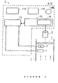
- the figure 1 schematically represents a ventilation installation, in this example of extraction of air from various premises by suction through a branched network of pipes.
- the branch 10 collects air a plurality of two columns 11, 12, each provided with a plurality of devices capable of clogging and inducing additional pressure drops, such as mouths 111, 112 and others, respectively 121, 122, and others, ventilation of premises such as kitchens or bathrooms in one or more apartment buildings.
- the branch 20 collects the air a plurality of three columns 21, 22, 23 each provided with a plurality of mouths 211, 212 and others, and 221, 222 and others, and 231, 232, 233, 239 and others, ventilation of premises of the same kind.
- CO 5 columns each comprising a particular number BO of mouths, indicated generally by the reference 120, with an associated air filter generally indicated by the reference 130.
- Each mouth 120 is equipped with one or more shutters so that the user of a room controls the opening, or the closure which isolates it partially from the installation, knowing that the so-called closing position allows a flow rate said to low water. It is therefore conceivable that, if all the suction ports 120 are almost closed, the fan 9 will generate a high vacuum throughout the installation, so have a good technical efficiency. However, in such a situation, the yield, ie the service rendered, is low.
- the mouths 120 are conventionally of two types possible: self-adjustable and hygro-adjustable, each type requiring a pressure difference greater than a particular minimum threshold of differential pressure PDs.
- a self-adjusting mouth extracts the air according to a compressed air flow at a nominal value Qn, that is to say that can only grow according to a very small slope as soon as the differential pressure applied to it exceeds the low minimum threshold of good functioning, that is to say the differential pressure PDs, while a hygro-adjustable mouth has a flow of air which increases with the humidity rate, the latter causing its gradual opening .
- cooking mouths which have higher flow rates than sanitary facilities and are generally associated with a 30-minute timer that the user orders to go through the air flow. maximum.
- a system is usually hygro or self-adjustable.
- the depression will therefore decrease in the installation since the various additional air flows that will then propagate in the columns and branches 10, 20 will see their flow be disturbed, and thus braked, by the friction on the walls of the corresponding conduit. This results in a pressure drop, which means that the fan 9 can not fully impose its depression value at the mouths 120.
- the effectiveness of a mouth 120 depends on the depression on its downstream side compared to the atmospheric pressure in the room, upstream side, it is understood that this depression must be sufficient to ensure the nominal air flow Qn, in practice a vacuum, or differential pressure PDs, at least 60 or 80 Pascal. It is understood that the level of clogging of the air filter 130 associated with the mouth 120 tends to raise the required values of differential pressure PDs.
- the mouth 239, at the upstream end, closed, of the column 23, is supposed to be the most disadvantaged mouth, that is to say the one whose path (23, 20) connecting it to the caisson 2 corresponds to a loss maximum load.
- This pressure drop which is due to that in the branch 20 and also in the column 23, given their section and their form of routing, also depends on the number of possible other open mouths 120, and their positions. It is easily understood that if all the mouths 231, 232 and others of the column 23 are open, the flow of air is then maximum, so that its flow is slowed by the maximum pressure drop.
- Each mouth 120 is equipped with the air filter 130 to avoid clogging the installation with greasy dusts, sticking to the walls. This is particularly the case when each mouth 120 is connected to the input of a dual flow heat exchanger box, as is explained below with reference to the figure 3 .
- the filter is particularly useful for blocking fat fumes from kitchens. So, so Generally, each column is connected to a mouth 120 through a filter 130, this filter 130 being integrated with the mouth 120 or integrated into the exchanger cabinet.
- the figure 2 represents the functional block diagram illustrating the constitution of the ventilation group 1.
- the ventilation unit 1 comprises a central unit 20C for controlling the motor 8 for driving the fan 9 intended to ensure the circulation of air in the mouths 120 which present a certain distribution along the column considered.
- the central unit 20C includes a time base 10B driving a calculation block 11C associated with sequencer circuits 12C managing the steps of the method according to the invention.
- the sequencer circuits 12C control servo circuits 13 controlling the circuits 14 for adjusting the power of the fan 9, through a control of the motor 8.
- the adjustment circuits 14 comprise circuits 16 for variable power supply of the motor 8.
- a flowmeter 5 and a pressure sensor 6 measure the two variables considered at the level of the fan 9, upstream at least with respect to the pressure sensor 6, to provide the measurements corresponding to the servocontrol circuits 13.
- the depression P above would be an overpressure in the case of an air blowing installation. In both cases, it is therefore an increase in the absolute difference of the current operating pressure with respect to the atmospheric pressure, of the two respective sides of the fan 9.
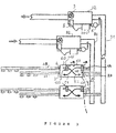
- the figure 3 schematically represents an installation comprising two twin architectures, namely a branched network installation of air intake from the apartments and a dual air blowing installation therein.
- This second installation has an architecture of the same type as the suction installation, the only difference being that the fan 9 considered provides an overpressure in the insufflation columns.
- each of these is equipped with a bidirectional internal heat exchanger box 60.
- the box 60 with static or rotary operation, with double flow is connected , by a column 81, insufflation, to a common outer blowing chamber 82, for example on the terrace, sucking air from the atmosphere.
- a column 91, extraction unit connects the box 60 to a common external air extraction box 92, referenced 2 on the figure 1 .
- the box 60 contains a double-flow heat exchanger 50 supplied with fresh air by the external column 81, for blowing air, through an inlet 1A, or external input link.
- the arrival 1A is connected to an outlet mouth 3, internal blowing, apartment side, continuing with a pipe or sheath 39 in the desired parts, the above link being made through a first circuit 51 of the exchanger 50.
- a sheath 49 for extracting stale air from one or more pieces results in an internal inlet mouth 4 of the cabinet 60, of internal extraction, which, through a second circuit 52 thermally coupled to the first circuit 51, joins a 2D start, that is to say an external output link, connected to the external column 91 exhaust air exhaust.
- the number of mouths 120 on the inner side can be increased as needed.
- References 11R and 41R denote a pair of air filter receiving locations 11F, 41F, for mounting two such filters in the input locations 11R and 41R, i.e. for each direction and each time upstream of the exchanger 50.
- the operation of the air suction installation will first be exposed with regard to the general appearance of a vacuum control curve P / air flow Q.
- the vacuum P would become an overpressure in the case air insufflation.
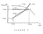
- the figure 4 illustrates the appearance of two conventional types of (de) pressure P relative to the air flow Q that can be imposed on the fan 9.
- a curve C30 which represents the natural vacuum response P / airflow Q of the fan 9, having a substantially horizontal first portion, precisely at a P depression with a slope which is only slightly negative, followed by a second part with slope becoming more and more negative for a rising airflow Q, that is to say that the fan 9 is in power limit.
- the setpoint curves which aim to avoid permanent operation at maximum power, are therefore located under the natural response curve C30.
- the first setpoint curve C10 is a so-called constant negative pressure regulation P, by imposing a maximum value of vacuum P, that is to say guaranteeing at least the sufficient level of differential pressure at each mouth 120, and this even if all these are open in the column 91 considered, so with a maximum pressure drop.
- the curve C11 is a variant curve, which indicates the drive power of the fan 9, which, it is increasing with the work to be provided, that is to say the evacuation of a growing mass of air per unit of time.
- the driving power above corresponds for example to the current or the voltage or power supply of the motor 8 or to a frequency of rotation Fr which is imposed on it, that is to say a parameter upstream of that or, it corresponds to a motor torque which it delivers at the output by a fan drive shaft 9. All the above parameters are therefore upstream parameters of the fan 9.
- the second setpoint curve C20 is an increasing vacuum regulation P with the air flow Q. Indeed, a very low airflow Q reflects the fact that some of the mouths 120 of the same column are closed, so that that the pressure drop in the columns does not exceed a certain limit. It is thus useless to try to compensate, by a high depression P, a loss of load which is non-existent beyond this limit, which can be estimated.
- the rise curve of the negative pressure P is relatively steep initially because it can not be excluded that an air flow Q, detected as being moderate, comes from a single column, with a loss of head high.
- the curve C20 therefore provides, with respect to the "horizontal" curve C10, an improvement in the energy efficiency of the installation, which is therefore limited to the zone of quasi-resting operation, and which, moreover, is not not totally optimal.
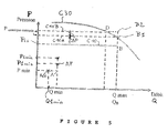
- the figure 5 represents a first example of regulation, with a so-called constant vacuum P, in which the vacuum P is maintained at a set point value Pcs over a range of air flows ranging from a minimum air flow rate Qmin to an air flow rate maximum Qmax, defining an upper limit point B of the above range.
- the point referenced A at the air flow rate Qmin, represents the minimum actual requirement for Pmin depression, that is to say that the setpoint curve is well above the usual need for low flow rates.
- Q air the minimum actual requirement for Pmin depression
- the set point of depression Pcs is to be increased by a quantity of value whose amplitude makes it possible to compensate for the additional pressure drop above. It will be understood that this amplitude increases over time, that is to say the progressive clogging of the filters 130, and only the cleaning or replacement of at least some of them allows to allow a return to, and possibly up to the initial setpoint. As shown in figure 5 , the rise of the setpoint curve causes it to reach the natural curve C30, that is to say that the point B, upper limit, comes into contact first (point B1 maximum end of a setpoint curve C10A replacing the curve C10) with the natural curve C30.
- the value can be added to any setpoint curve, such as the constant reference curve C10 to (de) pressure P or the setpoint curve C20 to (de) increasing pressure with the air flow Q.
- filter clogging statements 130 are initially carried out for a certain period of time, for example several months, preferably by noting the conditions of use, or environmental parameters, as for example. example, the rate of renewal of the air or an average rate of pollution of the air stale particles that will be trapped in the filter 41F of the internal inlet 4 per unit of time, corresponding to an hourly or daily rate or
- a time-stamping prediction table i.e., its growth as a function of time t, is used which is used in the present installation to define a loss value. charge as a function of the air flow Qm in the filter 41F considered. The value is then calculated by the formula:
- the reference Q BL denotes the largest air flow rate among all the maximum air flow rates of the mouths 120 of the respective housings.
- the measured pressure drop is corrected, ie normalized, so that it corresponds to the maximum individual air flow, since, after the measurement, this maximum individual air flow must be able to be ensured at all times. ulterior.
- the new set pressure Pcs is therefore: that is, the initial depression value P B of point B, increased by .
- the value thus calculated can constitute a shift constant, in rise, of the curve C10 at (de) constant pressure or the curve at increasing pressure C20.
- the new setpoint curve C20A which deviates from the previous setpoint curve C20, it can be expected that the correction is increasing with the air flow Q, that is to say it is of reduced amplitude when the air flow Q is low.
- the environment parameters are taken into account to modulate the clogging rate value, that is, if the apartment considered in this installation is estimated to present only a clogging time rate which does not represent that a fraction 1 / N of the "standard" rate in the table, the time t to take into account to read the table is to divide by this fraction, that is to say that it becomes tx N.
- the flow of time of the table is considered, during the reading, as having slowed down when the time rate of clogging of a particular apartment is lower than the standard rate.
- a direct measurement is carried out by equipping the filters 41 F with pressure sensors whose measurement makes it possible to determine a differential pressure value on the filter for a known air flow rate. Precisely, if the filter 41F gradually clogs, the individual air flow through it will decrease at determined differential pressure.
- the overall air flow rate of the column 91 will only be "slightly" reduced because of the clogging of the filter 41 F, since the local pressure drop in the cabinet 60 considered, and the increase thereof, represent only a small fraction of the total pressure drop in column 91. If, on the contrary, the overall air flow rate of the column 91 is then low, the increase in pressure drop in the cabinet 60 results in a more marked decrease in the air flow in the column in question 91, and thus also in the box 60.
- box 60 corresponds to a constant air flow and to a variation of depression remaining constant over for example 1 hour, one can note a sliding average of the evolution of the operating conditions over several weeks to translate this evolution into a control of drift of 'INCREASE one of the absolute value of the (de) pressure P of the fan 9.
- the measurement of the individual air flow at a filter 41 F can be performed by an air flow sensor associated therewith. However, it can also be expected to "close" temporarily all the boxes 60 except the one to be tested, so that the measurement of the overall air flow Q at the extraction box 92, provides a measuring the individual air flow rate of the filter 41F considered.
- the level of leakage of the installation will have previously been measured over the entire range of change of the set pressure Pcs to correct all the measurement of the overall air flow Q, in order to obtain the precise value of the individual air flow rate of the filter 41F, which, together with the differential pressure thereon, makes it possible to calculate a clogging rate.
- a third solution consists in making an indirect measurement of the clogging rate of all the filters.
- F The principle is to determine if the installation is still able to present the dynamics of airflows Q expected between the flow of Qmin minimum air and the maximum airflow Qmax, and this for respectively Pmin depression and Pcs depression.
- the air vents 120 are usually in the so-called closed state, allowing only low-flow airflow Q to pass, so that the installation operates at a perfectly known point, in the absence of clogging, which is the point A. If, however, the filters 41F have a start of clogging, the minimum depression Pmin is then insufficient to ensure the minimum air flow Qmin.
- a temporary stall from the setpoint curve, normally at constant pressure P B , to the vacuum value Pmin thus makes it possible to measure an air flow Q1min (point AQ of a current response curve Cx) less than the value Qmin measured during commissioning because of the pressure drop due to clogging.
- the negative drift Qlmin - Qmin of the variable whose value must be ensured, that is to say the airflow Q increases in absolute value over time t, with the growth of the clogging rate.
- the clogging rate decreases, because of the cleaning or replacement of filters 41F, the direction of the drift above is reversed, that is to say that the absolute value of the clogging level decreases.
- the servocontrol must command an adjustment at a depression Plmin of amplitude greater than Pmin, to compensate for the additional pressure drop. Due to clogging. It is thus a positive drift Plmin - Pmin of the amplitude of the control variable that constitutes the P-depression. In the absence of correction, the absolute value of depression P therefore tends to decrease, in this example to suction operation. Apart from the correction of increasing the amplitude of the depression P, a safety margin is furthermore maintained.
- Such a correction can be performed cyclically, from the initial value P B , by adding registration values as evoked on the figure 5 .
- first depression shift it is then necessary, for the subsequent readjustments, to shift the reference of depression, that is to say that Pmin is to be replaced by its update value Plmin, and Plmin is to be replaced by a value of depression P2min , representing the update of P1min.
- the setpoint depression can be compared with a maximum correction threshold value to generate an alarm if the threshold is exceeded, which means that the fan 9 is used to the limit of its possibilities for the maximum airflow. Qmax, and therefore this maximum airflow Qmax can no longer be guaranteed in the future. We must intervene to change the filters 41 F, or at least some of them.
- the figure 7 represents, very schematically, the instantaneous air flow Q as a function of time t, with a representation of the evolution of the daily air flow Q relative to two days distant from one or more months.
- the first day, of start of the installation presents ridges Qct of airflow Q, with a first peak QctM in the hour of midday and a second peak QctS1, here supposed of lower amplitude, the evening, with then dropped to the minimum level Qmin at night.
- the same kind of pattern for the subsequent day has generally the same shape but with Q airflow amplitudes which are less for QctM2 and QctS2 evening peaks.
- Each of these plots can be an average over several successive days.
- This "height" framing can, for example, consist in determining the minimum of a sum of airflow deviations Q of a sequence of homologous points (same hour), that is to say that one superimposes the two daily curves over the same period of a day.
- the decay curve Cdc can then pass through a pair of any homologous points, that is to say be at any height, since it is its slope that matters, this slope determining the direction of the drift of clogging, and the integral of this slope, that is to say the height shift of the two daily tracks, is representative of the clogging rate.
- the measured airflow value In order for the measurements to be less sensitive to the simultaneous opening uncertainties of all the outlets 120 supplying the peak values of the air flow rate, it is preferable to integrate the measured airflow value with several tens of minutes, for example one or two hours, in the meal periods. It is then the whole peak area of the airflow curve that provides the desired information, average peak airflow, which is then statistically exploited to determine if subsequent peaks deviate from notable way of the average reference value.
- the horizontal setpoint curve, at pressure Pcs is replaced by a so-called monotonous growth curve C20 according to the figure 6 , starting from the said minimum point A to reach the maximum point B.
- the set-point curve C20 has a very approximately parabolic shape with a horizontal axis, along the air flow axis Q, thus with a maximum slope of growth for the low air flows Q , this gradient decreasing progressively for the high air flows Q.
- This curve is a curve covering the possible needs in air flow Q, that is to say that the depression P is considered to be sufficient to ensure, in most of the possible open mouth distribution configurations 120, at least the nominal air flow Qn required in the cabinets 60, even those that are the most disadvantaged, that is to say located at the bottom of the columns 91.
- the curve C20 has a strong initial slope.
- the determination of the direction of the drift and the clogging rate of the filters 41F is effected as explained above.
- the depression supplement either of increasing value with the air flow Q, that is to say that the new setpoint curve C20A, located above the original setpoint curve C20, diverges with respect thereto.
- a high air flow Q means that a large number of mouths 120 are open and therefore it is necessary to overcome the clogging of a large number of filters 41F.
- the depression supplement can, for example, vary quadratically depending on the air flow Q.
- the operating parameters of the installation comprise, on the one hand, the instantaneous flow rate Q of the air collected by the fan 9, that is to say an "output” parameter, or downstream , fan 9 corresponding to the service rendered, and, secondly, parameters, "upstream”, fan operation control 9, that is to say, parameters related to the drive power applied to the fan 9 to provide the desired value of its downstream parameter, i.e. the desired P depression value on the servo setpoint curve.
- the initial set J0 of associated parameter values may only define one point of the setpoint curve C10, C20 on which it is located, but it will then be preferable for the comparison in step c) to be carried out at a given moment for which one of the values subsequent currents Vx is then of value substantially equal to the initial value of the parameter considered.
- the initial and current instants are preferably chosen at a time of day when the need for flow is stable.
- the initial and current instants can be chosen at night, since the flow requirement for the installation is then substantially constant from one day to the next. For example, by choosing the initial time and current during the night, the need for flow at these times may be equal to the minimum flow of the installation, because no occupant then requires a ventilation rate.
- the shape of the setpoint curve is known, however, it is possible, by extrapolation from the point defined by the initial set J0, to determine the position of a section of the setpoint curve as initially followed, ie say a response curve identical to the setpoint curve. The response curve, however, will drift as the filters clog.
- step c the drift to, in step d), estimate a drift level, that is, ie a clogging rate, according to a law increasing with measured drift.
- the curve of the law of variation is initially established by tests and stored in memory to use it as indicated, to transcode the power value of the motor 8, or other equivalent parameter, or the value of the engine torque, into a value of P. In other words, it is carried out the reading of a point of the curve C11 (driving power) and it is brought back into the system of coordinates P depression / air flow Q to be able to determine its distance to the associated setpoint curve C10, C20, that is to say, to measure the drift of the fan control 9.
- the figures 8 and 9 illustrate a model of the exhaust air extraction installation, for acquiring information on the state of the column 91 at each of the apartments, the problem being to locate the filters 41 F dirty, or at least to determine the overall fouling of filters 41 F of column 91.
- the column 91 can be modeled by a trunk of electrical resistors in series, resistor R1, point AA (connection of an upper stage), resistance R2, point AB (connection of an intermediate stage), resistance R3, point AC down (connection of a lower stage), each resistor R1, R2, R3 representing the pressure drop between two stages, in order starting from a roof terrace where the box 92 is located.
- each mouth 120 associated with a stage exchange filter 41F is equivalent to a resistance Ra, Rb, Rc branch derived at the respective point AA or AB or AC, whose free end, flat side, is grounded (atmosphere). This stage resistance Ra, Rb, Rc is variable (open or closed state of the mouth 120).
- the suction fan 9 at the top of the column 91 is represented by a negative bias supply voltage, the upper limit of which is at the mass (atmosphere) as the free ends of the mouths or branches "Ra", “Rb”, “Rc".
- References in quotation marks denote the element whose value is represented by the reference between these quotation marks, that is to say a mouth associated with a filter.
- a first type of stimulus may be the opening of a mouth "Rs”, which may be of calibrated type, at pressure drop Rs, at the bottom of the column 91, that is to say the so-called free end.
- the corresponding airflow will therefore directly disturb the entire column “R1”, “R2”, “R3”, and indirectly all the mouths “Ra”, “Rb”, “Rc”, as explained above.
- a large mouth of stimulus air Rs which will "unhook” some of the mouths “Ra”, “Rb”, “Rc”, that is, that is, to reduce the depression in at least the lower portion of the column 91 to less than 60 Pascal.
- the above stall means that the mouth 120 considered, which comprises a clamping tongue limiting the individual air flow, in throttling the air passage under consideration, above the nominal low air flow threshold Qn, no longer operates at almost constant air flow regardless of the (de) pressure P, but then operates with a individual airflow which varies in the same direction as the amplitude of the depression P.
- the response curve sections for these two respective modes of operation are therefore connected by an elbow zone, as shown in FIG. figure 10 , explained later.
- the stimulus above makes it possible to detect that the mouth 120 considered operates on one or the other of these two sections. Indeed, if the amplitude of the depression P is initially only slightly reduced, that is to say with a weak stimulus, all the mouths 120 remain in proper operation, that is to say that the flow air Q in column 91 remains almost unchanged, except for the reduction of leaks, which is initially easy to determine for the functional range of depression P. On the other hand, if the amplitude of the vacuum P is sufficiently reduced so that at least a mouth 120 picks up, that is to say no longer has a sufficient differential pressure, given the clogging, to ensure the nominal air flow Qn causing the clamping, the air flow Q in the column 91 will then decrease in an accelerated manner since one no longer operates at constant airflow Q.
- the above stall can then be linked to a clogging of the associated filter 41 F, that is to say that the instantaneous differential pressure is perhaps greater than the low threshold nominal value PDs desired for a filter 41 F to the new state, but this differential pressure value PDs is now insufficient to ensure the desired individual air flow rate Qn, actuation of the clamping tongue, through the filter 41 F having a certain level of clogging.
- the calculation block 11C knows the responses of the various types of mouth 120 in such a case, and therefore in particular the position of the elbow, it can, according to the observed variation of the air flow Q in the column 91 and the P depression, determine the number of open mouths 120 and their positions since the stall response signature of each mouth 130 is perceived through an instantaneous pressure loss that is specific to each.
- the calculation block 11C determines, at the output level (box 92) of the column 91, the composite response curve of the various ports 120, and this response curve is a signature of the open state or closed mouths 120 and their type.
- This composite response curve thus has a succession of elbows each corresponding to a stall of a mouth 120. If all the filters 41F have the same level of clogging, it is therefore the mouths 120 the most disadvantaged who will pick up the first and other will follow, in the manner of dominoes erect and cascading, thus presenting the succession of bends above.
- the low point AC of the column 91 (point of connection of the mouth "Rc", the most disadvantaged) is at a certain potential, sufficiently negative, that is to say say at least a fall from 60 to 80 Pascal.
- the rest of the voltage drop, to go down to the supply voltage -Va, is distributed over the resistors R3, R2, R1, this distribution depending on the state of the various outlets 120.
- the figure 9 represents, on the abscissa, the voltage (representing the amplitude of the depression P) at the various stages, on the ordinate.
- the horizontal arrow FC of tension or depression P, thus becomes an arrow FCA of almost zero length, and the arrows FB and FA become respective arrows FBA and FAA which are shortened.
- the service mouth "Rs” is calibrated to a standard air flow Qe, not necessarily greater than the nominal air flow of the various mouths 120.
- the corresponding stimulus will be of limited amplitude and the lower mouth “Rc” will not be totally shunted, whereas it was the case for a mouth “Rs” of large size and not restrained.
- the response curve is then intermediate between the curves C8 and C8A. The interest of such a case is that one knows exactly the amplitude of the stimulus.
- the above measurements are tainted by noise because they relate possibly to small variations, and are further disturbed by the activity of the mouths 120 of the other columns. It is therefore preferable to use the principle of the sampling oscilloscope, that is to say to repeat cyclically a modulation of opening / closing of "Rs" to smooth the results observed.
- each of the individual heat exchangers 60 is successively looped back on itself, at the level of the internal, outlet 3 and inlet 4 mouths, in order to keep only a local loop of the box 60, comprising the two filters 11F, 41F of the exchanger box 60 of the apartment. Then, if we shun these filters 11F, 41 F by a local bypass circuit, we can determine the pressure drop they induced. In a dual manner, it is possible to temporarily cut off this local loop, that is to say isolate the box 60 and measure the response, that is to say the modification of the state of the column 91. Then, it is necessary to preferably, corresponding control means, distributed in the stages.
- This state switching is preferably performed at night, that is to say when the frequency or probability of switching the mouths 120 is low, which reduces the risk of measurement noise.
- the calculation block 11C preferably performs a progressive commutation of the air flow by progressive switching of the state of the standard service mouth "Rs" between extreme states, opening and closing, and is carried out, in a plurality N of current instants Tx, Ty, Tz, a plurality N of samplings of the response of the installation in terms of said current values Vx, Vy, Vz of said Y parameters according to step b) and, according to the plurality of so-called drift levels thus obtained, a response sensitivity curve of the installation is established with respect to said air flow switching.
- the modulation of the air flow Q thus obtained by controlling the service port "Rs" can be performed with operation at (de) pressure P constant, which avoids interference between variables.
- it can be planned to operate according to a predetermined regulation curve with (de) pressure of increasing amplitude with the air flow Q, since, knowing this curve, it will be possible to separate the two variations of the two variables P and Q.
- the stimulus can be a variation of the depression P, that is to say a modulation of the bias voltage-Va.
- the figure 10 thus shows a curve C40 of depression P / airflow Q of the installation, in which, the state of opening of the various mouths 120 being supposed to be fixed, the value of the depression P is varied starting from, for example, the maximum value P B.
- the curve C40 has a first section, of upper end, C41 for which the slope is maximal, since all the mouths 120 then operate with clamping, that is to say that their individual air flow is almost insensitive to the value of the differential pressure on the mouth 120 considered.
- the curve composite of air flow Q in the column 91 thus has, on a second section following C42, a lower slope than that of the first section C41, this slope reduction reflecting the influence, in the overall air flow Q of the column 91, the individual flow of the mouth 120 having off the hook.
- the individual air flow passing through a mouth 120 sensitive to the local differential pressure on the mouth 120 considered and less than the nominal air flow clamping Qn, undergoes a pressure drop depending on the position of the mouth 120 in column 91 and as a function of the air flow of the other mouths 120.
- the second section C42 has an overall slope which depends on the response curve of the type of mouth 130 considered but which also depends on the loss of charge caused by the constant air flow of the other mouths 120.
- the stimulus is for example produced by the shift of the value of an operating control parameter of the fan 9, constituting the said associated parameter (de) pressure P, electric power W, output torque, rotation frequency Fr.
- the shift will modify the operating point of the mouths 120 on for example a portion of airflow response curve regulated by a throttling tongue, that is to say, will make it slightly increase or decrease, or even greatly decrease if the differential depression perceived by the mouth 120 falls below the nominal threshold differential pressure threshold PDs.
- the said drift measurement corresponds to a measurement of an amplitude of the said sensitivity, represented by an amplitude of the said induced variation of the associated parameter P, W, torque, Fr.
- the calculation block 11C makes a modification to an adjustment value of a fan operation control parameter, constituting the said associated parameter W, torque, Fr , so as to compensate, at least according to a certain percentage, for said variation of said associated parameter W, torque, Fr induced by said offset Qx air flow, and the said sensitivity of the said associated parameter W, torque, Fr is determined from the value of the said modification, referred to the said percentage.
Abstract
Description
La présente invention concerne la régulation du débit d'air dans les installations de ventilation comportant des colonnes d'extraction ou d'insufflation d'air desservant chacune plusieurs locaux.The present invention relates to the regulation of air flow in ventilation installations comprising extraction columns or air insufflation each serving several premises.
Une telle installation comporte un groupe de mise en circulation d'air au moyen d'un moto-ventilateur logé dans un caisson usuellement disposé en terrasse d'un immeuble dont les appartements sont desservis par des colonnes d'arrivée et/ou d'aspiration d'air. Pour limiter les pertes thermiques, chaque appartement peut être équipé d'un coffret à double flux, c'est-à-dire à flux croisés entre l'air neuf entrant et l'air vicié qui est évacué dans la colonne d'aspiration.Such an installation comprises a circulating unit of air by means of a motor-fan housed in a box usually placed on the terrace of a building whose apartments are served by columns of arrival and / or suction air. To limit heat losses, each apartment can be equipped with a dual flow cabinet, that is to say, with cross flows between incoming fresh air and stale air that is discharged into the suction column.
Le moto-ventilateur comporte un filtre en amont et, de même, chaque coffret d'appartement comporte une paire de filtres amont, c'est-à-dire un filtre d'entrée d'appartement, en sortie locale de la colonne d'arrivée, et un filtre de sortie d'appartement, au raccordement entre une gaine d'extraction d'air de l'appartement et le coffret.The motor-fan comprises an upstream filter and, likewise, each apartment cabinet comprises a pair of upstream filters, that is to say an apartment input filter, at the local output of the column of arrival, and an apartment exit filter, at the connection between an exhaust duct of the apartment and the cabinet.
Au fil du temps, le colmatage des filtres augmente la perte de charge dans l'installation, donc l'efficacité du ventilateur. Au-delà d'un certain niveau, il ne peut plus assurer la qualité de service voulue.Over time, the clogging of the filters increases the pressure drop in the installation, therefore the efficiency of the fan. Beyond a certain level, it can no longer ensure the desired quality of service.
Comme les filtres des coffrets individuels sont donc répartis dans les divers appartements, il est évidemment exclu, pour des questions de coût de personnel, que des membres du service d'entretien passent cycliquement pour vérifier l'état de colmatage des filtres et, le cas échéant, procéder à leur remplacement.As the filters of the individual boxes are thus distributed in the various apartments, it is obviously excluded, for questions of personnel cost, that members of the maintenance service pass cyclically to check the clogging condition of the filters and, if appropriate, replace them.
Par ailleurs,
La présente invention vise à proposer une solution au problème susmentionné de surveillance de l'état d'encrassement, ou colmatage, des filtres d'entrée et/ou de sortie d'air de locaux respectifs.The present invention aims at providing a solution to the above-mentioned problem of monitoring the state of fouling, or clogging, of the inlet and / or outlet air filters of respective premises.
A cet effet, l'invention concerne tout d'abord un procédé d'estimation de l'évolution d'un niveau de colmatage de filtres à air installés dans divers locaux et reliés à une installation d'au moins une conduite d'échange d'air, activée par un ventilateur entraîné par un moteur, caractérisé par la suite des étapes suivantes :
- a) à un instant initial, on détermine et mémorise un jeu initial J0 de valeurs de paramètres associés de fonctionnement de l'installation, paramètres comprenant un paramètre de débit d'air instantané assuré par le ventilateur et au moins un paramètre instantané associé de fonctionnement du ventilateur pour assurer le débit d'air instantané considéré, les paramètres associés variant de façon corrélée pour définir une courbe de réponse, initiale, prévue pour l'installation,
- b) à un instant courant, on détermine des valeurs courantes des dits paramètres pour un point de fonctionnement courant sur une dite courbe de réponse, actuelle,
- c) on compare les valeurs courantes au jeu initial J0 pour déterminer une direction de dérive du point de fonctionnement courant par rapport à la courbe de réponse initiale, et
- d) on détermine un sens d'évolution du niveau de colmatage d'après la direction de la dérive.
- a) at an initial time, an initial set J0 of associated parameter values of the operation of the installation are determined and stored, parameters comprising an instantaneous air flow parameter provided by the fan and at least one associated instantaneous parameter of operation of the fan to provide the instantaneous air flow rate considered, the associated parameters varying in correlation to define an initial response curve expected for the installation,
- b) at a current time, current values of said parameters are determined for a current operating point on a said current response curve,
- c) comparing the current values with the initial clearance J0 to determine a drift direction of the current operating point with respect to the initial response curve, and
- d) a direction of evolution of the clogging level is determined according to the direction of the drift.
On notera tout d'abord que l'instant initial est arbitraire. De préférence, ce sera le moment de la mise en service de l'installation. Toutefois, de façon générale, on peut prévoir un instant initial "glissant", pour suivre l'état de l'installation au fil des remplacements ou nettoyages de certains filtres. L'invention permet ainsi de suivre, au fil du temps, les ondulations de colmatage global de l'installation, c'est-à-dire, d'une part, le colmatage progressif de tous les filtres, chaque filtre ayant une vitesse propre d'évolution de son colmatage, en fonction de la pollution de l'air qui le traverse et de la durée d'ouverture de la bouche correspondante, et, d'autre part, la chute brutale de colmatage des bouches ou coffrets dont l'utilisateur a nettoyé ou remplacé le filtre.It will be noted first of all that the initial moment is arbitrary. Preferably, this will be the time of commissioning the installation. However, in general, we can provide an initial moment "sliding" to monitor the status of the installation over the replacement or cleaning of some filters. The invention thus makes it possible, over time, to follow the overall clogging corrugations of the installation, that is to say, on the one hand, the progressive clogging of all the filters, each filter having its own speed. evolution of its clogging, depending on the pollution of the air passing through and the opening time of the corresponding mouth, and on the other hand, the sudden drop in clogging of the mouths or boxes of which user has cleaned or replaced the filter.
De préférence, les instants initial et courant sont choisis à une période de la journée où le besoin en débit est stable. En particulier, les instants initial et courant peuvent être choisis la nuit, car le besoin en débit pour l'installation est alors sensiblement constant d'une journée à l'autre. Par exemple, en choisissant l'instant initial et courant durant la nuit, le besoin en débit à ces instants peut être égal au débit minimal de l'installation, car aucun occupant ne demande alors un débit de ventilation.Preferably, the initial and current times are chosen at a time of the day when the need for flow is stable. In particular, the initial and current instants can be chosen at night, since the flow requirement for the installation is then substantially constant from one day to the next. For example, by choosing the initial time and current during the night, the need for flow at these times may be equal to the minimum flow of the installation, because no occupant then requires a ventilation rate.
On notera aussi que, comme le colmatage induit une perte de charge, l'invention peut s'appliquer à tout réseau de fluide, c'est-à-dire de gaz ou de liquide.It will also be noted that, since the clogging induces a pressure drop, the invention can be applied to any fluid network, that is to say gas or liquid.
Par ailleurs, les paramètres de fonctionnement permettant d'assurer le débit considéré sont avantageusement choisis parmi : la (dé)pression que doit assurer le ventilateur, la puissance électrique du moteur d'entraînement du ventilateur, le couple de sortie de l'arbre moteur, l'intensité du courant consommé par le moteur ou la fréquence de rotation imposée au moteur.Moreover, the operating parameters making it possible to ensure the flow rate considered are advantageously chosen from: the (de) pressure that the fan must provide, the electrical power of the fan drive motor, the output torque of the motor shaft , the intensity of the current consumed by the engine or the frequency of rotation imposed on the engine.
De préférence, à l'étape c), on mesure la dérive pour, à l'étape d), estimer un niveau de dérive de colmatage, selon une loi croissant avec la dérive mesurée.Preferably, in step c), the drift is measured for, in step d), to estimate a level of clogging drift, according to a law increasing with the drift measured.
On peut ainsi disposer d'une valeur globale de colmatage de l'installation, pour décider d'effectuer une action de réglage de consigne de fonctionnement ou un remplacement des filtres si un seuil haut de colmatage est franchi.It is thus possible to have a global value of clogging of the installation, to decide to carry out an operation setpoint adjustment action or a replacement of the filters if a high clogging threshold is crossed.
Selon un mode particulier de mise en oeuvre du procédé, on mémorise de dits niveaux de dérive de colmatage au fil du temps pour ainsi établir une table de prédiction temporelle de l'évolution du niveau de colmatage, et, par la suite, on utilise la table de prédiction pour effectuer la dite estimation du niveau de dérive de colmatage.According to a particular mode of implementation of the method, said levels of clogging drift are memorized over time, thereby establishing a temporal prediction table of the evolution of the clogging level, and, subsequently, using the prediction table for making said estimate of the level of clogging drift.
La table peut être établie sur une première période de fonctionnement de l'installation, pour ensuite extrapoler la courbe d'évolution du colmatage ainsi établie, ou bien la table peut être établie à partir d'une autre installation du même type, plus ancienne, pour ainsi disposer de la dite courbe sur une longue période, donc sans nécessité d'extrapolation.The table can be established on a first period of operation of the installation, then extrapolate the evolution curve of the clogging thus established, or the table can be established from another installation of the same type, older, so to have the said curve over a long period, so without the need for extrapolation.
Pour affiner l'exploitation de la table, on compare des conditions actuelles d'environnement effectif d'utilisation des filtres à des conditions homologues ayant existé lors de l'établissement de la table de prédiction, et on dilate, respectivement condense, une échelle de temps de la table de prédiction selon que les conditions actuelles d'environnement effectif sont moins dures, respectivement plus dures, que celles associées à la table de prédiction.To refine the exploitation of the table, one compares current conditions of effective environment of use of the filters with homologous conditions having existed at the time of the establishment of the prediction table, and one dilates, respectively condenses, a scale of time of the prediction table according to whether the actual environment conditions are less hard, respectively harder, than those associated with the prediction table.
Les informations sur le colmatage peuvent servir à déterminer une valeur de périodicité d'interventions à prévoir pour le remplacement des filtres.The clogging information can be used to determine a periodicity value of interventions to be expected for filter replacement.
Toutefois, en outre, il est avantageux d'utiliser les informations de colmatage pour ajuster les conditions de fonctionnement de l'installation, c'est-à-dire maintenir les performances requises. En effet, en l'absence d'ajustements, il faudrait prendre une grande marge de sécurité pour tolérer le colmatage, cette marge de sécurité représentant un excédent de consommation électrique, qui n'aurait sa raison d'être qu'en fin de cycle, c'est-à-dire lorsque le niveau de colmatage des filtres a atteint la limite admissible. La détermination des informations relatives au colmatage constitue ainsi une première phase, d'estimation de l'état de colmatage de l'installation, pour que, dans une seconde phase, celle-ci détermine elle-même de nouvelles conditions de fonctionnement, parfaitement adaptées aux nouvelles conditions de colmatage. L'installation étant ainsi auto-adaptative, il est donc inutile de prévoir une grande marge de sécurité en ce qui concerne la (dé)pression que doit assurer le ventilateur, c'est-à-dire la puissance de celui-ci.However, in addition, it is advantageous to use the clogging information to adjust the operating conditions of the installation, that is to say maintain the required performance. Indeed, in the absence of adjustments, it would be necessary to take a a large margin of safety to tolerate clogging, this margin of safety representing a surplus of electricity consumption, which would have its reason to be at the end of the cycle, that is to say when the clogging level of the filters has reached the allowable limit. The determination of the information relating to the clogging thus constitutes a first phase, of estimating the state of clogging of the installation, so that, in a second phase, the latter itself determines new operating conditions that are perfectly adapted. new sealing conditions. The installation is thus self-adaptive, it is therefore unnecessary to provide a large margin of safety with respect to the (de) pressure that must ensure the fan, that is to say, the power of it.
Ainsi, on peut prévoir de corriger une courbe de consigne de régulation du ventilateur en lui appliquant une dérive de consigne dans un sens fonction de la dite direction de dérive du colmatage.Thus, provision may be made to correct a control curve of the fan by applying a setpoint drift in a direction according to said drift direction clogging.
En particulier, en pareil cas, on peut affecter, à la dérive de consigne, une amplitude fonction du dit niveau de dérive de colmatage.In particular, in such a case, it is possible to assign, on the set drift, an amplitude that is a function of the said level of clogging drift.
Dans une forme particulière de régulation, la courbe de consigne spécifiant une pression de consigne déterminée pour tout débit d'air, l'amplitude de la dérive de consigne, de pression, est de la forme :
![]()
![]()
QBL est une valeur de débit d'air individuel maximal prévu pour une bouche de la conduite, c'est-à-dire uen bouche à débit d'air maximal par rapport aux autres.In a particular form of regulation, the setpoint curve specifying a determined setpoint pressure for any airflow, the amplitude of the setpoint drift, of pressure, is of the form: ![]()
![]()
Q BL is a maximum individual air flow value expected for a pipe mouth, ie a maximum air flow mouth with respect to the others.
Dans une autre forme particulière de régulation, la courbe de consigne spécifiant un débit d'air de consigne, l'amplitude de la dérive de consigne, de pression, est de la forme :
![]()
Plmin est une valeur courante de pression pour assurer le débit d'air de consigne,
Pmin est une valeur initiale de pression pour assurer le débit d'air de consigne,
QB est, comme ci-dessus, une valeur de débit d'air individuel maximal prévu pour une bouche de la conduite, et
Qmin est une valeur de débit d'air Q minimal prévu pour l'installation.In another particular form of regulation, the setpoint curve specifying a set air flow, the amplitude of the setpoint drift, of pressure, is of the form: ![]()
Plmin is a current value of pressure to ensure the set air flow,
Pmin is an initial value of pressure to ensure the set air flow,
Q B is, as above, a maximum individual air flow value expected for a pipe mouth, and
Qmin is a minimum Q airflow value expected for installation.
Dans les deux cas ci-dessus, on peut corriger la courbe de consigne en y ajoutant une fonction de la valeur de l'amplitude ![]()
![]()
La valeur de la dérive de pression ![]()
![]()
Pour signaler une dérive excessive, nécessitant une intervention sur les filtres, on compare le niveau de dérive à un seuil haut, de dérive admissible, et on engendre une alarme si le seuil haut est atteint.To signal an excessive drift, requiring intervention on the filters, the drift level is compared to a high threshold, permissible drift, and an alarm is generated if the high threshold is reached.
Dans un mode de mise en oeuvre du procédé,
- à l'étape b), on applique un stimulus sous forme d'un décalage de pression d'une valeur courante de pression d'air assurée par le ventilateur, par décalage de la valeur d'un dit paramètre associé, par rapport à une valeur homologue du jeu initial J0, et,
- à l'étape c), à titre de dite dérive, on mesure une variation de débit d'air, induite par le dit décalage de pression.
- in step b), a stimulus is applied in the form of a pressure offset of a current value of air pressure supplied by the fan, by shifting the value of a said associated parameter, relative to a homologous value of the initial set J0, and,
- in step c), as said drift, a change in air flow is measured, induced by said pressure offset.
En pareil cas, on peut prévoir que :
- on répète, au moins une fois, à un instant courant ultérieur, les étapes ci-dessus, en calculant à chaque fois une pente courante respective et
 de variation de débit d'air par rapport à une variation de pression, et,
- à l'étape c), on compare les pentes courantes respectives
 pour déterminer la dite direction de dérive du point de fonctionnement courant.
- repeating, at least once, at a subsequent current time, the steps above, each time calculating a respective current slope andof variation of air flow with respect to a variation of pressure, and,
- in step c), the respective current slopes are compared to determine said drift direction of the current operating point.
Ainsi, à mesure que croît le colmatage, la perte de charge correspondante dans les filtres limite l'accroissement du débit d'air en cas de stimulus d'accroissement de (dé)pression. En d'autres termes, l'installation présente une signature, de réponse aux stimuli d'augmentation de (dé)pression, qui s'affaiblit, puisque le débit d'air est bridé par le colmatage.Thus, as the clogging increases, the corresponding pressure drop in the filters limits the increase in the air flow rate in the event of a (de) pressure increase stimulus. In other words, the installation has a signature, response to stimuli increase (de) pressure, which weakens, since the air flow is clamped by clogging.
Pour simplifier les calculs, la variation de pression est normée à une même valeur prédéterminée ![]()
![]()
Dans ces derniers modes de mise en oeuvre, il peut être prévu que le stimulus soit produit par le décalage de la valeur d'un paramètre de commande de fonctionnement du ventilateur, constituant le dit paramètre associé, par exemple la puissance électrique du moteur d'entraînement du ventilateur ou encore la fréquence de rotation qui lui est imposée.In these latter modes of implementation, it can be provided that the stimulus is produced by the shift of the value of a fan operation control parameter, constituting the said associated parameter, for example the electric power of the motor. fan drive or the frequency of rotation imposed on it.
Dans un autre mode de mise en oeuvre du procédé :
- on applique un stimulus sous forme d'un décalage d'une valeur courante du dit débit d'air Qx du ventilateur, par rapport à une valeur homologue Q0 du jeu initial J0,

- on détecte une variation d'un dit paramètre associé induite par le dit décalage de débit d'air, et
- on détermine le dit sens d'évolution du niveau de colmatage d'après un signe d'une sensibilité du paramètre associé vis-à-vis du dit stimulus.
- we apply a stimulus in the form of an offset a current value of said fan air flow Qx, relative to a homologous value Q0 of the initial clearance J0,
- a variation of a said associated parameter induced by the said air flow offset is detected, and
- the said direction of evolution of the clogging level is determined according to a sign of a sensitivity of the associated parameter with respect to the said stimulus.
La dite mesure de dérive correspond par exemple à une mesure d'une amplitude de la dite sensibilité, représentée par une amplitude de la dite variation induite du paramètre associé.The said drift measurement corresponds for example to a measurement of an amplitude of the said sensitivity, represented by an amplitude of the said induced variation of the associated parameter.
Le stimulus peut être naturel, c'est-à-dire correspondre à l'ouverture ou la fermeture d'une bouche par un utilisateur. Il peut aussi être provoqué par un gestionnaire de l'installation, c'est-à-dire une personne ou bien un système électronique pilotant le ventilateur.The stimulus can be natural, that is to say, correspond to the opening or closing of a mouth by a user. It can also be caused by a manager of the installation, that is to say a person or an electronic system controlling the fan.
La variation de débit d'air se traduit donc par une variation des conditions de charge du ventilateur.The variation of air flow therefore results in a variation of the fan load conditions.
D'une part, si le niveau d'alimentation électrique de celui-ci est fixe, c'est-à-dire si le ventilateur fonctionne selon une courbe de réponse pression/débit d'air naturelle, une augmentation du débit d'air va donc diminuer la dépression produite par le ventilateur, si l'on suppose qu'il fonctionne en aspiration.On the one hand, if the power supply level of the latter is fixed, ie if the fan operates according to a natural air pressure / flow rate response curve, an increase in the air flow rate will therefore reduce the depression produced by the fan, if it is assumed that it operates in suction.
D'autre part, si la puissance d'alimentation du ventilateur est asservie par un dispositif électronique pour rester sur une courbe de réponse de consigne, la variation de pression, provoquée par le stimulus de variation de débit d'air, va être compensée par l'asservissement, c'est-à-dire masquée, et c'est donc la nouvelle commande d'asservissement appliquée au ventilateur qui va constituer la signature de réponse de l'installation au stimulus.On the other hand, if the power supply of the fan is controlled by an electronic device to remain on a setpoint response curve, the pressure variation, caused by the air flow variation stimulus, will be compensated by enslavement, that is to say hidden, and so the new order enslavement applied to the fan that will be the response signature of the installation to the stimulus.
En bref, le stimulus créé au niveau du paramètre de service, "aval", de l'installation, c'est-à-dire le service de débit d'air suffisant à assurer pour les utilisateurs, induit une modification d'au moins un paramètre "amont", permettant d'assurer la valeur voulue du paramètre aval, de débit d'air, ce paramètre amont modifié pouvant être, selon les deux cas exposés ci-dessus, la (dé)pression produite par le ventilateur ou bien la puissance d'entraînement de celui-ci.In short, the stimulus created at the "downstream" service parameter of the installation, ie the sufficient airflow service to be provided to the users, induces a modification of at least an "upstream" parameter, making it possible to ensure the desired value of the downstream parameter, of the air flow, this modified upstream parameter being able, in the two cases described above, to be the (de) pressure produced by the fan or else the driving power of it.
En pareil cas, on peut prévoir que :
- on répète au moins une fois les étapes ci-dessus, à un instant courant ultérieur, et
- on calcule à chaque fois une pente courante respective dont le signe de l'évolution de la valeur au fil du temps indique le sens d'évolution du niveau de colmatage.

Comme évoqué ci-dessus, en ce qui concerne le cas d'un ventilateur à puissance asservie, dans une étape finale, pour déterminer la dite sensibilité du paramètre associé, on peut apporter une modification à une valeur de réglage d'un paramètre de commande de fonctionnement du ventilateur, constituant le dit paramètre associé, de façon à compenser, au moins selon un certain pourcentage, la dite variation du dit paramètre associé induite par le dit décalage de débit d'air, et la dite sensibilité du dit paramètre associé est déterminée d'après la valeur de la dite modification apportée, rapportée au dit pourcentage.
- the above steps are repeated at least once, at a later point in time, and
- a respective current slope is calculated each time whose sign of the evolution of the value over time indicates the direction of evolution of the level of clogging.
As mentioned above, as regards the case of a fan with controlled power, in a final step, to determine the said sensitivity of the associated parameter, it is possible to make a modification to a control parameter of a control parameter of operation of the fan, constituting said associated parameter, so as to compensate, at least according to a certain percentage, said variation of said associated parameter induced by said air flow offset, and said sensitivity of said associated parameter is determined according to the value of the said modification, referred to the said percentage.
Dans un mode de mise en oeuvre particulier du procédé, ayant prévu une bouche de service étalon, à débit étalon, on commute son état pour passer, dans un sens quelconque connu, entre deux états extrêmes, respectivement de fermeture et d'ouverture, afin d'engendrer, à l'instant courant Tx, un décalage ![]()
- et on effectue les étapes b) et suivantes.
- and performing steps b) and following.
Si, par exemple, on ouvre la bouche étalon, elle va donc partiellement court-circuiter les autres bouches d'une colonne constituant une dite conduite, avec un effet de court-circuit d'autant plus marqué que celles-ci en sont proches et sont colmatées. Ainsi, et de façon très schématique, si le filtre d'une bouche proche est propre, la perte de charge sur celui-ci est limitée, et il en est donc de même pour la chute, ainsi provoquée, de la pression différentielle.If, for example, the standard mouth is opened, it will thus partially short-circuit the other mouths of a column constituting a said conduct, with a short-circuit effect all the more marked that they are close and are clogged. Thus, and very schematically, if the filter of a close mouth is clean, the loss of load on it is limited, and it is the same for the fall, thus caused, of the differential pressure.
Si l'on suppose, à titre purement didactique, qu'il n'y a qu'une bouche d'appartement d'ouverte dans l'installation, l'ouverture de la bouche étalon va doubler le débit d'air entrant dans la conduite commune de raccordement, en supposant, pour la simplicité de l'explication, que les deux bouches sont à même débit nominal. Par contre, si le filtre de la bouche d'appartement est colmaté, sa pression différentielle est élevée, c'est-à-dire que la colonne de raccordement "manque" d'air à ce niveau. L'ouverture de la bouche étalon va donc modifier plus profondément le niveau de pression dans la colonne, c'est-à-dire plus que doubler l'arrivée d'air et donc fortement ramener la pression interne vers la pression atmosphérique, puisque la bouche étalon va assurer un débit d'air bien supérieur à celui traversant le filtre colmaté.If one assumes, purely for didactic purposes, that there is only one open-air opening in the installation, the opening of the standard mouth will double the flow of air entering the room. common connection pipe, assuming, for the sake of simplicity of explanation, that the two mouths are at the same nominal flow. On the other hand, if the filter of the apartment mouth is clogged, its differential pressure is high, that is to say that the connecting column "lacks" air at this level. The opening of the standard mouth will therefore modify the pressure level in the column more deeply, that is to say more than double the air inlet and thus strongly reduce the internal pressure towards the atmospheric pressure, since the standard mouth will ensure an air flow much higher than that through the clogged filter.
En pareil cas, de façon avantageuse, on effectue une commutation progressive de débit d'air par commutation progressive de l'état de la bouche de service étalon entre les états extrêmes et on effectue, en une pluralité N d'instants courants, une dite pluralité N d'échantillonnages de la réponse de l'installation en termes de dites valeurs courantes des dits paramètres selon l'étape b) et, d'après la pluralité de dits niveaux de dérive ainsi obtenus, on établit une courbe de sensibilité de réponse de l'installation vis-à-vis de la dite commutation de débit d'air.In such a case, advantageously, a progressive commutation of the air flow is carried out by progressive switching of the state of the standard service mouth between the extreme states and, in a plurality N of current instants, a so-called plurality N of samplings of the response of the installation in terms of said current values of said parameters according to step b) and, according to the plurality of said drift levels thus obtained, a response sensitivity curve is established of the installation vis-à-vis the said air flow switch.
On peut alors prévoir que :
- on modélise l'état d'une autre pluralité de filtres de la dite conduite, par une équation comportant, en variables, les niveaux respectifs de colmatage de l'autre pluralité de filtres,
- on effectue une dite pluralité d'échantillonnages au moins égale à l'autre pluralité de filtres, et
- on établit ainsi au moins une dite autre pluralité de dites équations, ce qui permet d'en déterminer une dite autre pluralité de valeurs des variables de colmatage.
- the state of another plurality of filters of said pipe is modeled by an equation comprising, in variables, the respective levels of clogging of the other plurality of filters,
- one of said plurality of samplings is performed at least equal to the other plurality of filters, and
- at least one of said other plurality of said equations is thus established, which makes it possible to determine one of said other plurality of values of the clogging variables.
Ainsi, la commutation progressive de la bouche étalon équivaut à injecter N valeurs de stimuli pour ainsi déterminer autant de signatures de réponse de l'installation. L'analyse de la corrélation entre ces signatures, c'est-à-dire la corrélation due au fait que le niveau déterminé de colmatage de chaque filtre se manifeste dans chaque équation, permet donc d'individualiser le niveau de colmatage de chaque filtre. Il s'agit là d'un résultat de grande valeur puisqu'il permet d'établir un diagnostic à distance pour chaque filtre, donc sans devoir effectuer de visites périodiques sur place.Thus, the progressive switching of the standard mouth is equivalent to injecting N stimulus values to thus determine as many response signatures of the installation. The analysis of the correlation between these signatures, that is to say the correlation due to the fact that the determined level of clogging of each filter is manifested in each equation, thus makes it possible to individualize the level of clogging of each filter. This is a result of great value since it allows to establish a remote diagnosis for each filter, so without having to make periodic visits on site.
En particulier, comme les filtres de chaque local respectif sont reliés de façon étagée sur la conduite, ils ne sont pas perçus comme étant strictement mutuellement en parallèle, puisqu'un tronçon de conduite les sépare. De la sorte, la réponse de chaque filtre se manifeste, au niveau du ventilateur, à travers une perte de charge instantanée dans la conduite, la valeur de cette perte de charge instantanée étant spécifique à chaque filtre. En d'autres termes, chaque filtre est associé à deux variables qui sont son niveau de colmatage (et donc sa perte de charge à un débit d'air instantané) et la perte de charge que subit ce débit d'air jusqu'au ventilateur. Ainsi, bien que les bouches, équipées de filtres, s'influencent mutuellement de par le flux d'air que chacune échange avec la conduite, et qui crée un supplément de perte de charge, la bouche à l'origine d'une modification de l'état (dé)pression / débit d'air dans la conduite, de par le colmatage de la bouche, pourra finalement être distinguée des autres. Chaque manifestation du niveau de colmatage d'un filtre est ainsi affectée d'un "cachet" (perte de charge dans le tronçon) qui lui est propre à l'instant considéré. Une pluralité de mesures en divers états permet donc de "séparer les variables".In particular, as the filters of each respective room are staggeredly connected to the pipe, they are not perceived as being strictly mutually parallel, since a pipe section separates them. In this way, the response of each filter is manifested, at the fan, through an instantaneous pressure drop in the pipe, the value of this instantaneous pressure drop being specific to each filter. In other words, each filter is associated with two variables which are its level of clogging (and therefore its pressure drop at an instantaneous air flow rate) and the pressure drop that this air flow undergoes until the fan . Thus, although the mouths, equipped with filters, influence each other by the flow of air that each exchange with the pipe, and which creates an additional pressure drop, the mouth causing a change in the state (de) pressure / air flow in the pipe, due to the clogging of the mouth, may finally be distinguished from the others. Each manifestation of the level of clogging of a filter is thus assigned a "seal" (loss of load in the section) which is specific to him at the moment considered. A plurality of measurements in various states thus makes it possible to "separate the variables".
Dans un autre mode de mise en oeuvre du procédé :
- on mémorise une valeur moyenne de l'un des dits paramètres sur une plage horaire prédéterminée et sur une durée représentant plusieurs cycles d'utilisation de l'installation, et
- on détermine de même, sur un dit cycle postérieur, une dite valeur moyenne courante du paramètre,
- et l'étape c) est effectuée d'après les dites valeurs courantes, respectivement mémorisée et courante.
- storing an average value of one of said parameters over a predetermined time range and over a period representing several cycles of use of the installation, and
- likewise determining, on a said posterior cycle, a said current average value of the parameter,
- and step c) is performed according to said current values, respectively stored and current.
On constitue ainsi un historique de la signature de réponse de l'installation, avec une intégration sur par exemple plusieurs jours ou plusieurs semaines, chaque jour constituant un cycle d'utilisation primaire, dont la validité, comme base de référence, peut être accrue en passant à un cycle hebdomadaire. Les saisons peuvent aussi être prises en compte, pour valider une telle base de référence pendant la saison considérée et valider une autre telle base de référence pendant une autre saison, puisque les taux d'utilisation des bouches peuvent varier selon les saisons, de par une modification des besoins des utilisateurs ou même de par leur absence, par exemple en été.Thus, a history of the response signature of the installation is established, with integration over for example several days or weeks, each day constituting a primary cycle of use, the validity of which, as a reference base, can be increased by moving to a weekly cycle. The seasons can also be taken into account, to validate such a reference base during the season considered and to validate another such baseline during another season, since the rates use of mouths may vary depending on the season, by changing the needs of users or even by their absence, for example in summer.
De façon intéressante,
- on fait varier un niveau courant de pression dans l'installation dans une plage débordant au-dessus d'une valeur de seuil minimal de bon fonctionnement de bouches, associées à des filtres respectifs, à bridage du débit d'air au-delà d'un débit d'air nominal en cas de pression différentielle excédant une pression différentielle prédéterminée correspondant au dit seuil minimal et assurant au moins le débit d'air nominal,
- on échantillonne, au fil du temps, la valeur du débit d'air afin de mesurer une variation de débit d'air ainsi induite, pour établir une courbe de réponse actuelle en débit d'air, et
- on repère, sur la courbe de réponse actuelle en débit d'air, au moins une rupture de pente correspondant à une transition entre un fonctionnement incorrect de l'une des bouches, à débit d'air inférieur au débit d'air nominal, et un dit bon fonctionnement, à débit d'air excédant le débit d'air nominal et provoquant ainsi le bridage du débit d'air, ce qui fournit une mesure de la pression différentielle de la bouche considérée pour les conditions de fonctionnement de l'installation alors définies par les paramètres.
- a current level of pressure in the plant is varied in a range overflowing above a minimum threshold value for proper operation of the outlets, associated with respective filters, with air flow clamping beyond a nominal air flow rate in the event of a differential pressure exceeding a predetermined differential pressure corresponding to said minimum threshold and ensuring at least the nominal air flow,
- the value of the air flow is sampled over time to measure an air flow variation thus induced, to establish a current airflow response curve, and
- on the current airflow response curve, at least one slope break corresponding to a transition between an incorrect operation of one of the outlets, with an air flow rate lower than the nominal air flow rate, and a said operation, with an air flow exceeding the nominal air flow and thus causing the air flow to be clamped, which provides a measurement of the differential pressure of the mouth considered for the operating conditions of the installation then defined by the parameters.
On utilise donc les bouches à bridage de débit d'air comme une sorte de capteur à cliquet, qui va fournir, par sa réponse présentant un coude, l'indication du passage par une valeur connue de (dé)pression en un point déterminé de la conduite. Il suffit donc de prévoir une dynamique suffisante de variation de (dé)pression, dans un sens ou dans l'autre, pour, par exemple, faire "décrocher" successivement les diverses bouches par une réduction de la (dé)pression appliquée, les bouches les plus défavorisées décrochant les premières, par passage en dessous de la pression différentielle de seuil. On peut ainsi établir une "carte" de pression le long de la conduite, en fonction de la (dé)pression appliquée par le ventilateur.Air flow clamps are therefore used as a kind of ratchet sensor, which will provide, by its response presenting a bend, the indication of the passage by a known value of (de) pressure at a given point of the driving. It is therefore enough to provide a sufficient dynamic of (de) pressure variation, in one direction or the other, to, for example, "successively" unhooking the various mouths by a reduction in the (de) pressure applied, the most disadvantaged mouths unhooking the first, by passing below the threshold differential pressure. It is thus possible to establish a "card" of pressure along the pipe, depending on the (de) pressure applied by the fan.
L'invention concerne aussi un groupe de ventilation pour la mise en oeuvre du procédé selon l'invention, comportant une unité centrale de commande d'un moteur d'entraînement d'un ventilateur prévu pour être relié à une installation de ventilation comportant au moins une conduite d'échange d'air avec divers locaux, caractérisé par le fait qu'il comporte :
- des circuits d'asservissement du ventilateur agencés pour, à un instant initial, déterminer et mémoriser un jeu initial J0 de valeurs de paramètres associés de fonctionnement de l'installation, paramètres comprenant un paramètre de débit d'air instantané assuré par le ventilateur et au moins un paramètre instantané associé de fonctionnement du ventilateur pour assurer le débit d'air instantané considéré, les paramètres associés variant de façon corrélée pour définir une courbe de réponse, initiale, prévue pour l'installation, les circuits d'asservissement étant agencés pour, à un instant courant, déterminer des valeurs courantes des dits paramètres pour un point de fonctionnement courant sur une dite courbe de réponse, actuelle, et
- des circuits de calcul, agencés pour comparer les valeurs courantes au jeu initial J0 pour déterminer une direction de dérive du point de fonctionnement courant par rapport à la courbe de réponse initiale, et agencés pour déterminer un sens d'évolution du niveau de colmatage d'après la direction de la dérive.
- fan servo circuits arranged to, at an initial time, determine and store an initial set J0 of associated parameter values of operation of the installation, parameters comprising an instantaneous air flow rate parameter provided by the fan and at least one associated instantaneous parameter of operation of the fan to ensure the instantaneous air flow rate considered, the associated parameters varying in a correlated manner to define an initial response curve, provided for the installation, the control circuits being arranged to, at a current time, determine current values of said parameters for a current operating point on a said current response curve, and
- computing circuitry arranged to compare the current values with the initial clearance J0 to determine a direction of drift of the current operating point with respect to the initial response curve, and arranged to determine a direction of evolution of the clogging level of after the direction of the drift.
L'invention sera mieux comprise à l'aide de la description suivante d'un mode de mise en oeuvre du procédé de l'invention dans une installation de ventilation exploitant le procédé de l'invention, en référence au dessin annexé, sur lequel :
- la
figure 1 est une vue générale schématique de l'architecture d'une installation de ventilation comportant le groupe de ventilation de l'invention, relié à des colonnes d'aspiration desservant divers appartements d'un immeuble, - la
figure 2 est un diagramme par blocs fonctionnels illustrant la constitution du groupe de ventilation, - la
figure 3 est une vue schématique d'une installation plus complète que celle de lafigure 1 , c'est-à-dire dont l'architecture a été dupliquée en deux réseaux homologues ramifiés pour effectuer aussi une insufflation d'air dans les appartements, à travers des échangeurs thermiques à flux croisés, - la
figure 4 représente diverses courbes de réponse, naturelle ou de consigne, d'un ventilateur assurant la circulation de l'air dans l'un des deux réseaux, - la
figure 5 illustre une courbe de consigne à dépression constante en fonction du débit d'air Q, la valeur de dépression de consigne "constante", pouvant toutefois être accrue pour compenser une perte de charge due au colmatage de filtres, - la
figure 6 est un homologue de lafigure 5 , mais dans le cas d'une régulation à dépression croissante avec le débit d'air, - la
figure 7 est un graphe illustrant la dérive d'une plage de débits d'air au fil du temps, - la
figure 8 est un schéma électrique modélisant l'installation, - la
figure 9 est un schéma représentant diverses tensions du schéma de lafigure 8 , et - la
figure 10 représente une courbe de réponse montrant la variation du débit d'air en fonction de la pression.
- the
figure 1 is a general schematic view of the architecture of a ventilation installation comprising the ventilation group of the invention, connected to suction columns serving various apartments of a building, - the
figure 2 is a functional block diagram illustrating the constitution of the ventilation group, - the
figure 3 is a schematic view of a more complete installation than that of thefigure 1 , that is to say whose architecture has been duplicated into two branched homologous networks to also perform an air insufflation in the flats, through cross-flow heat exchangers, - the
figure 4 represents various response curves, natural or setpoint, of a fan ensuring the circulation of air in one of the two networks, - the
figure 5 illustrates a constant vacuum setpoint curve as a function of the airflow rate Q, the "constant" setpoint depression value, which can, however, be increased to compensate for a pressure drop due to clogging of filters, - the
figure 6 is a counterpart of thefigure 5 , but in the case of a regulation with increasing depression with the flow of air, - the
figure 7 is a graph illustrating the drift of a range of airflows over time, - the
figure 8 is an electrical diagram modeling the installation, - the
figure 9 is a diagram representing various voltages of the scheme of thefigure 8 , and - the
figure 10 represents a response curve showing the variation of the air flow as a function of the pressure.
La
Chaque bouche 120 est équipée d'un ou plusieurs volets pour que l'utilisateur d'un local en commande l'ouverture, ou la fermeture qui l'isole partiellement de l'installation, sachant que la position dite de fermeture autorise un débit dit d'étiage. On conçoit donc que, si toutes les bouches d'aspiration 120 sont quasi fermées, le ventilateur 9 va engendrer une forte dépression dans l'ensemble de l'installation, donc avoir une bonne efficacité technique. Toutefois, dans une telle situation, le rendement, c'est-à-dire le service rendu, est faible.Each
Les bouches 120 sont classiquement de deux types possibles : auto-réglable et hygro-réglable, chaque type nécessitant une différence de pression supérieure à un seuil minimal particulier de pression différentielle PDs. Une bouche auto-réglable extrait l'air selon un débit d'air bridé à une valeur nominale Qn, c'est-à-dire ne pouvant croître que selon une pente très faible dès que la pression différentielle qui lui est appliquée dépasse le seuil bas minimal de bon fonctionnement, c'est-à-dire la pression différentielle PDs, alors qu'une bouche hygro-réglable présente un débit d'air qui croît avec le taux d'humidité, celui-ci provoquant son ouverture progressive. Hormis les différences ci-dessus liées à leur structure, on distingue aussi les bouches cuisine, qui ont des débits plus élevés que ceux des sanitaires et sont généralement associées à un minuteur de 30 minutes que l'utilisateur commande pour passer au débit d'air maximal. Un système est généralement hygro ou auto-réglable.The
Si une ou quelques bouches 120 viennent à s'ouvrir, la dépression va donc diminuer dans l'installation puisque les divers flux d'air supplémentaires qui vont alors se propager dans les colonnes et les branches 10, 20 vont voir leur écoulement être perturbé, et donc freiné, par le frottement sur les parois du conduit correspondant. Il s'ensuit ainsi une perte de charge, qui fait que le ventilateur 9 ne peut totalement imposer sa valeur de dépression au niveau des bouches 120. Comme l'efficacité d'un bouche 120 dépend de la dépression sur son côté aval par rapport à la pression atmosphérique dans le local, côté amont, on conçoit que cette dépression doit être suffisante pour assurer le débit d'air nominal Qn, en pratique une dépression, ou pression différentielle PDs, d'au moins 60 voire 80 Pascal. On conçoit que le niveau de colmatage du filtre à air 130 associé à la bouche 120 tend à faire remonter les valeurs requises de pression différentielle PDs.If one or a
Sur la
Chaque bouche 120 est équipée du filtre à air 130 pour éviter d'obstruer l'installation par des poussières grasses, se collant aux parois. C'est en particulier le cas lorsque chaque bouche 120 est reliée en entrée d'un coffret échangeur thermique à double flux, comme cela est exposé plus loin en référence à la
La
L'unité centrale 20C comporte une base de temps 10B pilotant un bloc de calcul 11C associé à des circuits séquenceurs 12C gérant les étapes du procédé selon l'invention. Les circuits séquenceurs 12C pilotent des circuits d'asservissement 13 commandant des circuits 14 de réglage de la puissance du ventilateur 9, à travers une commande du moteur 8. Les circuits de réglage 14 comportent des circuits 16 d'alimentation variable du moteur 8. Un débitmètre 5 et un capteur de pression 6 mesurent les deux variables considérées au niveau du ventilateur 9, en amont au moins en ce qui concerne le capteur de pression 6, pour fournir les mesures correspondantes aux circuits d'asservissement 13.The
Comme évoqué, la dépression P ci-dessus serait une surpression dans le cas d'une installation d'insufflation d'air. Dans les deux cas, il s'agit donc d'un accroissement de l'écart absolu de la pression utile courante par rapport à la pression atmosphérique, des deux côtés respectifs du ventilateur 9.As mentioned, the depression P above would be an overpressure in the case of an air blowing installation. In both cases, it is therefore an increase in the absolute difference of the current operating pressure with respect to the atmospheric pressure, of the two respective sides of the
La
Cette seconde installation présente une architecture du même type que l'installation d'aspiration, la seule différence étant que le ventilateur 9 considéré fournit une surpression dans les colonnes d'insufflation.This second installation has an architecture of the same type as the suction installation, the only difference being that the
Pour limiter la perte thermique liée à l'extraction de l'air de chaque appartement, chacun de ceux-ci est équipé d'un coffret interne échangeur thermique bidirectionnel 60. Le coffret 60, à fonctionnement statique ou rotatif, à double flux est relié, par une colonne 81, d'insufflation, à un caisson externe commun d'insufflation 82, situé par exemple en terrasse, aspirant l'air de l'atmosphère. Symétriquement, une colonne 91, d'extraction, relie le coffret 60 à un caisson externe commun d'extraction d'air 92, référencé 2 sur la
Le coffret 60 contient un échangeur thermique double flux 50 alimenté en air neuf par la colonne externe 81, d'insufflation d'air, à travers une arrivée 1A, ou liaison d'entrée externe. L'arrivée 1A est reliée à une bouche de sortie 3, d'insufflation interne, côté appartement, se poursuivant par une conduite ou gaine 39 allant dans la ou les pièces voulues, la liaison ci-dessus s'effectuant à travers un premier circuit 51 de l'échangeur 50. De façon symétriquement croisée, une gaine 49 d'extraction d'air vicié d'une ou plusieurs pièces aboutit à une bouche d'entrée interne 4 du coffret 60, d'extraction interne, qui, à travers un second circuit 52 thermiquement couplé au premier circuit 51, rejoint un départ 2D, c'est-à-dire une liaison de sortie externe, relié à la colonne externe 91 d'aspiration d'air vicié. D'une façon générale, le nombre de bouches 120 côté interne peut être accru selon les besoins.The
Les références 11R et 41R désignent une paire d'emplacements de réception de filtres à air 11F, 41 F, permettant de monter deux tels filtres dans les emplacements d'entrée 11R et 41R, c'est-à-dire pour chaque sens et à chaque fois en amont de l'échangeur 50.References 11R and 41R denote a pair of air
Le fonctionnement de l'installation d'aspiration d'air va d'abord être exposé en ce qui concerne l'allure générale d'une courbe de régulation dépression P / débit d'air Q. La dépression P deviendrait une surpression dans le cas d'une insufflation d'air.The operation of the air suction installation will first be exposed with regard to the general appearance of a vacuum control curve P / air flow Q. The vacuum P would become an overpressure in the case air insufflation.
La
A titre liminaire, il a été dessiné une courbe C30 qui représente la réponse naturelle dépression P / débit d'air Q du ventilateur 9, présentant une première partie sensiblement horizontale, précisément à dépression P à pente qui n'est que très légèrement négative, suivie d'une seconde partie à pente devenant de plus en plus négative pour un débit d'air Q croissant, c'est-à-dire que le ventilateur 9 est en limite de puissance. Les courbes de consigne, qui ont pour but d'éviter un fonctionnement permanent à puissance maximale, sont donc situées sous la courbe de réponse naturelle C30.As a preliminary, it has been drawn a curve C30 which represents the natural vacuum response P / airflow Q of the
La première courbe de consigne C10, "horizontale", est une régulation à dépression P dite constante, en imposant une valeur de dépression P maximale, c'est-à-dire garantissant au moins le niveau suffisant de pression différentielle au niveau de chaque bouche 120, et ceci même si toutes celles-ci sont ouvertes dans la colonne 91 considérée, donc avec une perte de charge maximale.The first setpoint curve C10, "horizontal", is a so-called constant negative pressure regulation P, by imposing a maximum value of vacuum P, that is to say guaranteeing at least the sufficient level of differential pressure at each
La courbe C11 est une courbe de variante, qui indique la puissance d'entraînement du ventilateur 9, qui, elle, est croissante avec le travail à fournir, c'est-à-dire l'évacuation d'une masse croissante d'air par unité de temps. La puissance d'entraînement ci-dessus correspond par exemple au courant ou la tension ou puissance d'alimentation du moteur 8 ou encore à une fréquence de rotation Fr qui lui est imposée, c'est-à-dire un paramètre en amont de celui-ci, ou correspond à un couple moteur qu'il fournit en sortie par un arbre d'entraînement du ventilateur 9. Tous les paramètres ci-dessus sont donc des paramètres amont du ventilateur 9.The curve C11 is a variant curve, which indicates the drive power of the
La seconde courbe de consigne C20 est une régulation à dépression P croissante avec le débit d'air Q. En effet, un très faible débit d'air Q traduit le fait que certaines des bouches 120 d'une même colonne sont fermées, de sorte que la perte de charge dans les colonnes n'excède pas une certaine limite. Il est donc inutile de chercher à compenser, par une dépression P élevée, une perte de charge qui est inexistante au-delà de cette limite, que l'on peut estimer. La courbe de montée de la dépression P est toutefois prévue relativement raide au départ car il n'est pas à exclure qu'un débit d'air Q, détecté comme étant modéré, provienne d'une seule colonne, avec donc une perte de charge élevée. La courbe C20 apporte donc, par rapport à la courbe "horizontale" C10, une amélioration, quant au rendement énergétique de l'installation, qui donc est limitée à la zone de fonctionnement de quasi repos, et qui, en outre, n'est pas totalement optimale.The second setpoint curve C20 is an increasing vacuum regulation P with the air flow Q. Indeed, a very low airflow Q reflects the fact that some of the
La
Si les filtres 130 subissent progressivement un colmatage, la perte de charge s'accroît de même au niveau de chaque coffret d'appartement 60. Si l'installation fonctionne à faible débit d'air Q. ce supplément de perte de charge n'est pas perçu puisqu'il existe une forte marge de dépression. Par contre, à fort débit d'air Q, pour lequel les colonnes présentent une forte perte de charge, le débit d'air individuel minimal, ou nominal Qn, devant transiter dans les circuits 51, 52 risque de ne plus être assuré.If the
En pareil cas, la valeur de consigne de dépression Pcs est à accroître d'une quantité de valeur ![]()
![]()
Il s'agit donc de déterminer la valeur ![]()
![]()
La valeur ![]()
![]()
Selon une première solution, il peut être prévu d'effectuer une correction sur une base temporelle. A cet effet, dans une installation test du même type, on effectue initialement des relevés de colmatage des filtres 130 sur une certaine durée, par exemple plusieurs mois, en notant de préférence les conditions d'utilisation, ou paramètres d'environnement, comme par exemple le débit de renouvellement de l'air ou encore un taux moyen de pollution de l'air vicié en particules qui vont être piégées dans le filtre 41F de l'entrée interne 4 par unité de temps, correspondant à un taux horaire ou journalier ou mensuel de colmatage du filtre 41 F. On établit ainsi initialement une table de prédiction de taux temporel de colmatage, c'est-à-dire sa croissance en fonction du temps t, qui est utilisée dans la présente installation pour définir une valeur de perte de charge ![]()
![]()
![]()
![]()
![]()
![]()
La référence QBL désigne le débit d'air le plus grand parmi l'ensemble des débits d'air maximaux des bouches 120 des logements respectifs.The reference Q BL denotes the largest air flow rate among all the maximum air flow rates of the
La perte de charge mesurée est corrigée, c'est-à-dire normée, pour qu'elle corresponde au débit d'air individuel maximal, puisque, après la mesure, ce débit d'air individuel maximal doit pouvoir être assuré à tout moment ultérieur.The measured pressure drop is corrected, ie normalized, so that it corresponds to the maximum individual air flow, since, after the measurement, this maximum individual air flow must be able to be ensured at all times. ulterior.
La nouvelle pression de consigne Pcs vaut donc :
![]()
![]()
![]()
![]()
D'une façon générale, la valeur ![]()
![]()
![]()
![]()
![]()
![]()
Les paramètres d'environnement sont pris en compte pour moduler la valeur de taux de colmatage, c'est-à-dire que, si l'appartement considéré dans la présente installation est estimé ne présenter qu'un taux temporel de colmatage qui ne représente qu'une fraction 1/N du taux "standard" dans la table, le temps t à prendre en compte pour lire la table est à diviser par cette fraction, c'est-à-dire qu'il devient t x N. En bref, l'écoulement du temps de la table est considéré, lors de la lecture, comme ayant ralenti lorsque le taux temporel de colmatage d'un appartement particulier est inférieur au taux standard.The environment parameters are taken into account to modulate the clogging rate value, that is, if the apartment considered in this installation is estimated to present only a clogging time rate which does not represent that a
Selon une deuxième solution, on effectue une mesure directe en équipant les filtres 41 F de capteurs de pression dont la mesure permet de déterminer une valeur de pression différentielle sur le filtre pour un débit d'air connu. Précisément, si le filtre 41 F se colmate progressivement, le débit d'air individuel qui le traverse va diminuer, à pression différentielle déterminée.According to a second solution, a direct measurement is carried out by equipping the
Si la colonne correspondante 91 présente alors un débit d'air global qui est élevé, donc une forte perte de charge, le débit d'air global de la colonne 91 ne sera que "faiblement" réduit du fait du colmatage du filtre 41 F, puisque la perte de charge locale dans le coffret 60 considéré, et l'accroissement de celle-ci, ne représentent qu'une faible fraction de la perte de charge totale dans la colonne 91. Si, au contraire, le débit d'air global de la colonne 91 est alors faible, l'accroissement de perte de charge dans le coffret 60 se traduit par une diminution plus marquée du débit d'air dans la colonne considérée 91, et donc aussi dans le coffret 60. Si par exemple le coffret 60 correspond à un débit d'air constant et à une variation de dépression restant constante sur par exemple 1 heure, on peut relever une moyenne glissante de l'évolution des conditions de fonctionnement sur plusieurs semaines pour traduire cette évolution en une commande de dérive d'augmentation de la valeur absolue de la (dé)pression P du ventilateur 9.If the corresponding
La mesure du débit d'air individuel au niveau d'un filtre 41 F peut s'effectuer par un capteur de débit d'air associé à celui-ci. Toutefois, il peut aussi être prévu de "fermer" temporairement tous les coffrets 60 hormis celui que l'on veut tester, pour qu'ainsi la mesure du débit d'air global Q, au niveau du caisson d'extraction 92, fournisse une mesure du débit d'air individuel du filtre 41F considéré. Le niveau des fuites de l'installation aura préalablement été mesuré sur toute la plage d'évolution de la pression de consigne Pcs pour corriger d'autant la mesure de débit d'air global Q, afin d'obtenir la valeur précise du débit d'air individuel du filtre 41F, qui, associée à la pression différentielle sur celui-ci, permet de calculer un taux de colmatage.The measurement of the individual air flow at a
Une troisième solution consiste à effectuer une mesure indirecte du taux de colmatage de l'ensemble des filtres 41 F. Le principe est de déterminer si l'installation est toujours apte à présenter la dynamique de débits d'air Q prévue entre le débit d'air minimal Qmin et le débit d'air maximal Qmax, et ceci pour respectivement la dépression Pmin et la dépression Pcs. Ainsi, la nuit, les bouches d'air 120 sont usuellement à l'état dit fermé, ne laissant passer qu'un débit d'air Q d'étiage, de sorte que l'installation se trouve fonctionner en un point parfaitement connu, en l'absence de colmatage, qui est le point A. Si toutefois les filtres 41F présentent un début de colmatage, la dépression minimale Pmin est alors insuffisante pour assurer le débit d'air minimal Qmin. Un décrochage temporaire faisant passer de la courbe de consigne, normalement à pression constante PB, à la valeur de dépression Pmin permet ainsi de mesurer un débit d'air Q1min (point AQ d'une courbe de réponse actuelle Cx) inférieur à la valeur Qmin mesurée lors de la mise en service, du fait de la perte de charge due au colmatage. La dérive négative Qlmin - Qmin de la variable dont il faut assurer la valeur, c'est-à-dire le débit d'air Q, croît ainsi en valeur absolue au fil du temps t, avec la croissance du taux de colmatage. Bien évidemment, si le taux de colmatage décroît, du fait du nettoyage ou du remplacement de filtres 41F, le sens de la dérive ci-dessus s'inverse, c'est-à-dire que la valeur absolue du niveau de colmatage diminue.A third solution consists in making an indirect measurement of the clogging rate of all the filters. F. The principle is to determine if the installation is still able to present the dynamics of airflows Q expected between the flow of Qmin minimum air and the maximum airflow Qmax, and this for respectively Pmin depression and Pcs depression. Thus, at night, the air vents 120 are usually in the so-called closed state, allowing only low-flow airflow Q to pass, so that the installation operates at a perfectly known point, in the absence of clogging, which is the point A. If, however, the
En variante, au lieu de fixer la pression à Pmin pour alors mesurer la dérive de Qmin, on peut prévoir une approche duale, c'est-à-dire asservir le caisson 92 selon une courbe de réponse à débit d'air Q cible, par exemple, la nuit, de valeur Qmin ou une valeur proche qui correspond à la valeur courante mesurée Qm. Il s'agit donc alors temporairement d'une régulation à débit d'air Q constant, correspondant au besoin instantané réel. Cette régulation, à la valeur cible du débit d'air Qm requis, fait donc appel à un asservissement de la dépression P, en commandant son évolution pour que le débit d'air Qm soit assuré.Alternatively, instead of setting the pressure at Pmin to then measure the drift of Qmin, we can provide a dual approach, that is to say, to slave the
En pareil cas, l'asservissement doit commander un réglage à une dépression Plmin d'amplitude supérieure à Pmin, pour compenser le supplément de perte de charge dû au colmatage. Il s'agit donc d'une dérive positive Plmin - Pmin de l'amplitude de la variable de commande que constitue la dépression P. En l'absence de correction, la valeur absolue de dépression P tend donc à décroître, dans cet exemple à fonctionnement en aspiration. Hormis la correction d'augmentation de l'amplitude de la dépression P, on maintient en outre une marge de sécurité.In such a case, the servocontrol must command an adjustment at a depression Plmin of amplitude greater than Pmin, to compensate for the additional pressure drop. due to clogging. It is thus a positive drift Plmin - Pmin of the amplitude of the control variable that constitutes the P-depression. In the absence of correction, the absolute value of depression P therefore tends to decrease, in this example to suction operation. Apart from the correction of increasing the amplitude of the depression P, a safety margin is furthermore maintained.
De façon générale, on peut jouer simultanément sur les deux variables dépression P et débit d'air Q pour déterminer un point de fonctionnement afin de mesurer sa distance à une courbe initiale dépression P / débit d'air Q, c'est-à-dire établie alors que les filtres 41F sont propres. La distance ainsi mesurée correspond à une certaine dérive de dépression P et une certaine dérive de débit d'air Q, chacune de ces dérives présentant une certaine "sensibilité" par rapport à l'autre, puisque la dérive négative Qlmin - Qmin et la dérive d'amplitude positive Plmin - Pmin représentent chacune le même phénomène de colmatage, et ceci autour du même point de fonctionnement A. Ayant ainsi établi la pente, ou coefficient de correspondance, entre ces deux variables P et Q, on peut donc ramener une dite mesure de distance, effectuée au moyen de ces deux variables P, Q, à une valeur de dérive équivalente de l'une quelconque de ces deux variables P, Q.Generally speaking, it is possible to play simultaneously on the two vacuum variables P and airflow Q to determine an operating point in order to measure its distance to an initial curve P / airflow Q, that is, say established while the 41F filters are clean. The distance thus measured corresponds to a certain vacuum drift P and a certain air flow drift Q, each of these drifts having a certain "sensitivity" with respect to the other, since the negative drift Qlmin-Qmin and the drift of positive amplitude Plmin-Pmin each represent the same clogging phenomenon, and this around the same point of operation A. Having thus established the slope, or coefficient of correspondence, between these two variables P and Q, we can therefore reduce a so-called measuring distance, using these two variables P, Q, to an equivalent drift value of any of these two variables P, Q.
Le taux de colmatage étant ici croissant, on augmente alors le niveau de la pression de consigne courante Pcs d'une valeur de correction
![]()
![]()
Une telle correction peut être effectuée cycliquement, depuis la valeur initiale PB, par ajout de valeurs de recalage ![]()
![]()
![]()
![]()
La correction ![]()
![]()
De façon quelque peu symétrique, on peut surveiller le fonctionnement à fort débit d'air Q, c'est-à-dire à proximité du point B dont la mesure du niveau de dépression P est moins sensible au "bruit", dû aux aléas d'utilisation des bouches 120, que ne l'est le point A, dont la position suppose que toutes les bouches 120 sont en position de fermeture. Un tel état de fort débit d'air Q se présente par exemple aux heures des repas, lorsque les occupants commandent l'ouverture maximale des bouches de cuisine. On établit un historique de la position du point de fonctionnement, c'est-à-dire le débit d'air Q et la dépression P correspondante, supposée rester fixée à la valeur de consigne Pcs.In a somewhat symmetrical manner, it is possible to monitor the operation with a high airflow Q, that is to say near the point B, the measurement of the level of depression P of which is less sensitive to "noise", due to the hazards. use of the
Ainsi, la
On a vu plus haut que la dynamique d'utilisation de l'installation a tendance à s'étendre du côté des faibles débits d'air Q, c'est-à-dire que la plage requise de débits d'air Qmin à Qmax tend à dériver vers des valeurs inférieures, puisque la perte de charge croît avec le colmatage.It has been seen above that the dynamic of use of the installation tends to extend towards the low airflow Q, that is to say that the required range of airflows Qmin to Qmax tends to drift to lower values, since the pressure drop increases with the clogging.
Le premier jour, de démarrage de l'installation, présente des crêtes Qct de débit d'air Q, avec une première crête QctM dans l'heure de midi et une seconde crête QctS1, ici supposée de plus faible amplitude, le soir, avec ensuite retombée au niveau minimal Qmin la nuit.The first day, of start of the installation, presents ridges Qct of airflow Q, with a first peak QctM in the hour of midday and a second peak QctS1, here supposed of lower amplitude, the evening, with then dropped to the minimum level Qmin at night.
Le même genre de tracé pour le jour ultérieur présente globalement la même forme mais avec des amplitudes de débit d'air Q qui sont moindres pour des crêtes de midi QctM2 et du soir QctS2. Chacun de ces tracés peut être une moyenne établie sur plusieurs jours successifs.The same kind of pattern for the subsequent day has generally the same shape but with Q airflow amplitudes which are less for QctM2 and QctS2 evening peaks. Each of these plots can be an average over several successive days.
On peut ainsi observer les crêtes Qct de débit d'air Q au fil des jours pour y rechercher une courbe Cdc de décroissance du débit d'air crête Qct dont la pente négative traduit le fait que les filtres 41 F se colmatent, c'est-à-dire que la dynamique se restreint progressivement du côté des forts débits d'air Q. De façon plus générale, pour s'affranchir du fait que la valeur maximale QctM2 est susceptible de varier d'un jour à l'autre du fait de décalages dans les heures de repas des personnes, on peut comparer le tracé global du jour ultérieur au tracé du premier jour pour ainsi utiliser toutes les informations correspondantes, tout au long du jour, c'est-à-dire intégrer ces informations, et ainsi mieux s'affranchir du "bruit" sur la valeur instantanée du débit d'air Q dû aux incertitudes ci-dessus. On détermine ainsi la quantité de débit d'air Q dont il faut descendre le tracé du premier jour pour le cadrer sur le tracé du jour ultérieur. Ce cadrage "en hauteur" peut par exemple consister à déterminer le minimum d'une somme d'écarts de débit d'air Q d'une suite de points homologues (même heure), c'est-à-dire que l'on superpose les deux courbes journalières sur une même période d'une journée. La courbe de décroissance Cdc peut alors passer par une paire de points homologues quelconques, c'est-à-dire se trouver à une hauteur quelconque, puisque c'est sa pente qui importe, cette pente déterminant le sens de la dérive du colmatage, et l'intégrale de cette pente, c'est-à-dire le décalage de hauteur des deux tracés journaliers, est représentative du taux de colmatage.It is thus possible to observe the peaks Qct of airflow Q over the days to search for a curve Cdc of decay of the peak air flow Qct whose negative slope reflects the fact that the
Pour que les mesures soient moins sensibles aux incertitudes de simultanéité d'ouverture de toutes les bouches 120, fournissant les valeurs crête de débit d'air, il est préférable d'effectuer une intégration, de la valeur de débit d'air mesurée, sur plusieurs dizaines de minutes, par exemple une ou deux heures, dans les périodes des repas. C'est donc alors toute la zone de sommet de la courbe de débit d'air qui fournit l'information voulue, de débit d'air crête moyen, qui est ensuite exploitée de façon statistique pour déterminer si les sommets ultérieurs s'écartent de façon notable de la valeur moyenne de référence.In order for the measurements to be less sensitive to the simultaneous opening uncertainties of all the
Ainsi, le bloc de calcul 11C
- on mémorise une valeur moyenne de l'un des dits paramètres sur une plage horaire prédéterminée et sur une durée représentant plusieurs cycles d'utilisation de l'installation, et
- il détermine de même, sur un dit cycle, postérieur, une dite valeur moyenne courante du paramètre P ou Q,
- et une étape c), précisée plus loin, de détermination de direction de dérive de colmatage, est effectuée d'après les dites valeurs moyennes, respectivement mémorisée et courante.
- storing an average value of one of said parameters over a predetermined time range and over a period representing several cycles of use of the installation, and
- it likewise determines, on a said subsequent cycle, a said current average value of the parameter P or Q,
- and a step c), specified below, determining clogging drift direction, is performed according to said average values, respectively stored and current.
Dans le cas d'une régulation à (dé)pression P croissante en fonction du débit d'air Q, la courbe de consigne horizontale, à pression Pcs, est remplacée par une dite courbe de consigne C20 à croissance monotone selon la
La détermination du sens de la dérive et du taux de colmatage des filtres 41F s'effectue comme exposé précédemment. Pour la correction de la dépression P, neutralisant l'effet du colmatage, la seule différence est ici qu'il est préférable que le supplément de dépression ![]()
![]()
![]()
![]()
Dans le cas de la régulation à (dé)pression P croissante en fonction du débit d'air Q, selon la
Divers modes de mise en oeuvre du procédé de l'invention ayant ainsi été exposés, le procédé de l'invention va maintenant être exposé de façon générique.Various embodiments of the method of the invention have thus been exposed, the method of the invention will now be exposed generically.
Il s'agit d'un procédé d'estimation de l'évolution d'un niveau de colmatage de filtres à air 11F, 41 F, 130 installés dans divers locaux et reliés à une installation formée d'au moins une conduite, ou colonne, d'échange d'air 81, 91, activée par le ventilateur 9 entraîné par le moteur 8, caractérisé par la suite des étapes suivantes :
- a) à un instant initial T0, les circuits d'asservissement 13 déterminent et mémorisent un jeu initial J0 de valeurs de paramètres associés de fonctionnement de l'installation Y, paramètres Y comprenant un paramètre de débit d'air instantané Q assuré par le ventilateur 9 et au moins un paramètre instantané associé ((dé)pression P, puissance électrique W, couple de sortie, fréquence de rotation Fr,
intensité 1 du courant consommé par le moteur) de fonctionnement du ventilateur 9 pour assurer le débit d'air instantané considéré Q, les paramètres associés (P, W, couple, Fr, I) variant de façon corrélée pour définir une dite courbe de réponse, initiale, C10, C20 prévue pour l'installation, - b) à un instant courant Tx, les circuits d'asservissement 13 déterminent des valeurs courantes Vx des dits paramètres Y pour un point de fonctionnement courant Fx (du genre du point AQ) sur une dite courbe de réponse, actuelle, Cx,
- c) le bloc de calcul 11C, ayant reçu les informations voulues en provenance des circuits d'asservissement 13, compare les valeurs courantes Vx au jeu initial J0 pour déterminer une direction de dérive du point de fonctionnement courant Fx par rapport à la courbe de réponse initiale C10, C20, et
- d) le bloc de calcul 11C détermine un sens d'évolution du niveau de colmatage d'après la direction de la dérive.
- a) at an initial time T0, the
servocontrol circuits 13 determine and store an initial set J0 of associated operating parameter values of the installation Y, parameters Y comprising a parameter of instantaneous air flow rate Q ensured by thefan 9 and at least one associated instantaneous parameter ((de) pressure P, electrical power W, output torque, frequency of rotation Fr,intensity 1 of the current consumed by the motor) of operation of thefan 9 to ensure the instantaneous air flow rate considered Q, the associated parameters (P, W, torque, Fr, I) correlatively varying to define a said initial response curve, C10, C20 provided for the installation, - b) at a current instant Tx, the
servocontrol circuits 13 determine current values Vx of the said parameters Y for a current operating point Fx (of the type of the point AQ) on a said response curve, current, Cx, - c) the calculation block 11C, having received the desired information from the
servocontrol circuits 13, compares the current values Vx with the initial clearance J0 to determine a direction of drift of the current operating point Fx with respect to the response curve initial C10, C20, and - d) the calculation block 11C determines a direction of evolution of the clogging level according to the direction of the drift.
Comme évoqué plus haut, les paramètres de fonctionnement de l'installation comprennent, d'une part, le débit instantané Q de l'air collecté par le ventilateur 9, c'est-à-dire un paramètre "de sortie", ou aval, du ventilateur 9 correspondant au service rendu, et, d'autre part, des paramètres, "amont", de commande de fonctionnement du ventilateur 9, c'est-à-dire des paramètres liés à la puissance d'entraînement appliquée au ventilateur 9 pour qu'il fournisse la valeur voulue de son paramètre aval, c'est-à-dire la valeur de dépression P voulue sur la courbe de consigne d'asservissement.As mentioned above, the operating parameters of the installation comprise, on the one hand, the instantaneous flow rate Q of the air collected by the
Le jeu initial J0 de valeurs de paramètres associés peut ne définir qu'un point de la courbe de consigne C10, C20 sur laquelle il se trouve, mais il sera alors préférable que la comparaison à l'étape c) soit effectuée à un instant pour lequel l'une des valeurs courantes ultérieures Vx est alors de valeur sensiblement égale à la valeur initiale du paramètre considéré.The initial set J0 of associated parameter values may only define one point of the setpoint curve C10, C20 on which it is located, but it will then be preferable for the comparison in step c) to be carried out at a given moment for which one of the values subsequent currents Vx is then of value substantially equal to the initial value of the parameter considered.
Pour ce faire, les instants initial et courant sont de préférence choisis à une période de la journée où le besoin en débit est stable. En particulier, les instants initial et courant peuvent être choisis la nuit, car le besoin en débit pour l'installation est alors sensiblement constant d'une journée à l'autre. Par exemple, en choisissant l'instant initial et courant durant la nuit, le besoin en débit à ces instants peut être égal au débit minimal de l'installation, car aucun occupant ne demande alors un débit de ventilation.To do this, the initial and current instants are preferably chosen at a time of day when the need for flow is stable. In particular, the initial and current instants can be chosen at night, since the flow requirement for the installation is then substantially constant from one day to the next. For example, by choosing the initial time and current during the night, the need for flow at these times may be equal to the minimum flow of the installation, because no occupant then requires a ventilation rate.
Si l'allure de la courbe de consigne est connue, on peut toutefois, par extrapolation depuis le point défini par le jeu initial J0, déterminer la position d'un tronçon de la courbe de consigne telle que suivie initialement, c'est-à-dire une courbe de réponse identique à la courbe de consigne. La courbe de réponse va toutefois dériver à mesure que se colmatent les filtres.If the shape of the setpoint curve is known, however, it is possible, by extrapolation from the point defined by the initial set J0, to determine the position of a section of the setpoint curve as initially followed, ie say a response curve identical to the setpoint curve. The response curve, however, will drift as the filters clog.
Il faut donc noter que, pour les paramètres amont du ventilateur 9, déterminant sa puissance d'entraînement, la notion de courbe de réponse est à considérer dans un sens opposé au sens classique, c'est-à-dire que, la courbe de consigne dépression P / débit d'air Q restant parfaitement respectée, il s'agit de déterminer la dérive qu'introduit, intrinsèquement et volontairement, l'asservissement pour pouvoir maintenir le niveau courant de dépression P voulu par la courbe de consigne.It should therefore be noted that, for the upstream parameters of the
Pour le paramètre aval, c'est-à-dire la dépression P, on note sa dérive permettant de même de suivre la courbe de consigne, dans le cas d'une régulation à dépression variable, ici croissante.For the downstream parameter, that is to say the depression P, we note its drift allowing the same to follow the setpoint curve, in the case of variable vacuum regulation, here increasing.
Pour préciser l'information de colmatage, afin de décider s'il faut changer des filtres, on mesure, à l'étape c), la dérive pour, à l'étape d), estimer un niveau de dérive, c'est-à-dire un taux de colmatage, selon une loi croissant avec la dérive mesurée.To clarify the clogging information, in order to decide whether to change filters, it is measured, in step c), the drift to, in step d), estimate a drift level, that is, ie a clogging rate, according to a law increasing with measured drift.
La loi ci-dessus dépend du paramètre choisi et des caractéristiques du moteur 8 et du ventilateur 9. Par exemple, si l'on considère le courant ou la tension d'alimentation du moteur 8 ou encore la fréquence de rotation Fr qui lui est imposée, ce paramètre ci-dessus suit une certaine loi de croissance avec la puissance instantanée requise pour fournir le couple moteur voulu afin de produire la dépression de valeur instantanée conforme à la courbe de consigne C10, C20. Ce sont donc les caractéristiques techniques du moteur 8 et celles du ventilateur 9 qui déterminent la loi de correspondance entre le paramètre retenu et la valeur de dépression P qui y correspond.The above law depends on the chosen parameter and the characteristics of the
Si c'est le couple moteur qui sert de paramètre de fonctionnement, il peut être directement mesuré et il va suivre une certaine loi de variation par rapport à la dépression que fournit le ventilateur 9. Ce sont donc alors uniquement les caractéristiques techniques du ventilateur 9 qui déterminent cette loi de correspondance.If it is the motor torque that serves as an operating parameter, it can be directly measured and it will follow a certain law of variation with respect to the depression that the
La courbe de la loi de variation est initialement établie par des essais et mise en mémoire pour l'utiliser comme indiqué, pour transcoder la valeur de puissance du moteur 8, ou autre paramètre équivalent, ou la valeur du couple moteur, en une valeur de dépression P. En d'autres termes, on effectue le relevé d'un point de la courbe C11 (puissance d'entraînement) et on le ramène dans le système de coordonnées dépression P / débit d'air Q pour pouvoir déterminer sa distance à la courbe de consigne associée C10, C20, c'est-à-dire mesurer la dérive de la commande du ventilateur 9.The curve of the law of variation is initially established by tests and stored in memory to use it as indicated, to transcode the power value of the
On notera toutefois que la transformation duale est envisageable, c'est-à-dire que les informations d'asservissement contenues dans la courbe de consigne C10, C20 en coordonnées dépression P / débit d'air Q peuvent aussi être contenues dans une courbe homologue "image" (C11) servant spécifiquement à la mesure de la dérive ci-dessus.It will be noted, however, that the dual transformation is conceivable, that is to say that the servo information contained in the setpoint curve C10, C20 in P / Q airflow coordinates can also be contained in a homologous curve. "image" (C11) specifically used to measure the drift above.
Les
Selon la
Si plusieurs colonnes 11, 12 ou 91 sont en parallèle, on peut éventuellement effectuer une mesure de (dé)pression P juste en aval de chacune.If
Il faut donc maintenant séparer les variables, c'est-à-dire déterminer, dans la perte de charge observée, quelle est la part de la colonne 91 et la part des branches "Ra", "Rb", "Rc".We must now separate the variables, that is to say, determine, in the observed pressure drop, what is the share of the
A cet effet, si l'on injecte des stimuli (flux d'air) en un endroit connu de la colonne 91, ils vont donc perturber directement la partie aval (haut de la colonne 91), de par l'augmentation du débit d'air Q, et aussi la partie amont (en bas de colonne 91), de par la perte de charge accrue en aval.For this purpose, if one injects stimuli (air flow) in a known place of the
Un premier type de stimulus peut être l'ouverture d'une bouche "Rs", pouvant être de type calibré, à perte de charge Rs, en bas de la colonne 91, c'est-à-dire son extrémité dite libre. Le flux d'air correspondant va donc perturber directement toute la colonne "R1", "R2", "R3", et indirectement toutes les bouches "Ra", "Rb", "Rc", comme exposé ci-dessus.A first type of stimulus may be the opening of a mouth "Rs", which may be of calibrated type, at pressure drop Rs, at the bottom of the
On peut, en particulier, ouvrir ainsi, par exemple par télécommande, une grosse bouche arrivée d'air de stimulus Rs, qui va faire "décrocher" certaines des bouches "Ra", "Rb", "Rc", c'est-à-dire réduire à moins de 60 Pascal la dépression dans au moins le tronçon inférieur de la colonne 91.. Le décrochage ci-dessus signifie que la bouche 120 considérée, qui comporte une languette de bridage limitant le débit d'air individuel, en étranglant le passage d'air considéré, au-dessus du seuil nominal bas de débit d'air Qn, ne fonctionne plus à débit d'air quasiment constant quelle que soit la (dé)pression P, mais qu'elle fonctionne alors avec un débit d'air individuel qui varie dans le même sens que l'amplitude de la dépression P. Les tronçons de courbe de réponse pour ces deux modes de fonctionnement respectifs se raccordent donc par une zone de coude, comme le montre la
Le stimulus ci-dessus permet de détecter que la bouche 120 considérée fonctionne sur l'un ou l'autre de ces deux tronçons. En effet, si l'amplitude de la dépression P n'est initialement que peu réduite, c'est-à-dire avec un faible stimulus, toutes les bouches 120 restent en fonctionnement correct, c'est-à-dire que le débit d'air Q dans la colonne 91 reste quasiment inchangé, hormis la réduction des fuites, qu'il est facile de déterminer initialement pour la plage fonctionnelle de dépression P. Par contre, si l'amplitude de la dépression P est suffisamment réduite pour qu'au moins une bouche 120 décroche, c'est-à-dire ne dispose plus d'une pression différentielle suffisante, compte tenu du colmatage, pour assurer le débit d'air nominal Qn provoquant le bridage, le débit d'air Q dans la colonne 91 va alors décroître de façon accélérée puisque l'on ne fonctionne plus à débit d'air Q constant. Le décrochage ci-dessus peut alors être lié à un colmatage du filtre 41 F associé, c'est-à-dire que la pression différentielle instantanée est peut-être supérieure à la valeur nominale de seuil bas PDs voulue pour un filtre 41 F à l'état neuf, mais que cette valeur de pression différentielle PDs est maintenant insuffisante pour assurer le débit d'air nominal individuel voulu Qn, d'actionnement de la languette de bridage, à travers le filtre 41 F présentant un certain niveau de colmatage.The stimulus above makes it possible to detect that the
Si le bloc de calcul 11C connaît les réponses des divers types de bouches 120 en pareil cas, et donc en particulier la position du coude, il peut, d'après la variation observée du débit d'air Q dans la colonne 91 et de la dépression P, déterminer le nombre de bouches 120 ouvertes et leurs positions puisque la signature de réponse en décrochage de chaque bouche 130 est perçue à travers une perte de charge instantanée qui est propre à chacune.If the calculation block 11C knows the responses of the various types of
En d'autres termes, le bloc de calcul 11C détermine, au niveau de sortie (caisson 92) de la colonne 91, la courbe de réponse composite des diverses bouches 120, et cette courbe de réponse est une signature de l'état ouvert ou fermé des bouches 120 et de leur type. Cette courbe de réponse composite présente ainsi une succession de coudes correspondant chacun à un décrochage d'une bouche 120. Si tous les filtres 41F présentent un même niveau de colmatage, ce sont donc les bouches 120 les plus défavorisées qui vont décrocher les premières et autres vont suivre, à la façon de dominos dressés et tombant en cascade, présentant ainsi la succession de coudes ci-dessus.In other words, the calculation block 11C determines, at the output level (box 92) of the
Selon le modèle électrique ci-dessus, on a donc une colonne vertébrale de résistances en série "Ra", "Rb", "Rc", dont le sommet est tiré à une tension négative par une borne inférieure d'une source d'alimentation en tension Va (= dépression fixe) (tension Va éventuellement modulée) dont la borne supérieure est à la masse, c'est-à-dire reliée aux extrémités libres des branches "Ra", "Rb", "Rc". La bouche d'injection de stimuli "Rs" est une résistance variable (potentiomètre) branchée entre la masse et le point bas AC de la colonne 91.According to the above electrical model, therefore, there is a spine of series resistors "Ra", "Rb", "Rc", the vertex of which is pulled to a negative voltage by a lower terminal of a power supply. in voltage Va (= fixed depression) (voltage Va optionally modulated) whose upper limit is grounded, that is to say connected to the free ends of the branches "Ra", "Rb", "Rc". The injection mouth of stimuli "Rs" is a variable resistor (potentiometer) connected between the ground and the low point AC of
A l'état fermé de cette bouche basse "Rs", le point bas AC de la colonne 91 (point de raccordement de la bouche "Rc", la plus défavorisée) est à un certain potentiel, suffisamment négatif, c'est-à-dire correspondant au moins à une chute de 60 à 80 Pascal. Le reste de la chute de tension, pour descendre à la tension d'alimentation -Va, est réparti sur les résistances R3, R2, R1, cette répartition dépendant de l'état des diverses bouches 120.In the closed state of this low mouth "Rs", the low point AC of the column 91 (point of connection of the mouth "Rc", the most disadvantaged) is at a certain potential, sufficiently negative, that is to say say at least a fall from 60 to 80 Pascal. The rest of the voltage drop, to go down to the supply voltage -Va, is distributed over the resistors R3, R2, R1, this distribution depending on the state of the
La
Pour simplifier l'exposé, on a supposé que la perte de charge est linéaire en fonction du débit d'air considéré, alors qu'en fait elle est quadratique.To simplify the discussion, it has been assumed that the pressure drop is linear as a function of the air flow considered, whereas in fact it is quadratic.
La courbe oblique en trait plein C8, de tension en fonction de l'étage, délimite, avec l'axe des ordonnées, trois vecteurs selon les flèches horizontales FC, FB, FA, qui représentent chacune l'amplitude de la tension (ou dépression P) au point respectif correspondant AC, AB, AA. On voit ainsi que l'amplitude de la tension, ou dépression P, croît à mesure que l'on se rapproche du ventilateur 9, représenté par la source de tension -Va, la bouche "Rc" étant la plus défavorisée.The oblique curve in full line C8, of tension according to the stage, delimits, with the axis of ordinates, three vectors according to the horizontal arrows FC, FB, FA, which represent each the amplitude of the tension (or depression P) at the respective point corresponding to AC, AB, AA. It is thus seen that the amplitude of the voltage, or depression P, increases as one approaches the
Si l'on ouvre (courbe en pointillés C8A) totalement une bouche de service "Rs", constituant une grosse prise d'air, proche de la bouche "Rc" en bas de la colonne considérée, on voit que la courbe C8A démarre en un point de tension nulle situé sensiblement au niveau du point bas AC, puisque la bouche de service "Rs" court-circuite la bouche inférieure "Rc". En d'autres termes, la dynamique de tension s'étend maintenant totalement entre la source -Va, en partie haute, et l'étage inférieur, alors que la courbe initiale C8 se poursuit en dessous de l'étage inférieur, avec donc une pente moindre que celle de la courbe C8A.If one opens (dashed curve C8A) completely a service mouth "Rs" constituting a large air intake, close to the mouth "Rc" at the bottom of the column considered, we see that the curve C8A starts in a point of zero voltage located substantially at the low point AC, since the service mouth "Rs" bypasses the lower mouth "Rc". In other words, the dynamic range now extends completely between the source -Va, in the upper part, and the lower stage, while the initial curve C8 continues below the lower stage, so with a slope less than that of curve C8A.
La flèche horizontale FC, de tension ou dépression P, devient ainsi une flèche FCA de longueur quasiment nulle, et les flèches FB et FA deviennent des flèches respectives FBA et FAA qui sont raccourcies.The horizontal arrow FC, of tension or depression P, thus becomes an arrow FCA of almost zero length, and the arrows FB and FA become respective arrows FBA and FAA which are shortened.
Si la résistance de stimuli "Rs" diminue progressivement de valeur, elle écroule progressivement la tension aux bornes de "Rc", puisqu'elle est en parallèle sur "Rc". Ainsi, on peut même aller jusqu'à court-circuiter (pointillés) "Rc" si "Rs" = 0 (ouverture totale du bas de la colonne) de sorte que les résistances "Ra" et "Rb" se trouvent raccordées à une échelle de résistances R1 à R3 dont le gradient de tension est accru, puisque le reste ci-dessus est constitué alors par la totalité de la tension de polarisation - Va.If the stimulus resistance "Rs" gradually decreases in value, it gradually collapses the voltage across "Rc", since it is parallel to "Rc". Thus, one can even go short (dotted) "Rc" if "Rs" = 0 (opening total of the bottom of the column) so that the resistors "Ra" and "Rb" are connected to a scale of resistors R1 to R3 whose voltage gradient is increased, since the remainder above is then constituted by the totality of the bias voltage - Va.
On voit donc que la tension du point AB (proche du point AC, c'est-à-dire du stimulus) va être fortement perturbée, c'est-à-dire ramenée vers la masse par "Rs", alors que "Ra" est moins affectée. On peut en particulier prévoir de faire "décrocher" "Rc" puis "Rb", si leur signature de décrochage est intéressante, c'est-à-dire si elle permet de déterminer qu'on passe par les 60 ou 80 Pascals. La bouche 120 considérée devient un indicateur de pression, au moins pour le niveau précis de décrochage.So we see that the voltage of the point AB (near the point AC, that is to say the stimulus) will be strongly disturbed, that is to say, brought back to the mass by "Rs", while "Ra "is less affected. In particular, it is possible to have "pick up" "Rc" and then "Rb", if their stall signature is interesting, that is to say if it makes it possible to determine that one goes through the 60 or 80 pascals. The
Il peut aussi être prévu que la bouche de service "Rs" soit calibrée à un débit d'air étalon Qé, pas nécessairement supérieur au débit d'air nominal des diverses bouches 120. En pareil cas, le stimulus correspondant sera d'amplitude limitée et la bouche inférieure "Rc" ne sera pas totalement shuntée, alors que c'était le cas pour une bouche "Rs" de grande taille et non bridée. La courbe de réponse est alors intermédiaire entre les courbes C8 et C8A. L'intérêt d'un tel cas est que l'on connaît exactement l'amplitude du stimulus.It can also be expected that the service mouth "Rs" is calibrated to a standard air flow Qe, not necessarily greater than the nominal air flow of the
Les mesures ci-dessus sont entachées de bruit car elles portent sur éventuellement de faibles variations, et sont en outre perturbées par l'activité des bouches 120 des autres colonnes. Il est donc préférable d'utiliser le principe de l'oscilloscope à échantillonnage, c'est-à-dire de répéter cycliquement une modulation d'ouverture / fermeture de "Rs" pour lisser les résultats observés.The above measurements are tainted by noise because they relate possibly to small variations, and are further disturbed by the activity of the
En variante, on reboucle successivement chacun des coffrets échangeurs individuels 60 sur lui-même, au niveau des bouches internes, de sortie 3 et d'entrée 4, pour ne conserver qu'une boucle locale au coffret 60, comportant les deux filtres 11F, 41F du coffret échangeur 60 de l'appartement. Ensuite, si l'on shunte ces filtres 11F, 41 F par un circuit de dérivation local, on peut donc déterminer la perte de charge qu'ils induisaient. De façon duale, on peut couper temporairement cette boucle locale, c'est-à-dire isoler le coffret 60 et mesurer la réponse, c'est-à-dire la modification de l'état de la colonne 91. Il faut alors, de préférence, des moyens de commande correspondants, répartis dans les étages.In a variant, each of the
Ayant ainsi prévu la bouche de service étalon "Rs", à débit d'air étalon Qé, le bloc de calcul 11C commande la commutation de son état pour passer, dans un sens quelconque connu, entre deux états extrêmes, respectivement de fermeture et d'ouverture, afin d'engendrer, à l'instant courant Tx, un décalage ![]()
- et on effectue les étapes b) et suivantes.
- and performing steps b) and following.
Cette commutation d'état est effectuée de préférence la nuit, c'est-à-dire lorsque la fréquence ou probabilité de commutation des bouches 120 est faible, ce qui réduit le risque de bruit de mesure.This state switching is preferably performed at night, that is to say when the frequency or probability of switching the
Le bloc de calcul 11C effectue, de préférence, une commutation progressive de débit d'air par commutation progressive de l'état de la bouche étalon de service "Rs" entre des états extrêmes, d'ouverture et de fermeture, et on effectue, en une pluralité N d'instants courants Tx, Ty, Tz, une pluralité N d'échantillonnages de la réponse de l'installation en termes de dites valeurs courantes Vx, Vy, Vz des dits paramètres Y selon l'étape b) et, d'après la pluralité de dits niveaux de dérive ainsi obtenus, on établit une courbe de sensibilité de réponse de l'installation vis-à-vis de la dite commutation de débit d'air.The calculation block 11C preferably performs a progressive commutation of the air flow by progressive switching of the state of the standard service mouth "Rs" between extreme states, opening and closing, and is carried out, in a plurality N of current instants Tx, Ty, Tz, a plurality N of samplings of the response of the installation in terms of said current values Vx, Vy, Vz of said Y parameters according to step b) and, according to the plurality of so-called drift levels thus obtained, a response sensitivity curve of the installation is established with respect to said air flow switching.
En particulier :
- le bloc de calcul 11C modélise l'état d'une autre pluralité BO de filtres 41 F de la colonne 91, par une équation comportant, en variables, les niveaux respectifs de colmatage de l'autre pluralité BO de filtres 41F,
- le bloc de calcul 11C effectue une dite pluralité N d'échantillonnages au moins égale à l'autre pluralité BO de filtres 41 F, et
- le bloc de calcul 11C établit ainsi au moins une dite autre pluralité BO de dites équations, ce qui permet d'en déterminer une dite autre pluralité BO de valeurs des variables de colmatage.
- the calculation block 11C models the state of another plurality BO of
filters 41 F ofcolumn 91, by an equation comprising, in variables, the respective levels of clogging of the other plurality BO offilters 41F, - the calculation block 11C performs a said plurality N of samplings at least equal to the other plurality BO of
filters 41 F, and - the calculation block 11C thus establishes at least one said other plurality BO of said equations, which makes it possible to determine one of said other plurality BO of values of the clogging variables.
La modulation du débit d'air Q ainsi obtenue par commande de la bouche de service "Rs" peut être effectuée avec un fonctionnement à (dé)pression P constante, ce qui évite une interférence entre variables. Il peut toutefois être prévu de fonctionner selon une courbe de régulation prédéterminée à (dé)pression d'amplitude croissante avec le débit d'air Q, puisque, connaissant cette courbe, on pourra séparer les deux variations des deux variables P et Q.The modulation of the air flow Q thus obtained by controlling the service port "Rs" can be performed with operation at (de) pressure P constant, which avoids interference between variables. However, it can be planned to operate according to a predetermined regulation curve with (de) pressure of increasing amplitude with the air flow Q, since, knowing this curve, it will be possible to separate the two variations of the two variables P and Q.
De façon duale, le stimulus peut être une variation de la dépression P, c'est-à-dire une modulation de la tension de polarisation-Va.In a dual way, the stimulus can be a variation of the depression P, that is to say a modulation of the bias voltage-Va.
En pareil cas,
- le bloc de calcul 11C fait varier, par commande des circuits d'asservissement 13, un niveau courant de pression P dans l'installation dans une plage débordant au-dessus d'une valeur de seuil minimal (PDs) de bon fonctionnement des bouches 120, associées à des filtres 41 F respectifs, à bridage du débit d'air au-delà d'un débit d'air individuel nominal Qn en cas de pression différentielle excédant une pression différentielle prédéterminée correspondant au dit seuil minimal PDs et assurant au moins le débit d'air nominal individuel Qn,
- les circuits d'asservissement 13 échantillonnent, au fil du temps, la valeur du débit d'air Q afin de mesurer une variation de débit d'air ainsi induite, pour que le bloc de calcul 11C établisse une courbe de réponse actuelle en débit d'air Q, et
- le bloc de calcul 11C repère, sur la courbe de réponse actuelle en débit d'air Q, au moins une rupture de pente correspondant à une transition entre un fonctionnement incorrect de l'une des bouches 120, à débit d'air inférieur au débit d'air nominal individuel Qn et un dit bon fonctionnement, à débit d'air individuel excédant le débit d'air nominal individuel Qn et provoquant ainsi le bridage du débit d'air, ce qui fournit une mesure de la pression différentielle de la bouche 120 considérée pour les conditions de fonctionnement de l'installation alors définies par les paramètres.
- the calculation block 11C varies, by controlling the
servocontrol circuits 13, a current level of pressure P in the installation in a range overflowing above a minimum threshold value (PDs) of good operation of theoutlets 120 , associated withrespective filters 41 F, clamping the air flow beyond a nominal individual air flow Qn in case of differential pressure exceeding a predetermined differential pressure corresponding to said minimum threshold PDs and ensuring at least the individual nominal air flow rate Qn, - the
servo circuits 13 sample, over time, the value of the air flow Q to measure an air flow variation thus induced, so that the calculation block 11C establishes a current response curve in flow rate of 'air Q, and - the calculation block 11C indicates, on the current airflow response curve Q, at least one slope break corresponding to a transition between an incorrect operation of one of the
mouths 120, with a flow rate of air less than the flow rate individual nominal air flow Qn and a said functioning, with individual air flow exceeding the nominal individual air flow Qn and thus causing the air flow to be clamped, which provides a measurement of the differential pressure of themouth 120 considered for the operating conditions of the installation then defined by the parameters.
La ![]()
![]()
L'amplitude de la dépression P continuant à diminuer, la bouche 120 la plus défavorisée "décroche", c'est-à-dire que la valeur de son propre débit d'air individuel devient sensible à la valeur (insuffisante) de pression différentielle. La courbe composite de débit d'air Q dans la colonne 91 présente donc, sur un deuxième tronçon suivant C42, une pente plus faible que celle du premier tronçon C41, cette réduction de pente traduisant l'influence, dans le flux d'air global Q de la colonne 91, du flux individuel de la bouche 120 ayant décroché.As the amplitude of the depression P continues to decrease, the most
La diminution de l'amplitude de la dépression P se poursuivant, il apparaît ainsi un troisième tronçon C43 puis un quatrième tronçon C44 traduisant les décrochages successifs d'une deuxième et d'une troisième bouche 120, bouches parmi les moins favorisées, c'est-à-dire situées en bas de colonne 91 et/ou à filtre 41F présentant un niveau de colmatage élevé. Chaque point de liaison entre deux tronçons successifs représente ainsi un coude de rupture de pente, indiquant le point précis pour lequel la bouche 120 considérée fonctionne sous exactement son débit d'air individuel nominal Qn de coude, correspondant à une pression différentielle accrue par rapport à celle de valeur nominale PDs, de par le colmatage. Si l'on effectue un relevé de la courbe C40 lors de la mise en service, ou de plusieurs telles courbes C40 pour diverses configurations d'ouverture des diverses bouches 120, on peut ensuite, en exploitation, comparer une telle courbe actuelle à la courbe d'origine, ou à une dernière courbe d'exploitation, et ainsi déterminer le sens et le niveau de colmatage.The decrease in the amplitude of the depression P continues, it thus appears a third section C43 then a fourth section C44 translating the successive stalls of a second and a
On notera que le flux d'air individuel traversant une bouche 120, sensible à la pression différentielle locale sur la bouche 120 considérée et inférieur au flux d'air nominal de bridage Qn, subit une perte de charge en fonction de la position de la bouche 120 considérée dans la colonne 91 et en fonction du débit d'air des autres bouches 120. Ainsi, le deuxième tronçon C42 présente une pente globale qui dépend de la courbe de réponse du type de bouche 130 considéré mais qui dépend aussi de la perte de charge provoquée par le débit d'air, constant, des autres bouches 120.It will be noted that the individual air flow passing through a
Il peut être prévu un stimulus par modulation de pression P. En pareil cas,
- à l'étape b), le bloc de calcul 11C commande, aux circuits d'asservissement 13, d'appliquer un stimulus sous forme d'un décalage de pression d'une valeur courante de pression d'air Px assurée par le ventilateur 9, par décalage de la valeur d'un paramètre parmi plusieurs paramètres associés déterminant la puissance du ventilateur 9, comme par exemple la tension ou puissance électrique d'alimentation du moteur 8 ou son couple de sortie ou sa fréquence de rotation Fr, par rapport à une valeur homologue P0 du jeu initial J0, et,

- à l'étape c), à titre de dite dérive, les circuits d'asservissement 13 mesurent une variation de débit d'air induite par le dit décalage de pression
 .
.
- in step b), the calculation block 11C controls the
servo circuits 13 to apply a stimulus in the form of a pressure offseta current value of air pressure Px provided by thefan 9, by shifting the value of a parameter among several associated parameters determining the power of thefan 9, such as the voltage or electrical power supply of themotor 8 or its output torque or its rotation frequency Fr, with respect to a homologous value P0 of the initial set J0, and - in step c), as said drift,
servo circuits 13 measure a variation of air flow rateinduced by the said pressure shift.
En pareil cas,
- le bloc de calcul 11C peut effectuer une répétition, au moins une fois, à un instant courant ultérieur Ty, des étapes ci-dessus, en calculant à chaque fois une pente courante respective et,

- à l'étape c), il compare les pentes courantes respectives pour déterminer la dite direction de dérive.

- the calculation block 11C can perform a repetition, at least once, at a subsequent current time Ty, of the steps above, by calculating each time a respective current slope and,
- in step c), it compares the respective current slopes to determine said drift direction.
Le stimulus est par exemple produit par le décalage de la valeur d'un paramètre de commande de fonctionnement du ventilateur 9, constituant le dit paramètre associé (dé)pression P, puissance électrique W, couple de sortie, fréquence de rotation Fr.The stimulus is for example produced by the shift of the value of an operating control parameter of the
Il peut toutefois être prévu un stimulus par modulation de débit d'air Q. En pareil cas :
- le bloc de calcul 11C commande aux circuits d'asservissement 13 d'appliquer un stimulus sous forme d'un décalage d'une valeur courante du dit débit d'air Qx du ventilateur 9, par rapport à une valeur homologue Q0 du jeu initial J0,

- les circuits d'asservissement 13 détectent une variation (par exemple pour la puissance électrique W) d'un dit paramètre associé P, W, couple, Fr induite par le dit décalage de débit d'air
 et
et
- le bloc de calcul 11C, recevant ces informations, détermine le dit sens d'évolution du niveau de colmatage d'après un signe d'une sensibilité, ou élasticité, du paramètre associé P, W, couple, Fr vis-à-vis du dit stimulus.
- the calculation block 11C controls the
servo circuits 13 to apply a stimulus in the form of an offseta current value of the said air flow rate Qx of thefan 9, relative to a homologous value Q0 of the initial clearance J0, - the
servo circuits 13 detect a variation (for examplefor the electric power W) of a said associated parameter P, W, torque, Fr induced by the said air flow offsetand - the calculation block 11C, receiving this information, determines the said direction of evolution of the clogging level according to a sign of a sensitivity, or elasticity, of the associated parameter P, W, torque, Fr vis-à-vis the says stimulus.
Le décalage ![]()
![]()
La dite mesure de dérive correspond à une mesure d'une amplitude de la dite sensibilité, représentée par une amplitude de la dite variation induite du paramètre associé P, W, couple, Fr.The said drift measurement corresponds to a measurement of an amplitude of the said sensitivity, represented by an amplitude of the said induced variation of the associated parameter P, W, torque, Fr.
De préférence,
- le bloc de calcul 11C répète au moins une fois les étapes ci-dessus d'application d'un stimulus, à un instant courant ultérieur Ty, et
- le bloc de calcul 11C calcule à chaque fois une pente courante respective
 dont le signe de l'évolution de la valeur au fil du temps indique le sens d'évolution du niveau de colmatage.
- the calculation block 11C repeats at least once the above steps of application of a stimulus, at a later current time Ty, and
- the calculation block 11C calculates each time a respective current slope whose sign of the evolution of the value over time indicates the direction of evolution of the level of clogging.
Pour déterminer la dite sensibilité du paramètre associé P, W, couple, Fr, le bloc de calcul 11C apporte une modification à une valeur de réglage d'un paramètre de commande de fonctionnement du ventilateur, constituant le dit paramètre associé W, couple, Fr, de façon à compenser, au moins selon un certain pourcentage, la dite variation ![]()
![]()
![]()
![]()
Claims (15)
Applications Claiming Priority (1)
| Application Number | Priority Date | Filing Date | Title |
|---|---|---|---|
| FR0803372A FR2932394B1 (en) | 2008-06-17 | 2008-06-17 | METHOD FOR DETERMINING THE LEVEL OF CLAMPS OF AIR FILTERS |
Publications (2)
| Publication Number | Publication Date |
|---|---|
| EP2135660A1 true EP2135660A1 (en) | 2009-12-23 |
| EP2135660B1 EP2135660B1 (en) | 2011-06-29 |
Family
ID=40266017
Family Applications (1)
| Application Number | Title | Priority Date | Filing Date |
|---|---|---|---|
| EP09290252A Active EP2135660B1 (en) | 2008-06-17 | 2009-04-03 | Method for determining the clogging level of air filters |
Country Status (4)
| Country | Link |
|---|---|
| EP (1) | EP2135660B1 (en) |
| AT (1) | ATE514472T1 (en) |
| ES (1) | ES2367277T3 (en) |
| FR (2) | FR2932394B1 (en) |
Cited By (3)
| Publication number | Priority date | Publication date | Assignee | Title |
|---|---|---|---|---|
| EP2543888A1 (en) * | 2011-07-08 | 2013-01-09 | Aldes Aeraulique | Method for controlling an electric motor arranged to drive a turbine of an electric fan |
| EP2565465A1 (en) * | 2011-08-29 | 2013-03-06 | ABB Oy | Method and apparatus for determining change in mass of fan impeller |
| CN111043705A (en) * | 2019-12-31 | 2020-04-21 | 宁波奥克斯电气股份有限公司 | Air conditioner control method and device, air conditioner and storage medium |
Families Citing this family (5)
| Publication number | Priority date | Publication date | Assignee | Title |
|---|---|---|---|---|
| FR3040088B1 (en) | 2015-08-14 | 2019-12-27 | Atlantic Climatisation & Ventilation | SELF-SUPPLIED MOUTH WITH FLOW REGULATION AND METHOD FOR REGULATING AN ASSOCIATED VMC INSTALLATION |
| FR3057352B1 (en) | 2016-10-12 | 2018-10-12 | Enerbee | AUTONOMOUS DEVICE FOR MEASURING THE CHARACTERISTICS OF A FLUID CIRCULATING IN A DUCT AND A VENTILATION, AIR CONDITIONING AND / OR HEATING CONTROL SYSTEM USING SUCH A DEVICE |
| FR3070754B1 (en) * | 2017-09-07 | 2021-05-07 | Atlantic Climatisation & Ventilation | VENTILATION INSTALLATION AND METHOD INCLUDING THE TRANSMISSION OF INFORMATION BY PROPAGATION OF WAVES IN THE NETWORK OF VENTILATION DUCTS |
| CN109030306B (en) * | 2018-06-26 | 2021-07-23 | 杭州老板电器股份有限公司 | Range hood state detection method, device and system and range hood |
| US11708986B1 (en) * | 2022-07-12 | 2023-07-25 | Intellytic Ventures Ltd | Smart IoT energy saving sound wave air filter system and use for air purifiers and a method of air filtration thereof |
Citations (5)
| Publication number | Priority date | Publication date | Assignee | Title |
|---|---|---|---|---|
| US4751501A (en) * | 1981-10-06 | 1988-06-14 | Honeywell Inc. | Variable air volume clogged filter detector |
| WO1992000492A1 (en) * | 1990-07-02 | 1992-01-09 | Compagnie Generale Des Matieres Nucleaires | Method and device for controlling air supply in a network of passages |
| FR2689784A1 (en) | 1992-04-14 | 1993-10-15 | Robin Roger | Device for the automatic detection of clogging of an air filter |
| JPH08128698A (en) * | 1994-10-31 | 1996-05-21 | Matsushita Electric Ind Co Ltd | Air conditioner |
| FR2884904A1 (en) * | 2005-04-22 | 2006-10-27 | Aldes Aeraulique Sa | Air exhaust fan pressure regulating method for ventilation system, involves defining pressure-flow-rate curve between two points established previously corresponding to minimum pressure and maximum pressure |
Family Cites Families (4)
| Publication number | Priority date | Publication date | Assignee | Title |
|---|---|---|---|---|
| US5540619A (en) * | 1995-01-06 | 1996-07-30 | Landis & Gyr Powers, Inc. | Control of prime mover in HVAC distribution system |
| DE29914892U1 (en) * | 1999-08-25 | 1999-12-30 | Siemens Ag | Control device for volume flow control, in particular of a blower |
| SE517000C2 (en) * | 2000-03-17 | 2002-04-02 | Stifab Farex Ab | Device and method for controlling ventilation systems |
| US7127850B1 (en) * | 2003-09-16 | 2006-10-31 | Fex Jr J Patrick | Internal building pressure apparatus and method |
-
2008
- 2008-06-17 FR FR0803372A patent/FR2932394B1/en active Active
- 2008-07-22 FR FR0804161A patent/FR2932552B1/en active Active
-
2009
- 2009-04-03 AT AT09290252T patent/ATE514472T1/en not_active IP Right Cessation
- 2009-04-03 ES ES09290252T patent/ES2367277T3/en active Active
- 2009-04-03 EP EP09290252A patent/EP2135660B1/en active Active
Patent Citations (5)
| Publication number | Priority date | Publication date | Assignee | Title |
|---|---|---|---|---|
| US4751501A (en) * | 1981-10-06 | 1988-06-14 | Honeywell Inc. | Variable air volume clogged filter detector |
| WO1992000492A1 (en) * | 1990-07-02 | 1992-01-09 | Compagnie Generale Des Matieres Nucleaires | Method and device for controlling air supply in a network of passages |
| FR2689784A1 (en) | 1992-04-14 | 1993-10-15 | Robin Roger | Device for the automatic detection of clogging of an air filter |
| JPH08128698A (en) * | 1994-10-31 | 1996-05-21 | Matsushita Electric Ind Co Ltd | Air conditioner |
| FR2884904A1 (en) * | 2005-04-22 | 2006-10-27 | Aldes Aeraulique Sa | Air exhaust fan pressure regulating method for ventilation system, involves defining pressure-flow-rate curve between two points established previously corresponding to minimum pressure and maximum pressure |
Cited By (7)
| Publication number | Priority date | Publication date | Assignee | Title |
|---|---|---|---|---|
| EP2543888A1 (en) * | 2011-07-08 | 2013-01-09 | Aldes Aeraulique | Method for controlling an electric motor arranged to drive a turbine of an electric fan |
| FR2977745A1 (en) * | 2011-07-08 | 2013-01-11 | Aldes Aeraulique | METHOD FOR CONTROLLING AN ELECTRIC ENGINE AGENT FOR DRIVING A TURBINE OF A MOTORCYCLE FAN |
| EP2565465A1 (en) * | 2011-08-29 | 2013-03-06 | ABB Oy | Method and apparatus for determining change in mass of fan impeller |
| CN102966582A (en) * | 2011-08-29 | 2013-03-13 | Abb公司 | Method and apparatus for determining change in mass of fan impeller |
| US9021876B2 (en) | 2011-08-29 | 2015-05-05 | Abb Oy | Method and apparatus for determining change in mass of fan impeller |
| CN102966582B (en) * | 2011-08-29 | 2015-09-30 | Abb技术有限公司 | For determining the method and apparatus of the mass change of draught fan impeller |
| CN111043705A (en) * | 2019-12-31 | 2020-04-21 | 宁波奥克斯电气股份有限公司 | Air conditioner control method and device, air conditioner and storage medium |
Also Published As
| Publication number | Publication date |
|---|---|
| FR2932394A1 (en) | 2009-12-18 |
| ES2367277T3 (en) | 2011-11-02 |
| EP2135660B1 (en) | 2011-06-29 |
| FR2932552B1 (en) | 2012-11-23 |
| ATE514472T1 (en) | 2011-07-15 |
| FR2932394B1 (en) | 2010-07-30 |
| FR2932552A1 (en) | 2009-12-18 |
Similar Documents
| Publication | Publication Date | Title |
|---|---|---|
| EP2135660B1 (en) | Method for determining the clogging level of air filters | |
| EP3048382A1 (en) | Method for determining the fouling rate of at least one filter of a ventilation system and associated ventilation system | |
| SE1450498A1 (en) | Systems and method for monitoring pipeline systems | |
| EP3477215B1 (en) | System for managing fan units | |
| US20130291622A1 (en) | Gas flux measurement system and method | |
| EP3213004A1 (en) | Hub for the modulated distribution of fresh air | |
| EP2891846A2 (en) | Method for controlling a single-flow ventilation system | |
| FR2930017A1 (en) | Ventilation group regulating method for ventilating room, involves examining air flow derivative cyclically to bring modification, at air flow set point value, in order to reduce derivative, in case of detection of derivative | |
| EP3835680B1 (en) | System controlling an air exchange device for a zone and a heating device for the zone | |
| EP2800958A2 (en) | Thermal analysis device | |
| FR3096116A1 (en) | ROOM VENTILATION SYSTEM | |
| EP2442041B1 (en) | Mechanical ventilation facility by moisture-adjusted insufflation and associated method | |
| EP1299704B1 (en) | Method for measuring of building tightness and of a mechanical ventilation system thereof and device therefor | |
| FR3099550A1 (en) | Method of regulating an individual ventilation device and associated device | |
| FR2672770A1 (en) | METHOD AND INSTALLATION FOR TEMPERATURE REGULATION FOR VEGETABLE CULTURE. | |
| FR3091576A1 (en) | Method for evaluating a clogging level of an air filter in an HVAC unit | |
| FR3030697B1 (en) | VENTILATION FACILITY CONTROL SYSTEM, VENTILATION INSTALLATION COMPRISING SUCH A CONTROL SYSTEM, AND RANGE | |
| FR2935467A1 (en) | Room e.g. bathroom, ventilating method for e.g. apartment, involves modulating ventilation flow based on temperature difference between interior and exterior of room, where flow is linearly reduced when difference is higher than value | |
| FR3025872A1 (en) | VENTILATION INSTALLATION OF A LOCAL AND METHOD OF REGULATING THE INSTALLATION ACCORDING TO THE QUALITY OF THE AIR IN THE LOCAL | |
| EP2853823A2 (en) | Adjustable ventilation system | |
| FR2739178A1 (en) | OPTIMIZED AIR MANAGEMENT DEVICE IN A PREMISES | |
| EP1616296A2 (en) | System for the real-time management of a plurality of electronic meters used to measure energy and/or effluent consumed | |
| WO2015162167A1 (en) | Method for analyzing heat introduced into a facility provided with energy-consuming equipment | |
| EP1843137A1 (en) | Device for entering and processing data taken from counters | |
| FR3006752A1 (en) | REGULATION OF AN AIR EXTRACTION FACILITY FROM A LOCAL COMPRISING A WATER DISTRIBUTION POINT |
Legal Events
| Date | Code | Title | Description |
|---|---|---|---|
| PUAI | Public reference made under article 153(3) epc to a published international application that has entered the european phase |
Free format text: ORIGINAL CODE: 0009012 |
|
| AK | Designated contracting states |
Kind code of ref document: A1 Designated state(s): AT BE BG CH CY CZ DE DK EE ES FI FR GB GR HR HU IE IS IT LI LT LU LV MC MK MT NL NO PL PT RO SE SI SK TR |
|
| 17P | Request for examination filed |
Effective date: 20100623 |
|
| GRAP | Despatch of communication of intention to grant a patent |
Free format text: ORIGINAL CODE: EPIDOSNIGR1 |
|
| GRAS | Grant fee paid |
Free format text: ORIGINAL CODE: EPIDOSNIGR3 |
|
| GRAA | (expected) grant |
Free format text: ORIGINAL CODE: 0009210 |
|
| AK | Designated contracting states |
Kind code of ref document: B1 Designated state(s): AT BE BG CH CY CZ DE DK EE ES FI FR GB GR HR HU IE IS IT LI LT LU LV MC MK MT NL NO PL PT RO SE SI SK TR |
|
| REG | Reference to a national code |
Ref country code: GB Ref legal event code: FG4D Free format text: NOT ENGLISH |
|
| REG | Reference to a national code |
Ref country code: CH Ref legal event code: EP |
|
| REG | Reference to a national code |
Ref country code: IE Ref legal event code: FG4D Free format text: LANGUAGE OF EP DOCUMENT: FRENCH |
|
| REG | Reference to a national code |
Ref country code: DE Ref legal event code: R096 Ref document number: 602009001679 Country of ref document: DE Effective date: 20110908 |
|
| REG | Reference to a national code |
Ref country code: NL Ref legal event code: T3 |
|
| REG | Reference to a national code |
Ref country code: CH Ref legal event code: NV Representative=s name: SOLVIAS AG |
|
| PG25 | Lapsed in a contracting state [announced via postgrant information from national office to epo] |
Ref country code: HR Free format text: LAPSE BECAUSE OF FAILURE TO SUBMIT A TRANSLATION OF THE DESCRIPTION OR TO PAY THE FEE WITHIN THE PRESCRIBED TIME-LIMIT Effective date: 20110629 Ref country code: SE Free format text: LAPSE BECAUSE OF FAILURE TO SUBMIT A TRANSLATION OF THE DESCRIPTION OR TO PAY THE FEE WITHIN THE PRESCRIBED TIME-LIMIT Effective date: 20110629 Ref country code: NO Free format text: LAPSE BECAUSE OF FAILURE TO SUBMIT A TRANSLATION OF THE DESCRIPTION OR TO PAY THE FEE WITHIN THE PRESCRIBED TIME-LIMIT Effective date: 20110929 Ref country code: LT Free format text: LAPSE BECAUSE OF FAILURE TO SUBMIT A TRANSLATION OF THE DESCRIPTION OR TO PAY THE FEE WITHIN THE PRESCRIBED TIME-LIMIT Effective date: 20110629 |
|
| REG | Reference to a national code |
Ref country code: ES Ref legal event code: FG2A Ref document number: 2367277 Country of ref document: ES Kind code of ref document: T3 Effective date: 20111102 |
|
| PG25 | Lapsed in a contracting state [announced via postgrant information from national office to epo] |
Ref country code: FI Free format text: LAPSE BECAUSE OF FAILURE TO SUBMIT A TRANSLATION OF THE DESCRIPTION OR TO PAY THE FEE WITHIN THE PRESCRIBED TIME-LIMIT Effective date: 20110629 Ref country code: LV Free format text: LAPSE BECAUSE OF FAILURE TO SUBMIT A TRANSLATION OF THE DESCRIPTION OR TO PAY THE FEE WITHIN THE PRESCRIBED TIME-LIMIT Effective date: 20110629 Ref country code: GR Free format text: LAPSE BECAUSE OF FAILURE TO SUBMIT A TRANSLATION OF THE DESCRIPTION OR TO PAY THE FEE WITHIN THE PRESCRIBED TIME-LIMIT Effective date: 20110930 Ref country code: SI Free format text: LAPSE BECAUSE OF FAILURE TO SUBMIT A TRANSLATION OF THE DESCRIPTION OR TO PAY THE FEE WITHIN THE PRESCRIBED TIME-LIMIT Effective date: 20110629 Ref country code: AT Free format text: LAPSE BECAUSE OF FAILURE TO SUBMIT A TRANSLATION OF THE DESCRIPTION OR TO PAY THE FEE WITHIN THE PRESCRIBED TIME-LIMIT Effective date: 20110629 |
|
| REG | Reference to a national code |
Ref country code: IE Ref legal event code: FD4D |
|
| PG25 | Lapsed in a contracting state [announced via postgrant information from national office to epo] |
Ref country code: IS Free format text: LAPSE BECAUSE OF FAILURE TO SUBMIT A TRANSLATION OF THE DESCRIPTION OR TO PAY THE FEE WITHIN THE PRESCRIBED TIME-LIMIT Effective date: 20111029 Ref country code: EE Free format text: LAPSE BECAUSE OF FAILURE TO SUBMIT A TRANSLATION OF THE DESCRIPTION OR TO PAY THE FEE WITHIN THE PRESCRIBED TIME-LIMIT Effective date: 20110629 Ref country code: PT Free format text: LAPSE BECAUSE OF FAILURE TO SUBMIT A TRANSLATION OF THE DESCRIPTION OR TO PAY THE FEE WITHIN THE PRESCRIBED TIME-LIMIT Effective date: 20111031 Ref country code: IE Free format text: LAPSE BECAUSE OF FAILURE TO SUBMIT A TRANSLATION OF THE DESCRIPTION OR TO PAY THE FEE WITHIN THE PRESCRIBED TIME-LIMIT Effective date: 20110629 Ref country code: CZ Free format text: LAPSE BECAUSE OF FAILURE TO SUBMIT A TRANSLATION OF THE DESCRIPTION OR TO PAY THE FEE WITHIN THE PRESCRIBED TIME-LIMIT Effective date: 20110629 |
|
| PG25 | Lapsed in a contracting state [announced via postgrant information from national office to epo] |
Ref country code: CY Free format text: LAPSE BECAUSE OF FAILURE TO SUBMIT A TRANSLATION OF THE DESCRIPTION OR TO PAY THE FEE WITHIN THE PRESCRIBED TIME-LIMIT Effective date: 20110629 Ref country code: SK Free format text: LAPSE BECAUSE OF FAILURE TO SUBMIT A TRANSLATION OF THE DESCRIPTION OR TO PAY THE FEE WITHIN THE PRESCRIBED TIME-LIMIT Effective date: 20110629 Ref country code: PL Free format text: LAPSE BECAUSE OF FAILURE TO SUBMIT A TRANSLATION OF THE DESCRIPTION OR TO PAY THE FEE WITHIN THE PRESCRIBED TIME-LIMIT Effective date: 20110629 |
|
| PLBE | No opposition filed within time limit |
Free format text: ORIGINAL CODE: 0009261 |
|
| STAA | Information on the status of an ep patent application or granted ep patent |
Free format text: STATUS: NO OPPOSITION FILED WITHIN TIME LIMIT |
|
| 26N | No opposition filed |
Effective date: 20120330 |
|
| PG25 | Lapsed in a contracting state [announced via postgrant information from national office to epo] |
Ref country code: DK Free format text: LAPSE BECAUSE OF FAILURE TO SUBMIT A TRANSLATION OF THE DESCRIPTION OR TO PAY THE FEE WITHIN THE PRESCRIBED TIME-LIMIT Effective date: 20110629 |
|
| PGFP | Annual fee paid to national office [announced via postgrant information from national office to epo] |
Ref country code: NL Payment date: 20120501 Year of fee payment: 4 Ref country code: LU Payment date: 20120427 Year of fee payment: 4 Ref country code: DE Payment date: 20120426 Year of fee payment: 4 Ref country code: BE Payment date: 20120425 Year of fee payment: 4 |
|
| REG | Reference to a national code |
Ref country code: DE Ref legal event code: R097 Ref document number: 602009001679 Country of ref document: DE Effective date: 20120330 |
|
| PGFP | Annual fee paid to national office [announced via postgrant information from national office to epo] |
Ref country code: IT Payment date: 20120430 Year of fee payment: 4 |
|
| PG25 | Lapsed in a contracting state [announced via postgrant information from national office to epo] |
Ref country code: MC Free format text: LAPSE BECAUSE OF NON-PAYMENT OF DUE FEES Effective date: 20120430 |
|
| PGFP | Annual fee paid to national office [announced via postgrant information from national office to epo] |
Ref country code: ES Payment date: 20120430 Year of fee payment: 4 |
|
| PG25 | Lapsed in a contracting state [announced via postgrant information from national office to epo] |
Ref country code: MK Free format text: LAPSE BECAUSE OF FAILURE TO SUBMIT A TRANSLATION OF THE DESCRIPTION OR TO PAY THE FEE WITHIN THE PRESCRIBED TIME-LIMIT Effective date: 20110629 |
|
| PG25 | Lapsed in a contracting state [announced via postgrant information from national office to epo] |
Ref country code: BG Free format text: LAPSE BECAUSE OF FAILURE TO SUBMIT A TRANSLATION OF THE DESCRIPTION OR TO PAY THE FEE WITHIN THE PRESCRIBED TIME-LIMIT Effective date: 20110929 |
|
| PG25 | Lapsed in a contracting state [announced via postgrant information from national office to epo] |
Ref country code: MT Free format text: LAPSE BECAUSE OF FAILURE TO SUBMIT A TRANSLATION OF THE DESCRIPTION OR TO PAY THE FEE WITHIN THE PRESCRIBED TIME-LIMIT Effective date: 20110629 |
|
| BERE | Be: lapsed |
Owner name: ATLANTIC CLIMATISATION ET VENTILATION Effective date: 20130430 |
|
| REG | Reference to a national code |
Ref country code: NL Ref legal event code: V1 Effective date: 20131101 |
|
| REG | Reference to a national code |
Ref country code: CH Ref legal event code: PL |
|
| GBPC | Gb: european patent ceased through non-payment of renewal fee |
Effective date: 20130403 |
|
| PG25 | Lapsed in a contracting state [announced via postgrant information from national office to epo] |
Ref country code: GB Free format text: LAPSE BECAUSE OF NON-PAYMENT OF DUE FEES Effective date: 20130403 Ref country code: BE Free format text: LAPSE BECAUSE OF NON-PAYMENT OF DUE FEES Effective date: 20130430 Ref country code: LI Free format text: LAPSE BECAUSE OF NON-PAYMENT OF DUE FEES Effective date: 20130430 Ref country code: DE Free format text: LAPSE BECAUSE OF NON-PAYMENT OF DUE FEES Effective date: 20131101 Ref country code: CH Free format text: LAPSE BECAUSE OF NON-PAYMENT OF DUE FEES Effective date: 20130430 |
|
| REG | Reference to a national code |
Ref country code: DE Ref legal event code: R119 Ref document number: 602009001679 Country of ref document: DE Effective date: 20131101 |
|
| PG25 | Lapsed in a contracting state [announced via postgrant information from national office to epo] |
Ref country code: NL Free format text: LAPSE BECAUSE OF NON-PAYMENT OF DUE FEES Effective date: 20131101 Ref country code: IT Free format text: LAPSE BECAUSE OF NON-PAYMENT OF DUE FEES Effective date: 20130403 |
|
| PG25 | Lapsed in a contracting state [announced via postgrant information from national office to epo] |
Ref country code: TR Free format text: LAPSE BECAUSE OF FAILURE TO SUBMIT A TRANSLATION OF THE DESCRIPTION OR TO PAY THE FEE WITHIN THE PRESCRIBED TIME-LIMIT Effective date: 20110629 |
|
| REG | Reference to a national code |
Ref country code: ES Ref legal event code: FD2A Effective date: 20140606 |
|
| PG25 | Lapsed in a contracting state [announced via postgrant information from national office to epo] |
Ref country code: HU Free format text: LAPSE BECAUSE OF FAILURE TO SUBMIT A TRANSLATION OF THE DESCRIPTION OR TO PAY THE FEE WITHIN THE PRESCRIBED TIME-LIMIT Effective date: 20090403 |
|
| PG25 | Lapsed in a contracting state [announced via postgrant information from national office to epo] |
Ref country code: ES Free format text: LAPSE BECAUSE OF NON-PAYMENT OF DUE FEES Effective date: 20130404 |
|
| PG25 | Lapsed in a contracting state [announced via postgrant information from national office to epo] |
Ref country code: LU Free format text: LAPSE BECAUSE OF NON-PAYMENT OF DUE FEES Effective date: 20130403 |
|
| REG | Reference to a national code |
Ref country code: FR Ref legal event code: PLFP Year of fee payment: 8 |
|
| REG | Reference to a national code |
Ref country code: FR Ref legal event code: PLFP Year of fee payment: 9 |
|
| PGFP | Annual fee paid to national office [announced via postgrant information from national office to epo] |
Ref country code: FR Payment date: 20170419 Year of fee payment: 9 |
|
| PG25 | Lapsed in a contracting state [announced via postgrant information from national office to epo] |
Ref country code: FR Free format text: LAPSE BECAUSE OF NON-PAYMENT OF DUE FEES Effective date: 20180430 |