EP2564599B1 - Vorrichtung und verfahren zur messung eines luftdrucks und system zur erfassung von luftdaten - Google Patents
Vorrichtung und verfahren zur messung eines luftdrucks und system zur erfassung von luftdaten Download PDFInfo
- Publication number
- EP2564599B1 EP2564599B1 EP11716532.4A EP11716532A EP2564599B1 EP 2564599 B1 EP2564599 B1 EP 2564599B1 EP 11716532 A EP11716532 A EP 11716532A EP 2564599 B1 EP2564599 B1 EP 2564599B1
- Authority
- EP
- European Patent Office
- Prior art keywords
- aircraft
- communication device
- retaining means
- towed
- measuring
- Prior art date
- Legal status (The legal status is an assumption and is not a legal conclusion. Google has not performed a legal analysis and makes no representation as to the accuracy of the status listed.)
- Not-in-force
Links
- 238000000034 method Methods 0.000 title claims description 12
- 238000004891 communication Methods 0.000 claims description 45
- 239000003381 stabilizer Substances 0.000 claims description 13
- 230000003068 static effect Effects 0.000 claims description 10
- 238000004146 energy storage Methods 0.000 claims description 6
- 238000005259 measurement Methods 0.000 claims 2
- 239000004952 Polyamide Substances 0.000 claims 1
- 229920002647 polyamide Polymers 0.000 claims 1
- 230000005540 biological transmission Effects 0.000 description 6
- 230000000875 corresponding effect Effects 0.000 description 5
- 238000004804 winding Methods 0.000 description 5
- 239000000835 fiber Substances 0.000 description 4
- 238000005096 rolling process Methods 0.000 description 4
- 239000000523 sample Substances 0.000 description 3
- 239000004677 Nylon Substances 0.000 description 2
- 238000005452 bending Methods 0.000 description 2
- 230000008901 benefit Effects 0.000 description 2
- 238000010586 diagram Methods 0.000 description 2
- 238000009413 insulation Methods 0.000 description 2
- 230000033001 locomotion Effects 0.000 description 2
- 230000007246 mechanism Effects 0.000 description 2
- 239000007769 metal material Substances 0.000 description 2
- 229920001778 nylon Polymers 0.000 description 2
- 230000001105 regulatory effect Effects 0.000 description 2
- 238000000926 separation method Methods 0.000 description 2
- 238000011144 upstream manufacturing Methods 0.000 description 2
- 229920000271 Kevlar® Polymers 0.000 description 1
- WHXSMMKQMYFTQS-UHFFFAOYSA-N Lithium Chemical compound [Li] WHXSMMKQMYFTQS-UHFFFAOYSA-N 0.000 description 1
- 239000000919 ceramic Substances 0.000 description 1
- 230000002596 correlated effect Effects 0.000 description 1
- 230000000694 effects Effects 0.000 description 1
- 230000010006 flight Effects 0.000 description 1
- 230000000977 initiatory effect Effects 0.000 description 1
- 238000009434 installation Methods 0.000 description 1
- 230000010354 integration Effects 0.000 description 1
- 239000004761 kevlar Substances 0.000 description 1
- 229910052744 lithium Inorganic materials 0.000 description 1
- 239000000463 material Substances 0.000 description 1
- 230000005226 mechanical processes and functions Effects 0.000 description 1
- 230000003287 optical effect Effects 0.000 description 1
- 239000013307 optical fiber Substances 0.000 description 1
- 230000010355 oscillation Effects 0.000 description 1
- 238000010422 painting Methods 0.000 description 1
- 229920000642 polymer Polymers 0.000 description 1
- 230000008569 process Effects 0.000 description 1
- 230000008439 repair process Effects 0.000 description 1
- 230000008054 signal transmission Effects 0.000 description 1
- 230000001131 transforming effect Effects 0.000 description 1
Images

Classifications
-
- H—ELECTRICITY
- H04—ELECTRIC COMMUNICATION TECHNIQUE
- H04Q—SELECTING
- H04Q9/00—Arrangements in telecontrol or telemetry systems for selectively calling a substation from a main station, in which substation desired apparatus is selected for applying a control signal thereto or for obtaining measured values therefrom
-
- G—PHYSICS
- G01—MEASURING; TESTING
- G01P—MEASURING LINEAR OR ANGULAR SPEED, ACCELERATION, DECELERATION, OR SHOCK; INDICATING PRESENCE, ABSENCE, OR DIRECTION, OF MOVEMENT
- G01P21/00—Testing or calibrating of apparatus or devices covered by the preceding groups
- G01P21/02—Testing or calibrating of apparatus or devices covered by the preceding groups of speedometers
- G01P21/025—Testing or calibrating of apparatus or devices covered by the preceding groups of speedometers for measuring speed of fluids; for measuring speed of bodies relative to fluids
-
- G—PHYSICS
- G01—MEASURING; TESTING
- G01P—MEASURING LINEAR OR ANGULAR SPEED, ACCELERATION, DECELERATION, OR SHOCK; INDICATING PRESENCE, ABSENCE, OR DIRECTION, OF MOVEMENT
- G01P5/00—Measuring speed of fluids, e.g. of air stream; Measuring speed of bodies relative to fluids, e.g. of ship, of aircraft
- G01P5/14—Measuring speed of fluids, e.g. of air stream; Measuring speed of bodies relative to fluids, e.g. of ship, of aircraft by measuring differences of pressure in the fluid
- G01P5/16—Measuring speed of fluids, e.g. of air stream; Measuring speed of bodies relative to fluids, e.g. of ship, of aircraft by measuring differences of pressure in the fluid using Pitot tubes, e.g. Machmeter
-
- H—ELECTRICITY
- H04—ELECTRIC COMMUNICATION TECHNIQUE
- H04Q—SELECTING
- H04Q2209/00—Arrangements in telecontrol or telemetry systems
- H04Q2209/40—Arrangements in telecontrol or telemetry systems using a wireless architecture
-
- H—ELECTRICITY
- H04—ELECTRIC COMMUNICATION TECHNIQUE
- H04Q—SELECTING
- H04Q2209/00—Arrangements in telecontrol or telemetry systems
- H04Q2209/80—Arrangements in the sub-station, i.e. sensing device
- H04Q2209/84—Measuring functions
Definitions
- the invention relates to an apparatus for measuring an air pressure on an aircraft.
- the invention furthermore relates to a system for acquiring air data, to a method for measuring an air pressure, and to an aircraft comprising at least one device for measuring an air pressure.
- Such towed sensors are well known from the state of the art; they include, for example, towed probes that can be guided by an air hose behind an aircraft and that, by means of a sensor arranged within the aircraft, with the use of the air hose can measure the ambient pressure in the region of the probe.
- directly-measuring towed sensors are also known which can be guided by a fibre optic line behind the aircraft, wherein the energy supply to the towed sensor is provided by transforming optical energy to electrical energy, and the sensor can communicate, by way of the fibre optic line with the aircraft or with an arithmetic unit arranged therein, for transmitting a measured value.
- such towed sensors are frequently arranged on a vertical stabiliser so as to be extendable; they require a winding roll with a diameter significantly exceeding one metre, and thus conduit routing from the vertical stabiliser, which is normally not pressurised, to a pressurised region of an aircraft fuselage.
- This requires replacement of an end cap of the vertical stabiliser, a special ground test to determine the friction in the conduit, and re-painting of the end cap of the vertical stabiliser after deinstallation of the conduit.
- DE 40 13 921 C1 shows apparatus for measuring the air pressure in the context of aircraft, which apparatus is designed as a towed system, wherein a fibre optic line is designed to act at the same time both as a retaining means for a towed sensor and as an energy transmission means for supplying the towed sensor.
- the apparatus comprises a towed device with an enclosure, which towed device is connected to an actuating device by way of a linear retaining means.
- the actuating device is designed to be arranged in the aircraft, and by way of the linear retaining means to move the towed device relative to the aircraft in order to extend or retract said towed device in this manner.
- the apparatus comprises at least one pressure sensor.
- the towed device comprises an autarchic voltage supply device and a first communication device that is designed to transmit signals and/or data to a second communication device or to receive signals and/or data from said second communication device.
- the autarchic voltage supply device is connected to the first communication device, which in turn is designed to transmit measured data acquired by the sensor to the second communication device.
- the at least one pressure sensor is equipped to forward a determined static pressure to the first communication device.
- the first communication device is designed as a wireless communication device which for communication does not require an electrically or optically conducting connection to the second communication device.
- the first communication device comprises, for example, a modulator, an oscillation circuit and a transmitting and receiving antenna. It is understood that all suitable communication devices from the state of the art can be used for the transmission of data between the first communication device and the second communication device, including, for example, devices to improve reliability and/or data security, with such devices not being limited to analogue transmission mechanisms but in particular also mastering digital transmission mechanisms.
- the apparatus according to the invention provides a special advantage in that transmission of the measured values relating to the static pressure between equipment in the towed device and the aircraft takes place independently of a mechanical connection between the towed device and the aircraft. Therefore this mechanical connection in the form of the linear retaining means can be attuned purely to the mechanical function of retaining the towed device.
- the linear retaining means used in the state of the art for example a pressure hose or an optic fibre, are suited only to a limited extent to fulfilling this mechanical retaining function, because the primary functions consist of transmitting signals. There are other materials available to improve the retaining function.
- wire cables or synthetic cables for example comprising nylon or Kevlar of a particularly thin cross section, which cables not only feature very high tensile strength but at the same time are also particularly easily stowed away.
- wire cables or synthetic cables it is possible to achieve significantly smaller bending radii, which result in very easy stowability without negatively affecting the quality of physical signal transmission, which would be the case, for example, in a hose or an optical fibre as a result of excessive bending or buckling.
- the resulting small diameter of a winding roll or the like for taking up the linear retaining means can result in integration of the actuating device directly in a vertical stabiliser, and consequently it might thus be possible to do without conduit routing from a vertical stabiliser to a pressurised region of an aircraft.
- Transmitting and receiving units that can wirelessly communicate with other transmitting and receiving units are presently already available in a greatly miniaturised form, so that the weight of the towed device is not determined to a significant extent by the first communication device, but instead to a large extent also by the pressure sensor itself.
- batteries as autarchic voltage supplies are also available in greatly miniaturised form, for example in the form of high-performance lithium cells, wherein at the same time rechargeable batteries featuring a very good capacity-to-weight ratio also exist, for example lithium-polymer accumulators, which can practically be adapted to any desired design shape.
- the actuating device is designed as a winch that is equipped to retract or extend the linear retaining means, for example by rolling in or rolling out onto or from a reel or a winding roll.
- the linear retaining means is designed as a nylon cable that comprises low density while at the same time providing very high tensile strength.
- the linear retaining means is designed as at least one wire. If several wires are used they could be interconnected or twisted to form a wire cable.
- the enclosure of the towed device tapers off and at a thinner end comprises a device for connection to the linear retaining means.
- this form is used to tension the linear retaining means, with the towed device attached to it, behind the aircraft as a result of the effect of the airflow, and to carry out an even straight-line movement.
- the towed device comprises a solar cell as an autarchic voltage supply, which solar cell is arranged on the enclosure of the towed device and can be used in addition to a battery as an energy storage device or can be used independently thereof. Since calibration flights are mostly undertaken during daylight hours, a solar cell would be able to generate an adequate voltage that allows operation of the sensor.
- the towed device additionally comprises a GPS receiver which transmits data by way of the transmitting and receiving unit.
- the GPS receiver can, in particular, be used for transmitting a geometric altitude, which makes possible the subsequent linking between a barometric altitude, determined by way of absolute pressure sensors, and the geometric altitude.
- the object is also met by a system for measuring air data, by a method for measuring an air pressure, and by an aircraft comprising apparatus for measuring an air pressure.
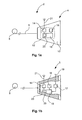
- FIG 1a shows apparatus 2 according to the invention, which apparatus 2 comprises a towed device 4, a linear retaining means 6 and an actuating device 8.
- the towed device 4 comprises an enclosure 10 which in order to protect against dirt, moisture and dynamic pressure encloses a grouped arrangement of electronic and mechanical devices 12.
- the term "towed device” 4 refers to the device, arranged on the retaining means 6, which is towed behind the aircraft. It is not imperative for this towed device 4 to comprise measuring devices as shown in the exemplary embodiments of Figures 1c and 1d .
- a pressure sensor 14 In the towed device 4 a pressure sensor 14, an energy storage device 16 as an autarchic voltage supply, and a first communication device 18 that is connected both to the energy storage device 16 and to the pressure sensor 14 are arranged.
- the first communication device 18 Preferably, apart from the actual provisions necessary for communication, the first communication device 18 also comprises an electronics unit 20 which processes signals or measured values of the pressure sensor 14 in such a manner that they can be transmitted in the form of data or signals to the outside to a further communication device.
- the first communication device 18 is a wireless communication device and is correspondingly connected to a transmitting and receiving antenna 21 that can be positioned at various positions inside or outside the enclosure 10. With corresponding dimensioning it would also be possible for the entire enclosure 10 to serve as an antenna for a predetermined narrow frequency range.
- the antenna 21 could also be bonded in the shape of a wire or the like onto the outer surface of the enclosure 10, wherein corresponding insulation is to be affixed between the antenna 21 and the enclosure 10.
- the antenna 21 could also be designed so as to be rigid and could extend away from the enclosure 10 or it could be implemented as a slack stranded wire, protruding from the enclosure 10, with a corresponding insulation sheath in the manner of a wire antenna.
- the first communication device 18 can, for example, be designed to implement data transmission by means of a frequency-spreading method which is insensitive to narrow-band interference.
- the linear retaining means 6 is used to pull the enclosure 10, together with the devices contained therein, behind an aircraft, wherein the linear retaining means 6 is exclusively equipped to exert a pulling force on the towed device 4, which pulling force results from the aerodynamic flow around the enclosure 10 and from the associated aerodynamic resistance or drag.
- the actuating device 8 is designed as a winch with a motorised winding roll or the like, which winding roll is equipped to roll in and roll out the linear retaining means 6 and in so doing to retract it from, or extend it to, an airstream present behind an aircraft.
- the towed device 4 can be removed from the movement means 8 in order to, in this manner, be able to measure a static pressure, for example at a predetermined distance from an aircraft, for example at 1-1.5 times the aircraft length.
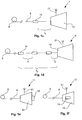
- Figure 1b shows a modified towed device 4 which in addition to the components shown in Fig. 1a also comprises a GPS receiver 17 that is connected to a GPS antenna 19 and to the first communication device 18.
- the GPS receiver 17 usually transmits GPS information at continuous intervals to the first communication device 18, which can use this information to transmit a geometric altitude to the aircraft, which geometric altitude has been determined by position finding.
- a barometric altitude determined in the aircraft can be correlated with the geographic altitude determined by position finding, or corresponding calibration of the barometric altitude display can be carried out.
- the GPS antenna 19 is preferably designed as a ceramic chip antenna, but it can at the same time also be designed as a separate antenna affixed to the enclosure 10, in particular if the enclosure 10 comprises a metallic material.
- the exemplary embodiment of Fig. 1b comprises a solar cell 23 as an autarchic voltage supply, which solar cell 23 could be arranged on the enclosure 12 and is connected to the first communication device 18.
- This can be in support of an energy storage device 16 which could be dimensioned so as to be correspondingly smaller, thus predominantly serving as a buffer storage device.
- the pressure sensor 14 is not arranged within the enclosure 10 of a towed device 7, but instead, when seen upstream, is spaced apart from the enclosure 10 by a distance l 1 so as to be free of any aerodynamic influences of the enclosure 10.
- the pressure sensor 14 is preferably wired to the first communication device 18, which is located within the enclosure 10. If the retaining means 6 comprises a metallic material, it could be used as part of the wiring.
- a multitude of pressure sensors 14 are arranged, so as to be spaced apart from each other, on the retaining means 6 upstream of the enclosure 10 of a towed device 9.
- the space d between the individual pressure sensors 14 is between 2 and 10 m, wherein the pressure sensors extend along a rear section of the retaining means 6, for example along a third.
- the overall length l 3 of this arrangement of pressure sensors 14 could, for example, be 50 m, with an overall length of the retaining means 6 of 150 m and a distance l 2 of, for example, less than 5 m from the enclosure 10.
- the pressure sensors 14 In the design of such an exemplary embodiment it is important to use particularly flat and compact pressure sensors 14 so that rolling-in the retaining means 6 is not negatively affected. Furthermore, the pressure sensors 14 must be wired to the first communication device 18 so that the determined measured values can be transmitted to the aircraft. This could take place by means of particularly fine wiring, wherein in the embodiment of the retaining means 6 as a thin wire cable the retaining means 6 could be used as a shared voltage supply terminal or the like for the pressure sensors 14.
- Figures 1e and 1f show further different positions of a pressure sensor 14.
- Fig. 1e for example, demonstrates a pressure sensor 14, arranged behind the enclosure 10, on a towed device 11, while in Fig. 1f the pressure sensor 14 is arranged on the outside of the enclosure 10 of a towed device 13.
- Figure 2 shows an overall system according to the present invention, which apart from the apparatus 2 also comprises a second communication device 24 with an antenna 22, furthermore also a regulating unit 26 that is designed to both control the actuating device 8 and to forward the data transmitted by the towed device 4 to at least one corresponding electronics device 28 within the aircraft.
- the second communication device 24 could preferably be equipped for initiating the communication with the first communication device 18 so that, in an existing connection, data is transmitted in packets to the second communication device 24.
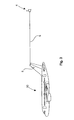
- Figure 3 shows an aircraft 30 with a system according to the invention, which system makes it possible for the aircraft 30 to extend the towed device 4 behind the aircraft 30 in order to determine a static air pressure in that location.
- the distance between the towed device 4 and the rear delimitation of the aircraft 30 could, for example, be 1-1.5 times the aircraft length.
- the apparatus according to the invention is arranged in a vertical stabiliser, particularly preferably in a front spar of the vertical stabiliser and/or in an end cap of the vertical stabiliser, wherein the linear retaining means 6 could be fed through an opening at an upper region of the vertical stabiliser above the rudder.
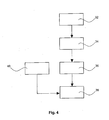
- Figure 4 shows a block diagram of a method according to the invention, which method essentially comprises the steps of: extending 32 a towed device 4; measuring 34 a static air pressure; transmitting 36 the measured air pressure to a second communication device 24; and retracting 38 the towed device.
- the method according to the invention could also comprise transmitting 40 geometric altitude data.
Landscapes
- Engineering & Computer Science (AREA)
- Physics & Mathematics (AREA)
- General Physics & Mathematics (AREA)
- Aviation & Aerospace Engineering (AREA)
- Computer Networks & Wireless Communication (AREA)
- Measuring Fluid Pressure (AREA)
- Arrangements For Transmission Of Measured Signals (AREA)
Claims (15)
- Vorrichtung zum Erfassen eines Luftdrucks, aufweisend- ein linienförmiges Haltemittel (6);- einen Schleppkörper (4, 5, 7, 9, 11, 13) mit einem Gehäuse (10);- mindestens einen Drucksensor (14) zum Erfassen eines statischen Luftdrucks; und- eine in einem Fluggerät positionierbare Betätigungseinrichtung (8) zum Ein- und Ausfahren des linienförmigen Haltemittels (6);dadurch gekennzeichnet, dass der Schleppkörper (4, 5, 7, 9, 11, 13) eine autarke Spannungsversorgung (16, 23) und eine mit der autarken Spannungsversorgung (16, 23) verbundene drahtlose erste Kommunikationseinrichtung (18) aufweist, wobei die erste Kommunikationseinrichtung dazu eingerichtet ist, Signale und/oder Daten, die erfasste Messdaten repräsentieren, an eine zweite Kommunikationseinrichtung (24) zu übertragen.
- Vorrichtung nach Anspruch 1, wobei die Betätigungseinrichtung (8) als eine Winde ausgeführt ist, die dazu eingerichtet ist, das linienförmige Haltemittel (8) einzuziehen oder auszufahren.
- Vorrichtung nach Anspruch 1 oder 2, wobei das linienförmige Haltemittel (8) als ein Kunststoffseil ausgeführt ist.
- Vorrichtung nach Anspruch 3, wobei das Kunststoffseil aus Polyamid hergestellt ist.
- Vorrichtung nach Anspruch 1 oder 2, wobei das linienförmige Haltemittel (8) als ein Drahtseil ausgeführt ist.
- Vorrichtung nach einem der vorhergehenden Ansprüche, wobei die autarke Spannungsversorgung (16, 23) zumindest teilweise als eine Energiespeichereinheit (16) ausgeführt ist.
- Vorrichtung nach einem der vorhergehenden Ansprüche, wobei die autarke Spannungsversorgung (16, 23) zumindest teilweise als Solarzelle (23) ausgeführt ist.
- Vorrichtung nach einem der vorhergehenden Ansprüche, ferner aufweisend einen GPS-Empfännger (17) und eine GPS-Antenne (19), die mit der ersten Kommunikationseinrichtung (16) zum Übertragen einer geographischen Höhe verbunden ist.
- Vorrichtung nach einem der vorhergehenden Ansprüche, aufweisend eine Mehrzahl von Drucksensoren (14), die an dem linienförmigen Haltemittel (8) angeordnet sind.
- System zum Erfassen von Luftdaten, aufweisend eine Vorrichtung zum Erfassen eines Luftdrucks nach einem der Ansprüche 1 bis 9 sowie eine zweite Kommunikationseinrichtung (24), die dazu eingerichtet ist, mit der ersten Kommunikationseinrichtung (18) zu kommunizieren und Signale und/oder Daten, die erfasste Messdaten repräsentieren, an ein in einem Fluggerät positionierbares Elektronikgerät (28) zu übertragen.
- Verfahren zum Messen eines statischen Luftdrucks, aufweisend die Schritte- Ausfahren (32) eines Schleppkörpers (4, 5, 7, 9, 11, 13) an einem linienförmigen Haltemittel (6) in eine Umgebung eines Fluggeräts;- Messen (34) eines statischen Luftdrucks mittels mindestens eines Drucksensors (14) an dem Schleppkörper und/oder dem linienförmigen Haltemittel (6);- Übertragen (36) des gemessenen Luftdrucks mittels einer drahtlosen ersten Kommunikationseinrichtung (18) an eine zweite Kommunikationseinrichtung (24) und- Einfahren (38) des Schleppkörpers.
- Verfahren nach Anspruch 11, ferner aufweisend- Übertragen von mittels eines GPS-Empfängers (17) bereitgestellten geographischen Höhendaten von der ersten Kommunikationseinrichtung (18) an die zweite Kommunikationseinrichtung (24).
- Verfahren nach Anspruch 12, ferner aufweisend
Korrelation einer gemessenen barometrischen Höhe an einem Fluggerät unter Verwendung einer durch den GPS-Empfänger (17) bestimmten geometrischen geographischen Höhe an dem Schleppkörper und einer geometrischen Höhe bestimmt in dem Fluggerät an einem Referenzpunkt mittels eines GPS-Empfängers an Bord des Fluggeräts. - Flugzeug mit mindestens einer Vorrichtung nach einem der Ansprüche 1 bis 9.
- Flugzeug nach Anspruch 14, wobei die Vorrichtung in einem Seitenleitwerk des Flugzeugs angeordnet ist und das Seitenleitwerk eine Öffnung zum Durchführen des linienförmigen Haltemittels aus dem Seitenleitwerk in eine das Flugzeug umgebende Strömung aufweist.
Applications Claiming Priority (3)
| Application Number | Priority Date | Filing Date | Title |
|---|---|---|---|
| US32877810P | 2010-04-28 | 2010-04-28 | |
| DE102010018547A DE102010018547A1 (de) | 2010-04-28 | 2010-04-28 | Vorrichtung und Verfahren zum Messen eines Luftdrucks sowie System zum Erfassen von Luftdaten |
| PCT/EP2011/056527 WO2011134931A1 (en) | 2010-04-28 | 2011-04-26 | Apparatus and method for measuring an air pressure and system for detecting air data |
Publications (2)
| Publication Number | Publication Date |
|---|---|
| EP2564599A1 EP2564599A1 (de) | 2013-03-06 |
| EP2564599B1 true EP2564599B1 (de) | 2014-07-30 |
Family
ID=44786303
Family Applications (1)
| Application Number | Title | Priority Date | Filing Date |
|---|---|---|---|
| EP11716532.4A Not-in-force EP2564599B1 (de) | 2010-04-28 | 2011-04-26 | Vorrichtung und verfahren zur messung eines luftdrucks und system zur erfassung von luftdaten |
Country Status (5)
| Country | Link |
|---|---|
| US (1) | US20130048782A1 (de) |
| EP (1) | EP2564599B1 (de) |
| CN (1) | CN102860035B (de) |
| DE (1) | DE102010018547A1 (de) |
| WO (1) | WO2011134931A1 (de) |
Families Citing this family (12)
| Publication number | Priority date | Publication date | Assignee | Title |
|---|---|---|---|---|
| US9324236B2 (en) * | 2011-11-23 | 2016-04-26 | The Boeing Company | System and methods for situation awareness, advisory, tracking, and aircraft control information |
| CN102853961B (zh) * | 2012-09-29 | 2014-06-11 | 西北工业大学 | 以拖锥为载体的飞机外置式空气静压测量装置 |
| FR3009281B1 (fr) * | 2013-07-31 | 2017-02-17 | Airbus Operations Sas | Aeronef comprenant un systeme de mesure de pression et procede associe |
| US9383381B2 (en) * | 2014-03-13 | 2016-07-05 | The Boeing Company | Airspeed calculation system for an aircraft |
| DE102014018857B4 (de) * | 2014-12-15 | 2017-10-05 | Alfred-Wegener-Institut Helmholtz-Zentrum für Polar- und Meeresforschung | Aerodynamisch geformter, aktiver Schleppkörper |
| BR112017020383A2 (pt) * | 2015-03-23 | 2018-06-05 | Gardini Luca | dispositivo de rede, rede de computador e metódo para controlar ambientes |
| CN105091851B (zh) * | 2015-04-24 | 2018-07-17 | 广东小天才科技有限公司 | 一种测量高度的方法及装置 |
| CN105300587B (zh) * | 2015-10-21 | 2018-03-27 | 沈阳旋飞航空技术有限公司 | 飞机便捷测压装置 |
| US10041792B2 (en) * | 2015-12-30 | 2018-08-07 | Qualcomm Incorporated | Pressure tap structures for barometric altimeters for unmanned aerial vehicles |
| JP7130397B2 (ja) * | 2018-03-19 | 2022-09-05 | 三菱航空機株式会社 | トレーリングコーンシステム |
| DE102018207009A1 (de) * | 2018-05-07 | 2019-11-07 | Deutsches Zentrum für Luft- und Raumfahrt e.V. | Vorrichtung zum Erfassen eines Luftzustandes und Sensornetzwerk |
| CN111830286B (zh) * | 2020-06-03 | 2022-07-22 | 福建水利电力职业技术学院 | 一种升降式三维流速计标定水槽及其标定流速的方法 |
Family Cites Families (26)
| Publication number | Priority date | Publication date | Assignee | Title |
|---|---|---|---|---|
| US2649262A (en) * | 1945-10-24 | 1953-08-18 | Delmer S Fahrney | Apparatus for remote control bombing |
| US4354419A (en) * | 1980-08-08 | 1982-10-19 | The United States Of America As Represented By The Secretary Of The Air Force | Survivable target acquisition and designation system |
| US4808999A (en) * | 1988-02-18 | 1989-02-28 | Loral Corp. | Towed decoy with fiber optic link |
| DE4013921C1 (en) * | 1990-04-30 | 1991-07-04 | Deutsche Airbus Gmbh, 2000 Hamburg, De | Air pressure measuring device for aeroplane - has infrared energy source e.g. laser diode with driver feeding converter e.g. solar cell and storage capacitor |
| US5136295A (en) * | 1991-05-14 | 1992-08-04 | The Boeing Company | Airborne fiber optic decoy architecture |
| US5260820A (en) * | 1991-05-14 | 1993-11-09 | Bull James G | Airborne fiber optic decoy architecture |
| US5188313A (en) * | 1992-01-03 | 1993-02-23 | Piasecki Aircraft Corporation | Glider aircraft tow control system |
| US5786786A (en) * | 1997-03-17 | 1998-07-28 | Raytheon Company | Photonic radar decoy |
| US5913280A (en) * | 1997-08-28 | 1999-06-22 | Petroleum Geo-Services (Us), Inc. | Method and system for towing multiple streamers |
| US6220543B1 (en) * | 1997-12-22 | 2001-04-24 | Alexander Uskolovsky | Safe and secure commercial air transportation |
| DE19852797C2 (de) * | 1998-11-16 | 2000-11-23 | Karlsruhe Forschzent | Aerologische Fallsonde |
| WO2001050135A2 (en) * | 1999-12-30 | 2001-07-12 | Advanced Aerospace Technologies, Inc. | Survivability and mission flexibility enhancements for reconnaissance aircraft |
| US6804495B2 (en) * | 2001-10-05 | 2004-10-12 | Northrop Grumman Corporation | Wireless communicator link from towed/surrogate decoy transmitter to the host aircraft |
| US6739232B2 (en) * | 2002-01-31 | 2004-05-25 | Sanmina-Sci Corporation | Towed airborne vehicle control and explosion damage assessment |
| US6932299B2 (en) * | 2003-10-15 | 2005-08-23 | The United States Of America As Represented By The Secretary Of The Air Force | Apparatus for aerial rearmament of aircraft |
| JP2005321658A (ja) * | 2004-05-10 | 2005-11-17 | International Display Technology Kk | 回路検査方法、液晶表示装置の製造方法および回路検査装置 |
| US7069147B2 (en) * | 2004-05-28 | 2006-06-27 | Honeywell International Inc. | Airborne based monitoring |
| DE202004013613U1 (de) * | 2004-08-30 | 2004-12-16 | Karrais, Berthold, Dipl.-Ing. | Radiosonden-Gleiter |
| CA2581193C (en) * | 2004-09-21 | 2016-04-12 | Fairfield Industries, Inc. | Method and apparatus for seismic data acquisition |
| DE102007015202A1 (de) * | 2007-03-27 | 2008-10-30 | Smolik, Ludek, Dr. rer. nat. | Vorrichtung für die Messung von Drücken in einem Fluid bei wechselnder Strömungsrichtung und bei einer turbulenten Strömung des Fluids |
| WO2009091792A2 (en) * | 2008-01-15 | 2009-07-23 | Sysense, Inc. | A methodology for autonomous navigation and control of a tethered drogue |
| AU2009294243A1 (en) * | 2008-09-19 | 2010-03-25 | Shilat Imaging Ltd | Aerial observation system |
| US8358967B1 (en) * | 2008-12-01 | 2013-01-22 | L-3 Communications | Towed network communications subsystem for in flight use by towing aircraft |
| US8366037B2 (en) * | 2009-05-22 | 2013-02-05 | Heliplane, Llc | Towable aerovehicle system with automated tow line release |
| US8540183B2 (en) * | 2009-12-12 | 2013-09-24 | Heliplane, Llc | Aerovehicle system including plurality of autogyro assemblies |
| US8646719B2 (en) * | 2010-08-23 | 2014-02-11 | Heliplane, Llc | Marine vessel-towable aerovehicle system with automated tow line release |
-
2010
- 2010-04-28 DE DE102010018547A patent/DE102010018547A1/de not_active Ceased
-
2011
- 2011-04-26 EP EP11716532.4A patent/EP2564599B1/de not_active Not-in-force
- 2011-04-26 CN CN201180020895.XA patent/CN102860035B/zh not_active Expired - Fee Related
- 2011-04-26 WO PCT/EP2011/056527 patent/WO2011134931A1/en not_active Ceased
-
2012
- 2012-10-25 US US13/660,216 patent/US20130048782A1/en not_active Abandoned
Also Published As
| Publication number | Publication date |
|---|---|
| DE102010018547A8 (de) | 2012-08-02 |
| EP2564599A1 (de) | 2013-03-06 |
| CN102860035A (zh) | 2013-01-02 |
| CN102860035B (zh) | 2015-06-24 |
| US20130048782A1 (en) | 2013-02-28 |
| DE102010018547A1 (de) | 2011-11-03 |
| WO2011134931A1 (en) | 2011-11-03 |
Similar Documents
| Publication | Publication Date | Title |
|---|---|---|
| EP2564599B1 (de) | Vorrichtung und verfahren zur messung eines luftdrucks und system zur erfassung von luftdaten | |
| CA2763745C (en) | Method and apparatus for wireless sensing with power harvesting of a wireless signal | |
| EP2759478B1 (de) | Spitze mit Düsenbelastungsmessung und drahtlose Kommunikationsfunktion für Luftbetankung | |
| EP2371039B1 (de) | Datensammlungsverbindung | |
| US11001157B2 (en) | Device including a supply line with a sensor line configured to measure a torsion of the supply line and a method for measuring the torsion of a supply line based on a capacitance of the sensor line | |
| JP2017504762A (ja) | 航空車両用ワイヤリングハーネス | |
| CN104344922B (zh) | 包括压力测量系统的飞行器和相关的压力测量方法 | |
| US20230384078A1 (en) | Systems, devices, and methods for unmanned power line diameter measurement | |
| EP2930037A1 (de) | Bugrad-reifendrucküberwachungssystem und vorrichtung | |
| US20030189434A1 (en) | Ice detection system | |
| KR101386630B1 (ko) | 내장형 밸런스의 과부하 방지장치, 이를 포함하는 풍동시험장치 및 방지장치의 대상시험장치 및 예비시험방법 | |
| CN217738413U (zh) | 搭载测重装置及飞行器 | |
| US10830657B2 (en) | Low profile pressure sensor on the body of a vehicle | |
| CA3031973A1 (en) | Fluid characterization system with integrated density compensation | |
| CN116835398A (zh) | 系留线缆的收放控制方法、收放控制装置及飞行器组件 | |
| CA2356802C (en) | In-flight calibration of air data systems using a nose-mask sensor | |
| CA3037238A1 (en) | Fluid measurement interface systems and methods | |
| JP6944848B2 (ja) | 発信装置 | |
| Bordogna et al. | MUSCAT experiment: Active free falling units for in situ measurements of temperature and density in the middle atmosphere | |
| GB2181848A (en) | Indicating glide path direction of parachutes | |
| Hang | AFRC Wireless Development Plans and Needs | |
| CN118205720A (zh) | 螺旋桨测试装置 | |
| CN112985728A (zh) | 无人机结构传递特性的测量装置和无人机 | |
| CN113567077A (zh) | 一种基于5g通信技术海上火箭发射平台冲击振动测试系统及其测试方法 | |
| TYAGI et al. | Performance data acquisition from flexible aerodynamic decelerators |
Legal Events
| Date | Code | Title | Description |
|---|---|---|---|
| PUAI | Public reference made under article 153(3) epc to a published international application that has entered the european phase |
Free format text: ORIGINAL CODE: 0009012 |
|
| 17P | Request for examination filed |
Effective date: 20121011 |
|
| AK | Designated contracting states |
Kind code of ref document: A1 Designated state(s): AL AT BE BG CH CY CZ DE DK EE ES FI FR GB GR HR HU IE IS IT LI LT LU LV MC MK MT NL NO PL PT RO RS SE SI SK SM TR |
|
| DAX | Request for extension of the european patent (deleted) | ||
| RIC1 | Information provided on ipc code assigned before grant |
Ipc: G01P 5/16 20060101ALI20131118BHEP Ipc: G01L 19/08 20060101ALI20131118BHEP Ipc: H04Q 9/00 20060101AFI20131118BHEP Ipc: G01P 21/02 20060101ALI20131118BHEP |
|
| GRAP | Despatch of communication of intention to grant a patent |
Free format text: ORIGINAL CODE: EPIDOSNIGR1 |
|
| INTG | Intention to grant announced |
Effective date: 20140207 |
|
| RIN1 | Information on inventor provided before grant (corrected) |
Inventor name: CAMMAS, JEAN Inventor name: BOHLEN, HOLGER Inventor name: BLUNCK, CARSTEN Inventor name: BOHLEN, CARSTEN |
|
| GRAS | Grant fee paid |
Free format text: ORIGINAL CODE: EPIDOSNIGR3 |
|
| GRAA | (expected) grant |
Free format text: ORIGINAL CODE: 0009210 |
|
| AK | Designated contracting states |
Kind code of ref document: B1 Designated state(s): AL AT BE BG CH CY CZ DE DK EE ES FI FR GB GR HR HU IE IS IT LI LT LU LV MC MK MT NL NO PL PT RO RS SE SI SK SM TR |
|
| REG | Reference to a national code |
Ref country code: GB Ref legal event code: FG4D |
|
| REG | Reference to a national code |
Ref country code: CH Ref legal event code: EP |
|
| REG | Reference to a national code |
Ref country code: AT Ref legal event code: REF Ref document number: 680457 Country of ref document: AT Kind code of ref document: T Effective date: 20140815 |
|
| REG | Reference to a national code |
Ref country code: IE Ref legal event code: FG4D |
|
| REG | Reference to a national code |
Ref country code: DE Ref legal event code: R096 Ref document number: 602011008734 Country of ref document: DE Effective date: 20140911 |
|
| REG | Reference to a national code |
Ref country code: AT Ref legal event code: MK05 Ref document number: 680457 Country of ref document: AT Kind code of ref document: T Effective date: 20140730 |
|
| REG | Reference to a national code |
Ref country code: NL Ref legal event code: VDEP Effective date: 20140730 |
|
| REG | Reference to a national code |
Ref country code: LT Ref legal event code: MG4D |
|
| PG25 | Lapsed in a contracting state [announced via postgrant information from national office to epo] |
Ref country code: ES Free format text: LAPSE BECAUSE OF FAILURE TO SUBMIT A TRANSLATION OF THE DESCRIPTION OR TO PAY THE FEE WITHIN THE PRESCRIBED TIME-LIMIT Effective date: 20140730 Ref country code: BG Free format text: LAPSE BECAUSE OF FAILURE TO SUBMIT A TRANSLATION OF THE DESCRIPTION OR TO PAY THE FEE WITHIN THE PRESCRIBED TIME-LIMIT Effective date: 20141030 Ref country code: SE Free format text: LAPSE BECAUSE OF FAILURE TO SUBMIT A TRANSLATION OF THE DESCRIPTION OR TO PAY THE FEE WITHIN THE PRESCRIBED TIME-LIMIT Effective date: 20140730 Ref country code: FI Free format text: LAPSE BECAUSE OF FAILURE TO SUBMIT A TRANSLATION OF THE DESCRIPTION OR TO PAY THE FEE WITHIN THE PRESCRIBED TIME-LIMIT Effective date: 20140730 Ref country code: PT Free format text: LAPSE BECAUSE OF FAILURE TO SUBMIT A TRANSLATION OF THE DESCRIPTION OR TO PAY THE FEE WITHIN THE PRESCRIBED TIME-LIMIT Effective date: 20141202 Ref country code: LT Free format text: LAPSE BECAUSE OF FAILURE TO SUBMIT A TRANSLATION OF THE DESCRIPTION OR TO PAY THE FEE WITHIN THE PRESCRIBED TIME-LIMIT Effective date: 20140730 Ref country code: GR Free format text: LAPSE BECAUSE OF FAILURE TO SUBMIT A TRANSLATION OF THE DESCRIPTION OR TO PAY THE FEE WITHIN THE PRESCRIBED TIME-LIMIT Effective date: 20141031 Ref country code: NO Free format text: LAPSE BECAUSE OF FAILURE TO SUBMIT A TRANSLATION OF THE DESCRIPTION OR TO PAY THE FEE WITHIN THE PRESCRIBED TIME-LIMIT Effective date: 20141030 |
|
| PG25 | Lapsed in a contracting state [announced via postgrant information from national office to epo] |
Ref country code: RS Free format text: LAPSE BECAUSE OF FAILURE TO SUBMIT A TRANSLATION OF THE DESCRIPTION OR TO PAY THE FEE WITHIN THE PRESCRIBED TIME-LIMIT Effective date: 20140730 Ref country code: CY Free format text: LAPSE BECAUSE OF FAILURE TO SUBMIT A TRANSLATION OF THE DESCRIPTION OR TO PAY THE FEE WITHIN THE PRESCRIBED TIME-LIMIT Effective date: 20140730 Ref country code: AT Free format text: LAPSE BECAUSE OF FAILURE TO SUBMIT A TRANSLATION OF THE DESCRIPTION OR TO PAY THE FEE WITHIN THE PRESCRIBED TIME-LIMIT Effective date: 20140730 Ref country code: HR Free format text: LAPSE BECAUSE OF FAILURE TO SUBMIT A TRANSLATION OF THE DESCRIPTION OR TO PAY THE FEE WITHIN THE PRESCRIBED TIME-LIMIT Effective date: 20140730 Ref country code: IS Free format text: LAPSE BECAUSE OF FAILURE TO SUBMIT A TRANSLATION OF THE DESCRIPTION OR TO PAY THE FEE WITHIN THE PRESCRIBED TIME-LIMIT Effective date: 20141130 Ref country code: PL Free format text: LAPSE BECAUSE OF FAILURE TO SUBMIT A TRANSLATION OF THE DESCRIPTION OR TO PAY THE FEE WITHIN THE PRESCRIBED TIME-LIMIT Effective date: 20140730 Ref country code: NL Free format text: LAPSE BECAUSE OF FAILURE TO SUBMIT A TRANSLATION OF THE DESCRIPTION OR TO PAY THE FEE WITHIN THE PRESCRIBED TIME-LIMIT Effective date: 20140730 Ref country code: LV Free format text: LAPSE BECAUSE OF FAILURE TO SUBMIT A TRANSLATION OF THE DESCRIPTION OR TO PAY THE FEE WITHIN THE PRESCRIBED TIME-LIMIT Effective date: 20140730 |
|
| REG | Reference to a national code |
Ref country code: FR Ref legal event code: PLFP Year of fee payment: 5 |
|
| PG25 | Lapsed in a contracting state [announced via postgrant information from national office to epo] |
Ref country code: RO Free format text: LAPSE BECAUSE OF FAILURE TO SUBMIT A TRANSLATION OF THE DESCRIPTION OR TO PAY THE FEE WITHIN THE PRESCRIBED TIME-LIMIT Effective date: 20140730 Ref country code: IT Free format text: LAPSE BECAUSE OF FAILURE TO SUBMIT A TRANSLATION OF THE DESCRIPTION OR TO PAY THE FEE WITHIN THE PRESCRIBED TIME-LIMIT Effective date: 20140730 Ref country code: DK Free format text: LAPSE BECAUSE OF FAILURE TO SUBMIT A TRANSLATION OF THE DESCRIPTION OR TO PAY THE FEE WITHIN THE PRESCRIBED TIME-LIMIT Effective date: 20140730 Ref country code: EE Free format text: LAPSE BECAUSE OF FAILURE TO SUBMIT A TRANSLATION OF THE DESCRIPTION OR TO PAY THE FEE WITHIN THE PRESCRIBED TIME-LIMIT Effective date: 20140730 Ref country code: SK Free format text: LAPSE BECAUSE OF FAILURE TO SUBMIT A TRANSLATION OF THE DESCRIPTION OR TO PAY THE FEE WITHIN THE PRESCRIBED TIME-LIMIT Effective date: 20140730 Ref country code: CZ Free format text: LAPSE BECAUSE OF FAILURE TO SUBMIT A TRANSLATION OF THE DESCRIPTION OR TO PAY THE FEE WITHIN THE PRESCRIBED TIME-LIMIT Effective date: 20140730 |
|
| REG | Reference to a national code |
Ref country code: DE Ref legal event code: R097 Ref document number: 602011008734 Country of ref document: DE |
|
| PLBE | No opposition filed within time limit |
Free format text: ORIGINAL CODE: 0009261 |
|
| STAA | Information on the status of an ep patent application or granted ep patent |
Free format text: STATUS: NO OPPOSITION FILED WITHIN TIME LIMIT |
|
| 26N | No opposition filed |
Effective date: 20150504 |
|
| PG25 | Lapsed in a contracting state [announced via postgrant information from national office to epo] |
Ref country code: MC Free format text: LAPSE BECAUSE OF FAILURE TO SUBMIT A TRANSLATION OF THE DESCRIPTION OR TO PAY THE FEE WITHIN THE PRESCRIBED TIME-LIMIT Effective date: 20140730 Ref country code: SI Free format text: LAPSE BECAUSE OF FAILURE TO SUBMIT A TRANSLATION OF THE DESCRIPTION OR TO PAY THE FEE WITHIN THE PRESCRIBED TIME-LIMIT Effective date: 20140730 Ref country code: LU Free format text: LAPSE BECAUSE OF FAILURE TO SUBMIT A TRANSLATION OF THE DESCRIPTION OR TO PAY THE FEE WITHIN THE PRESCRIBED TIME-LIMIT Effective date: 20150426 |
|
| REG | Reference to a national code |
Ref country code: CH Ref legal event code: PL |
|
| REG | Reference to a national code |
Ref country code: IE Ref legal event code: MM4A |
|
| PG25 | Lapsed in a contracting state [announced via postgrant information from national office to epo] |
Ref country code: CH Free format text: LAPSE BECAUSE OF NON-PAYMENT OF DUE FEES Effective date: 20150430 Ref country code: LI Free format text: LAPSE BECAUSE OF NON-PAYMENT OF DUE FEES Effective date: 20150430 |
|
| REG | Reference to a national code |
Ref country code: FR Ref legal event code: PLFP Year of fee payment: 6 |
|
| PG25 | Lapsed in a contracting state [announced via postgrant information from national office to epo] |
Ref country code: IE Free format text: LAPSE BECAUSE OF NON-PAYMENT OF DUE FEES Effective date: 20150426 |
|
| PG25 | Lapsed in a contracting state [announced via postgrant information from national office to epo] |
Ref country code: BE Free format text: LAPSE BECAUSE OF FAILURE TO SUBMIT A TRANSLATION OF THE DESCRIPTION OR TO PAY THE FEE WITHIN THE PRESCRIBED TIME-LIMIT Effective date: 20140730 |
|
| PGFP | Annual fee paid to national office [announced via postgrant information from national office to epo] |
Ref country code: DE Payment date: 20160421 Year of fee payment: 6 Ref country code: GB Payment date: 20160421 Year of fee payment: 6 |
|
| PGFP | Annual fee paid to national office [announced via postgrant information from national office to epo] |
Ref country code: FR Payment date: 20160421 Year of fee payment: 6 |
|
| PG25 | Lapsed in a contracting state [announced via postgrant information from national office to epo] |
Ref country code: MT Free format text: LAPSE BECAUSE OF FAILURE TO SUBMIT A TRANSLATION OF THE DESCRIPTION OR TO PAY THE FEE WITHIN THE PRESCRIBED TIME-LIMIT Effective date: 20140730 |
|
| REG | Reference to a national code |
Ref country code: DE Ref legal event code: R082 Ref document number: 602011008734 Country of ref document: DE Representative=s name: LKGLOBAL | LORENZ & KOPF PARTG MBB PATENTANWAE, DE Ref country code: DE Ref legal event code: R082 Ref document number: 602011008734 Country of ref document: DE Representative=s name: KOPF WESTENBERGER WACHENHAUSEN PATENTANWAELTE , DE |
|
| PG25 | Lapsed in a contracting state [announced via postgrant information from national office to epo] |
Ref country code: SM Free format text: LAPSE BECAUSE OF FAILURE TO SUBMIT A TRANSLATION OF THE DESCRIPTION OR TO PAY THE FEE WITHIN THE PRESCRIBED TIME-LIMIT Effective date: 20140730 Ref country code: HU Free format text: LAPSE BECAUSE OF FAILURE TO SUBMIT A TRANSLATION OF THE DESCRIPTION OR TO PAY THE FEE WITHIN THE PRESCRIBED TIME-LIMIT; INVALID AB INITIO Effective date: 20110426 |
|
| PG25 | Lapsed in a contracting state [announced via postgrant information from national office to epo] |
Ref country code: TR Free format text: LAPSE BECAUSE OF FAILURE TO SUBMIT A TRANSLATION OF THE DESCRIPTION OR TO PAY THE FEE WITHIN THE PRESCRIBED TIME-LIMIT Effective date: 20140730 |
|
| REG | Reference to a national code |
Ref country code: DE Ref legal event code: R119 Ref document number: 602011008734 Country of ref document: DE |
|
| GBPC | Gb: european patent ceased through non-payment of renewal fee |
Effective date: 20170426 |
|
| REG | Reference to a national code |
Ref country code: FR Ref legal event code: ST Effective date: 20171229 |
|
| PG25 | Lapsed in a contracting state [announced via postgrant information from national office to epo] |
Ref country code: DE Free format text: LAPSE BECAUSE OF NON-PAYMENT OF DUE FEES Effective date: 20171103 Ref country code: FR Free format text: LAPSE BECAUSE OF NON-PAYMENT OF DUE FEES Effective date: 20170502 |
|
| PG25 | Lapsed in a contracting state [announced via postgrant information from national office to epo] |
Ref country code: GB Free format text: LAPSE BECAUSE OF NON-PAYMENT OF DUE FEES Effective date: 20170426 |
|
| PG25 | Lapsed in a contracting state [announced via postgrant information from national office to epo] |
Ref country code: MK Free format text: LAPSE BECAUSE OF FAILURE TO SUBMIT A TRANSLATION OF THE DESCRIPTION OR TO PAY THE FEE WITHIN THE PRESCRIBED TIME-LIMIT Effective date: 20140730 |
|
| PG25 | Lapsed in a contracting state [announced via postgrant information from national office to epo] |
Ref country code: AL Free format text: LAPSE BECAUSE OF FAILURE TO SUBMIT A TRANSLATION OF THE DESCRIPTION OR TO PAY THE FEE WITHIN THE PRESCRIBED TIME-LIMIT Effective date: 20140730 |