EP2564012B1 - Verfahren und werkzeug zur herstellung eines pdc-erfassungselements - Google Patents
Verfahren und werkzeug zur herstellung eines pdc-erfassungselements Download PDFInfo
- Publication number
- EP2564012B1 EP2564012B1 EP11777913.2A EP11777913A EP2564012B1 EP 2564012 B1 EP2564012 B1 EP 2564012B1 EP 11777913 A EP11777913 A EP 11777913A EP 2564012 B1 EP2564012 B1 EP 2564012B1
- Authority
- EP
- European Patent Office
- Prior art keywords
- transducer
- drill bit
- sensor
- cutting element
- rotary drill
- Prior art date
- Legal status (The legal status is an assumption and is not a legal conclusion. Google has not performed a legal analysis and makes no representation as to the accuracy of the status listed.)
- Active
Links
Images







Classifications
-
- E—FIXED CONSTRUCTIONS
- E21—EARTH OR ROCK DRILLING; MINING
- E21B—EARTH OR ROCK DRILLING; OBTAINING OIL, GAS, WATER, SOLUBLE OR MELTABLE MATERIALS OR A SLURRY OF MINERALS FROM WELLS
- E21B47/00—Survey of boreholes or wells
-
- E—FIXED CONSTRUCTIONS
- E21—EARTH OR ROCK DRILLING; MINING
- E21B—EARTH OR ROCK DRILLING; OBTAINING OIL, GAS, WATER, SOLUBLE OR MELTABLE MATERIALS OR A SLURRY OF MINERALS FROM WELLS
- E21B10/00—Drill bits
- E21B10/08—Roller bits
-
- E—FIXED CONSTRUCTIONS
- E21—EARTH OR ROCK DRILLING; MINING
- E21B—EARTH OR ROCK DRILLING; OBTAINING OIL, GAS, WATER, SOLUBLE OR MELTABLE MATERIALS OR A SLURRY OF MINERALS FROM WELLS
- E21B10/00—Drill bits
- E21B10/46—Drill bits characterised by wear resisting parts, e.g. diamond inserts
- E21B10/56—Button-type inserts
- E21B10/567—Button-type inserts with preformed cutting elements mounted on a distinct support, e.g. polycrystalline inserts
-
- E—FIXED CONSTRUCTIONS
- E21—EARTH OR ROCK DRILLING; MINING
- E21B—EARTH OR ROCK DRILLING; OBTAINING OIL, GAS, WATER, SOLUBLE OR MELTABLE MATERIALS OR A SLURRY OF MINERALS FROM WELLS
- E21B47/00—Survey of boreholes or wells
- E21B47/01—Devices for supporting measuring instruments on drill bits, pipes, rods or wirelines; Protecting measuring instruments in boreholes against heat, shock, pressure or the like
- E21B47/013—Devices specially adapted for supporting measuring instruments on drill bits
-
- Y—GENERAL TAGGING OF NEW TECHNOLOGICAL DEVELOPMENTS; GENERAL TAGGING OF CROSS-SECTIONAL TECHNOLOGIES SPANNING OVER SEVERAL SECTIONS OF THE IPC; TECHNICAL SUBJECTS COVERED BY FORMER USPC CROSS-REFERENCE ART COLLECTIONS [XRACs] AND DIGESTS
- Y10—TECHNICAL SUBJECTS COVERED BY FORMER USPC
- Y10T—TECHNICAL SUBJECTS COVERED BY FORMER US CLASSIFICATION
- Y10T29/00—Metal working
- Y10T29/49—Method of mechanical manufacture
- Y10T29/49002—Electrical device making
Definitions
- This disclosure relates in general to Polycrystalline Diamond Compact drill bits, and in particular, to a method of and an apparatus for PDC bits with integrated sensors and methods for making such PDC bits.
- Rotary drill bits are commonly used for drilling bore holes, or well bores, in earth formations.
- Rotary drill bits include two primary configurations and combinations thereof.
- One configuration is the roller cone bit, which typically includes three roller cones mounted on support legs that extend from a bit body. Each roller cone is configured to spin or rotate on a support leg. Teeth are provided on the outer surfaces of each roller cone for cutting rock and other earth formations.
- a second primary configuration of a rotary drill bit is the fixed-cutter bit (often referred to as a "drag" bit), which conventionally includes a plurality of cutting elements secured to a face region of a bit body.
- the cutting elements of a fixed-cutter type drill bit have either a disk shape or a substantially cylindrical shape.
- a hard, superabrasive material such as mutually bonded particles of polycrystalline diamond, may be provided on a substantially circular end surface of each cutting element to provide a cutting surface.
- Such cutting elements are often referred to as "polycrystalline diamond compact” (PDC) cutters.
- the cutting elements may be fabricated separately from the bit body and are secured within pockets formed in the outer surface of the bit body.
- a bonding material such as an adhesive or a braze alloy may be used to secure the cutting elements to the bit body.
- the fixed-cutter drill bit may be placed in a bore hole such that the cutting elements abut against the earth formation to be drilled. As the drill bit is rotated, the cutting elements engage and shear away the surface of the underlying formation.
- MWD measurement while drilling
- LWD logging while drilling
- BHA bottom hole assembly
- EP0559286 discloses a formation evolution tool having a PDC cutting element.
- the present disclosure is directed towards a drill bit having PDC cutting elements including integrated circuits configured to measure drilling conditions, properties of fluids in the borehole, properties of earth formations, and/or properties of fluids in earth formations.
- PDC cutting elements including integrated circuits configured to measure drilling conditions, properties of fluids in the borehole, properties of earth formations, and/or properties of fluids in earth formations.
- the present invention provides a rotary drill bit as claimed in claim 1.
- the present invention also provides a method of conducting drilling operations as claimed in claim 3.
- the present invention also provides a method of forming a rotary drill bit as claimed in claim 11.
- the preferred method includes: making at least one polycrystalline diamond compact (PDC) cutter including: (i) at least one cutting element, (ii) at least one transducer configured to provide a signal indicative of at least one of: (I) an operating condition of the drill bit, and (II) a property of a fluid in the borehole, and (III) a property of the formation and (iii) a protective layer on a side of the at least one transducer opposite to the at least one cutting element; and using the protective layer for protecting a sensing layer including the at least one transducer from abrasion.
- PDC polycrystalline diamond compact
- the drill bit 10 includes a bit body 12 comprising a particle-matrix composite material 15 that includes a plurality of hard phase particles or regions dispersed throughout a low-melting point binder material.
- the hard phase particles or regions are "hard" in the sense that they are relatively harder than the surrounding binder material.
- the bit body 12 may be predominantly comprised of the particle-matrix composite material 15, which is described in further detail below.
- the bit body 12 may be fastened to a metal shank 20, which may be formed from steel and may include an American Petroleum Institute (API) threaded pin 28 for attaching the drill bit 10 to a drill string (not shown).
- API American Petroleum Institute
- the bit body 12 may be secured directly to the shank 20 by, for example, using one or more retaining members 46 in conjunction with brazing and/or welding, as discussed in further detail below.
- the bit body 12 may include wings or blades 30 that are separated from one another by junk slots 32.
- Internal fluid passageways 42 may extend between the face 18 of the bit body 12 and a longitudinal bore 40, which extends through the steel shank 20 and at least partially through the bit body 12.
- nozzle inserts (not shown) may be provided at the face 18 of the bit body 12 within the internal fluid passageways 42.
- the drill bit 10 may include a plurality of cutting elements on the face 18 thereof.
- a plurality of polycrystalline diamond compact (PDC) cutters 34 may be provided on each of the blades 30, as shown in Fig. 1 .
- the PDC cutters 34 may be provided along the blades 30 within pockets 36 formed in the face 18 of the bit body 12, and may be supported from behind by buttresses 38, which may be integrally formed with the bit body 12.
- the drill bit 10 may be positioned at the bottom of a well bore and rotated while drilling fluid is pumped to the face 18 of the bit body 12 through the longitudinal bore 40 and the internal fluid passageways 42.
- the formation cuttings and detritus are mixed with and suspended within the drilling fluid, which passes through the junk slots 32 and the annular space between the well bore hole and the drill string to the surface of the earth formation.
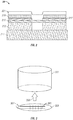
- FIG. 2 a cross section of an exemplary PDC cutter 34 is shown.
- This includes a PDC cutting element 213.
- This may also be referred to as part of the diamond table.
- a thin layer 215 of material such as Si 3 N 4 /Al 2 O 3 is provided for passivation/adhesion of other elements of the cutter 34 to the cutting elements 213.
- Chemical mechanical polishing (CMP) may be used for the upper surface of the passivation layer 215.
- the cutting element may be provided with a substrate 211.
- the layer 217 includes metal traces and patterns for the electrical circuitry associated with a sensor.
- a layer or plurality of layers 219 may include a piezoelectric element and a p-n-p transistor. These elements may be set up as a Wheatstone bridge for making measurements.
- the top layer 221 is a protective (passivation) layer that is conformal.
- the conformal layer 221 makes it possible uniformly cover 217 and/or 219 with a protective layer.
- the layer 221 may be made of diamond like carbon (DLC).
- the sensing material shown above is a piezoelectric material.
- the use of the piezoelectric material makes it possible to measure the strain on the cutter 34 during drilling operations.
- This is not to be construed as a limitation and a variety of sensors may be incorporated into the layer 219.
- an array of electrical pads to measure the electrical potential of the adjoining formation or to investigate highfrequency (HF) attenuation may be used.
- an array of ultrasonic transducers for acoustic imaging, acoustic velocity determination, acoustic attenuation determination, and shear wave propagation may be used.
- Sensors for other physical properties may be used. These include accelerometers, gyroscopes and inclinometers. Micro electro mechanical system (MEMS) or nano electro mechanical system (NEMS) style sensors and related signal conditioning circuitry can be built directly inside the PDC or on the surface. These are examples of sensors for a physical condition of the cutter and drillstem.
- MEMS Micro electro mechanical system
- NEMS nano electro mechanical system
- Chemical sensors that can be incorporated include sensors for elemental analysis: carbon nanotube (CNT), complementary metal oxide semiconductor (CMOS) sensors to detect the presence of various trace elements based on the principle of a selectively gated field effect transistors (FET) or ion sensitive field effect transistors (ISFET) for pH, H 2 S and other ions; sensors for hydrocarbon analysis; CNT, DLC based sensors working on chemical electropotential; and sensors for carbon/oxygen analysis.
- CNT carbon nanotube
- CMOS complementary metal oxide semiconductor
- FET selectively gated field effect transistors
- ISFET ion sensitive field effect transistors
- Acoustic sensors for acoustic imaging of the rock may be provided.
- transducers For the purposes of the present disclosure, all of these types of sensors may be referred to as transducers.
- the broad dictionary meaning of the term is intended: "a device actuated by power from one system and supplying power in the same or any other form to a second system.” This includes sensors that provide an electric signal in response to a measurement such as radiation as well as a device that uses electric power to produce mechanical motion.
- a sensor pad 303 provided with an array of sensing elements 305 is shown.
- the sensing elements may include pressure sensors, temperature sensors, stress sensors and/or strain sensors. Using the array of sensors, it is possible to make measurements of variations of the fence parameter across the face of the PDC element 301. Electrical leads 307 to the sensing array are shown.
- the pad 303 may be glued onto the PDC element 301 as indicated by the arrow 309.
- a sensor 419 is shown on the cutter 34.
- the sensor may be a chemical field effect transistor (FET).
- FET chemical field effect transistor
- the PDC element 413 is provided with grooves to allow fluid and particle flow to the sensor 419.
- the sensor 419 may comprise an acoustic transducer configured to measure the acoustic velocity of the fluids and particles in the grooves.
- the acoustic sensors may be built from thin films or may be made of piezoelectric elements.
- the sensing layer can be built on top of the diamond table or below the diamond table or on the substrate surface, (either of the interfaces with the diamond table or with the drill bit matrix).
- the sensor 419 may include an array of sensors of the type discussed above with reference to Fig. 3 .
- a bit body 12 with cutters 34 shown therein is a bit body 12 with cutters 34.
- a sensor 501 is shown disposed in a cavity 503 in the bit body 12.
- a communication (inflow) channel 505 is provided for flow of fluids and/or particles to the sensor 503.
- the cavity is also provided with an outlet channel 507.
- the sensor 501 is similar to the sensor shown in Fig. 2 but lacks the cutting elements 213 but includes the circuit layer 215, and the sensor layer 217.
- the sensor may include a chemical analysis sensor, an inertial sensor; an electrical potential sensor; a magnetic flux sensor and/or an acoustic sensor.
- the sensor is configured to make a measurement of a property of the fluid conveyed to the cavity and/or solid material in the fluid.
- Fig. 5 (b) shows the arrangement of the sensor 217 discussed in Fig. 2 .
- the sensor 217 is in the cutting element 213.
- Fig. 5 (d) shows the sensor 217 in the substrate and
- Fig. 5 (e) shows one sensor in the matrix 30 and one sensor in the substrate 211.
- Fig. 5f shows an arrangement in which nanotube sensors 501 are embedded in the matrix. These nanotubes may be used to measure pressure force and/ or temperature.
- Fig. 6 shows an antenna 601 on the cutter 34.
- An electromagnetic (EM) transceiver 603 is located in the matrix of the bit body 12. The transceiver is used to interrogate the antenna 601 and retrieve data on the measurements made by the sensor 219 in Fig. 2 .
- the transceiver is provided with electrically shielded cables to enable communication with devices in the bit shank or a sub attached to the drill bit.
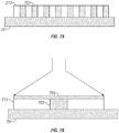
- FIG. 7(a) - (e) the sequence of operations used to assemble the cutter 34 shown in Fig. 2 are discussed.
- PDC elements 213 are mounted on a handle wafer 701 to form a diamond table.
- Filler material 703 is added to make the upper surface of the subassembly shown in Fig. 7(a) planar.
- a "passivation layer” 705 comprising Si 3 N 4 may be deposited on top of the cutter elements 213 and the filler 703.
- the purpose of the thin layer is to improve adhesion between the cutter elements 213 and the layer above (discussed with reference to Fig. 7a ).
- this layer also prevents damage to the layer above by the PDC cutting element 213.
- Chemical mechanical polishing (CMP) may be needed for forming the passivation layer.
- CMP Chemical mechanical polishing
- Si 3 N 4 is for exemplary purposes and not to be construed as a limitation.
- Equipment for chemical vapor deposition (CVD), Physical/Plasma Vapor Deposition (PVD), low pressure chemical vapor deposition (LPCVD), atomic layer deposition (ALD), and sol-gel spinning may be needed at this stage.
- metal traces and a pattern 709 for contacts and electronic circuitry are deposited.
- Equipment for sputter coating, evaporation, ALD, electroplating, and etching may be used.
- a piezoelectric material and a p-n-p semiconductor layer 709 are deposited.
- the output of the piezoelectric material may be used as an indication of strain when the underlying pattern on layer 707 includes a Wheatstone bridge. It should be noted that the use of a piezoelectric material is for exemplary purposes only and other types of sensor materials could be used.
- Equipment needed for this may include LPCVD, CVD, Plasma, ALD and RF sputtering.
- a protective passivation layer that is conformal is added 711.
- conformal is used to mean the ability to form a layer over a layer of varying topology. This could be made of diamond -like carbon (DLC). Process equipment needed may include CVD, sintering, and RF sputtering. Removal of the handle 701 and the filler material gives the PDC cutter 34 shown in Fig. 2 that may be attached to the wing 30 in Fig. 1 .
- Fig. 8a shows the major operational units needed to provide the mounted PDC unit of Fig. 7b . This includes starting with the PDC elements 213 in step 801 and the handle wafer 701 in 803 to give the mounted and planarized unit 805.
- the mounted PDC unit is transferred to a PDC loading unit 811 and goes to a PDC wafer transfer unit 813.
- the units are then transferred to the units identified as 815, 817 and 819.
- 815 is the metal processing chamber which may include CVD, sputtering and evaporation.
- the thin film deposition chamber 819 may includes LPCVD, CVD, and plasma enhanced CVD.
- the DLC deposition chamber 817 may include CVD and ALD.
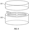
- tungsten carbide base 905 is shown with sensors 903 and a PDC table.
- One method of fabrication comprises deposition of the sensing layer 903 directly on top of the tungsten carbide base 905 and then forming the diamond table on top of the tungsten carbide base. Temperatures of 1500°C to 1700°C may be used and pressures of around 10 6 psi may be used.
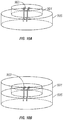
- Such an assembly can be fabricated by building a sensing layer 903 on the substrate 905 and running traces 904 as shown i n Fig. 10(a) .
- the diamond table 901 is next deposited on the substrate.
- the diamond table 901 may be preformed, based on the substrate 905, and brazed.
- Fig. 5f Fabrication of the assembly shown in Fig. 5f is discussed next with reference to Figs. 11 (a) -(b).
- the nanotubes 1103 are inserted into the substrate 905.
- the diamond table 901 is next deposited on the substrate 905.
- Integrating temperature sensors in the assemblies of Figs. 10-11 is relatively straightforward. Possible materials to be used are high-temperature thermocouple materials. Connection may be provided through the side of the PDC or through the bottom of the PDC.
- Pressure sensors made of quartz crystals can be embedded in the substrate. Piezoelectric materials may be used. Resistivity and capacitive measurements can be performed through the diamond table by placing electrodes on the tungsten carbide substrate. Magnetic sensors can be integrated for failure magnetic surveys. Those versed in the art and having benefit of the present disclosure would recognize that magnetic material would have to be re-magnetized after integrating into the sensor assembly. Chemical sensors may also be used in the configuration of Fig. 11 . Specifically, a small source of radioactive materials is used in or instead of one of the nanotubes and a gamma ray sensor or a neutron sensor may be used in the position of another one of the nanotubes.
- the piezoelectric transducer could also be used to generate acoustic vibrations.
- Such ultrasonic transducers may be used to keep the face of the PDC element clean and to increase the drilling efficiency.
- Such a transducer may be referred to as a vibrator.
- the ability to generate elastic waves in the formation can provide much useful information. This is schematically illustrated in Fig. 12 that shows acoustic transducers on two different PDC elements 34. One of them, for example 1201 may be used to generate a shear wave in the formation. The shear wave propagating through the formation is detected by the transducer 1203 at a known distance from the source transducer 1201.
- the formation shear velocity can be estimated. This is a good diagnostic of the rock type. Measurement of the decay of the shear wave over a plurality of distances provides an additional indication of the rock type.
- compressional wave velocity measurements are also made. The ratio of compressional wave velocity to shear wave velocity (V P /V S ratio) helps distinguish between carbonate rocks and siliciclastic rocks. The presence of gas can also be detected using measurements of the V P /V S ratio.
- the condition of the cutting element may be determined from the propagation velocity of surface waves on the cutting element. This is an example of determination of the operating condition of the drill bit.
- the shear waves may be generated using an electromagnetic acoustic transducer (EMAT).
- EMAT electromagnetic acoustic transducer
- the acquisition and processing of measurements made by the transducer may be controlled at least in part by downhole electronics (not shown). Implicit in the control and processing of the data is the use of a computer program on a suitable machine readable-medium that enables the processors to perform the control and processing.
- the machine-readable medium may include ROMs, EPROMs, EEPROMs, flash memories and optical disks.
- the term processor is intended to include devices such as a field programmable gate array (FPGA).
Landscapes
- Engineering & Computer Science (AREA)
- Geology (AREA)
- Mining & Mineral Resources (AREA)
- Life Sciences & Earth Sciences (AREA)
- Physics & Mathematics (AREA)
- Geochemistry & Mineralogy (AREA)
- Environmental & Geological Engineering (AREA)
- General Life Sciences & Earth Sciences (AREA)
- Fluid Mechanics (AREA)
- Mechanical Engineering (AREA)
- Geophysics (AREA)
- Chemical & Material Sciences (AREA)
- Crystallography & Structural Chemistry (AREA)
- Remote Sensing (AREA)
- Earth Drilling (AREA)
- Arrangements For Transmission Of Measured Signals (AREA)
- Cutting Tools, Boring Holders, And Turrets (AREA)
- Drilling Tools (AREA)
- Geophysics And Detection Of Objects (AREA)
- Measuring Fluid Pressure (AREA)
- Testing Or Calibration Of Command Recording Devices (AREA)
Claims (17)
- Drehbohrmeißel (10), der konfiguriert ist, um in ein Bohrloch befördert zu werden und eine Erdformation zu bohren, wobei der Drehbohrmeißel umfasst:zumindest ein polykristallines Diamantpresskörper-(PDC)-Schneidwerkzeug (34), aufweisend:(i) zumindest ein Schneidelement (213);(ii) zumindest einen Wandler (219), der konfiguriert ist, um ein Signal bereitzustellen, das zumindest eines der folgenden anzeigt: (I) einen Betriebszustand des Bohrmeißels und (II) eine Eigenschaft eines Fluid in dem Bohrloch und (III) eine Eigenschaft der umgebenden Formation; und(iii) eine Schutzschicht (221) auf einer Seite des zumindest einen Wandlers, gegenüberliegend von dem zumindest einem Schneidelement, wobei die Schutzschicht konfiguriert ist, um eine Messschicht, die den Wandler aufweist, vor abrasiven Elementen zu schützen.
- Drehbohrmeißel nach Anspruch 1, wobei der zumindest eine Wandler weiter eine Anordnung von Wandlern, die auf einem Pad angeordnet sind, umfasst.
- Verfahren zum Durchführen von Bohrarbeiten, das Verfahren umfassend:Befördern eines Drehbohrmeißels (10) in ein Bohrloch und Bohren einer Erdformation; undVerwenden von zumindest einem Wandler (219) an einem polykristallinen Diamantpresskörper-(PDC)-Schneidwerkzeug (34), das mit einem Körper des Drehbohrmeißels gekoppelt ist, zum Bereitstellen eines Signals, das zumindest eines der folgenden anzeigt: (I) einen Betriebszustand des Bohrmeißels und (II) eine Eigenschaft eines Fluid in dem Bohrloch und (III) eine Eigenschaft der Formation;weiter umfassendVerwenden eines Bohrmeißels, der eine Schutzschicht (221) auf einer Seite des zumindest einen Wandlers, gegenüberliegend von dem zumindest einem Schneidelement, aufweist, undVerwenden der Schutzschicht, zum Schützen einer Messschicht, die den zumindest einen Wandler aufweist, vor äußerer Abrasion.
- Drehbohrmeißel nach Anspruch 1, wobei der zumindest eine Wandler ausgewählt ist, aus der Gruppe, bestehend aus: (i) einem Dehnungssensor, (ii) einem Beschleunigungsmesser, (iii) einem Neigungsmesser, (iv) einem Magnetometer, (v) einem Temperatursensor, (vi) einem Kohlenstoff-Nanoröhrensensor, (vii) einem Elektropotentialsensor, (viii) einem Sensor für Kohlenstoff/Sauerstoff-Analyse, (ix) einem akustischer Sensor, (x) einem chemischer Feldeffektsensor, (xi) einem ionensensitiven Sensor, (xii) einem Winkelgeschwindigkeitssensor, (xiii) einem Nuklearsensor, (xiv) einem Drucksensor, (xv) einem Vibrator und (xvi) einem elektromechanischen akustischen Wandler; oder wobei das Verfahren nach Anspruch 3 weiter umfasst Verwenden, für den zumindest einen Wandler, einen Wandler, der ausgewählt ist, aus der Gruppe, bestehend aus: (i) einem Dehnungssensor, (ii) einem Beschleunigungsmesser, (iii) einem Neigungsmesser, (iv) einem Magnetometer, (v) einem Temperatursensor, (vi) einem Kohlenstoff-Nanoröhrensensor, (vii) einem Elektropotentialsensor, (viii) einem Sensor für Kohlenstoff/Sauerstoff-Analyse, (ix) einem akustischer Sensor, (x) einem chemischer Feldeffektsensor, (xi) einem ionensensitiven Sensor, (xii) einem Winkelgeschwindigkeitssensor, (xiii) einem Nuklearsensor und (xiv) einem Drucksensor.
- Drehbohrmeißel nach Anspruch 1, wobei das zumindest eine PDC-Schneidwerkzeug weiter eine Passivierungsschicht umfasst, die zwischen dem zumindest einem Schneidelement und dem zumindest einen Wandler angeordnet ist; oder
wobei das Verfahren nach Anspruch 3 weiter umfasst Verwenden, für das zumindest eine PDC-Schneidwerkzeug, eines PDC-Schneidwerkzeugs, das eine Passivierungsschicht aufweist, die zwischen dem zumindest einem Schneidelement und dem zumindest einen Wandler angeordnet ist. - Drehbohrmeißel nach Anspruch 5, weiter umfassend eine elektronische Schaltung zwischen der Passivierungsschicht und dem zumindest einen Wandler; oder
wobei das Verfahren nach Anspruch 5 weiter umfasst Befördern des Signals zu einer elektronischen Schaltung, die zwischen der Schutzschicht und dem zumindest einen Wandler angeordnet ist. - Drehbohrmeißel nach Anspruch 1, wobei das zumindest eine Schneidelement mit einem Kanal versehen ist, der konfiguriert ist, um Strömung eines Fluids zu dem zumindest einen Wandler zu ermöglichen; oder
wobei das Verfahren nach Anspruch 3 weiter umfasst Bereitstellen eines Kanals zum Befördern von Fluid von dem Bohrloch zu dem zumindest einen Wandler. - Drehbohrmeißel nach Anspruch 1, wobei der zumindest eine Wandler in zumindest einem von den Folgenden angeordnet ist: (i) einem Hohlraum in dem Körper von dem Bohrmeißel, der mit einem Fluidströmungskanal versehen ist, (ii) in dem zumindest einen Schneidelement, (iii) einem Substrat von dem zumindest einen Schneidelement und (iv) in einer Matrix des Bohrmeißelkörpers; oder
wobei das Verfahren nach Anspruch 3 weiter umfasst Positionieren des zumindest einen Wandlers an einer Stelle, ausgewählt von: (i) einem Hohlraum in dem Körper von dem Bohrmeißel, der mit einem Fluidströmungskanal versehen ist, (ii) in dem zumindest einen Schneidelement, (iii) einem Substrat von dem zumindest einen Schneidelement und (iv) einer Matrix des Bohrmeißelkörpers. - Drehbohrmeißel nach Anspruch 1, weiter umfassend:einen elektromagnetischen (EM) Transceiver in dem Körper von dem Bohrmeißel; undeine Antenne auf dem zumindest einen PDC-Schneidwerkzeug;wobei der EM-Transceiver konfiguriert ist, um die Antenne abzufragen und Daten, die sich auf das Signal beziehen, zu empfangen; oderwobei das Verfahren nach Anspruch 3 weiter umfasst:Bereitstellen eines elektromagnetischen (EM) Transceivers in dem Körper von dem Bohrmeißel;Bereitstellen einer Antenne auf dem zumindest einen PDC-Schneidwerkzeug; undVerwenden des EM-Transceivers zum Abfragen der Antenne und zum Empfangen von Daten, die sich auf das Signal beziehen.
- Drehbohrmeißel nach Anspruch 1, wobei das zumindest eine Schneidelement weiter ein erstes Schneidelement mit einem ersten Wandler und ein zweites Schneidelementmit einem zweiten Wandler, der auf ein Signal anspricht, das von dem ersten Wandler erzeugt wird, umfasst; oder
wobei das Verfahren nach Anspruch 3 weiter umfasst:Erzeugen eines Signals unter Verwendung eines Wandlers auf einem ersten Schneidelement des Drehbohrmeißels und Empfangen eines Signals, das eine Eigenschaft der Erdformation anzeigt, unter Verwendung eines Wandlers auf einem zweiten Schneidelement des Drehbohrmeißels. - Verfahren zum Bilden eines Drehbohrmeißels (10), wobei das Verfahren umfasst:Herstellen von zumindest einem polykristallinen Diamantpresskörper-(PDC)-Schneidwerkzeug (34), das zumindest ein Schneidelement (213) aufweist;Koppeln einer Messschicht, die zumindest einen Wandler (219) aufweist, auf dem Schneidelement;Koppeln des zumindest einen PDC-Schneidwerkzeugs mit einem Körper von dem Bohrmeißel; undAbscheiden einer Schutzschicht (221) zum Schützen der Messschicht vor Abrasion während Bohrarbeiten.
- Verfahren zum Bilden eines Drehbohrmeißels nach Anspruch 11, wobei das Koppeln der Messschicht weiter ein Abscheiden der Messschicht umfasst.
- Verfahren nach Anspruch 11, wobei der zumindest eine Wandler konfiguriert ist, um ein Signal bereitzustellen, das zumindest eines der folgenden anzeigt: (I) einen Betriebszustand des Bohrmeißels, (II) eine Eigenschaft eines Fluid in dem Bohrloch und (III) eine Eigenschaft der Formation.
- Verfahren nach Anspruch 11, wobei Herstellen des zumindest einen polykristallinen Diamantpresskörper-(PDC)-Schneidwerkzeugs umfasst:Befestigen einer Mehrzahl von Schneidelementen auf einem Handhabungswafer;Hinzufügen eines Füllmaterials zu Lücken zwischen der Mehrzahl von Schneidelementen;Abscheiden einer Passivierungsschicht auf dem Füllmaterial und der Mehrzahl von Schneidelementen;Abscheiden einer elektronischen Schaltung auf der Passivierungsschicht;Positionieren eines Wandlers über der elektronischen Schaltung und Koppeln eines Ausgangs des Wandlers mit der elektronischen Schaltung;Bilden einer Schutzschicht über dem Wandler;Entfernen des Handhabungswafers; undEntfernen des Füllmaterials.
- Verfahren nach Anspruch 14, wobei die Passivierungsschicht weiter das Verwenden von S13N4 umfasst.
- Verfahren nach Anspruch 14, wobei das Abscheiden der Passivierungsschicht weiter zumindest eines von den folgenden umfasst: (i) chemische Gasphasenabscheidung (CVD), (ii) Niederdruck-Gasphasenabscheidung (LPCVD), (iii) Atomschichtabscheidung (ALD) und (iv) Verwendung eines Sol-Gels; oderwobei das Abscheiden einer elektronischen Schaltung auf der Passivierungsschicht weiter zumindest eines von den folgenden umfasst: (i) Sputterbeschichtung, (ii) Verdampfung, (ii) Atomschichtabscheidung (ALD), (iii) Galvanisierung, (iv) Plasmaätzen und (iv) Nassätzen; oderwobei das Positionieren eines Wandlers über der elektronischen Schaltung weiter zumindest eines von den folgenden umfasst: (i) chemische Gasphasenabscheidung (CVD), (ii) Niederdruck-CVD, (iii) Plasmaätzen, (iv) Atomschichtabscheidung und (v) Funkfrequenz (RF)-Sputtern; oderwobei das Bilden der Schutzschicht über dem Wandler weiter zumindest eines von den folgenden umfasst: (i) chemische Gasphasenabscheidung, (ii) Sintern, (iii) Sputtern, (iv) Verdampfung und (v) Siebdruck und Aushärten.
- Verfahren nach Anspruch 14, wobei das Bilden der Schutzschicht über dem Wandler weiter harte Materialien, wie beispielsweise diamantartigen Kohlenstoff (DLC), umfasst oder ein Verwenden eines konformen Materials umfasst.
Applications Claiming Priority (6)
| Application Number | Priority Date | Filing Date | Title |
|---|---|---|---|
| US32878210P | 2010-04-28 | 2010-04-28 | |
| US40810610P | 2010-10-29 | 2010-10-29 | |
| US40811910P | 2010-10-29 | 2010-10-29 | |
| US40814410P | 2010-10-29 | 2010-10-29 | |
| US13/093,326 US8695729B2 (en) | 2010-04-28 | 2011-04-25 | PDC sensing element fabrication process and tool |
| PCT/US2011/033959 WO2011139697A2 (en) | 2010-04-28 | 2011-04-26 | Pdc sensing element fabrication process and tool |
Publications (3)
| Publication Number | Publication Date |
|---|---|
| EP2564012A2 EP2564012A2 (de) | 2013-03-06 |
| EP2564012A4 EP2564012A4 (de) | 2013-12-04 |
| EP2564012B1 true EP2564012B1 (de) | 2017-08-09 |
Family
ID=44857386
Family Applications (1)
| Application Number | Title | Priority Date | Filing Date |
|---|---|---|---|
| EP11777913.2A Active EP2564012B1 (de) | 2010-04-28 | 2011-04-26 | Verfahren und werkzeug zur herstellung eines pdc-erfassungselements |
Country Status (8)
| Country | Link |
|---|---|
| US (2) | US8695729B2 (de) |
| EP (1) | EP2564012B1 (de) |
| CN (1) | CN102933787A (de) |
| BR (1) | BR112012027697B1 (de) |
| CA (2) | CA2797673C (de) |
| MX (1) | MX2012012471A (de) |
| RU (2) | RU2012150740A (de) |
| WO (1) | WO2011139697A2 (de) |
Families Citing this family (53)
| Publication number | Priority date | Publication date | Assignee | Title |
|---|---|---|---|---|
| US8746367B2 (en) * | 2010-04-28 | 2014-06-10 | Baker Hughes Incorporated | Apparatus and methods for detecting performance data in an earth-boring drilling tool |
| US8757291B2 (en) * | 2010-04-28 | 2014-06-24 | Baker Hughes Incorporated | At-bit evaluation of formation parameters and drilling parameters |
| US8695729B2 (en) * | 2010-04-28 | 2014-04-15 | Baker Hughes Incorporated | PDC sensing element fabrication process and tool |
| US8800685B2 (en) * | 2010-10-29 | 2014-08-12 | Baker Hughes Incorporated | Drill-bit seismic with downhole sensors |
| US9121258B2 (en) * | 2010-11-08 | 2015-09-01 | Baker Hughes Incorporated | Sensor on a drilling apparatus |
| US9145741B2 (en) | 2011-06-13 | 2015-09-29 | Baker Hughes Incorporated | Cutting elements comprising sensors, earth-boring tools having such sensors, and associated methods |
| US8807242B2 (en) * | 2011-06-13 | 2014-08-19 | Baker Hughes Incorporated | Apparatuses and methods for determining temperature data of a component of an earth-boring drilling tool |
| US9500070B2 (en) | 2011-09-19 | 2016-11-22 | Baker Hughes Incorporated | Sensor-enabled cutting elements for earth-boring tools, earth-boring tools so equipped, and related methods |
| US9488027B2 (en) | 2012-02-10 | 2016-11-08 | Baker Hughes Incorporated | Fiber reinforced polymer matrix nanocomposite downhole member |
| US9057247B2 (en) | 2012-02-21 | 2015-06-16 | Baker Hughes Incorporated | Measurement of downhole component stress and surface conditions |
| US9212546B2 (en) | 2012-04-11 | 2015-12-15 | Baker Hughes Incorporated | Apparatuses and methods for obtaining at-bit measurements for an earth-boring drilling tool |
| US9605487B2 (en) | 2012-04-11 | 2017-03-28 | Baker Hughes Incorporated | Methods for forming instrumented cutting elements of an earth-boring drilling tool |
| US9394782B2 (en) | 2012-04-11 | 2016-07-19 | Baker Hughes Incorporated | Apparatuses and methods for at-bit resistivity measurements for an earth-boring drilling tool |
| US9995088B2 (en) * | 2013-05-06 | 2018-06-12 | Baker Hughes, A Ge Company, Llc | Cutting elements comprising sensors, earth-boring tools comprising such cutting elements, and methods of forming wellbores with such tools |
| CN105658899B (zh) | 2013-11-12 | 2017-09-01 | 哈利伯顿能源服务公司 | 使用仪表式切割元件的接近检测 |
| WO2016014363A1 (en) * | 2014-07-24 | 2016-01-28 | Cbg Corporation | Environmental monitoring of logging-while-drilling tool components |
| US9568629B2 (en) | 2014-10-02 | 2017-02-14 | Saudi Arabian Oil Company | Evaluation of rock boundaries and acoustic velocities using drill bit sound during vertical drilling |
| WO2016108903A1 (en) * | 2014-12-31 | 2016-07-07 | Halliburton Energy Services, Inc. | Roller cone resistivity sensor |
| MX2017005458A (es) * | 2014-12-31 | 2017-07-04 | Halliburton Energy Services Inc | Visualizacion de datos de sensores predictivos para herramientas de perforacion de pozos. |
| WO2017164867A1 (en) | 2016-03-23 | 2017-09-28 | Halliburton Energy Services, Inc. | Systems and methods for drill bit and cutter optimization |
| CN108893718B (zh) * | 2018-06-29 | 2021-04-06 | 河南富莱格超硬材料有限公司 | 一种聚晶金刚石复合片的基底材料及其制备方法、聚晶金刚石复合片 |
| US10584581B2 (en) | 2018-07-03 | 2020-03-10 | Baker Hughes, A Ge Company, Llc | Apparatuses and method for attaching an instrumented cutting element to an earth-boring drilling tool |
| US11180989B2 (en) | 2018-07-03 | 2021-11-23 | Baker Hughes Holdings Llc | Apparatuses and methods for forming an instrumented cutting for an earth-boring drilling tool |
| US10851641B2 (en) | 2018-09-05 | 2020-12-01 | Saudi Arabian Oil Company | Acoustic testing of core samples |
| GB201821328D0 (en) * | 2018-12-31 | 2019-02-13 | Element Six Uk Ltd | Cutting elements and methods of making and using same |
| WO2020205460A1 (en) * | 2019-04-01 | 2020-10-08 | Schlumberger Technology Corporation | Instrumented cutter |
| GB201907509D0 (en) * | 2019-05-28 | 2019-07-10 | Element Six Uk Ltd | Sensor system, cutter element, cutting tool and method of using same |
| GB201907508D0 (en) * | 2019-05-28 | 2019-07-10 | Element Six Uk Ltd | Composite polycrystalline diamond (pcd) product and methods of making same |
| GB201907505D0 (en) * | 2019-05-28 | 2019-07-10 | Element Six Uk Ltd | Cutter assembly and methods for making same |
| US11111732B2 (en) * | 2019-07-29 | 2021-09-07 | Saudi Arabian Oil Company | Drill bits with incorporated sensing systems |
| US11008816B2 (en) | 2019-07-29 | 2021-05-18 | Saudi Arabian Oil Company | Drill bits for oil and gas applications |
| US11822039B2 (en) | 2019-10-21 | 2023-11-21 | Schlumberger Technology Corporation | Formation evaluation at drill bit |
| GB201916000D0 (en) | 2019-11-04 | 2019-12-18 | Element Six Uk Ltd | Sensor elements and assemblies, cutting tools comprising same and methods of using same |
| US11111731B2 (en) | 2019-12-06 | 2021-09-07 | Baker Hughes Oilfield Operations Llc | Techniques for forming instrumented cutting elements and affixing the instrumented cutting elements to earth-boring tools and related apparatuses and methods |
| GB201919482D0 (en) * | 2019-12-31 | 2020-02-12 | Element Six Uk Ltd | Sensor elements for a cutting tool and methods of making and using same |
| US11199082B2 (en) * | 2020-04-30 | 2021-12-14 | Halliburton Energy Services, Inc. | Sensor integrated drill bit and method of drilling employing a sensor integrated drill bit |
| CN111594134B (zh) * | 2020-06-10 | 2022-08-02 | 西南石油大学 | 一种钻井切削力实时监测的智能钻头及其工作方法 |
| US11867008B2 (en) | 2020-11-05 | 2024-01-09 | Saudi Arabian Oil Company | System and methods for the measurement of drilling mud flow in real-time |
| US11668185B2 (en) * | 2021-02-19 | 2023-06-06 | Saudi Arabian Oil Company | In-cutter sensor LWD tool and method |
| US11572752B2 (en) | 2021-02-24 | 2023-02-07 | Saudi Arabian Oil Company | Downhole cable deployment |
| US11727555B2 (en) | 2021-02-25 | 2023-08-15 | Saudi Arabian Oil Company | Rig power system efficiency optimization through image processing |
| US11846151B2 (en) | 2021-03-09 | 2023-12-19 | Saudi Arabian Oil Company | Repairing a cased wellbore |
| CN113882805A (zh) * | 2021-08-31 | 2022-01-04 | 中国石油天然气集团有限公司 | 一种易斜难钻地层打快提速的钻具组合 |
| US11624265B1 (en) | 2021-11-12 | 2023-04-11 | Saudi Arabian Oil Company | Cutting pipes in wellbores using downhole autonomous jet cutting tools |
| US11867012B2 (en) | 2021-12-06 | 2024-01-09 | Saudi Arabian Oil Company | Gauge cutter and sampler apparatus |
| US11920460B2 (en) | 2021-12-08 | 2024-03-05 | Saudi Arabian Oil Company | Identifying formation layer tops while drilling a wellbore |
| CN114293978B (zh) * | 2021-12-28 | 2023-09-15 | 北京信息科技大学 | 一种带有数据监测功能的钻头 |
| US11920467B2 (en) | 2022-01-13 | 2024-03-05 | Saudi Arabian Oil Company | Minimization of drill string rotation rate effect on acoustic signal of drill sound |
| NL2031051B1 (en) * | 2022-02-23 | 2023-09-06 | Nanchang Railway Eng Co Ltd Of China Railway 24Th Bureau Group | Bolt mounting device and mounting method |
| US12578492B2 (en) | 2022-08-24 | 2026-03-17 | Saudi Arabian Oil Company | Evaluation of density and seismic impedance values of geologic layers using drill bit sound during drilling |
| CN121511347A (zh) | 2023-05-15 | 2026-02-10 | 斯伦贝谢技术有限公司 | 用于检测井下特征的系统、方法和设备 |
| CN121368670A (zh) * | 2023-05-15 | 2026-01-20 | 斯伦贝谢技术有限公司 | 用于仪器化接合元件的系统方法和设备 |
| US12474183B2 (en) | 2024-03-12 | 2025-11-18 | Schlumberger Technology Corporation | At-bit depth of cut and rate of penetration measurements |
Family Cites Families (108)
| Publication number | Priority date | Publication date | Assignee | Title |
|---|---|---|---|---|
| SE442305B (sv) | 1984-06-27 | 1985-12-16 | Santrade Ltd | Forfarande for kemisk gasutfellning (cvd) for framstellning av en diamantbelagd sammansatt kropp samt anvendning av kroppen |
| US4645977A (en) | 1984-08-31 | 1987-02-24 | Matsushita Electric Industrial Co., Ltd. | Plasma CVD apparatus and method for forming a diamond like carbon film |
| US4849945A (en) | 1986-12-08 | 1989-07-18 | Tomex Corporation | Seismic processing and imaging with a drill-bit source |
| US4964087A (en) | 1986-12-08 | 1990-10-16 | Western Atlas International | Seismic processing and imaging with a drill-bit source |
| US4926391A (en) | 1986-12-30 | 1990-05-15 | Gas Research Institute, Inc. | Signal processing to enable utilization of a rig reference sensor with a drill bit seismic source |
| US4927300A (en) * | 1987-04-06 | 1990-05-22 | Regents Of The University Of Minnesota | Intelligent insert with integral sensor |
| SE460403B (sv) * | 1987-10-20 | 1989-10-09 | Birger Alvelid | Skaerverktyg foersett med tillstaandsgivare |
| US4785894A (en) | 1988-03-10 | 1988-11-22 | Exxon Production Research Company | Apparatus for detecting drill bit wear |
| US4785895A (en) | 1988-03-10 | 1988-11-22 | Exxon Production Research Company | Drill bit with wear indicating feature |
| US4862423A (en) | 1988-06-30 | 1989-08-29 | Western Atlas International, Inc. | System for reducing drill string multiples in field signals |
| US4954998A (en) | 1989-01-23 | 1990-09-04 | Western Atlas International, Inc. | Method for reducing noise in drill string signals |
| US4965774A (en) | 1989-07-26 | 1990-10-23 | Atlantic Richfield Company | Method and system for vertical seismic profiling by measuring drilling vibrations |
| JP2799744B2 (ja) | 1989-09-11 | 1998-09-21 | 株式会社半導体エネルギー研究所 | ダイヤモンドを用いたサーミスタの作製方法 |
| US4976324A (en) | 1989-09-22 | 1990-12-11 | Baker Hughes Incorporated | Drill bit having diamond film cutting surface |
| JPH03131003A (ja) | 1989-10-16 | 1991-06-04 | Kobe Steel Ltd | ダイヤモンド薄膜サーミスタ |
| US5012453A (en) | 1990-04-27 | 1991-04-30 | Katz Lewis J | Inverse vertical seismic profiling while drilling |
| US5144591A (en) | 1991-01-02 | 1992-09-01 | Western Atlas International, Inc. | Method for determining geometry of subsurface features while drilling |
| US5109947A (en) | 1991-06-21 | 1992-05-05 | Western Atlas International, Inc. | Distributed seismic energy source |
| GB9204902D0 (en) | 1992-03-06 | 1992-04-22 | Schlumberger Ltd | Formation evalution tool |
| US5439492A (en) | 1992-06-11 | 1995-08-08 | General Electric Company | Fine grain diamond workpieces |
| US5337844A (en) | 1992-07-16 | 1994-08-16 | Baker Hughes, Incorporated | Drill bit having diamond film cutting elements |
| DE4233085C2 (de) | 1992-10-01 | 1996-10-10 | Fraunhofer Ges Forschung | Verfahren zur Herstellung heteroepitaktischer Diamantschichten |
| JPH0653696U (ja) | 1992-12-18 | 1994-07-22 | 株式会社小松製作所 | シールド掘進機のカッタビット摩耗検知装置 |
| FR2700018B1 (fr) | 1992-12-29 | 1995-02-24 | Inst Francais Du Petrole | Méthode et dispositif de prospection sismique utilisant un outil de forage en action dans un puits. |
| US5467320A (en) | 1993-01-08 | 1995-11-14 | Halliburton Company | Acoustic measuring method for borehole formation testing |
| IT1263156B (it) | 1993-02-05 | 1996-08-01 | Agip Spa | Procedimento e dispositivo di rilevamento di segnali sismici per ottenere profili sismici verticali durante le operazioni di perforazione |
| US6068070A (en) | 1997-09-03 | 2000-05-30 | Baker Hughes Incorporated | Diamond enhanced bearing for earth-boring bit |
| JPH0794303A (ja) | 1993-05-04 | 1995-04-07 | Kobe Steel Ltd | 高配向性ダイヤモンド薄膜サーミスタ |
| NO301095B1 (no) | 1994-12-05 | 1997-09-08 | Norsk Hydro As | Metode og utstyr for utforelse av malinger under boring etter olje og gass |
| US6571886B1 (en) | 1995-02-16 | 2003-06-03 | Baker Hughes Incorporated | Method and apparatus for monitoring and recording of the operating condition of a downhole drill bit during drilling operations |
| US6230822B1 (en) * | 1995-02-16 | 2001-05-15 | Baker Hughes Incorporated | Method and apparatus for monitoring and recording of the operating condition of a downhole drill bit during drilling operations |
| FR2741454B1 (fr) | 1995-11-20 | 1998-01-02 | Inst Francais Du Petrole | Methode et dispositif de prospection sismique utilisant un outil de forage en action dans un puits |
| US5706906A (en) | 1996-02-15 | 1998-01-13 | Baker Hughes Incorporated | Superabrasive cutting element with enhanced durability and increased wear life, and apparatus so equipped |
| US5881830A (en) | 1997-02-14 | 1999-03-16 | Baker Hughes Incorporated | Superabrasive drill bit cutting element with buttress-supported planar chamfer |
| US5924499A (en) | 1997-04-21 | 1999-07-20 | Halliburton Energy Services, Inc. | Acoustic data link and formation property sensor for downhole MWD system |
| JPH11101091A (ja) | 1997-09-29 | 1999-04-13 | Mitsubishi Heavy Ind Ltd | トンネル掘削機及び掘削方法 |
| US6193001B1 (en) * | 1998-03-25 | 2001-02-27 | Smith International, Inc. | Method for forming a non-uniform interface adjacent ultra hard material |
| US6151554A (en) | 1998-06-29 | 2000-11-21 | Dresser Industries, Inc. | Method and apparatus for computing drill bit vibration power spectral density |
| US6078868A (en) | 1999-01-21 | 2000-06-20 | Baker Hughes Incorporated | Reference signal encoding for seismic while drilling measurement |
| JP2000225511A (ja) | 1999-02-08 | 2000-08-15 | Asahi Diamond Industrial Co Ltd | カッター及びその製造方法 |
| US6315062B1 (en) | 1999-09-24 | 2001-11-13 | Vermeer Manufacturing Company | Horizontal directional drilling machine employing inertial navigation control system and method |
| US6612384B1 (en) * | 2000-06-08 | 2003-09-02 | Smith International, Inc. | Cutting structure for roller cone drill bits |
| US6564883B2 (en) | 2000-11-30 | 2003-05-20 | Baker Hughes Incorporated | Rib-mounted logging-while-drilling (LWD) sensors |
| US7052215B2 (en) | 2001-03-29 | 2006-05-30 | Kyocera Corporation | Cutting tool with sensor and production method therefor |
| US6700314B2 (en) * | 2001-06-07 | 2004-03-02 | Purdue Research Foundation | Piezoelectric transducer |
| WO2004072682A1 (en) | 2003-02-11 | 2004-08-26 | Noble Drilling Services, Inc. | Seismic energy source for use during wellbore drilling |
| US7338202B1 (en) | 2003-07-01 | 2008-03-04 | Research Foundation Of The University Of Central Florida | Ultra-high temperature micro-electro-mechanical systems (MEMS)-based sensors |
| US7207397B2 (en) | 2003-09-30 | 2007-04-24 | Schlumberger Technology Corporation | Multi-pole transmitter source |
| CN2791245Y (zh) | 2003-10-21 | 2006-06-28 | 辽河石油勘探局 | 钻井井下随钻机械参数测量仪 |
| US7238941B2 (en) | 2003-10-27 | 2007-07-03 | California Institute Of Technology | Pyrolyzed-parylene based sensors and method of manufacture |
| EP3249154A1 (de) | 2003-11-18 | 2017-11-29 | Halliburton Energy Services Inc. | Hochtemperaturumgebungswerkzeugsystem und -verfahren |
| US7207215B2 (en) | 2003-12-22 | 2007-04-24 | Halliburton Energy Services, Inc. | System, method and apparatus for petrophysical and geophysical measurements at the drilling bit |
| GB2409902B (en) * | 2004-01-08 | 2006-04-19 | Schlumberger Holdings | Electro-chemical sensor |
| US7697375B2 (en) | 2004-03-17 | 2010-04-13 | Baker Hughes Incorporated | Combined electro-magnetic acoustic transducer |
| US7168506B2 (en) | 2004-04-14 | 2007-01-30 | Reedhycalog, L.P. | On-bit, analog multiplexer for transmission of multi-channel drilling information |
| US7730967B2 (en) | 2004-06-22 | 2010-06-08 | Baker Hughes Incorporated | Drilling wellbores with optimal physical drill string conditions |
| US20060065395A1 (en) * | 2004-09-28 | 2006-03-30 | Adrian Snell | Removable Equipment Housing for Downhole Measurements |
| US7394064B2 (en) * | 2004-10-05 | 2008-07-01 | Halliburton Energy Services, Inc. | Measuring the weight on a drill bit during drilling operations using coherent radiation |
| US7350568B2 (en) | 2005-02-09 | 2008-04-01 | Halliburton Energy Services, Inc. | Logging a well |
| US7604072B2 (en) * | 2005-06-07 | 2009-10-20 | Baker Hughes Incorporated | Method and apparatus for collecting drill bit performance data |
| US7849934B2 (en) | 2005-06-07 | 2010-12-14 | Baker Hughes Incorporated | Method and apparatus for collecting drill bit performance data |
| US8004421B2 (en) | 2006-05-10 | 2011-08-23 | Schlumberger Technology Corporation | Wellbore telemetry and noise cancellation systems and method for the same |
| ATE454532T1 (de) | 2005-07-29 | 2010-01-15 | Prad Res & Dev Nv | Verfahren und vorrichtung zum senden oder empfangen von information zwischen ein bohrlochmessgerät und der oberfläche |
| US7451838B2 (en) * | 2005-08-03 | 2008-11-18 | Smith International, Inc. | High energy cutting elements and bits incorporating the same |
| US20070056171A1 (en) | 2005-09-12 | 2007-03-15 | Jonathan Taryoto | CVD diamond cutter wheel |
| US20070107938A1 (en) | 2005-11-17 | 2007-05-17 | Halliburton Energy Services, Inc. | Multiple receiver sub-array apparatus, systems, and methods |
| US7225886B1 (en) | 2005-11-21 | 2007-06-05 | Hall David R | Drill bit assembly with an indenting member |
| US8316964B2 (en) * | 2006-03-23 | 2012-11-27 | Schlumberger Technology Corporation | Drill bit transducer device |
| US7398837B2 (en) | 2005-11-21 | 2008-07-15 | Hall David R | Drill bit assembly with a logging device |
| US8637138B2 (en) * | 2005-12-27 | 2014-01-28 | Palo Alto Research Center Incorporated | Layered structures on thin substrates |
| GEP20156361B (de) | 2006-06-09 | 2015-09-10 | Univ Aberdeen | |
| US8122980B2 (en) * | 2007-06-22 | 2012-02-28 | Schlumberger Technology Corporation | Rotary drag bit with pointed cutting elements |
| WO2009061766A2 (en) | 2007-11-05 | 2009-05-14 | Baker Hughes Incorporated | Methods and apparatuses for forming cutting elements having a chamfered edge for earth-boring tools |
| US8527248B2 (en) | 2008-04-18 | 2013-09-03 | Westerngeco L.L.C. | System and method for performing an adaptive drilling operation |
| CN101581219B (zh) * | 2008-05-16 | 2012-10-17 | 中国科学院力学研究所 | 地应力随钻测量装置及方法 |
| WO2010001277A1 (en) * | 2008-06-30 | 2010-01-07 | Nxp B.V. | Chip integrated ion sensor |
| US20100024436A1 (en) * | 2008-08-01 | 2010-02-04 | Baker Hughes Incorporated | Downhole tool with thin film thermoelectric cooling |
| US7946357B2 (en) * | 2008-08-18 | 2011-05-24 | Baker Hughes Incorporated | Drill bit with a sensor for estimating rate of penetration and apparatus for using same |
| US8245792B2 (en) | 2008-08-26 | 2012-08-21 | Baker Hughes Incorporated | Drill bit with weight and torque sensors and method of making a drill bit |
| US8210280B2 (en) | 2008-10-13 | 2012-07-03 | Baker Hughes Incorporated | Bit based formation evaluation using a gamma ray sensor |
| US8009510B2 (en) | 2008-10-23 | 2011-08-30 | Schlumberger Technology Corporation | Two way check shot and reverse VSP while drilling |
| US8215384B2 (en) | 2008-11-10 | 2012-07-10 | Baker Hughes Incorporated | Bit based formation evaluation and drill bit and drill string analysis using an acoustic sensor |
| JP5436013B2 (ja) * | 2009-04-10 | 2014-03-05 | キヤノン株式会社 | 機械電気変化素子 |
| US8162077B2 (en) * | 2009-06-09 | 2012-04-24 | Baker Hughes Incorporated | Drill bit with weight and torque sensors |
| US8942064B2 (en) | 2009-06-10 | 2015-01-27 | Baker Hughes Incorporated | Sending a seismic trace to surface after a vertical seismic profiling while drilling measurement |
| KR101606880B1 (ko) | 2009-06-22 | 2016-03-28 | 삼성전자주식회사 | 데이터 저장 시스템 및 그것의 채널 구동 방법 |
| WO2010151796A2 (en) | 2009-06-25 | 2010-12-29 | Pilot Drilling Control Limited | Stabilizing downhole tool |
| CA2783289C (en) | 2009-12-10 | 2015-02-10 | Baker Hughes Incorporated | Method and apparatus for borehole positioning |
| AU2010343292B2 (en) * | 2010-01-22 | 2014-10-16 | Halliburton Energy Services Inc. | Method and apparatus for resistivity measurements |
| US8695728B2 (en) * | 2010-04-19 | 2014-04-15 | Baker Hughes Incorporated | Formation evaluation using a bit-based active radiation source and a gamma ray detector |
| US8746367B2 (en) * | 2010-04-28 | 2014-06-10 | Baker Hughes Incorporated | Apparatus and methods for detecting performance data in an earth-boring drilling tool |
| US8695729B2 (en) * | 2010-04-28 | 2014-04-15 | Baker Hughes Incorporated | PDC sensing element fabrication process and tool |
| US8757291B2 (en) * | 2010-04-28 | 2014-06-24 | Baker Hughes Incorporated | At-bit evaluation of formation parameters and drilling parameters |
| US8261471B2 (en) * | 2010-06-30 | 2012-09-11 | Hall David R | Continuously adjusting resultant force in an excavating assembly |
| US8944183B2 (en) | 2010-08-11 | 2015-02-03 | Baker Hughes Incorporated | Low frequency formation shear slowness from drilling noise derived quadrupole array data |
| US8726987B2 (en) * | 2010-10-05 | 2014-05-20 | Baker Hughes Incorporated | Formation sensing and evaluation drill |
| US8800685B2 (en) * | 2010-10-29 | 2014-08-12 | Baker Hughes Incorporated | Drill-bit seismic with downhole sensors |
| US20120132468A1 (en) * | 2010-11-30 | 2012-05-31 | Baker Hughes Incorporated | Cutter with diamond sensors for acquiring information relating to an earth-boring drilling tool |
| WO2012152308A1 (en) * | 2011-05-06 | 2012-11-15 | X-Fab Semiconductor Foundries Ag | Ion sensitive field effect transistor |
| US9920614B2 (en) * | 2011-05-06 | 2018-03-20 | Baker Hughes, A Ge Company, Llc | Apparatus and method for drilling wellbores based on mechanical specific energy determined from bit-based weight and torque sensors |
| US9145741B2 (en) * | 2011-06-13 | 2015-09-29 | Baker Hughes Incorporated | Cutting elements comprising sensors, earth-boring tools having such sensors, and associated methods |
| US8807242B2 (en) * | 2011-06-13 | 2014-08-19 | Baker Hughes Incorporated | Apparatuses and methods for determining temperature data of a component of an earth-boring drilling tool |
| US9222350B2 (en) * | 2011-06-21 | 2015-12-29 | Diamond Innovations, Inc. | Cutter tool insert having sensing device |
| US9500070B2 (en) * | 2011-09-19 | 2016-11-22 | Baker Hughes Incorporated | Sensor-enabled cutting elements for earth-boring tools, earth-boring tools so equipped, and related methods |
| US20130147633A1 (en) | 2011-12-08 | 2013-06-13 | Ernest Newton Sumrall | Modular Data Acquisition for Drilling Operations |
| US20130328191A1 (en) * | 2012-06-12 | 2013-12-12 | Intel Mobile Communications GmbH | Cte adaption in a semiconductor package |
| US9297248B2 (en) * | 2013-03-04 | 2016-03-29 | Baker Hughes Incorporated | Drill bit with a load sensor on the bit shank |
| CA2910037A1 (en) * | 2013-05-22 | 2014-11-27 | Halliburton Energy Services, Inc. | Roller cone seal failure detection using an integrated computational element |
-
2011
- 2011-04-25 US US13/093,326 patent/US8695729B2/en active Active
- 2011-04-26 CA CA2797673A patent/CA2797673C/en active Active
- 2011-04-26 WO PCT/US2011/033959 patent/WO2011139697A2/en not_active Ceased
- 2011-04-26 EP EP11777913.2A patent/EP2564012B1/de active Active
- 2011-04-26 CA CA2848298A patent/CA2848298C/en active Active
- 2011-04-26 MX MX2012012471A patent/MX2012012471A/es active IP Right Grant
- 2011-04-26 RU RU2012150740/03A patent/RU2012150740A/ru not_active Application Discontinuation
- 2011-04-26 RU RU2012150738/03A patent/RU2012150738A/ru not_active Application Discontinuation
- 2011-04-26 BR BR112012027697-2A patent/BR112012027697B1/pt active IP Right Grant
- 2011-04-26 CN CN201180026350XA patent/CN102933787A/zh active Pending
-
2014
- 2014-04-14 US US14/252,484 patent/US9695683B2/en active Active
Non-Patent Citations (1)
| Title |
|---|
| None * |
Also Published As
| Publication number | Publication date |
|---|---|
| CN102933787A (zh) | 2013-02-13 |
| WO2011139697A2 (en) | 2011-11-10 |
| CA2797673A1 (en) | 2011-11-10 |
| WO2011139697A3 (en) | 2011-12-29 |
| US8695729B2 (en) | 2014-04-15 |
| RU2012150738A (ru) | 2014-06-10 |
| BR112012027697A2 (pt) | 2016-08-16 |
| CA2797673C (en) | 2016-02-02 |
| CA2848298C (en) | 2017-11-28 |
| US20110266058A1 (en) | 2011-11-03 |
| EP2564012A2 (de) | 2013-03-06 |
| MX2012012471A (es) | 2013-04-03 |
| EP2564012A4 (de) | 2013-12-04 |
| BR112012027697B1 (pt) | 2020-05-26 |
| RU2012150740A (ru) | 2014-06-10 |
| US9695683B2 (en) | 2017-07-04 |
| US20140224539A1 (en) | 2014-08-14 |
| CA2848298A1 (en) | 2011-11-10 |
Similar Documents
| Publication | Publication Date | Title |
|---|---|---|
| EP2564012B1 (de) | Verfahren und werkzeug zur herstellung eines pdc-erfassungselements | |
| US10662769B2 (en) | PDC sensing element fabrication process and tool | |
| US10072492B2 (en) | Sensor-enabled cutting elements for earth-boring tools, earth-boring tools so equipped, and related methods | |
| US10927609B2 (en) | Cutting elements comprising sensors, earth-boring tools comprising such cutting elements, and methods of forming wellbores with such tools | |
| CA2869482C (en) | Apparatuses and methods for at-bit resistivity measurements for an earth-boring drilling tool | |
| US8807242B2 (en) | Apparatuses and methods for determining temperature data of a component of an earth-boring drilling tool | |
| EP2477047B1 (de) | System und Verfahren zur Messung von Bohrlochparametern | |
| US20120132468A1 (en) | Cutter with diamond sensors for acquiring information relating to an earth-boring drilling tool | |
| US11619128B2 (en) | Electronics assemblies for downhole use | |
| WO2016014381A2 (en) | Reflection-only sensor at multiple angles for near real-time determination of acoustic properties of a fluid downhole |
Legal Events
| Date | Code | Title | Description |
|---|---|---|---|
| PUAI | Public reference made under article 153(3) epc to a published international application that has entered the european phase |
Free format text: ORIGINAL CODE: 0009012 |
|
| 17P | Request for examination filed |
Effective date: 20121024 |
|
| AK | Designated contracting states |
Kind code of ref document: A2 Designated state(s): AL AT BE BG CH CY CZ DE DK EE ES FI FR GB GR HR HU IE IS IT LI LT LU LV MC MK MT NL NO PL PT RO RS SE SI SK SM TR |
|
| RIN1 | Information on inventor provided before grant (corrected) |
Inventor name: SCOTT, DAN Inventor name: JOHN, HENDRIK Inventor name: DIGIOVANNI, ANTHONY, A. Inventor name: KUMAR, SUNIL Inventor name: MONTEIRO, OTHON |
|
| TPAC | Observations filed by third parties |
Free format text: ORIGINAL CODE: EPIDOSNTIPA |
|
| DAX | Request for extension of the european patent (deleted) | ||
| REG | Reference to a national code |
Ref country code: DE Ref legal event code: R079 Ref document number: 602011040443 Country of ref document: DE Free format text: PREVIOUS MAIN CLASS: E21B0010540000 Ipc: E21B0047060000 |
|
| A4 | Supplementary search report drawn up and despatched |
Effective date: 20131106 |
|
| RIC1 | Information provided on ipc code assigned before grant |
Ipc: E21B 47/06 20120101AFI20131031BHEP Ipc: E21B 10/50 20060101ALI20131031BHEP Ipc: E21B 47/12 20120101ALI20131031BHEP Ipc: E21B 10/08 20060101ALI20131031BHEP |
|
| GRAP | Despatch of communication of intention to grant a patent |
Free format text: ORIGINAL CODE: EPIDOSNIGR1 |
|
| STAA | Information on the status of an ep patent application or granted ep patent |
Free format text: STATUS: GRANT OF PATENT IS INTENDED |
|
| INTG | Intention to grant announced |
Effective date: 20170217 |
|
| GRAS | Grant fee paid |
Free format text: ORIGINAL CODE: EPIDOSNIGR3 |
|
| GRAA | (expected) grant |
Free format text: ORIGINAL CODE: 0009210 |
|
| STAA | Information on the status of an ep patent application or granted ep patent |
Free format text: STATUS: THE PATENT HAS BEEN GRANTED |
|
| AK | Designated contracting states |
Kind code of ref document: B1 Designated state(s): AL AT BE BG CH CY CZ DE DK EE ES FI FR GB GR HR HU IE IS IT LI LT LU LV MC MK MT NL NO PL PT RO RS SE SI SK SM TR |
|
| REG | Reference to a national code |
Ref country code: GB Ref legal event code: FG4D |
|
| REG | Reference to a national code |
Ref country code: CH Ref legal event code: EP Ref country code: AT Ref legal event code: REF Ref document number: 917072 Country of ref document: AT Kind code of ref document: T Effective date: 20170815 |
|
| REG | Reference to a national code |
Ref country code: IE Ref legal event code: FG4D |
|
| REG | Reference to a national code |
Ref country code: DE Ref legal event code: R096 Ref document number: 602011040443 Country of ref document: DE |
|
| REG | Reference to a national code |
Ref country code: NO Ref legal event code: T2 Effective date: 20170809 |
|
| REG | Reference to a national code |
Ref country code: NL Ref legal event code: MP Effective date: 20170809 |
|
| REG | Reference to a national code |
Ref country code: LT Ref legal event code: MG4D |
|
| REG | Reference to a national code |
Ref country code: AT Ref legal event code: MK05 Ref document number: 917072 Country of ref document: AT Kind code of ref document: T Effective date: 20170809 |
|
| PG25 | Lapsed in a contracting state [announced via postgrant information from national office to epo] |
Ref country code: AT Free format text: LAPSE BECAUSE OF FAILURE TO SUBMIT A TRANSLATION OF THE DESCRIPTION OR TO PAY THE FEE WITHIN THE PRESCRIBED TIME-LIMIT Effective date: 20170809 Ref country code: LT Free format text: LAPSE BECAUSE OF FAILURE TO SUBMIT A TRANSLATION OF THE DESCRIPTION OR TO PAY THE FEE WITHIN THE PRESCRIBED TIME-LIMIT Effective date: 20170809 Ref country code: HR Free format text: LAPSE BECAUSE OF FAILURE TO SUBMIT A TRANSLATION OF THE DESCRIPTION OR TO PAY THE FEE WITHIN THE PRESCRIBED TIME-LIMIT Effective date: 20170809 Ref country code: FI Free format text: LAPSE BECAUSE OF FAILURE TO SUBMIT A TRANSLATION OF THE DESCRIPTION OR TO PAY THE FEE WITHIN THE PRESCRIBED TIME-LIMIT Effective date: 20170809 Ref country code: SE Free format text: LAPSE BECAUSE OF FAILURE TO SUBMIT A TRANSLATION OF THE DESCRIPTION OR TO PAY THE FEE WITHIN THE PRESCRIBED TIME-LIMIT Effective date: 20170809 Ref country code: NL Free format text: LAPSE BECAUSE OF FAILURE TO SUBMIT A TRANSLATION OF THE DESCRIPTION OR TO PAY THE FEE WITHIN THE PRESCRIBED TIME-LIMIT Effective date: 20170809 |
|
| PG25 | Lapsed in a contracting state [announced via postgrant information from national office to epo] |
Ref country code: ES Free format text: LAPSE BECAUSE OF FAILURE TO SUBMIT A TRANSLATION OF THE DESCRIPTION OR TO PAY THE FEE WITHIN THE PRESCRIBED TIME-LIMIT Effective date: 20170809 Ref country code: BG Free format text: LAPSE BECAUSE OF FAILURE TO SUBMIT A TRANSLATION OF THE DESCRIPTION OR TO PAY THE FEE WITHIN THE PRESCRIBED TIME-LIMIT Effective date: 20171109 Ref country code: GR Free format text: LAPSE BECAUSE OF FAILURE TO SUBMIT A TRANSLATION OF THE DESCRIPTION OR TO PAY THE FEE WITHIN THE PRESCRIBED TIME-LIMIT Effective date: 20171110 Ref country code: PL Free format text: LAPSE BECAUSE OF FAILURE TO SUBMIT A TRANSLATION OF THE DESCRIPTION OR TO PAY THE FEE WITHIN THE PRESCRIBED TIME-LIMIT Effective date: 20170809 Ref country code: IS Free format text: LAPSE BECAUSE OF FAILURE TO SUBMIT A TRANSLATION OF THE DESCRIPTION OR TO PAY THE FEE WITHIN THE PRESCRIBED TIME-LIMIT Effective date: 20171209 Ref country code: RS Free format text: LAPSE BECAUSE OF FAILURE TO SUBMIT A TRANSLATION OF THE DESCRIPTION OR TO PAY THE FEE WITHIN THE PRESCRIBED TIME-LIMIT Effective date: 20170809 Ref country code: LV Free format text: LAPSE BECAUSE OF FAILURE TO SUBMIT A TRANSLATION OF THE DESCRIPTION OR TO PAY THE FEE WITHIN THE PRESCRIBED TIME-LIMIT Effective date: 20170809 |
|
| REG | Reference to a national code |
Ref country code: FR Ref legal event code: PLFP Year of fee payment: 8 |
|
| PG25 | Lapsed in a contracting state [announced via postgrant information from national office to epo] |
Ref country code: CZ Free format text: LAPSE BECAUSE OF FAILURE TO SUBMIT A TRANSLATION OF THE DESCRIPTION OR TO PAY THE FEE WITHIN THE PRESCRIBED TIME-LIMIT Effective date: 20170809 Ref country code: RO Free format text: LAPSE BECAUSE OF FAILURE TO SUBMIT A TRANSLATION OF THE DESCRIPTION OR TO PAY THE FEE WITHIN THE PRESCRIBED TIME-LIMIT Effective date: 20170809 Ref country code: DK Free format text: LAPSE BECAUSE OF FAILURE TO SUBMIT A TRANSLATION OF THE DESCRIPTION OR TO PAY THE FEE WITHIN THE PRESCRIBED TIME-LIMIT Effective date: 20170809 |
|
| REG | Reference to a national code |
Ref country code: DE Ref legal event code: R097 Ref document number: 602011040443 Country of ref document: DE |
|
| PG25 | Lapsed in a contracting state [announced via postgrant information from national office to epo] |
Ref country code: SK Free format text: LAPSE BECAUSE OF FAILURE TO SUBMIT A TRANSLATION OF THE DESCRIPTION OR TO PAY THE FEE WITHIN THE PRESCRIBED TIME-LIMIT Effective date: 20170809 Ref country code: SM Free format text: LAPSE BECAUSE OF FAILURE TO SUBMIT A TRANSLATION OF THE DESCRIPTION OR TO PAY THE FEE WITHIN THE PRESCRIBED TIME-LIMIT Effective date: 20170809 Ref country code: EE Free format text: LAPSE BECAUSE OF FAILURE TO SUBMIT A TRANSLATION OF THE DESCRIPTION OR TO PAY THE FEE WITHIN THE PRESCRIBED TIME-LIMIT Effective date: 20170809 |
|
| PLBE | No opposition filed within time limit |
Free format text: ORIGINAL CODE: 0009261 |
|
| STAA | Information on the status of an ep patent application or granted ep patent |
Free format text: STATUS: NO OPPOSITION FILED WITHIN TIME LIMIT |
|
| 26N | No opposition filed |
Effective date: 20180511 |
|
| PG25 | Lapsed in a contracting state [announced via postgrant information from national office to epo] |
Ref country code: SI Free format text: LAPSE BECAUSE OF FAILURE TO SUBMIT A TRANSLATION OF THE DESCRIPTION OR TO PAY THE FEE WITHIN THE PRESCRIBED TIME-LIMIT Effective date: 20170809 |
|
| REG | Reference to a national code |
Ref country code: DE Ref legal event code: R119 Ref document number: 602011040443 Country of ref document: DE |
|
| PG25 | Lapsed in a contracting state [announced via postgrant information from national office to epo] |
Ref country code: MC Free format text: LAPSE BECAUSE OF FAILURE TO SUBMIT A TRANSLATION OF THE DESCRIPTION OR TO PAY THE FEE WITHIN THE PRESCRIBED TIME-LIMIT Effective date: 20170809 |
|
| REG | Reference to a national code |
Ref country code: CH Ref legal event code: PL |
|
| REG | Reference to a national code |
Ref country code: BE Ref legal event code: MM Effective date: 20180430 |
|
| PG25 | Lapsed in a contracting state [announced via postgrant information from national office to epo] |
Ref country code: DE Free format text: LAPSE BECAUSE OF NON-PAYMENT OF DUE FEES Effective date: 20181101 Ref country code: LU Free format text: LAPSE BECAUSE OF NON-PAYMENT OF DUE FEES Effective date: 20180426 |
|
| PG25 | Lapsed in a contracting state [announced via postgrant information from national office to epo] |
Ref country code: BE Free format text: LAPSE BECAUSE OF NON-PAYMENT OF DUE FEES Effective date: 20180430 Ref country code: CH Free format text: LAPSE BECAUSE OF NON-PAYMENT OF DUE FEES Effective date: 20180430 Ref country code: LI Free format text: LAPSE BECAUSE OF NON-PAYMENT OF DUE FEES Effective date: 20180430 |
|
| PG25 | Lapsed in a contracting state [announced via postgrant information from national office to epo] |
Ref country code: MT Free format text: LAPSE BECAUSE OF NON-PAYMENT OF DUE FEES Effective date: 20180426 |
|
| PG25 | Lapsed in a contracting state [announced via postgrant information from national office to epo] |
Ref country code: TR Free format text: LAPSE BECAUSE OF FAILURE TO SUBMIT A TRANSLATION OF THE DESCRIPTION OR TO PAY THE FEE WITHIN THE PRESCRIBED TIME-LIMIT Effective date: 20170809 |
|
| PG25 | Lapsed in a contracting state [announced via postgrant information from national office to epo] |
Ref country code: PT Free format text: LAPSE BECAUSE OF FAILURE TO SUBMIT A TRANSLATION OF THE DESCRIPTION OR TO PAY THE FEE WITHIN THE PRESCRIBED TIME-LIMIT Effective date: 20170809 Ref country code: HU Free format text: LAPSE BECAUSE OF FAILURE TO SUBMIT A TRANSLATION OF THE DESCRIPTION OR TO PAY THE FEE WITHIN THE PRESCRIBED TIME-LIMIT; INVALID AB INITIO Effective date: 20110426 |
|
| PG25 | Lapsed in a contracting state [announced via postgrant information from national office to epo] |
Ref country code: MK Free format text: LAPSE BECAUSE OF NON-PAYMENT OF DUE FEES Effective date: 20170809 Ref country code: CY Free format text: LAPSE BECAUSE OF FAILURE TO SUBMIT A TRANSLATION OF THE DESCRIPTION OR TO PAY THE FEE WITHIN THE PRESCRIBED TIME-LIMIT Effective date: 20170809 |
|
| PG25 | Lapsed in a contracting state [announced via postgrant information from national office to epo] |
Ref country code: AL Free format text: LAPSE BECAUSE OF FAILURE TO SUBMIT A TRANSLATION OF THE DESCRIPTION OR TO PAY THE FEE WITHIN THE PRESCRIBED TIME-LIMIT Effective date: 20170809 |
|
| PGFP | Annual fee paid to national office [announced via postgrant information from national office to epo] |
Ref country code: FR Payment date: 20210323 Year of fee payment: 11 Ref country code: IT Payment date: 20210323 Year of fee payment: 11 Ref country code: IE Payment date: 20210325 Year of fee payment: 11 |
|
| PG25 | Lapsed in a contracting state [announced via postgrant information from national office to epo] |
Ref country code: FR Free format text: LAPSE BECAUSE OF NON-PAYMENT OF DUE FEES Effective date: 20220430 |
|
| PG25 | Lapsed in a contracting state [announced via postgrant information from national office to epo] |
Ref country code: IE Free format text: LAPSE BECAUSE OF NON-PAYMENT OF DUE FEES Effective date: 20220426 |
|
| PG25 | Lapsed in a contracting state [announced via postgrant information from national office to epo] |
Ref country code: IT Free format text: LAPSE BECAUSE OF NON-PAYMENT OF DUE FEES Effective date: 20220426 |
|
| P01 | Opt-out of the competence of the unified patent court (upc) registered |
Effective date: 20230526 |
|
| PGFP | Annual fee paid to national office [announced via postgrant information from national office to epo] |
Ref country code: GB Payment date: 20260319 Year of fee payment: 16 |
|
| PGFP | Annual fee paid to national office [announced via postgrant information from national office to epo] |
Ref country code: NO Payment date: 20260320 Year of fee payment: 16 |