EP2563984B1 - Bauplatte bzw. bauplattenset, befestigungssystem für eine bauplatte sowie verfahren zur befestigung einer bauplatte - Google Patents
Bauplatte bzw. bauplattenset, befestigungssystem für eine bauplatte sowie verfahren zur befestigung einer bauplatte Download PDFInfo
- Publication number
- EP2563984B1 EP2563984B1 EP10718944.1A EP10718944A EP2563984B1 EP 2563984 B1 EP2563984 B1 EP 2563984B1 EP 10718944 A EP10718944 A EP 10718944A EP 2563984 B1 EP2563984 B1 EP 2563984B1
- Authority
- EP
- European Patent Office
- Prior art keywords
- hole
- sleeve
- panel
- gypsum
- building panel
- Prior art date
- Legal status (The legal status is an assumption and is not a legal conclusion. Google has not performed a legal analysis and makes no representation as to the accuracy of the status listed.)
- Active
Links
Images

Classifications
-
- E—FIXED CONSTRUCTIONS
- E04—BUILDING
- E04B—GENERAL BUILDING CONSTRUCTIONS; WALLS, e.g. PARTITIONS; ROOFS; FLOORS; CEILINGS; INSULATION OR OTHER PROTECTION OF BUILDINGS
- E04B1/00—Constructions in general; Structures which are not restricted either to walls, e.g. partitions, or floors or ceilings or roofs
- E04B1/62—Insulation or other protection; Elements or use of specified material therefor
- E04B1/74—Heat, sound or noise insulation, absorption, or reflection; Other building methods affording favourable thermal or acoustical conditions, e.g. accumulating of heat within walls
- E04B1/82—Heat, sound or noise insulation, absorption, or reflection; Other building methods affording favourable thermal or acoustical conditions, e.g. accumulating of heat within walls specifically with respect to sound only
- E04B1/84—Sound-absorbing elements
- E04B1/86—Sound-absorbing elements slab-shaped
-
- E—FIXED CONSTRUCTIONS
- E04—BUILDING
- E04B—GENERAL BUILDING CONSTRUCTIONS; WALLS, e.g. PARTITIONS; ROOFS; FLOORS; CEILINGS; INSULATION OR OTHER PROTECTION OF BUILDINGS
- E04B9/00—Ceilings; Construction of ceilings, e.g. false ceilings; Ceiling construction with regard to insulation
- E04B9/001—Ceilings; Construction of ceilings, e.g. false ceilings; Ceiling construction with regard to insulation characterised by provisions for heat or sound insulation
-
- E—FIXED CONSTRUCTIONS
- E04—BUILDING
- E04B—GENERAL BUILDING CONSTRUCTIONS; WALLS, e.g. PARTITIONS; ROOFS; FLOORS; CEILINGS; INSULATION OR OTHER PROTECTION OF BUILDINGS
- E04B1/00—Constructions in general; Structures which are not restricted either to walls, e.g. partitions, or floors or ceilings or roofs
- E04B1/62—Insulation or other protection; Elements or use of specified material therefor
- E04B1/74—Heat, sound or noise insulation, absorption, or reflection; Other building methods affording favourable thermal or acoustical conditions, e.g. accumulating of heat within walls
- E04B1/82—Heat, sound or noise insulation, absorption, or reflection; Other building methods affording favourable thermal or acoustical conditions, e.g. accumulating of heat within walls specifically with respect to sound only
- E04B1/84—Sound-absorbing elements
- E04B1/8409—Sound-absorbing elements sheet-shaped
-
- E—FIXED CONSTRUCTIONS
- E04—BUILDING
- E04B—GENERAL BUILDING CONSTRUCTIONS; WALLS, e.g. PARTITIONS; ROOFS; FLOORS; CEILINGS; INSULATION OR OTHER PROTECTION OF BUILDINGS
- E04B9/00—Ceilings; Construction of ceilings, e.g. false ceilings; Ceiling construction with regard to insulation
- E04B9/04—Ceilings; Construction of ceilings, e.g. false ceilings; Ceiling construction with regard to insulation comprising slabs, panels, sheets or the like
- E04B9/0464—Ceilings; Construction of ceilings, e.g. false ceilings; Ceiling construction with regard to insulation comprising slabs, panels, sheets or the like having irregularities on the faces, e.g. holes, grooves
-
- E—FIXED CONSTRUCTIONS
- E04—BUILDING
- E04B—GENERAL BUILDING CONSTRUCTIONS; WALLS, e.g. PARTITIONS; ROOFS; FLOORS; CEILINGS; INSULATION OR OTHER PROTECTION OF BUILDINGS
- E04B9/00—Ceilings; Construction of ceilings, e.g. false ceilings; Ceiling construction with regard to insulation
- E04B9/22—Connection of slabs, panels, sheets or the like to the supporting construction
- E04B9/24—Connection of slabs, panels, sheets or the like to the supporting construction with the slabs, panels, sheets or the like positioned on the upperside of, or held against the underside of the horizontal flanges of the supporting construction or accessory means connected thereto
- E04B9/245—Connection of slabs, panels, sheets or the like to the supporting construction with the slabs, panels, sheets or the like positioned on the upperside of, or held against the underside of the horizontal flanges of the supporting construction or accessory means connected thereto by means of screws, bolts or clamping strips held against the underside of the supporting construction
-
- E—FIXED CONSTRUCTIONS
- E04—BUILDING
- E04C—STRUCTURAL ELEMENTS; BUILDING MATERIALS
- E04C2/00—Building elements of relatively thin form for the construction of parts of buildings, e.g. sheet materials, slabs, or panels
- E04C2/02—Building elements of relatively thin form for the construction of parts of buildings, e.g. sheet materials, slabs, or panels characterised by specified materials
- E04C2/04—Building elements of relatively thin form for the construction of parts of buildings, e.g. sheet materials, slabs, or panels characterised by specified materials of concrete or other stone-like material; of asbestos cement; of cement and other mineral fibres
- E04C2/043—Building elements of relatively thin form for the construction of parts of buildings, e.g. sheet materials, slabs, or panels characterised by specified materials of concrete or other stone-like material; of asbestos cement; of cement and other mineral fibres of plaster
-
- E—FIXED CONSTRUCTIONS
- E04—BUILDING
- E04F—FINISHING WORK ON BUILDINGS, e.g. STAIRS, FLOORS
- E04F13/00—Coverings or linings, e.g. for walls or ceilings
- E04F13/07—Coverings or linings, e.g. for walls or ceilings composed of covering or lining elements; Sub-structures therefor; Fastening means therefor
- E04F13/08—Coverings or linings, e.g. for walls or ceilings composed of covering or lining elements; Sub-structures therefor; Fastening means therefor composed of a plurality of similar covering or lining elements
- E04F13/0867—Coverings or linings, e.g. for walls or ceilings composed of covering or lining elements; Sub-structures therefor; Fastening means therefor composed of a plurality of similar covering or lining elements having acoustic absorption means on the visible surface
-
- E—FIXED CONSTRUCTIONS
- E04—BUILDING
- E04B—GENERAL BUILDING CONSTRUCTIONS; WALLS, e.g. PARTITIONS; ROOFS; FLOORS; CEILINGS; INSULATION OR OTHER PROTECTION OF BUILDINGS
- E04B2/00—Walls, e.g. partitions, for buildings; Wall construction with regard to insulation; Connections specially adapted to walls
- E04B2/74—Removable non-load-bearing partitions; Partitions with a free upper edge
- E04B2002/7461—Details of connection of sheet panels to frame or posts
- E04B2002/7477—Details of connections using screws or nails
-
- E—FIXED CONSTRUCTIONS
- E04—BUILDING
- E04F—FINISHING WORK ON BUILDINGS, e.g. STAIRS, FLOORS
- E04F13/00—Coverings or linings, e.g. for walls or ceilings
- E04F13/07—Coverings or linings, e.g. for walls or ceilings composed of covering or lining elements; Sub-structures therefor; Fastening means therefor
- E04F13/08—Coverings or linings, e.g. for walls or ceilings composed of covering or lining elements; Sub-structures therefor; Fastening means therefor composed of a plurality of similar covering or lining elements
- E04F13/0801—Separate fastening elements
- E04F13/0832—Separate fastening elements without load-supporting elongated furring elements between wall and covering elements
- E04F13/0833—Separate fastening elements without load-supporting elongated furring elements between wall and covering elements not adjustable
- E04F13/0835—Separate fastening elements without load-supporting elongated furring elements between wall and covering elements not adjustable the fastening elements extending into the back side of the covering elements
- E04F13/0837—Separate fastening elements without load-supporting elongated furring elements between wall and covering elements not adjustable the fastening elements extending into the back side of the covering elements extending completely through the covering elements
-
- E—FIXED CONSTRUCTIONS
- E04—BUILDING
- E04F—FINISHING WORK ON BUILDINGS, e.g. STAIRS, FLOORS
- E04F13/00—Coverings or linings, e.g. for walls or ceilings
- E04F13/07—Coverings or linings, e.g. for walls or ceilings composed of covering or lining elements; Sub-structures therefor; Fastening means therefor
- E04F13/08—Coverings or linings, e.g. for walls or ceilings composed of covering or lining elements; Sub-structures therefor; Fastening means therefor composed of a plurality of similar covering or lining elements
- E04F13/0801—Separate fastening elements
- E04F13/0832—Separate fastening elements without load-supporting elongated furring elements between wall and covering elements
- E04F13/0853—Separate fastening elements without load-supporting elongated furring elements between wall and covering elements adjustable perpendicular to the wall
Definitions
- the invention relates to a building board or a building board set for wall or
- Ceiling mounting with a gypsum perforated panel, comprising a plurality of holes that have a predetermined geometry, in particular with a round or rectangular cross section, and extend from a front through the building board to a back according to claim 1, a fastening system for a building board or a building board set according to claim 7, a use of a fastening system according to claim 11, a method for fastening a building board according to claim 12 and a manufacturing method according to claim 14.
- Sound absorption usually means the reduction of sound energy in a room. Sound absorption is the loss of sound energy when it hits boundary surfaces, objects or people in a room. The loss arises primarily from the conversion of sound into heat (dissipation).
- the degree of sound absorption can be increased by using holes in the respective sound absorption element, such as in a ceiling, a floor or a wall panel.
- the building panels are usually assembled by screwing them to a ceiling or a wall or corresponding substructures, for example made of profiles.
- the screws are arranged (in the middle) in a web area between the holes.
- the screw heads are then filled with a trowel, for example, and then sanded (after drying). Finally, a desired coat of paint is applied.
- assembly is perceived as comparatively complex.
- the safety of such fastening may need to be improved, particularly in the case of building panels that also function as fire protection ceilings or fire protection walls.
- An expansion dowel for the shell and panel-shaped building materials is, for example, in US 2010 / 003 102 A1 described.
- a fastener for fastening a screw or the like in a hole in a plasterboard is available US 4,770,583 A known.
- This fastener consists of a flanged sleeve and a nut body that can be attached to the back of the plasterboard using anchoring means.
- DE 17 84 050 A1 also describes an expansion dowel for spaced fastening of cladding elements or components to a wall. Furthermore, be up WO 2006/050665 referred.
- the invention is based on the object of proposing a building board or a building board set, a fastening system for a building board, a method for fastening a building board, and a manufacturing process for a building board or a building board set, with the assembly effort being reduced, in particular while simultaneously improving the fastening security , is reduced.
- This object is achieved by a building board according to claim 1, a fastening system according to claim 7, a method for fastening a building board according to claim 12 and a manufacturing method according to claim 14.
- the task is solved by a building board or a building board set for wall or ceiling mounting according to claim 1.
- “Separate” can be understood to mean that the fastening device is initially spatially separated from the perforated plasterboard. However, the fastening device can also already be connected to the perforated plasterboard, with “separate” then meaning that the fastening device is an independent component compared to the perforated plasterboard.
- the building board can preferably already be prepared by the manufacturer as a unit consisting of at least a perforated gypsum board and a fastening device.
- the building board can also be available as a building board set, with the perforated gypsum board and fastening device preferably being connected at the construction site.
- the fastening device is at least partially provided within or in the area of a hole, so that a suitable fastening means is within the hole or within the to the hole adjacent area can be accommodated for attaching the perforated plasterboard.
- the holes which basically have a different function, such as a sound-absorbing function, are thereby integrated into the fastening at the same time. This means that no holes need to be drilled at the construction site Attach building board to the wall or ceiling. There is no need for filling and sanding after attaching the building board. If the fasteners are arranged within the holes, a satisfactory overall visual impression can be achieved. Furthermore, the risk that the installer carries out an assembly that is inadequate from a safety perspective is reduced, which increases safety, especially in the event of a fire.
- the fastening device can be designed in one piece or consist of several parts.
- the fastening device can be at least partially inserted or pressed/pressed into at least one hole. This makes assembly easier.
- the fastening device is connected/connectable to the perforated plate in at least one web area. This is preferably done by the manufacturer, in particular via an adhesive and/or staple connection.
- the attachment to the ceiling or wall can then be carried out using a suitable fastening means, such as a screw.
- the fastening device can preferably be arranged (essentially) on a back side of the plasterboard. The overall assembly effort is reduced.
- back is to be understood as the side of the building board or the perforated gypsum board facing away from the room during installation.
- front the side of the building board/perforated gypsum board facing the room in which it is being installed.
- the fastening device has at least one sleeve with a preferably round, in particular circular, oval or rectangular external cross section.
- the fastening device has an outer cross section adapted to the cross section of the hole in order to accommodate fasteners which are round in cross section, the sleeve being in the assembled state preferably flush with the surface of the perforated plasterboard.
- “Sleeve” can be understood in particular to mean a hollow cylinder body with an outer and inner cylindrical surface become.
- a “sleeve” can also have, for example, an inner cylindrical surface and, for example, an oval, rectangular or square cross-sectional shape on the outside, especially if the perforated plasterboard also has holes with a corresponding cross-sectional shape.
- Such sleeves are easy to assemble (for example by inserting them), and the amount of material required is comparatively low. If the sleeve is flush with the surface, the reduction in protrusions improves safety and the overall visual impression.
- the sleeve has expansion elements which, when a fastener with a round cross-section is inserted, expand in the direction of a hole wall of the at least one hole in order to connect the sleeve or the fastener to the hole wall in a frictional manner. Fastening can then be done quickly and easily.
- the fastening device in particular the sleeve, can be at least partially designed as a dowel, in particular expansion dowel made of, for example, metal and/or plastic. This measure simplifies the assembly effort.
- the sleeve can have a collar-like extension at its end facing away from the ceiling or wall, which protrudes beyond the hole. This can prevent the sleeve from sliding towards the ceiling or wall through the corresponding hole, which increases the reliability of the fastening device and reduces installation effort.
- the fastening device comprises at least one separate fastening hole plate and/or fastening strip with or without holes, which is connected/connectable to the plaster perforated plate, in particular via staples, and which is preferably arranged/can be arranged in such a way that at least one fastening hole in the fastening perforated plate is in line with at least one Hole of the gypsum perforated plate is brought, the at least one fastening hole having a smaller diameter than the at least one hole in the gypsum perforated plate.
- the mounting hole plate or the mounting hole strip can preferably be at least partially in the form of sheet metal.
- the mounting hole plate or the mounting hole strip is preferably on the back of the gypsum perforated board arranged/arrangeable. Fastening the gypsum perforated panel to the ceiling or wall can then be easily done via a suitable fastener, such as a screw or nail, which is brought into engagement with the fastening hole.
- a suitable fastener such as a screw or nail
- the fastening means can be inserted deeply (for example by at least 30%, preferably 60% of the total hole depth) into the hole in the gypsum perforated plate, so that it is practically no longer visible.
- the mounting hole plate is designed in the form of a strip, the sound transmission is comparatively low and the degree of sound absorption is increased.
- Several fastening hole plates can also be provided, each of which is designed to include only a small number of holes, for example only one hole. This also means that the degree of sound absorption is comparatively high.
- the fastening system has the advantages that have already been described in connection with the building board or the building board set. Furthermore, like the building board or the building board set, the fastening system allows easy dismantling after the building board has been installed, for example for inspection and maintenance work. Once the work has been completed, the building board can be reinstalled on the ceiling or wall with comparatively little effort. Furthermore, the fastening system, like the building board or the building board set, allows easy installation of peripheral devices, such as lamps or the like.
- the fastening device can have at least one sleeve with an inner cylinder section in order to accommodate fasteners which are round in cross section. Furthermore, the sleeve can have expansion elements which, when a fastening means with a round cross-section is inserted, expand in the direction of a hole wall of the at least one hole in order to connect the sleeve or the fastening means to the hole wall in a frictional manner.
- the fastening device in particular the sleeve, can be at least partially designed as a dowel, in particular an expansion dowel made of, for example, metal or plastic.
- the sleeve can have a collar-like extension at its end facing away from the ceiling or wall during installation, which extends over the at least one hole survives.
- the fastening device can comprise at least one separate fastening hole plate, in particular fastening hole strip, which is connected to the gypsum perforated plate, in particular via staples and/or by gluing, and which is arranged such that at least one fastening hole in the fastening perforated plate is in line with at least one hole in the gypsum perforated plate is brought, wherein the at least one fastening hole has a smaller diameter than the at least one hole in the perforated plasterboard.
- fastening hole plate in particular fastening hole strip, which is connected to the gypsum perforated plate, in particular via staples and/or by gluing, and which is arranged such that at least one fastening hole in the fastening perforated plate is in line with at least one hole in the gypsum perforated plate is brought, wherein the at least one fastening hole has a smaller diameter than the at least one hole in the perforated plasterboard.
- the method essentially has the same advantages as the building board or building board set described above and the fastening system.
- the fastening device is pressed or inserted into the at least one hole and/or firmly connected to a web area of the perforated gypsum board.
- a fastening device is provided with at least one separate fastening perforated plate, in particular fastening perforated strip, which is connected to the plaster perforated plate, in particular via staples and/or gluing, and which is arranged in such a way that at least one fastening hole in the fastening perforated plate is in line with at least one hole in the Gypsum perforated plate is brought, the at least one fastening hole having a smaller diameter than the at least one hole.
- Fig. 1 shows a particularly sound-absorbing building board in a view from above, the viewing direction being directed vertically towards a front side 10 (which, when the building board is installed, points inwards or towards the room) of the building board.
- the building board comprises a perforated gypsum board 12, which is equipped with a fastening device 13 (see Fig. 2-5 ) connected is.
- the perforated gypsum board has a square basic shape and is essentially designed as a cuboid overall, although other basic shapes, such as rectangular or generally square or even round or elliptical shapes, can also be present.
- gypsum perforated panel 12 there are round and spatially cylindrical gypsum panel holes 14 in cross section, which extend from the front 10 (see Fig. 2 ) extend to a back 11.
- the plasterboard holes 14 can also have any cross-section and, spatially speaking, take on different shapes.
- the plasterboard holes 14 can be square in cross section (generally rectangular) and spatially cuboid and, for example, taper from the front 10 to the back 11 (or vice versa).
- Fig. 2 shows a schematic section along line II-II Fig. 1 according to a first embodiment of the building board.
- the fastening device 13 here comprises a fastening hole plate 15, which is specifically designed as a strip-shaped fastening plate and is connected to the plaster perforated plate 12 via fastening means 16, which are only indicated schematically here.
- the fastening means 16 can include, for example, staples, clamps, screws, glue, dowels and/or nails.
- the fastening hole plate 15 includes fastening holes 17 which are in line with the plasterboard holes 14 and have a smaller diameter (for example by at least 10%, preferably at least by 30%, in particular by at least 60%) than these.
- suitable fasteners such as screws or nails
- a head of the fastening means can then, for example, connect directly to the fastening hole plate 15 or the fastening holes 17 and is therefore inserted far into the interior of the plasterboard holes 14. This particularly improves sound absorption and the overall visual impression.
- a fastening hole 17 can, but does not have to be, assigned to each plasterboard hole 14. The sound absorption is comparatively high if, for example, only 20%, preferably less than 5%, of the plasterboard holes 14 are covered by the mounting hole plate 15.
- fastening plates without holes for example as sheet metal strips, can also be used.
- a cover (not shown), for example a cover film, can be arranged between the mounting hole plate 15 and the plaster hole plate 12 in order to reduce or make it more difficult for dirt particles to penetrate into the holes 14.
- the fastening means 16 can therefore assume a dual function, namely on the one hand the fastening hole plate 15 on the plaster perforated plate 12 attach and on the other hand fix the cover (not shown).
- a fastening means on which the cover (not shown) is connected to the gypsum perforated plate 12 can be smaller than a total rear area of the gypsum perforated plate, deducting a rear surface area of the gypsum plate holes 14.
- a sound pulse hitting the gypsum perforated plate then leads to a partial lifting or Swinging of the cover (not shown) not only in the area in which the holes are located, but also at least in an edge area that adjoins the holes. This allows additional energy from the sound pulse to be transferred to the plasterboard or the cover, which swings freely in some areas, which increases their degree of sound absorption.
- Fig. 3 shows a schematic section along line II-II Fig. 1 according to a second embodiment of the building board.
- the fastening device 13 includes sleeves 18 which rest on perforated walls 19 of the plasterboard holes 14. Preferably at most 5%, more preferably at most 2%, of the plasterboard holes 14 are equipped with sleeves 18.
- Fasteners (not shown), such as screws or nails, can be inserted into the sleeves 18 in order to connect the sleeve 18 or the perforated plasterboard 12 to the ceiling or wall (not shown) (or corresponding profiles provided on the ceiling or wall).
- a head of the fastening means can, for example, connect to a front end 20 of the sleeve 18 or be sunk within the sleeve 18.
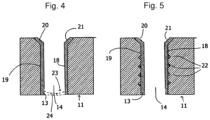
- the sleeve 18 (see Figs. 4 and 5 ) can have an extension 21 at its front end 20, which makes sliding towards the back 11 difficult or impossible.
- the sleeve 18 can have expansion elements and can be designed, for example, as an expansion dowel.
- the sleeves can have elevations 22 on their outer circumference (see Fig. 5 ) to enable or improve frictional engagement.
- the sleeve 18 comprises a sleeve base 23 (in Fig. 4 shown in dashed lines), the sleeve base 23 being arranged opposite the front end 20 of the sleeve 18.
- the sleeve base 23 has a sleeve base hole 24.
- the base of the sleeve can also remain completely free.
- the sleeve 18 can be (different from the Figures 3 to 5 ) also only extend over a certain section of the hole walls 19, for example only up to at least 80% of the extent of the hole walls 19 is measured from the first end 20 of the sleeve 18.
- the gypsum perforated panel 12 can have a fold on one or more of its sides, so that the building panels, for example, butt together and possibly no filling is required.
- the building board can be used in particular in a cassette deck arrangement.
- the sleeve can be coated on the inside, for example with a white paint, and preferably be flush with the surface of the perforated plasterboard 12, which can improve the overall visual impression and the brightness of the room.
- a special sleeve or a special fastening device can be provided for each hole pattern.
- different sleeves can be used on the same building board.
- the perforation can be in the form of a straight round perforation, a straight square perforation or an offset round perforation.
Landscapes
- Engineering & Computer Science (AREA)
- Architecture (AREA)
- Physics & Mathematics (AREA)
- Civil Engineering (AREA)
- Structural Engineering (AREA)
- Acoustics & Sound (AREA)
- Electromagnetism (AREA)
- Building Environments (AREA)
- Finishing Walls (AREA)
- Connection Of Plates (AREA)
- Panels For Use In Building Construction (AREA)
Priority Applications (1)
| Application Number | Priority Date | Filing Date | Title |
|---|---|---|---|
| PL10718944.1T PL2563984T3 (pl) | 2010-04-28 | 2010-04-28 | Płyta budowlana lub zestaw płyty budowlanej, system mocowania płyty budowlanej oraz sposób mocowania płyty budowlanej |
Applications Claiming Priority (1)
| Application Number | Priority Date | Filing Date | Title |
|---|---|---|---|
| PCT/EP2010/055721 WO2011134506A1 (de) | 2010-04-28 | 2010-04-28 | Bauplatte bzw. bauplattenset, befestigungssystem für eine bauplatte sowie verfahren zur befestigung einer bauplatte |
Publications (3)
| Publication Number | Publication Date |
|---|---|
| EP2563984A1 EP2563984A1 (de) | 2013-03-06 |
| EP2563984B1 true EP2563984B1 (de) | 2023-12-20 |
| EP2563984C0 EP2563984C0 (de) | 2023-12-20 |
Family
ID=43531144
Family Applications (1)
| Application Number | Title | Priority Date | Filing Date |
|---|---|---|---|
| EP10718944.1A Active EP2563984B1 (de) | 2010-04-28 | 2010-04-28 | Bauplatte bzw. bauplattenset, befestigungssystem für eine bauplatte sowie verfahren zur befestigung einer bauplatte |
Country Status (10)
| Country | Link |
|---|---|
| EP (1) | EP2563984B1 (pl) |
| JP (1) | JP5892936B2 (pl) |
| KR (2) | KR20170101321A (pl) |
| CN (1) | CN102472045B (pl) |
| AU (1) | AU2010352423B2 (pl) |
| BR (1) | BR112012027723A2 (pl) |
| ES (1) | ES2968887T3 (pl) |
| NZ (1) | NZ601992A (pl) |
| PL (1) | PL2563984T3 (pl) |
| WO (1) | WO2011134506A1 (pl) |
Families Citing this family (7)
| Publication number | Priority date | Publication date | Assignee | Title |
|---|---|---|---|---|
| FR2998907B1 (fr) * | 2012-12-04 | 2016-02-26 | Enia Arch | Structure modulaire de cloison pour la delimitation de poste de travail notamment |
| CN103526840A (zh) * | 2013-10-13 | 2014-01-22 | 许庆华 | 石灰环保吸音板 |
| CN103526845A (zh) * | 2013-10-13 | 2014-01-22 | 许庆华 | 麦饭石环保吸音板 |
| CN103556728A (zh) * | 2013-10-13 | 2014-02-05 | 许庆华 | 水淬矿渣环保吸音板 |
| CN103526846A (zh) * | 2013-10-13 | 2014-01-22 | 许庆华 | 滑石环保吸音板 |
| CN103526848A (zh) * | 2013-10-13 | 2014-01-22 | 许庆华 | 凹凸棒环保吸音板 |
| CH709367A2 (de) * | 2014-03-10 | 2015-09-15 | Akustik & Raum Ag | Verfahren zur Herstellung einer Verbund-Deckschicht für ein schallabsorbierendes Element und Verbund-Deckschicht. |
Citations (4)
| Publication number | Priority date | Publication date | Assignee | Title |
|---|---|---|---|---|
| DE1784050A1 (de) * | 1968-07-02 | 1971-07-08 | Artur Fischer | Duebel zur Abstandsbefestigung von Bauteilen |
| US4770583A (en) * | 1984-12-20 | 1988-09-13 | Stig Danielsson | Fastening means for fixing of a screw or the like in a hole preferably made in a plaster board |
| WO2006050665A1 (fr) * | 2004-11-09 | 2006-05-18 | Xuewen Wu | Moule de remplissage et sa structure sandwich et creuse |
| US20100003102A1 (en) * | 2005-12-14 | 2010-01-07 | Hitoshi Nagaiwa | Mechanical Blind Expansion Board-Anchor |
Family Cites Families (14)
| Publication number | Priority date | Publication date | Assignee | Title |
|---|---|---|---|---|
| US2071865A (en) * | 1932-12-22 | 1937-02-23 | Johns Manville | Building wall assembly |
| FR744204A (pl) * | 1933-04-05 | 1933-04-14 | ||
| US2706315A (en) * | 1949-06-11 | 1955-04-19 | Manley R Price | Wall or ceiling treatment |
| US2924856A (en) * | 1955-07-13 | 1960-02-16 | Sanymetal Products Company Inc | Perforated tile supporting system |
| US3020184A (en) * | 1955-09-30 | 1962-02-06 | Patent & Licensing Corp | Sound dampening composition |
| JPS366739Y1 (pl) * | 1955-12-23 | 1961-04-07 | ||
| DE2947607C2 (de) * | 1979-11-26 | 1985-01-24 | Fa. Carl Freudenberg, 6940 Weinheim | Luftschallschluckende Verkleidung für eine Wand oder Decke |
| JPH08189104A (ja) * | 1995-01-12 | 1996-07-23 | Bridgestone Corp | 吸音体の取付装置 |
| JP4171239B2 (ja) * | 2001-12-14 | 2008-10-22 | 若井産業株式会社 | ねじ付きアンカー |
| CN100472016C (zh) * | 2004-04-28 | 2009-03-25 | 吉野石膏株式会社 | 板式建材、板式建材的制造方法以及板式建材的施工方法 |
| JP4763276B2 (ja) * | 2004-04-28 | 2011-08-31 | 吉野石膏株式会社 | ボード建材、ボード建材製造方法及びボード建材施工方法 |
| CN2866075Y (zh) * | 2005-11-03 | 2007-02-07 | 白雪原 | 轻质墙板模具组合装置 |
| DE102007040034B4 (de) * | 2007-08-24 | 2010-02-11 | Vogl, Erich R. | Gipskartonlochplatte zur Schallabsorption |
| CN101550739B (zh) * | 2009-05-12 | 2011-11-09 | 四川善晟建筑智能化工程有限公司 | 用于建造平面结构的组合建筑模块及制作方法 |
-
2010
- 2010-04-28 KR KR1020177023835A patent/KR20170101321A/ko not_active Ceased
- 2010-04-28 PL PL10718944.1T patent/PL2563984T3/pl unknown
- 2010-04-28 AU AU2010352423A patent/AU2010352423B2/en active Active
- 2010-04-28 CN CN201080027132.3A patent/CN102472045B/zh not_active Expired - Fee Related
- 2010-04-28 NZ NZ601992A patent/NZ601992A/en unknown
- 2010-04-28 JP JP2012530182A patent/JP5892936B2/ja active Active
- 2010-04-28 ES ES10718944T patent/ES2968887T3/es active Active
- 2010-04-28 WO PCT/EP2010/055721 patent/WO2011134506A1/de not_active Ceased
- 2010-04-28 KR KR1020127029970A patent/KR20130063500A/ko not_active Ceased
- 2010-04-28 BR BR112012027723A patent/BR112012027723A2/pt not_active IP Right Cessation
- 2010-04-28 EP EP10718944.1A patent/EP2563984B1/de active Active
Patent Citations (4)
| Publication number | Priority date | Publication date | Assignee | Title |
|---|---|---|---|---|
| DE1784050A1 (de) * | 1968-07-02 | 1971-07-08 | Artur Fischer | Duebel zur Abstandsbefestigung von Bauteilen |
| US4770583A (en) * | 1984-12-20 | 1988-09-13 | Stig Danielsson | Fastening means for fixing of a screw or the like in a hole preferably made in a plaster board |
| WO2006050665A1 (fr) * | 2004-11-09 | 2006-05-18 | Xuewen Wu | Moule de remplissage et sa structure sandwich et creuse |
| US20100003102A1 (en) * | 2005-12-14 | 2010-01-07 | Hitoshi Nagaiwa | Mechanical Blind Expansion Board-Anchor |
Also Published As
| Publication number | Publication date |
|---|---|
| KR20130063500A (ko) | 2013-06-14 |
| JP2013505382A (ja) | 2013-02-14 |
| KR20170101321A (ko) | 2017-09-05 |
| EP2563984A1 (de) | 2013-03-06 |
| AU2010352423B2 (en) | 2015-09-03 |
| PL2563984T3 (pl) | 2024-03-25 |
| WO2011134506A1 (de) | 2011-11-03 |
| AU2010352423A1 (en) | 2012-10-04 |
| ES2968887T3 (es) | 2024-05-14 |
| EP2563984C0 (de) | 2023-12-20 |
| CN102472045A (zh) | 2012-05-23 |
| JP5892936B2 (ja) | 2016-03-23 |
| BR112012027723A2 (pt) | 2016-09-06 |
| CN102472045B (zh) | 2015-03-25 |
| NZ601992A (en) | 2014-08-29 |
Similar Documents
| Publication | Publication Date | Title |
|---|---|---|
| EP3256660B1 (de) | Fugendichtungselement und dichtanordnung mit derartigem fugendichtungselement | |
| EP1857607B1 (de) | Befestigungelement und Verfahren zur Befestigung von Dämmstoffplatten | |
| EP2042666B1 (de) | Befestigungselement und Verfahren zur vertieften Montage einer Dämmstoffplatte | |
| WO2011134506A1 (de) | Bauplatte bzw. bauplattenset, befestigungssystem für eine bauplatte sowie verfahren zur befestigung einer bauplatte | |
| DE202010004924U1 (de) | Vorrichtung zum Positionieren eines Bauelements während der Montage des Bauelements an einem Bauwerk | |
| EP2844808B1 (de) | Verfahren zur herstellung einer trockenbauwand | |
| EP2044270B1 (de) | Befestigungssysteme und verfahren zur montage von dämmstoffplatten | |
| DE102004064114B4 (de) | Befestigungselement für Dämmstoffplatten | |
| EP2591181B1 (de) | Lochplatten auf Basis von Gips sowie Verfahren zum Verlegen derselben | |
| EP1870529B1 (de) | Wand/Schrankanordnung mit einer Rahmenkonstruktion | |
| DE102012221746B4 (de) | Wandheizelement | |
| EP3214321B1 (de) | Anordnung mit einer leichtbauplatte und einem dübel sowie verfahren zum einsetzen eines dübels in eine leichtbauplatte | |
| DE3333055C2 (de) | Vorrichtung zum Befestigen von Latten | |
| EP3138974A1 (de) | Verfahren zur anbringung von dämmstoffplatten oder dergleichen dämmmittel an einen tragenden untergrund sowie ein befestigungssystem dafür | |
| DE202009012420U1 (de) | Montagesystem für Isolierstoffplatten | |
| DE202017105573U1 (de) | Einbaukasten sowie eine entsprechende Montageanordnung und ein entsprechender Bausatz | |
| EP2740947B1 (de) | Befestigungssystem mit entkoppelbarem Halteteller | |
| DE102011012023A1 (de) | Verbindungselement zur Verbindung von flächigen Bauteilen | |
| DE102015015604A1 (de) | Aufnahmeelement für eine Beschattungseinrichtung und Verfahren zum Befestigen eines solchen an der Außenseite eines Gebäudes | |
| EP2924187B1 (de) | Profilschiene sowie zugehöriges Verkleidungselement zur Verkleidung einer Laibung | |
| AT525083B1 (de) | Bausatz für einen Attikaaufbau an einem Gebäude | |
| EP2562320B1 (de) | Verfahren zur Ausbildung eines Fassadensystems sowie Fassadensystem | |
| DE102010026602A1 (de) | Lochplatten auf Basis von Gips sowie Verfahren zum Verlegen derselben | |
| DE102019105126A9 (de) | Universelles Montageset zum Montieren eines Rahmens an einem Untergrund | |
| DE10000171B4 (de) | Dämpfungselement mit Verbindungselementen zur akustisch entkoppelten Verbindungmit Bauteilen |
Legal Events
| Date | Code | Title | Description |
|---|---|---|---|
| PUAI | Public reference made under article 153(3) epc to a published international application that has entered the european phase |
Free format text: ORIGINAL CODE: 0009012 |
|
| 17P | Request for examination filed |
Effective date: 20120516 |
|
| AK | Designated contracting states |
Kind code of ref document: A1 Designated state(s): AT BE BG CH CY CZ DE DK EE ES FI FR GB GR HR HU IE IS IT LI LT LU LV MC MK MT NL NO PL PT RO SE SI SK SM TR |
|
| RIN1 | Information on inventor provided before grant (corrected) |
Inventor name: FLENNERT, BRUNO Inventor name: RUEMLER, WOLFGANG Inventor name: WANDLER, KLAUS Inventor name: MITTNACHT, SEBASTIAN |
|
| DAX | Request for extension of the european patent (deleted) | ||
| REG | Reference to a national code |
Ref country code: HK Ref legal event code: DE Ref document number: 1177956 Country of ref document: HK |
|
| STAA | Information on the status of an ep patent application or granted ep patent |
Free format text: STATUS: EXAMINATION IS IN PROGRESS |
|
| 17Q | First examination report despatched |
Effective date: 20170117 |
|
| REG | Reference to a national code |
Ref country code: HK Ref legal event code: WD Ref document number: 1177956 Country of ref document: HK |
|
| GRAP | Despatch of communication of intention to grant a patent |
Free format text: ORIGINAL CODE: EPIDOSNIGR1 |
|
| STAA | Information on the status of an ep patent application or granted ep patent |
Free format text: STATUS: GRANT OF PATENT IS INTENDED |
|
| INTG | Intention to grant announced |
Effective date: 20230119 |
|
| GRAJ | Information related to disapproval of communication of intention to grant by the applicant or resumption of examination proceedings by the epo deleted |
Free format text: ORIGINAL CODE: EPIDOSDIGR1 |
|
| STAA | Information on the status of an ep patent application or granted ep patent |
Free format text: STATUS: EXAMINATION IS IN PROGRESS |
|
| INTC | Intention to grant announced (deleted) | ||
| GRAP | Despatch of communication of intention to grant a patent |
Free format text: ORIGINAL CODE: EPIDOSNIGR1 |
|
| STAA | Information on the status of an ep patent application or granted ep patent |
Free format text: STATUS: GRANT OF PATENT IS INTENDED |
|
| INTG | Intention to grant announced |
Effective date: 20230711 |
|
| GRAS | Grant fee paid |
Free format text: ORIGINAL CODE: EPIDOSNIGR3 |
|
| GRAA | (expected) grant |
Free format text: ORIGINAL CODE: 0009210 |
|
| STAA | Information on the status of an ep patent application or granted ep patent |
Free format text: STATUS: THE PATENT HAS BEEN GRANTED |
|
| AK | Designated contracting states |
Kind code of ref document: B1 Designated state(s): AT BE BG CH CY CZ DE DK EE ES FI FR GB GR HR HU IE IS IT LI LT LU LV MC MK MT NL NO PL PT RO SE SI SK SM TR |
|
| REG | Reference to a national code |
Ref country code: GB Ref legal event code: FG4D Free format text: NOT ENGLISH |
|
| REG | Reference to a national code |
Ref country code: DE Ref legal event code: R096 Ref document number: 502010017078 Country of ref document: DE |
|
| REG | Reference to a national code |
Ref country code: CH Ref legal event code: EP |
|
| REG | Reference to a national code |
Ref country code: IE Ref legal event code: FG4D Free format text: LANGUAGE OF EP DOCUMENT: GERMAN |
|
| U01 | Request for unitary effect filed |
Effective date: 20240108 |
|
| U07 | Unitary effect registered |
Designated state(s): AT BE BG DE DK EE FI FR IT LT LU LV MT NL PT SE SI Effective date: 20240117 |
|
| PG25 | Lapsed in a contracting state [announced via postgrant information from national office to epo] |
Ref country code: GR Free format text: LAPSE BECAUSE OF FAILURE TO SUBMIT A TRANSLATION OF THE DESCRIPTION OR TO PAY THE FEE WITHIN THE PRESCRIBED TIME-LIMIT Effective date: 20240321 |
|
| PG25 | Lapsed in a contracting state [announced via postgrant information from national office to epo] |
Ref country code: GR Free format text: LAPSE BECAUSE OF FAILURE TO SUBMIT A TRANSLATION OF THE DESCRIPTION OR TO PAY THE FEE WITHIN THE PRESCRIBED TIME-LIMIT Effective date: 20240321 |
|
| REG | Reference to a national code |
Ref country code: ES Ref legal event code: FG2A Ref document number: 2968887 Country of ref document: ES Kind code of ref document: T3 Effective date: 20240514 |
|
| PG25 | Lapsed in a contracting state [announced via postgrant information from national office to epo] |
Ref country code: NO Free format text: LAPSE BECAUSE OF FAILURE TO SUBMIT A TRANSLATION OF THE DESCRIPTION OR TO PAY THE FEE WITHIN THE PRESCRIBED TIME-LIMIT Effective date: 20240320 Ref country code: HR Free format text: LAPSE BECAUSE OF FAILURE TO SUBMIT A TRANSLATION OF THE DESCRIPTION OR TO PAY THE FEE WITHIN THE PRESCRIBED TIME-LIMIT Effective date: 20231220 |
|
| U20 | Renewal fee for the european patent with unitary effect paid |
Year of fee payment: 15 Effective date: 20240429 |
|
| PG25 | Lapsed in a contracting state [announced via postgrant information from national office to epo] |
Ref country code: IS Free format text: LAPSE BECAUSE OF FAILURE TO SUBMIT A TRANSLATION OF THE DESCRIPTION OR TO PAY THE FEE WITHIN THE PRESCRIBED TIME-LIMIT Effective date: 20240420 |
|
| PG25 | Lapsed in a contracting state [announced via postgrant information from national office to epo] |
Ref country code: CZ Free format text: LAPSE BECAUSE OF FAILURE TO SUBMIT A TRANSLATION OF THE DESCRIPTION OR TO PAY THE FEE WITHIN THE PRESCRIBED TIME-LIMIT Effective date: 20231220 |
|
| PG25 | Lapsed in a contracting state [announced via postgrant information from national office to epo] |
Ref country code: SK Free format text: LAPSE BECAUSE OF FAILURE TO SUBMIT A TRANSLATION OF THE DESCRIPTION OR TO PAY THE FEE WITHIN THE PRESCRIBED TIME-LIMIT Effective date: 20231220 |
|
| PG25 | Lapsed in a contracting state [announced via postgrant information from national office to epo] |
Ref country code: SM Free format text: LAPSE BECAUSE OF FAILURE TO SUBMIT A TRANSLATION OF THE DESCRIPTION OR TO PAY THE FEE WITHIN THE PRESCRIBED TIME-LIMIT Effective date: 20231220 Ref country code: SK Free format text: LAPSE BECAUSE OF FAILURE TO SUBMIT A TRANSLATION OF THE DESCRIPTION OR TO PAY THE FEE WITHIN THE PRESCRIBED TIME-LIMIT Effective date: 20231220 Ref country code: RO Free format text: LAPSE BECAUSE OF FAILURE TO SUBMIT A TRANSLATION OF THE DESCRIPTION OR TO PAY THE FEE WITHIN THE PRESCRIBED TIME-LIMIT Effective date: 20231220 Ref country code: IS Free format text: LAPSE BECAUSE OF FAILURE TO SUBMIT A TRANSLATION OF THE DESCRIPTION OR TO PAY THE FEE WITHIN THE PRESCRIBED TIME-LIMIT Effective date: 20240420 Ref country code: CZ Free format text: LAPSE BECAUSE OF FAILURE TO SUBMIT A TRANSLATION OF THE DESCRIPTION OR TO PAY THE FEE WITHIN THE PRESCRIBED TIME-LIMIT Effective date: 20231220 |
|
| REG | Reference to a national code |
Ref country code: DE Ref legal event code: R097 Ref document number: 502010017078 Country of ref document: DE |
|
| PLBE | No opposition filed within time limit |
Free format text: ORIGINAL CODE: 0009261 |
|
| STAA | Information on the status of an ep patent application or granted ep patent |
Free format text: STATUS: NO OPPOSITION FILED WITHIN TIME LIMIT |
|
| PG25 | Lapsed in a contracting state [announced via postgrant information from national office to epo] |
Ref country code: MC Free format text: LAPSE BECAUSE OF FAILURE TO SUBMIT A TRANSLATION OF THE DESCRIPTION OR TO PAY THE FEE WITHIN THE PRESCRIBED TIME-LIMIT Effective date: 20231220 |
|
| 26N | No opposition filed |
Effective date: 20240923 |
|
| PG25 | Lapsed in a contracting state [announced via postgrant information from national office to epo] |
Ref country code: MC Free format text: LAPSE BECAUSE OF FAILURE TO SUBMIT A TRANSLATION OF THE DESCRIPTION OR TO PAY THE FEE WITHIN THE PRESCRIBED TIME-LIMIT Effective date: 20231220 |
|
| GBPC | Gb: european patent ceased through non-payment of renewal fee |
Effective date: 20240428 |
|
| PG25 | Lapsed in a contracting state [announced via postgrant information from national office to epo] |
Ref country code: GB Free format text: LAPSE BECAUSE OF NON-PAYMENT OF DUE FEES Effective date: 20240428 |
|
| PG25 | Lapsed in a contracting state [announced via postgrant information from national office to epo] |
Ref country code: GB Free format text: LAPSE BECAUSE OF NON-PAYMENT OF DUE FEES Effective date: 20240428 |
|
| PG25 | Lapsed in a contracting state [announced via postgrant information from national office to epo] |
Ref country code: IE Free format text: LAPSE BECAUSE OF NON-PAYMENT OF DUE FEES Effective date: 20240428 |
|
| U20 | Renewal fee for the european patent with unitary effect paid |
Year of fee payment: 16 Effective date: 20250428 |
|
| PGFP | Annual fee paid to national office [announced via postgrant information from national office to epo] |
Ref country code: ES Payment date: 20250505 Year of fee payment: 16 |
|
| PGFP | Annual fee paid to national office [announced via postgrant information from national office to epo] |
Ref country code: CH Payment date: 20250501 Year of fee payment: 16 |
|
| PG25 | Lapsed in a contracting state [announced via postgrant information from national office to epo] |
Ref country code: CY Free format text: LAPSE BECAUSE OF FAILURE TO SUBMIT A TRANSLATION OF THE DESCRIPTION OR TO PAY THE FEE WITHIN THE PRESCRIBED TIME-LIMIT; INVALID AB INITIO Effective date: 20100428 |
|
| PG25 | Lapsed in a contracting state [announced via postgrant information from national office to epo] |
Ref country code: HU Free format text: LAPSE BECAUSE OF FAILURE TO SUBMIT A TRANSLATION OF THE DESCRIPTION OR TO PAY THE FEE WITHIN THE PRESCRIBED TIME-LIMIT; INVALID AB INITIO Effective date: 20100428 |
|
| PGFP | Annual fee paid to national office [announced via postgrant information from national office to epo] |
Ref country code: PL Payment date: 20250405 Year of fee payment: 16 |
|
| REG | Reference to a national code |
Ref country code: CH Ref legal event code: U11 Free format text: ST27 STATUS EVENT CODE: U-0-0-U10-U11 (AS PROVIDED BY THE NATIONAL OFFICE) Effective date: 20260501 |