EP2562899A2 - Direct current bus management controller - Google Patents
Direct current bus management controller Download PDFInfo
- Publication number
- EP2562899A2 EP2562899A2 EP20120181417 EP12181417A EP2562899A2 EP 2562899 A2 EP2562899 A2 EP 2562899A2 EP 20120181417 EP20120181417 EP 20120181417 EP 12181417 A EP12181417 A EP 12181417A EP 2562899 A2 EP2562899 A2 EP 2562899A2
- Authority
- EP
- European Patent Office
- Prior art keywords
- bus
- power
- management section
- voltage
- coupled
- Prior art date
- Legal status (The legal status is an assumption and is not a legal conclusion. Google has not performed a legal analysis and makes no representation as to the accuracy of the status listed.)
- Granted
Links
- 238000007726 management method Methods 0.000 claims description 141
- 238000000034 method Methods 0.000 claims description 23
- 238000004146 energy storage Methods 0.000 claims description 22
- 230000004044 response Effects 0.000 claims description 12
- 238000001816 cooling Methods 0.000 claims description 7
- 238000010248 power generation Methods 0.000 claims description 3
- 238000004891 communication Methods 0.000 claims 1
- 238000010586 diagram Methods 0.000 description 12
- 230000001172 regenerating effect Effects 0.000 description 12
- 230000006870 function Effects 0.000 description 9
- 230000002457 bidirectional effect Effects 0.000 description 4
- 238000004590 computer program Methods 0.000 description 4
- 230000009993 protective function Effects 0.000 description 4
- 230000008569 process Effects 0.000 description 3
- 230000004075 alteration Effects 0.000 description 1
- 230000015556 catabolic process Effects 0.000 description 1
- 230000008859 change Effects 0.000 description 1
- 238000002485 combustion reaction Methods 0.000 description 1
- 238000007796 conventional method Methods 0.000 description 1
- 238000013016 damping Methods 0.000 description 1
- 238000006731 degradation reaction Methods 0.000 description 1
- 238000001514 detection method Methods 0.000 description 1
- 230000000694 effects Effects 0.000 description 1
- 238000003306 harvesting Methods 0.000 description 1
- 230000006872 improvement Effects 0.000 description 1
- 238000002955 isolation Methods 0.000 description 1
- 230000010355 oscillation Effects 0.000 description 1
- 238000004806 packaging method and process Methods 0.000 description 1
- 230000021715 photosynthesis, light harvesting Effects 0.000 description 1
- 239000004065 semiconductor Substances 0.000 description 1
- 239000007787 solid Substances 0.000 description 1
- 230000006641 stabilisation Effects 0.000 description 1
- 238000011105 stabilization Methods 0.000 description 1
- 238000006467 substitution reaction Methods 0.000 description 1
Images


Classifications
-
- B—PERFORMING OPERATIONS; TRANSPORTING
- B60—VEHICLES IN GENERAL
- B60R—VEHICLES, VEHICLE FITTINGS, OR VEHICLE PARTS, NOT OTHERWISE PROVIDED FOR
- B60R16/00—Electric or fluid circuits specially adapted for vehicles and not otherwise provided for; Arrangement of elements of electric or fluid circuits specially adapted for vehicles and not otherwise provided for
- B60R16/02—Electric or fluid circuits specially adapted for vehicles and not otherwise provided for; Arrangement of elements of electric or fluid circuits specially adapted for vehicles and not otherwise provided for electric constitutive elements
- B60R16/03—Electric or fluid circuits specially adapted for vehicles and not otherwise provided for; Arrangement of elements of electric or fluid circuits specially adapted for vehicles and not otherwise provided for electric constitutive elements for supply of electrical power to vehicle subsystems or for
-
- B—PERFORMING OPERATIONS; TRANSPORTING
- B60—VEHICLES IN GENERAL
- B60L—PROPULSION OF ELECTRICALLY-PROPELLED VEHICLES; SUPPLYING ELECTRIC POWER FOR AUXILIARY EQUIPMENT OF ELECTRICALLY-PROPELLED VEHICLES; ELECTRODYNAMIC BRAKE SYSTEMS FOR VEHICLES IN GENERAL; MAGNETIC SUSPENSION OR LEVITATION FOR VEHICLES; MONITORING OPERATING VARIABLES OF ELECTRICALLY-PROPELLED VEHICLES; ELECTRIC SAFETY DEVICES FOR ELECTRICALLY-PROPELLED VEHICLES
- B60L50/00—Electric propulsion with power supplied within the vehicle
- B60L50/10—Electric propulsion with power supplied within the vehicle using propulsion power supplied by engine-driven generators, e.g. generators driven by combustion engines
- B60L50/15—Electric propulsion with power supplied within the vehicle using propulsion power supplied by engine-driven generators, e.g. generators driven by combustion engines with additional electric power supply
-
- B—PERFORMING OPERATIONS; TRANSPORTING
- B60—VEHICLES IN GENERAL
- B60L—PROPULSION OF ELECTRICALLY-PROPELLED VEHICLES; SUPPLYING ELECTRIC POWER FOR AUXILIARY EQUIPMENT OF ELECTRICALLY-PROPELLED VEHICLES; ELECTRODYNAMIC BRAKE SYSTEMS FOR VEHICLES IN GENERAL; MAGNETIC SUSPENSION OR LEVITATION FOR VEHICLES; MONITORING OPERATING VARIABLES OF ELECTRICALLY-PROPELLED VEHICLES; ELECTRIC SAFETY DEVICES FOR ELECTRICALLY-PROPELLED VEHICLES
- B60L7/00—Electrodynamic brake systems for vehicles in general
- B60L7/22—Dynamic electric resistor braking, combined with dynamic electric regenerative braking
-
- H—ELECTRICITY
- H02—GENERATION; CONVERSION OR DISTRIBUTION OF ELECTRIC POWER
- H02J—CIRCUIT ARRANGEMENTS OR SYSTEMS FOR SUPPLYING OR DISTRIBUTING ELECTRIC POWER; SYSTEMS FOR STORING ELECTRIC ENERGY
- H02J1/00—Circuit arrangements for dc mains or dc distribution networks
- H02J1/10—Parallel operation of dc sources
-
- H—ELECTRICITY
- H02—GENERATION; CONVERSION OR DISTRIBUTION OF ELECTRIC POWER
- H02J—CIRCUIT ARRANGEMENTS OR SYSTEMS FOR SUPPLYING OR DISTRIBUTING ELECTRIC POWER; SYSTEMS FOR STORING ELECTRIC ENERGY
- H02J1/00—Circuit arrangements for dc mains or dc distribution networks
- H02J1/14—Balancing the load in a network
-
- H—ELECTRICITY
- H02—GENERATION; CONVERSION OR DISTRIBUTION OF ELECTRIC POWER
- H02J—CIRCUIT ARRANGEMENTS OR SYSTEMS FOR SUPPLYING OR DISTRIBUTING ELECTRIC POWER; SYSTEMS FOR STORING ELECTRIC ENERGY
- H02J2310/00—The network for supplying or distributing electric power characterised by its spatial reach or by the load
- H02J2310/40—The network being an on-board power network, i.e. within a vehicle
-
- Y—GENERAL TAGGING OF NEW TECHNOLOGICAL DEVELOPMENTS; GENERAL TAGGING OF CROSS-SECTIONAL TECHNOLOGIES SPANNING OVER SEVERAL SECTIONS OF THE IPC; TECHNICAL SUBJECTS COVERED BY FORMER USPC CROSS-REFERENCE ART COLLECTIONS [XRACs] AND DIGESTS
- Y02—TECHNOLOGIES OR APPLICATIONS FOR MITIGATION OR ADAPTATION AGAINST CLIMATE CHANGE
- Y02T—CLIMATE CHANGE MITIGATION TECHNOLOGIES RELATED TO TRANSPORTATION
- Y02T10/00—Road transport of goods or passengers
- Y02T10/60—Other road transportation technologies with climate change mitigation effect
- Y02T10/70—Energy storage systems for electromobility, e.g. batteries
-
- Y—GENERAL TAGGING OF NEW TECHNOLOGICAL DEVELOPMENTS; GENERAL TAGGING OF CROSS-SECTIONAL TECHNOLOGIES SPANNING OVER SEVERAL SECTIONS OF THE IPC; TECHNICAL SUBJECTS COVERED BY FORMER USPC CROSS-REFERENCE ART COLLECTIONS [XRACs] AND DIGESTS
- Y02—TECHNOLOGIES OR APPLICATIONS FOR MITIGATION OR ADAPTATION AGAINST CLIMATE CHANGE
- Y02T—CLIMATE CHANGE MITIGATION TECHNOLOGIES RELATED TO TRANSPORTATION
- Y02T10/00—Road transport of goods or passengers
- Y02T10/60—Other road transportation technologies with climate change mitigation effect
- Y02T10/7072—Electromobility specific charging systems or methods for batteries, ultracapacitors, supercapacitors or double-layer capacitors
-
- Y—GENERAL TAGGING OF NEW TECHNOLOGICAL DEVELOPMENTS; GENERAL TAGGING OF CROSS-SECTIONAL TECHNOLOGIES SPANNING OVER SEVERAL SECTIONS OF THE IPC; TECHNICAL SUBJECTS COVERED BY FORMER USPC CROSS-REFERENCE ART COLLECTIONS [XRACs] AND DIGESTS
- Y02—TECHNOLOGIES OR APPLICATIONS FOR MITIGATION OR ADAPTATION AGAINST CLIMATE CHANGE
- Y02T—CLIMATE CHANGE MITIGATION TECHNOLOGIES RELATED TO TRANSPORTATION
- Y02T10/00—Road transport of goods or passengers
- Y02T10/80—Technologies aiming to reduce greenhouse gasses emissions common to all road transportation technologies
- Y02T10/92—Energy efficient charging or discharging systems for batteries, ultracapacitors, supercapacitors or double-layer capacitors specially adapted for vehicles
Abstract
Description
- The subject matter disclosed herein relates to electric power generation and distribution, and more particularly to a direct current (DC) bus management controller and method for controlling a DC bus.
- Electrical power systems in hybrid vehicles, such as military hybrid vehicles, can include high voltage direct current (DC) power generation and distribution in systems having multiple loads and power sources. Some of the loads are regenerative loads, such as electrically driven actuators. Regenerative power from these loads may be returned to the distribution (system) bus. Conventional methods utilize shunt regulators to direct the regenerative power into power dissipation resistors, These methods require additional thermal management to reject generated heat losses, and typically do not allow for the capture and re-use of regenerative energy,
- Exemplary embodiments include a direct current bus management system, including a power management and distribution unit, having a source management section, a bus management section coupled to the source section, a load management section coupled to the bus management section, a DC bus couple to the power management and distribution unit, a plurality of DC sources couple to the source management section and a plurality of loads coupled to the load management section, wherein the bus management section is configured to reconfigure excess DC power on the DC bus from the DC inputs from the plurality of DC sources based on a plurality of priorities, a plurality of feedback signals and a plurality of system parameters.
- Additional exemplary embodiments can include a power management and distribution apparatus, including a source management section, a bus management section coupled to the source management section, a load management section coupled to the bus management section, and a DC bus coupled to the source management section, the bus management section, and the load management section, wherein the bus management section is configured to reconfigure excess DC power on the DC bus based on a plurality of priorities, a plurality of feedback signals and a plurality of system parameters.
- Further exemplary embodiments include DC bus management method in a DC bus, the method including comparing a DC bus voltage against a plurality of voltage references, in response to an excess of the DC voltage compared to a first voltage reference of the plurality of voltage references, sending a first control signal instructing a first redirection of DC power in the DC bus, in response to an excess of the DC voltage compared to a second voltage reference of the plurality of voltage references, sending a second control signal instructing a second redirection of DC power in the DC bus and in response to an excess of the DC voltage compared to a third voltage reference of the plurality of voltage references, sending a third control signal instructing a third redirection of DC power in the DC bus.
- The subject matter which is regarded as the invention is particularly pointed out and distinctly claimed in the claims at the conclusion of the specification. The foregoing and other features, and advantages of the invention are apparent from the following detailed description taken in conjunction with the accompanying drawings in which:
-
FIG. 1 illustrates a system diagram of a DC bus management system; -
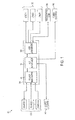
FIG. 2 illustrates a system diagram of the DC bus management system ofFIG. 1 in further detail; -
FIG. 3 illustrates the DC bus management controller ofFIG. 2 ; and -
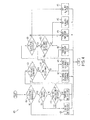
FIG. 4 is a flow chart that illustrates a DC management method in accordance with an embodiment. - Embodiments include systems and methods for enabling DC bus system reconfiguration to redirect DC power in a high voltage DC system. The systems and methods described herein harvest regenerative energy by redirecting DC power to the energy storage device or converting the DC power to mechanical energy if the DC power cannot be stored, and thus maintain good power quality on the DC bus without the addition of large DC filters, during load transients.
-
FIG. 1 illustrates a system diagram of a DCbus management system 100. Thesystem 100 includes a power management and distribution (PMAD)unit 105, which includes asource management section 110 coupled to abus management section 115, which is coupled to aload management section 120.FIG. 1 thus illustrates the interrelation between functions of each of thesource management section 110,bus management section 115, and theload management section 120. Thesystem 100 further includes multiple high voltage DC sources 125 (i.e.,source source management section 110, andmultiple loads 130 coupled to theload management section 120. Thesystem 100 further includes aregenerative load 135 from which regenerative energy can be recovered as further described herein. Anenergy storage unit 140 and apower dissipater 145 can further be coupled to thebus management section 115. In one embodiment, theenergy storage unit 140 stores redirected DC energy, and thepower dissipater 145 dissipates any unrecovered energy. Thepower dissipater 145 can be a power resistor. Thepower dissipater 145 can also include a temperature sensor to monitor the temperature. - The
source management section 110, thebus management section 115 and theload management section 120 include various functions as described herein. In one embodiment, thesource management section 110 provides source protective functions including but not limited to: over/under voltage; over-temperature; excessive voltage ripple; and differential protection. In one embodiment, thebus management section 115 provides autonomous reconfiguration and redirection of DC power based on priorities, feedback signals and system parameters for increased efficiency and performance of thesystem 100. In one embodiment, theload management section 120 provides load protective functions including but not limited to: over-current; thermal memory; over/under voltage; over-temperature; excessive current ripple; and arc fault detection. Theload management section 120 further provides: load stabilization by actively damping load voltage oscillations; current limiting; soft start of capacitive loads; and nuisance trip avoidance. - As described above, the
bus management section 115 provides autonomous reconfiguration and redirection of DC power for increased efficiency and performance of thesystem 100. In one embodiment, thebus management section 115 executes a DC bus management process for providing the autonomous reconfiguration and redirection based on priorities, feedback signals and system parameters, The DC bus management process is described further herein and the following description discusses several of the supporting functions. -
FIG. 2 illustrates a system diagram of the DCbus management system 100 ofFIG. 1 in further detail. As described above, thesystem 100 includes thesource management section 110, thebus management section 115 and theload management section 120 In one embodiment, one or all of thesource management section 110, thebus management section 115 and theload management section 120 include at least one solid state power controller (SSPC), which are implemented in power distribution systems to replace traditional electromechanical circuit breakers. The functions of the SSPC can include power distribution and protection of power to different loads to name a few, In comparison to electromechanical devices, an SSPC provides fast response time, and eliminates arcing during tum-off transients and bouncin during turn-on transients. SSPCs typically do not suffer severe degradation during repeated fault isolation as compared with electromechanical devices. SSPCs facilitate advanced protection and diagnostics, and provide more efficient power distribution architectures and packaging techniques, due to the smaller size and weight than compared to conventional electromechanical switches. As such, the SSPCs allow thesource management section 110, thebus management section 115 and theload management section 120 to perform the protective functions described herein. The SSPCs can be classified as unidirectional and bidirectional. Both type of SSPCs conduct current in both directions. A unidirectional SSPC can interrupt current only in one direction from source to load and this are implemented in load management. Bidirectional SSPC can interrupt current in both directions that enables source and bus management. - Referring still to
FIG. 2 , thesource management section 110 induces a bidirectional SSPC 111 coupled to aDC bus 200. The SSPC 111 is further coupled to one ormore DC sources 125, one of which is illustrated inFIG. 2 . It can be appreciated that thesource management section 110 can include an additional SSPC for each additional source. As an illustrative example, theDC source 125 includes a prime mover (e.g., an internal combustion engine) 126, apermanent magnet generator 127 that generates an AC voltage an anactive rectifier 128 that converts the AC voltage to a DC voltage, and is coupled to the SSPC 111. Thebus management section 115 is also coupled to theDC bus 200. In one embodiment, thebus management section 115 includes a first bidirectional SSPC 116 coupled to theDC bus 200. The first SSPC 116 is also coupled to theenergy storage unit 140. As illustrated, theenergy storage unit 140 further includes abattery 141 coupled to a DC-DC converter 142, which converts DC to different levels of DC. Thebus management section 115 includes a second SSPC 117 that is coupled to theDC bus 200. The second SSPC 117 is also coupled to thepower dissipater 145. In one embodiment, thebus management section 115 further includes a DCbus management controller 118. In one embodiment, the DCbus management controller 118 is coupled to the first and second SSPC 116, 117, to theDC sources 125 and to afan load 150, which includes amotor drive 151 andfan 152. In one embodiment, the DCbus management controller 118 redirects the unused DC power to thefan load 150 for cooling purposes if the DCbus management controller 118 cannot redirect the DC power to one of the other reusable sources (e.g., the energy storage unit 140). As such, thesystem 100 can redirect DC power to thefan load 150 to cool thesystem 100. As further described herein, the DCbus management controller 118 sends and receives signals to instruct thesystem 100 how to redirect the DC power. As such, the DCbus management controller 118 coordinates bus connection and time duration to energy storage, energy dissipation (i.e., to the cooling fan), power dissipation to resistive loads, and DC sources. - The
load management section 120 is also coupled to theDC bus 200. Theload management section 120 includes a first SSPC 121 coupled to theDC bus 200 and to thefan load 150. Theload management section 120 further includes a second SSPC 122 coupled to theDC bus 200 and to theregenerative load 135. Theload management section 120 includes athird SSPC 123 coupled to theDC bus 200 and to thenon-regenerative load 130. The first, second andthird SSPCs fan load 150, theregenerative load 135 and thenon-regenerative load 130 as described herein. -
FIG. 3 illustrates the DCbus management controller 118 ofFIG. 2 . As described herein, the DCbus management controller 118 receives various feedback signals 305,parameters 310 andpriorities 315 to determine how to redirect DC power. In one embodiment, the feedback signals 305 include but are not limited to: DC bus voltage; battery voltage; cooling fan speed; and temperature of a power dissipating resistor, The DCbus management controller 118 can monitor the battery charge to determine if theenergy storage unit 140 is available to receive energy for storage. The DCbus management controller 118 can monitor thefan 152 speed to see if it is available to speed up in the event of extra DC power. The DCbus management controller 118 can monitor the temperature of thepower dissipater 145 to see if it has a temperature suitable to receive extra DC power. - In one embodiment, the
parameters 310 include but are not limited to: DC bus voltage; maximum battery charge rate; maximum fan speed; maximum power dissipation resistor temperature; and maximum generator negative torque. The maximum battery charge rate determines how fast thebattery 141 can charge in the event DC energy is directed to thebattery 141. The maximum fan speed determines the speed limit if DC power is diverted to it. The maximum power dissipation resistor temperature determines the upper limit of how high the temperature of thepower dissipater 145 can be if DC power is redirected to it. The maximum generator negative torque determines how much reverse torque can be applied in one of the DC loads 125. - In one embodiment, the
priorities 315 include, but are not limited to: DC bus power quality; energy storage; load increase (e.g., fan load 150); power dissipation resistor; and generator torque reversal. As such, priorities can be set to determine how extra DC power is redirected. - The DC
bus management controller 118 can also generate various control signals in response to the receivedfeedback signals 305,parameters 310 andpriorities 315. In one embodiment, the DCbus management controller 118 can generate: anenergy storage signal 320; apower dissipation signal 325; anactive rectifier signal 330; and a coolingfan signal 335. In one embodiment, theenergy storage signal 320 controls thefirst SSPC 116 in thebus management section 115 to enable energy storage in theenergy storage unit 140. In one embodiment, thesignal 325 controls thesecond SSPC 117 in thebus management section 115 to enable power dissipation in thepower dissipater 145. In one embodiment, thethird signal 330 is a negative current reference limit (i.e., Iq_neg_limit) that controls negative torque of thepermanent magnet generator 127. In one embodiment, the fourth signal 335 (i.e., spd_ref) sets the speed of the cooling fan (e.g., the fan 152). - The function and form of the
signals FIG. 4 , which illustrates a flow chart of amethod 400 of a DC management method (process) 400 in accordance with an embodiment. Themethod 400 also demonstrates how the DCbus management controller 118 receives several feedback signals 305 and compares them withvarious parameters 310. Atblock 405, the DCbus management controller 118 checks the DC bus voltage against a first DC reference. If the DC bus voltage is not greater than the first DC reference atblock 405, then themethod 400 ends. If the DC bus voltage is greater than the first DC reference atblock 405, then the DCbus management controller 118 determines if thebattery 141 is charge atblock 410. If thebattery 141 is not charged, then the DCbus management controller 118 determines if a battery charge rate is above a predetermined reference atblock 415. If atblock 415, the battery charge rate is not above the predetermined reference, then atblock 425, the DCbus management controller 118 turns on thefirst SSPC 116, which sends theenergy storage signal 320 to power on theenergy storage unit 140. If the DCbus management controller 118 determines either that thebattery 141 is charged atblock 410 or that the battery charge rate is above the predetermined reference atblock 415, then atblock 420, the DCbus management controller 118 turns off thefirst SSPC 116, which sends theenergy storage signal 320 to power off theenergy storage unit 140 - Referring still to
FIG. 4 , processing progresses fro bothblocks bus management controller 118 checks the DC bus voltage against a second DC reference. If the DC bus voltage is not greater than the second DC reference then the DCbus management controller 118 sets thespeed reference signal 335 to a nominal speed atblock 440, which directly controls themotor drive 151 and thus thefan 152, and themethod 400 ends. If the DC bus voltage is greater than the second DC reference as determined atblock 430, then the DCbus management controller 118 determines if the fan speed is equal to a maximum fan speed parameter atblock 435. If the fan speed is not equal to a maximum fan speed parameter, then atblock 445 the DCbus management controller 118 sets thespeed reference signal 335 to maximum, and then atblock 450, the DCbus management controller 118 checks the DC bus voltage against a third DC reference atblock 450. If the DC bus voltage is not greater than the third DC reference atblock 450, then the DCbus management controller 118 sets theactive rectifier signal 330 to nominal atblock 475, which maintains any negative torque to thepermanent magnet generator 127. In addition, the DCbus management controller 118 turns off thesecond SSPC 117 atblock 465, which sends thepower dissipation signal 325 to power off thepower dissipater 145, and themethod 400 ends. If the DC bus voltage is greater than the third DC reference atblock 450, or if the fan speed is not equal to a maximum fan speed parameter atblock 435, then the DCbus management controller 118 determines if thepower dissipater 145 temperature is greater than a predetermined reference atblock 455. If thepower dissipater 145 temperature is not greater than a predetermined reference atblock 455, then atblock 460 the DCbus management controller 118 turns on thesecond SSPC 117 atblock 460, which sends thepower dissipation signal 325 to power on thepower dissipater 145, and themethod 400 ends. If thepower dissipater 145 temperature is determined to be greater than a predetermined reference atblock 455, then the DCbus management controller 118 turns off thesecond SSPC 117 atblock 465, which sends thepower dissipation signal 325 to power off thepower dissipater 145. In addition, the DCbus management controller 118 sets theactive rectifier signal 330 to maximum atblock 470, which increases negative torque to thepermanent magnet generator 127 to enable reversal of power flow and reduce dc bus overvoltage condition, and themethod 400 ends. -
FIG. 4 illustrates an example of priorities set in the DCbus management controller 118. In addition, the three reference voltages are increasingly larger. As such, if the first reference is exceeded, then the DCbus management controller 118 redirects the extra DC energy to charge the battery. If the second reference is exceeded, the DCbus management controller 118 attempts to increase cooling to thesystem 100. If thefan 152 is already at its maximum speed, and/or of the third reference voltage is exceeded, then the DCbus management controller 118 attempts to decrease the input DC load and if necessary dissipates the extra DC energy. It can be appreciated that the order in which these priorities are set can change in other embodiments. - The DC
bus management controller 118 can be any suitable microcontroller or microprocessor for executing the instructions (e.g., on/off commands) described herein. As such, the suitable microcontroller or microprocessor can be any custom made or commercially available processor, a central processing unit (CPU), an auxiliary processor among several processors, a semiconductor based microprocessor (in the form of a microchip or chip set), a microprocessor, or generally any device for executing software instructions. - Aspects of the present invention are described below with reference to flowchart illustrations and/or block diagrams of methods, apparatus (systems) and computer program products according to embodiments of the invention. It will be understood that each block of the flowchart illustrations and/or block diagrams, and combinations of blocks in the flowchart illustrations and/or block diagrams, can be implemented by computer program instructions. These computer program instructions may be provided to a processor of a general purpose computer, special purpose computer, or other programmable data processing apparatus to produce a machine, such that the instructions, which execute via the processor of the computer or other programmable data processing apparatus, create means for implementing the functions/acts specified in the flowchart and/or block diagram block or blocks.
- The flowchart and block diagrams in the Figures illustrate the architecture, functionality, and operation of possible implementations of systems, methods and computer program products according to various embodiments of the present invention. In this regard, each block in the flowchart or block diagrams may represent a module, segment, or portion of code, which comprises one or more executable instructions for implementing the specified logical function(s). It should also be noted that, in some alternative implementations, the functions noted in the block may occur out of the order noted in the figures. For example, two blocks shown in succession may, in fact, be executed substantially concurrently, or the blocks may sometimes be executed in the reverse order, depending upon the functionality involved. It will also be noted that each block of the block diagrams and/or flowchart illustration, and combinations of blocks in the block diagrams and/or flowchart illustration, can be implemented by special purpose hardware-based systems that perform the specified functions or acts, or combinations of special purpose hardware and computer instructions.
- Technical effects include the capturing of regenerative energy and improvement of power quality on DC buses.
- While the invention has been described in detail in connection with only a limited number of embodiments, it should be readily understood that the invention is not limited to such disclosed embodiments. Rather, the invention can be modified to incorporate any number of variations, alterations, substitutions or equivalent arrangements not heretofore described, but which are commensurate with the scope of the invention. Additionally, while various embodiments of the invention have been described, it is to be understood that aspects of the invention may include only some of the described embodiments. Accordingly, the invention is not to be seen as limited by the foregoing description, but is only limited by the scope of the appended claims.
Claims (15)
- A direct current (DC) bus management system, comprising:a power management and distribution (PMAD) unit (105), including:a source management section (110);a bus management section (115) coupled to the source management section;
anda load management section (120) coupled to the bus management section;a DC bus (200) coupled to the PMAD unit;a plurality of DC sources (125) coupled to the source management section; anda plurality of loads (130) coupled to the load management section,wherein the bus management section is configured to reconfigure excess DC power on the DC bus from DC inputs from the plurality of DC sources based on a plurality of priorities, a plurality of feedback signals and a plurality of system parameters. - The system as claimed in Claim 1 further comprising an energy storage unit (140) coupled to the bus management section.
- The system as claimed in Claim 2 wherein the bus management section redirects some or all of the excess DC power to be store in the energy storage unit.
- The system as claimed in Claim 2 further comprising a fan load (150) coupled to the load management section and the bus management section.
- The system as claimed in Claim 4 wherein the bus management section redirects some or all of the excess DC power to drive the fan load.
- The system as claimed in Claim 4 further comprising a power dissipater (145) coupled to the bus management section.
- The system as claimed in Claim 6 wherein the bus management section redirects some or all of the doc power to be in the power dissipater.
- The system as claimed in Claim 6 wherein the bus management section includes a DC bus management controller (118) in signal communication with the energy storage unit, the fan load and the power dissipater.
- The system as claimed in Claim 8 wherein the DC bus management controller is configured to:compare a DC bus voltage against a plurality of voltage references;in response to an excess of the DC voltage compared to a first voltage reference of the plurality of voltage references, send a first control signal instructing redirection of the DC power to the energy storage unit;in response to an excess of the DC voltage compared to a second voltage reference of the plurality of voltage references, send a second control signal instructing redirection of the DC power to drive the fan load;in response to an excess of the DC voltage compared to a third voltage reference of the plurality of voltage references, send a third control signal instructing a decrease generation of a source of DC power to the DC bus; andin response to an excess of the DC voltage compared to a third voltage reference of the plurality of voltage references, send a fourth control signal instructing a redirection of the DC power to a power dissipater.
- A power management and distribution (PMAD) apparatus, comprising:a source management section (110);a bus management section (115) coupled to the source management section;a load management section (120) coupled to the bus management section; anda DC bus (200) coupled to the a source management section, the bus management section, and the load management section,
wherein the bus management section is configured to reconfigure excess DC power on the DC bus based on a plurality of priorities, a plurality of feedback signals and a plurality of system parameters. - A direct current (DC) bus management method in a DC bus, the method comprising:comparing a DC bus voltage against a plurality of voltage references;in response to an excess of the DC voltage compared to a first voltage reference of the plurality of voltage references, sending a first control signal instructing a first redirection of DC power in the DC bus;in response to an excess of the DC voltage compared to a second voltage reference of the plurality of voltage references, sending a second control signal instructing a second redirection of DC power in the DC bus; andin response to an excess of the DC voltage compared to a third voltage reference of the plurality of voltage references, sending a third control signal instructing a third redirection of DC power in the DC bus.
- The method as claimed in Claim 11 wherein the first control signal instructs redirection of the DC power to an energy storage unit.
- The method as claimed in Claim 11 wherein the second control signal instructs redirection of the DC power to drive a cooling fan.
- The method as claimed in Claim 11 wherein the third control signal instructs a decrease of DC power generation from a source of DC power to the DC bus.
- The method as claimed in Claim 14 further comprising sending a fourth control signal instructing a redirection of the DC power to a power dissipater.
Applications Claiming Priority (1)
| Application Number | Priority Date | Filing Date | Title |
|---|---|---|---|
| US13/218,184 US8890463B2 (en) | 2011-08-25 | 2011-08-25 | Direct current bus management controller |
Publications (3)
| Publication Number | Publication Date |
|---|---|
| EP2562899A2 true EP2562899A2 (en) | 2013-02-27 |
| EP2562899A3 EP2562899A3 (en) | 2013-06-12 |
| EP2562899B1 EP2562899B1 (en) | 2015-04-15 |
Family
ID=47215342
Family Applications (1)
| Application Number | Title | Priority Date | Filing Date |
|---|---|---|---|
| EP20120181417 Active EP2562899B1 (en) | 2011-08-25 | 2012-08-22 | Direct current bus management controller |
Country Status (2)
| Country | Link |
|---|---|
| US (1) | US8890463B2 (en) |
| EP (1) | EP2562899B1 (en) |
Cited By (1)
| Publication number | Priority date | Publication date | Assignee | Title |
|---|---|---|---|---|
| EP2757647A2 (en) * | 2013-01-21 | 2014-07-23 | Hamilton Sundstrand Corporation | Reconfigurable matrix-based power distribution architecture |
Families Citing this family (17)
| Publication number | Priority date | Publication date | Assignee | Title |
|---|---|---|---|---|
| US8829826B2 (en) | 2011-08-25 | 2014-09-09 | Hamilton Sundstrand Corporation | Regenerative load electric power management systems and methods |
| US8952570B2 (en) | 2011-08-25 | 2015-02-10 | Hamilton Sundstrand Corporation | Active damping with a switched capacitor |
| CN103457531B (en) * | 2013-09-11 | 2015-05-13 | 国电南京自动化股份有限公司 | Parallel control realization method based on cascade high-voltage inverter load distribution |
| US9819224B2 (en) | 2015-07-30 | 2017-11-14 | Hamilton Sundstrand Corporation | Dual-source multi-mode vehicle power supply |
| CA2947465A1 (en) | 2015-11-18 | 2017-05-18 | General Electric Company | A system and method for fault ride through |
| US9969273B2 (en) * | 2016-07-12 | 2018-05-15 | Hamilton Sundstrand Corporation | Integrated modular electric power system for a vehicle |
| US10498274B2 (en) | 2016-11-10 | 2019-12-03 | Hamilton Sundstrand Corporation | High voltage direct current system for a vehicle |
| US11043880B2 (en) | 2016-11-10 | 2021-06-22 | Hamilton Sunstrand Corporation | Electric power generating system with a synchronous generator |
| CN106655979B (en) * | 2016-12-01 | 2019-07-26 | 广州极飞科技有限公司 | The over-voltage protection method and device of aircraft and its electron speed regulator |
| US10545552B2 (en) | 2017-06-30 | 2020-01-28 | Hamilton Sundstrand Corporation | HESM parallel response mode |
| US10814740B2 (en) | 2017-06-30 | 2020-10-27 | Hamilton Sundstrand Corporation | HESM high pulse power algorithm |
| US10875397B2 (en) | 2017-06-30 | 2020-12-29 | Hamilton Sundstrand Corporation | HESM fast recharge algorithm |
| US10630420B2 (en) | 2017-06-30 | 2020-04-21 | Hamilton Sunstrand Corporation | Hybrid energy storage modules for directed energy systems |
| US11255781B2 (en) | 2019-05-20 | 2022-02-22 | Lite-On Electronics (Guangzhou) Limited | Visibility meter, street light device and operation method thereof |
| CN112055446B (en) * | 2019-05-20 | 2023-04-07 | 光宝电子(广州)有限公司 | Visibility meter, visibility measuring method, street lamp device and operation method thereof |
| US11691517B1 (en) | 2022-05-04 | 2023-07-04 | Beta Air, Llc | Emergency high voltage disconnection device for an electric aircraft |
| CN115675191B (en) * | 2023-01-04 | 2023-03-21 | 新誉轨道交通科技有限公司 | Train-ground joint control energy management method, system, equipment and storage medium |
Family Cites Families (48)
| Publication number | Priority date | Publication date | Assignee | Title |
|---|---|---|---|---|
| US4119861A (en) | 1975-10-15 | 1978-10-10 | Tokyo Shibaura Electric Company, Ltd. | Starting apparatus for gas turbine-generator mounted on electric motor driven motorcar |
| US4093900A (en) | 1976-08-11 | 1978-06-06 | General Electric Company | Dynamic brake blending for an inverter propulsion system |
| US4420784A (en) | 1981-12-04 | 1983-12-13 | Eaton Corporation | Hybrid D.C. power controller |
| US4638175A (en) | 1984-07-03 | 1987-01-20 | United Technologies Corporation | Electric power distribution and load transfer system |
| US5132894A (en) | 1990-09-10 | 1992-07-21 | Sundstrand Corporation | Electric power generating system with active damping |
| US5495155A (en) | 1991-06-28 | 1996-02-27 | United Technologies Corporation | Device in a power delivery circuit |
| US5291143A (en) | 1992-03-09 | 1994-03-01 | United Technologies Corporation | Modulator with improved damping |
| US5455731A (en) | 1992-06-08 | 1995-10-03 | United Technologies Corporation | Power controller reset during load starting |
| US5526347A (en) | 1992-11-02 | 1996-06-11 | Advanced Micro Devices, Inc. | Decorrelation controller for an adaptive echo cancellor |
| US5350997A (en) | 1992-12-16 | 1994-09-27 | International Business Machines Corporation | Step-up voltage converter with overcurrent protection |
| JPH06276608A (en) | 1993-03-19 | 1994-09-30 | Fuji Electric Co Ltd | Electric system for electric motor vehicle |
| US5422517A (en) | 1993-05-26 | 1995-06-06 | United Technologies Corporation | Control of electric loads during generator failure in a multi-generator system |
| US7315151B2 (en) | 1995-01-11 | 2008-01-01 | Microplanet Inc. | Method and apparatus for electronic power control |
| US5752047A (en) | 1995-08-11 | 1998-05-12 | Mcdonnell Douglas Corporation | Modular solid state power controller with microcontroller |
| DE19607669A1 (en) | 1996-02-29 | 1997-09-04 | Hanns Peter Koenig | Overcurrent trigger of clock controlled power switch |
| US5710699A (en) | 1996-05-28 | 1998-01-20 | General Electric Company | Power electronic interface circuits for batteries and ultracapacitors in electric vehicles and battery storage systems |
| US6154379A (en) | 1998-07-16 | 2000-11-28 | Tdk Corporation | Electric power conversion device |
| US6072673A (en) | 1998-11-19 | 2000-06-06 | Square D Company | Medium to high voltage load circuit interrupters including metal resistors having a positive temperature coefficient of resistivity (PTC elements) |
| FR2794890B1 (en) | 1999-06-08 | 2001-08-10 | Crouzet Automatismes | ELECTROMECHANICAL RELAY ASSISTED SWITCHING BY SEMICONDUCTOR |
| US20020157881A1 (en) * | 2000-11-13 | 2002-10-31 | Daniel Bakholdin | Turbine power unit for hybrid electric vehicle applications |
| US7571683B2 (en) | 2001-03-27 | 2009-08-11 | General Electric Company | Electrical energy capture system with circuitry for blocking flow of undesirable electrical currents therein |
| AT410867B (en) | 2001-04-06 | 2003-08-25 | Siemens Ag Oesterreich | POWER SUPPLY WITH SHUT-OFF PROTECTION |
| US6577138B2 (en) | 2001-08-24 | 2003-06-10 | Eaton Corporation | Apparatus for detecting arcing and overcurrents in dc electrical systems subject to cyclic disturbances |
| KR20050043732A (en) | 2001-11-02 | 2005-05-11 | 아커 웨이드 파워 테크놀로지스 엘엘씨 | Fast charger for high capacity batteries |
| US6608396B2 (en) * | 2001-12-06 | 2003-08-19 | General Motors Corporation | Electrical motor power management system |
| US7177125B2 (en) | 2003-02-12 | 2007-02-13 | Honeywell International Inc. | Arc fault detection for SSPC based electrical power distribution systems |
| US8025115B2 (en) * | 2003-06-02 | 2011-09-27 | General Electric Company | Hybrid vehicle power control systems and methods |
| US7400065B2 (en) | 2004-08-24 | 2008-07-15 | Honeywell International Inc. | Electrical power distribution system and method with active load control |
| US7109686B2 (en) * | 2004-11-15 | 2006-09-19 | Ise Corporation | System and method for precharging and discharging a high power ultracapacitor pack |
| JP4839722B2 (en) | 2005-08-08 | 2011-12-21 | トヨタ自動車株式会社 | Vehicle power supply |
| US7315774B2 (en) | 2006-03-22 | 2008-01-01 | Gm Global Technology Operations, Inc. | Jerk management using multivariable active driveline damping |
| US7408319B2 (en) * | 2006-05-10 | 2008-08-05 | Honeywell International Inc. | System and method for regenerative energy control when multiple motors share a common power supply |
| US8547675B2 (en) | 2006-11-07 | 2013-10-01 | Hamilton Sundstrand Corporation | Solid state power controller with lightning protection |
| US7538990B2 (en) | 2006-12-14 | 2009-05-26 | Hamilton Sundstrand Corporation | High voltage DC contactor hybrid without a DC arc break |
| US7732939B2 (en) | 2007-03-21 | 2010-06-08 | Honeywell International Inc. | Multi-functional LRM performing SSPC and ELCU functions |
| US7715958B2 (en) * | 2007-04-25 | 2010-05-11 | General Electric Company | Hybrid energy power management system and method |
| US7952225B2 (en) | 2007-07-20 | 2011-05-31 | Diversified Technology, Inc. | Modular vehicle power system |
| US7812508B2 (en) | 2008-02-06 | 2010-10-12 | Innowattech Ltd. | Power harvesting from railway; apparatus, system and method |
| JP5155701B2 (en) | 2008-03-12 | 2013-03-06 | 富士重工業株式会社 | Vehicle power supply |
| US7741883B2 (en) | 2008-05-21 | 2010-06-22 | Honeywell International Inc. | Method of switching and switching device for solid state power controller applications |
| JP4738442B2 (en) | 2008-05-28 | 2011-08-03 | 株式会社東芝 | DC-DC converter |
| US8295950B1 (en) * | 2008-07-02 | 2012-10-23 | Jerry Lee Wordsworth | Intelligent power management system |
| US8080973B2 (en) | 2008-10-22 | 2011-12-20 | General Electric Company | Apparatus for energy transfer using converter and method of manufacturing same |
| US8174801B2 (en) | 2009-04-01 | 2012-05-08 | Honeywell International, Inc. | Controlling arc energy in a hybrid high voltage DC contactor |
| US20110100735A1 (en) * | 2009-11-05 | 2011-05-05 | Ise Corporation | Propulsion Energy Storage Control System and Method of Control |
| US8536730B2 (en) | 2010-07-12 | 2013-09-17 | Hamilton Sundstrand Corporation | Electric power generating and distribution system comprising a decoupling filter and a solid state power controller |
| US8553373B2 (en) | 2011-08-25 | 2013-10-08 | Hamilton Sundstrand Corporation | Solid state power controller for high voltage direct current systems |
| US8912682B2 (en) | 2011-08-25 | 2014-12-16 | Hamilton Sundstrand Corporation | Power management and distribution center for constant power loads |
-
2011
- 2011-08-25 US US13/218,184 patent/US8890463B2/en active Active
-
2012
- 2012-08-22 EP EP20120181417 patent/EP2562899B1/en active Active
Non-Patent Citations (1)
| Title |
|---|
| None |
Cited By (4)
| Publication number | Priority date | Publication date | Assignee | Title |
|---|---|---|---|---|
| EP2757647A2 (en) * | 2013-01-21 | 2014-07-23 | Hamilton Sundstrand Corporation | Reconfigurable matrix-based power distribution architecture |
| JP2014140292A (en) * | 2013-01-21 | 2014-07-31 | Hamilton Sundstrand Corp | Power management and distribution (pmad) system, and power management and distribution (pmad) controller of matrix-based pmad system |
| EP2757647A3 (en) * | 2013-01-21 | 2014-12-24 | Hamilton Sundstrand Corporation | Reconfigurable matrix-based power distribution architecture |
| US9240685B2 (en) | 2013-01-21 | 2016-01-19 | Hamilton Sundstrand Corporation | Reconfigurable matrix-based power distribution architecture |
Also Published As
| Publication number | Publication date |
|---|---|
| US8890463B2 (en) | 2014-11-18 |
| US20130049648A1 (en) | 2013-02-28 |
| EP2562899B1 (en) | 2015-04-15 |
| EP2562899A3 (en) | 2013-06-12 |
Similar Documents
| Publication | Publication Date | Title |
|---|---|---|
| US8890463B2 (en) | Direct current bus management controller | |
| JP5716715B2 (en) | Rotating electric machine for vehicles | |
| US10454393B2 (en) | Balancing current within a parallel modular converter system | |
| US8536730B2 (en) | Electric power generating and distribution system comprising a decoupling filter and a solid state power controller | |
| EP2658069B1 (en) | Direct current generating, management and distribution system | |
| EP2562021B1 (en) | Regenerative load electric power management systems and methods | |
| US9979329B2 (en) | Power converting device and power converting system | |
| JP2007325388A (en) | Control unit for motor, and in-vehicle motor driven system | |
| EP2747267A1 (en) | Electrical apparatus including chain-link converter and protection circuit | |
| US10418926B2 (en) | Counter-field winding in electrical generator | |
| JP5855128B2 (en) | Power converter and control method of power converter | |
| MX2011005028A (en) | Improved dc bus regulator. | |
| US20130049460A1 (en) | Method for preventing overvoltages in an electrical system of a motor vehicle | |
| CN110073592B (en) | Protection device for an electric drive system, electric drive system and method for operating an electric drive system | |
| JP5846139B2 (en) | Rotating electric machine for vehicles | |
| JP6036323B2 (en) | Battery charge control device | |
| JP6273442B2 (en) | Method, rectifier and computer program product for driving and controlling an active bridge rectifier during load limitation | |
| EP3772817A1 (en) | Solid state phase isolation of multi-phase motors | |
| JP2015065788A (en) | Rotary electric machine for vehicle | |
| JP4450085B2 (en) | Vehicle power generation control device | |
| JP2015101303A (en) | Hybrid electric vehicle | |
| JP6285290B2 (en) | Power converter | |
| JP2014087195A (en) | Rotary electric machine for vehicle | |
| JP2014176166A (en) | Rotary electric machine for vehicle | |
| EP3340455A1 (en) | Controlling aircraft vfg over voltage under fault or load-shed |
Legal Events
| Date | Code | Title | Description |
|---|---|---|---|
| PUAI | Public reference made under article 153(3) epc to a published international application that has entered the european phase |
Free format text: ORIGINAL CODE: 0009012 |
|
| AK | Designated contracting states |
Kind code of ref document: A2 Designated state(s): AL AT BE BG CH CY CZ DE DK EE ES FI FR GB GR HR HU IE IS IT LI LT LU LV MC MK MT NL NO PL PT RO RS SE SI SK SM TR |
|
| AX | Request for extension of the european patent |
Extension state: BA ME |
|
| REG | Reference to a national code |
Ref country code: DE Ref legal event code: R079 Ref document number: 602012006657 Country of ref document: DE Free format text: PREVIOUS MAIN CLASS: H02J0001100000 Ipc: B60L0011120000 |
|
| PUAL | Search report despatched |
Free format text: ORIGINAL CODE: 0009013 |
|
| AK | Designated contracting states |
Kind code of ref document: A3 Designated state(s): AL AT BE BG CH CY CZ DE DK EE ES FI FR GB GR HR HU IE IS IT LI LT LU LV MC MK MT NL NO PL PT RO RS SE SI SK SM TR |
|
| AX | Request for extension of the european patent |
Extension state: BA ME |
|
| RIC1 | Information provided on ipc code assigned before grant |
Ipc: B60L 11/12 20060101AFI20130503BHEP Ipc: B60L 7/22 20060101ALI20130503BHEP Ipc: H02J 1/10 20060101ALI20130503BHEP Ipc: B60R 16/03 20060101ALI20130503BHEP |
|
| 17P | Request for examination filed |
Effective date: 20131210 |
|
| RBV | Designated contracting states (corrected) |
Designated state(s): AL AT BE BG CH CY CZ DE DK EE ES FI FR GB GR HR HU IE IS IT LI LT LU LV MC MK MT NL NO PL PT RO RS SE SI SK SM TR |
|
| 17Q | First examination report despatched |
Effective date: 20140613 |
|
| GRAP | Despatch of communication of intention to grant a patent |
Free format text: ORIGINAL CODE: EPIDOSNIGR1 |
|
| INTG | Intention to grant announced |
Effective date: 20141113 |
|
| GRAS | Grant fee paid |
Free format text: ORIGINAL CODE: EPIDOSNIGR3 |
|
| GRAA | (expected) grant |
Free format text: ORIGINAL CODE: 0009210 |
|
| AK | Designated contracting states |
Kind code of ref document: B1 Designated state(s): AL AT BE BG CH CY CZ DE DK EE ES FI FR GB GR HR HU IE IS IT LI LT LU LV MC MK MT NL NO PL PT RO RS SE SI SK SM TR |
|
| REG | Reference to a national code |
Ref country code: GB Ref legal event code: FG4D Ref country code: CH Ref legal event code: EP |
|
| REG | Reference to a national code |
Ref country code: IE Ref legal event code: FG4D |
|
| REG | Reference to a national code |
Ref country code: AT Ref legal event code: REF Ref document number: 721740 Country of ref document: AT Kind code of ref document: T Effective date: 20150515 |
|
| REG | Reference to a national code |
Ref country code: DE Ref legal event code: R096 Ref document number: 602012006657 Country of ref document: DE Effective date: 20150528 |
|
| REG | Reference to a national code |
Ref country code: NL Ref legal event code: VDEP Effective date: 20150415 |
|
| REG | Reference to a national code |
Ref country code: AT Ref legal event code: MK05 Ref document number: 721740 Country of ref document: AT Kind code of ref document: T Effective date: 20150415 |
|
| REG | Reference to a national code |
Ref country code: LT Ref legal event code: MG4D |
|
| PG25 | Lapsed in a contracting state [announced via postgrant information from national office to epo] |
Ref country code: NL Free format text: LAPSE BECAUSE OF FAILURE TO SUBMIT A TRANSLATION OF THE DESCRIPTION OR TO PAY THE FEE WITHIN THE PRESCRIBED TIME-LIMIT Effective date: 20150415 |
|
| PG25 | Lapsed in a contracting state [announced via postgrant information from national office to epo] |
Ref country code: FI Free format text: LAPSE BECAUSE OF FAILURE TO SUBMIT A TRANSLATION OF THE DESCRIPTION OR TO PAY THE FEE WITHIN THE PRESCRIBED TIME-LIMIT Effective date: 20150415 Ref country code: PT Free format text: LAPSE BECAUSE OF FAILURE TO SUBMIT A TRANSLATION OF THE DESCRIPTION OR TO PAY THE FEE WITHIN THE PRESCRIBED TIME-LIMIT Effective date: 20150817 Ref country code: LT Free format text: LAPSE BECAUSE OF FAILURE TO SUBMIT A TRANSLATION OF THE DESCRIPTION OR TO PAY THE FEE WITHIN THE PRESCRIBED TIME-LIMIT Effective date: 20150415 Ref country code: HR Free format text: LAPSE BECAUSE OF FAILURE TO SUBMIT A TRANSLATION OF THE DESCRIPTION OR TO PAY THE FEE WITHIN THE PRESCRIBED TIME-LIMIT Effective date: 20150415 Ref country code: NO Free format text: LAPSE BECAUSE OF FAILURE TO SUBMIT A TRANSLATION OF THE DESCRIPTION OR TO PAY THE FEE WITHIN THE PRESCRIBED TIME-LIMIT Effective date: 20150715 Ref country code: ES Free format text: LAPSE BECAUSE OF FAILURE TO SUBMIT A TRANSLATION OF THE DESCRIPTION OR TO PAY THE FEE WITHIN THE PRESCRIBED TIME-LIMIT Effective date: 20150415 |
|
| PG25 | Lapsed in a contracting state [announced via postgrant information from national office to epo] |
Ref country code: IS Free format text: LAPSE BECAUSE OF FAILURE TO SUBMIT A TRANSLATION OF THE DESCRIPTION OR TO PAY THE FEE WITHIN THE PRESCRIBED TIME-LIMIT Effective date: 20150815 Ref country code: GR Free format text: LAPSE BECAUSE OF FAILURE TO SUBMIT A TRANSLATION OF THE DESCRIPTION OR TO PAY THE FEE WITHIN THE PRESCRIBED TIME-LIMIT Effective date: 20150716 Ref country code: AT Free format text: LAPSE BECAUSE OF FAILURE TO SUBMIT A TRANSLATION OF THE DESCRIPTION OR TO PAY THE FEE WITHIN THE PRESCRIBED TIME-LIMIT Effective date: 20150415 Ref country code: RS Free format text: LAPSE BECAUSE OF FAILURE TO SUBMIT A TRANSLATION OF THE DESCRIPTION OR TO PAY THE FEE WITHIN THE PRESCRIBED TIME-LIMIT Effective date: 20150415 Ref country code: LV Free format text: LAPSE BECAUSE OF FAILURE TO SUBMIT A TRANSLATION OF THE DESCRIPTION OR TO PAY THE FEE WITHIN THE PRESCRIBED TIME-LIMIT Effective date: 20150415 |
|
| REG | Reference to a national code |
Ref country code: DE Ref legal event code: R097 Ref document number: 602012006657 Country of ref document: DE |
|
| PG25 | Lapsed in a contracting state [announced via postgrant information from national office to epo] |
Ref country code: EE Free format text: LAPSE BECAUSE OF FAILURE TO SUBMIT A TRANSLATION OF THE DESCRIPTION OR TO PAY THE FEE WITHIN THE PRESCRIBED TIME-LIMIT Effective date: 20150415 Ref country code: DK Free format text: LAPSE BECAUSE OF FAILURE TO SUBMIT A TRANSLATION OF THE DESCRIPTION OR TO PAY THE FEE WITHIN THE PRESCRIBED TIME-LIMIT Effective date: 20150415 |
|
| PLBE | No opposition filed within time limit |
Free format text: ORIGINAL CODE: 0009261 |
|
| STAA | Information on the status of an ep patent application or granted ep patent |
Free format text: STATUS: NO OPPOSITION FILED WITHIN TIME LIMIT |
|
| PG25 | Lapsed in a contracting state [announced via postgrant information from national office to epo] |
Ref country code: CZ Free format text: LAPSE BECAUSE OF FAILURE TO SUBMIT A TRANSLATION OF THE DESCRIPTION OR TO PAY THE FEE WITHIN THE PRESCRIBED TIME-LIMIT Effective date: 20150415 Ref country code: SK Free format text: LAPSE BECAUSE OF FAILURE TO SUBMIT A TRANSLATION OF THE DESCRIPTION OR TO PAY THE FEE WITHIN THE PRESCRIBED TIME-LIMIT Effective date: 20150415 Ref country code: PL Free format text: LAPSE BECAUSE OF FAILURE TO SUBMIT A TRANSLATION OF THE DESCRIPTION OR TO PAY THE FEE WITHIN THE PRESCRIBED TIME-LIMIT Effective date: 20150415 Ref country code: RO Free format text: LAPSE BECAUSE OF NON-PAYMENT OF DUE FEES Effective date: 20150415 |
|
| 26N | No opposition filed |
Effective date: 20160118 |
|
| PG25 | Lapsed in a contracting state [announced via postgrant information from national office to epo] |
Ref country code: LU Free format text: LAPSE BECAUSE OF FAILURE TO SUBMIT A TRANSLATION OF THE DESCRIPTION OR TO PAY THE FEE WITHIN THE PRESCRIBED TIME-LIMIT Effective date: 20150822 Ref country code: MC Free format text: LAPSE BECAUSE OF FAILURE TO SUBMIT A TRANSLATION OF THE DESCRIPTION OR TO PAY THE FEE WITHIN THE PRESCRIBED TIME-LIMIT Effective date: 20150415 |
|
| REG | Reference to a national code |
Ref country code: CH Ref legal event code: PL |
|
| PG25 | Lapsed in a contracting state [announced via postgrant information from national office to epo] |
Ref country code: CH Free format text: LAPSE BECAUSE OF NON-PAYMENT OF DUE FEES Effective date: 20150831 Ref country code: IT Free format text: LAPSE BECAUSE OF FAILURE TO SUBMIT A TRANSLATION OF THE DESCRIPTION OR TO PAY THE FEE WITHIN THE PRESCRIBED TIME-LIMIT Effective date: 20150415 Ref country code: LI Free format text: LAPSE BECAUSE OF NON-PAYMENT OF DUE FEES Effective date: 20150831 |
|
| PG25 | Lapsed in a contracting state [announced via postgrant information from national office to epo] |
Ref country code: SI Free format text: LAPSE BECAUSE OF FAILURE TO SUBMIT A TRANSLATION OF THE DESCRIPTION OR TO PAY THE FEE WITHIN THE PRESCRIBED TIME-LIMIT Effective date: 20150415 |
|
| REG | Reference to a national code |
Ref country code: IE Ref legal event code: MM4A |
|
| REG | Reference to a national code |
Ref country code: FR Ref legal event code: PLFP Year of fee payment: 5 |
|
| PG25 | Lapsed in a contracting state [announced via postgrant information from national office to epo] |
Ref country code: IE Free format text: LAPSE BECAUSE OF NON-PAYMENT OF DUE FEES Effective date: 20150822 |
|
| PG25 | Lapsed in a contracting state [announced via postgrant information from national office to epo] |
Ref country code: BE Free format text: LAPSE BECAUSE OF FAILURE TO SUBMIT A TRANSLATION OF THE DESCRIPTION OR TO PAY THE FEE WITHIN THE PRESCRIBED TIME-LIMIT Effective date: 20150415 |
|
| PG25 | Lapsed in a contracting state [announced via postgrant information from national office to epo] |
Ref country code: MT Free format text: LAPSE BECAUSE OF FAILURE TO SUBMIT A TRANSLATION OF THE DESCRIPTION OR TO PAY THE FEE WITHIN THE PRESCRIBED TIME-LIMIT Effective date: 20150415 |
|
| PG25 | Lapsed in a contracting state [announced via postgrant information from national office to epo] |
Ref country code: SM Free format text: LAPSE BECAUSE OF FAILURE TO SUBMIT A TRANSLATION OF THE DESCRIPTION OR TO PAY THE FEE WITHIN THE PRESCRIBED TIME-LIMIT Effective date: 20150415 Ref country code: HU Free format text: LAPSE BECAUSE OF FAILURE TO SUBMIT A TRANSLATION OF THE DESCRIPTION OR TO PAY THE FEE WITHIN THE PRESCRIBED TIME-LIMIT; INVALID AB INITIO Effective date: 20120822 Ref country code: BG Free format text: LAPSE BECAUSE OF FAILURE TO SUBMIT A TRANSLATION OF THE DESCRIPTION OR TO PAY THE FEE WITHIN THE PRESCRIBED TIME-LIMIT Effective date: 20150415 |
|
| PG25 | Lapsed in a contracting state [announced via postgrant information from national office to epo] |
Ref country code: CY Free format text: LAPSE BECAUSE OF FAILURE TO SUBMIT A TRANSLATION OF THE DESCRIPTION OR TO PAY THE FEE WITHIN THE PRESCRIBED TIME-LIMIT Effective date: 20150415 Ref country code: SE Free format text: LAPSE BECAUSE OF FAILURE TO SUBMIT A TRANSLATION OF THE DESCRIPTION OR TO PAY THE FEE WITHIN THE PRESCRIBED TIME-LIMIT Effective date: 20150415 |
|
| REG | Reference to a national code |
Ref country code: FR Ref legal event code: PLFP Year of fee payment: 6 |
|
| PG25 | Lapsed in a contracting state [announced via postgrant information from national office to epo] |
Ref country code: TR Free format text: LAPSE BECAUSE OF FAILURE TO SUBMIT A TRANSLATION OF THE DESCRIPTION OR TO PAY THE FEE WITHIN THE PRESCRIBED TIME-LIMIT Effective date: 20150415 |
|
| PG25 | Lapsed in a contracting state [announced via postgrant information from national office to epo] |
Ref country code: MK Free format text: LAPSE BECAUSE OF FAILURE TO SUBMIT A TRANSLATION OF THE DESCRIPTION OR TO PAY THE FEE WITHIN THE PRESCRIBED TIME-LIMIT Effective date: 20150415 |
|
| REG | Reference to a national code |
Ref country code: FR Ref legal event code: PLFP Year of fee payment: 7 |
|
| PG25 | Lapsed in a contracting state [announced via postgrant information from national office to epo] |
Ref country code: AL Free format text: LAPSE BECAUSE OF FAILURE TO SUBMIT A TRANSLATION OF THE DESCRIPTION OR TO PAY THE FEE WITHIN THE PRESCRIBED TIME-LIMIT Effective date: 20150415 |
|
| REG | Reference to a national code |
Ref country code: DE Ref legal event code: R079 Ref document number: 602012006657 Country of ref document: DE Free format text: PREVIOUS MAIN CLASS: B60L0011120000 Ipc: B60L0050150000 |
|
| REG | Reference to a national code |
Ref country code: DE Ref legal event code: R082 Ref document number: 602012006657 Country of ref document: DE |
|
| P01 | Opt-out of the competence of the unified patent court (upc) registered |
Effective date: 20230522 |
|
| PGFP | Annual fee paid to national office [announced via postgrant information from national office to epo] |
Ref country code: GB Payment date: 20230720 Year of fee payment: 12 |
|
| PGFP | Annual fee paid to national office [announced via postgrant information from national office to epo] |
Ref country code: FR Payment date: 20230720 Year of fee payment: 12 Ref country code: DE Payment date: 20230720 Year of fee payment: 12 |