EP3340455A1 - Controlling aircraft vfg over voltage under fault or load-shed - Google Patents
Controlling aircraft vfg over voltage under fault or load-shed Download PDFInfo
- Publication number
- EP3340455A1 EP3340455A1 EP17210066.1A EP17210066A EP3340455A1 EP 3340455 A1 EP3340455 A1 EP 3340455A1 EP 17210066 A EP17210066 A EP 17210066A EP 3340455 A1 EP3340455 A1 EP 3340455A1
- Authority
- EP
- European Patent Office
- Prior art keywords
- stator windings
- vfg
- output voltage
- switch
- terminal output
- Prior art date
- Legal status (The legal status is an assumption and is not a legal conclusion. Google has not performed a legal analysis and makes no representation as to the accuracy of the status listed.)
- Pending
Links
Images


Classifications
-
- H—ELECTRICITY
- H02—GENERATION; CONVERSION OR DISTRIBUTION OF ELECTRIC POWER
- H02P—CONTROL OR REGULATION OF ELECTRIC MOTORS, ELECTRIC GENERATORS OR DYNAMO-ELECTRIC CONVERTERS; CONTROLLING TRANSFORMERS, REACTORS OR CHOKE COILS
- H02P9/00—Arrangements for controlling electric generators for the purpose of obtaining a desired output
- H02P9/10—Control effected upon generator excitation circuit to reduce harmful effects of overloads or transients, e.g. sudden application of load, sudden removal of load, sudden change of load
-
- H—ELECTRICITY
- H02—GENERATION; CONVERSION OR DISTRIBUTION OF ELECTRIC POWER
- H02P—CONTROL OR REGULATION OF ELECTRIC MOTORS, ELECTRIC GENERATORS OR DYNAMO-ELECTRIC CONVERTERS; CONTROLLING TRANSFORMERS, REACTORS OR CHOKE COILS
- H02P9/00—Arrangements for controlling electric generators for the purpose of obtaining a desired output
- H02P9/006—Means for protecting the generator by using control
Definitions
- the present invention relates generally to electrical generators, and more particularly, the present invention relates to an apparatus and method for controlling aircraft VFG over-voltage under fault or load-shed.
- VFG variable frequency generators
- the output power of the VFG is a function of the rotational speed of the generator and the connected load.
- a constant output voltage must be supplied by the generator in order to be usable by the aircraft's electronics.
- the size of the components of electronics determines the high voltage capacity and maximum level capability of the power system. Systems can be designed to withstand faults and over-voltages that can occur.
- An embodiment includes a system for controlling aircraft VFG over-voltage under fault or load-shed.
- the system includes a control unit for generating signals to maintain a terminal output voltage and frequency, and a variable frequency generator, coupled to the control unit, for generating the terminal output voltage.
- the variable frequency generator includes a stator having a set of primary stator windings and a set of secondary stator windings for generating the terminal output voltage, and a switch coupled to the set of secondary stator windings, the switch is configured to operate at a threshold frequency of the VFG to regulate the terminal output voltage by supplementing the terminal output voltage produced by the set of primary stator windings reducing the VFG fault over-voltage.
- Another embodiment includes a method for controlling aircraft VFG over-voltage under fault or load-shed.
- the method includes generating signals, by a control unit, to maintain a terminal output voltage and frequency of the VFG, and generating, by the VFG, the terminal output voltage.
- the VFG includes a stator having a set of primary stator windings and a set of secondary stator windings for generating the terminal output voltage.
- the method includes operating a switch coupled to the set of secondary stator windings, the switch being configured to operate at a threshold frequency of the VFG, to regulate the terminal output voltage by supplementing the terminal output voltage produced by the set of primary stator windings reducing the VFG fault over-voltage.
- a prior art generating system including a variable Frequency generator (VFG) controlled by a generator control unit (GCU) for generating variable frequency constant voltage power for driving aircraft loads.
- VFG variable Frequency generator
- GCU generator control unit
- Large portion of the VFG loads are electronic type of loads.
- the generator In the cases of fixed frequency generators, the generator generates relatively moderate over-voltages under fault. However, in cases using VFGs, the varying speed affects the frequency of the terminal output voltage, which in turn affects the output voltage level.
- a generator produces internal electromotive force (emf) E that is continuously regulated by a GCU to maintain a constant terminal voltage V.
- E V because voltage drop over synchronous reactance (that is, the total effects of the stator winding reactance and armature reactance) is zero.
- the emf E is increased automatically by the GCU to compensate for the voltage drop so that the terminal voltage can be maintained.
- the stator core size and windings can be selected to limit the ability of the generator to produce an emf E higher than the permissible maximum voltage limit of the electrical system it powers.
- the generator terminal output voltage rises to a level close to the internal emf or E if the generator core is not saturated.
- the internal emf E can be significantly higher than that at low frequency ( Fig 4 ) therefore the terminal voltage at fault can be much higher. This can lead to transient over-voltages which are beyond permissible levels and can cause damage to equipment supplied by the generator.
- the fault voltage and fault current would be reduced to a similar corresponding level of those under fixed frequency generator cases (for example, as illustrated by the dashed lines in FIG. 6 ).
- the peak fault current seen by power electronic devices would be lower (the same as that in fixed frequency generator) therefore component size and costs for all line-replacement units in the power system can be reduced.
- the terminal output voltage of the generator can be configured for various applications.
- aircraft applications can use 115 volts (V).
- V 115 volts
- the output voltage will begin to drop.
- the current of the rotor can be increased to compensate for the reduced output voltage. This current can boost the output voltage of the generator to 115 V.
- power electronic switches connected to the VFG would have to be sized for peak transient fault current (Epk/Ls). At 800Hz this value can be very high as explained.
- the stator 102 of a VFG includes a set of primary stator windings 104 and a set of secondary stator windings 106.
- the secondary stator windings are coupled to a switch 108 that is used to regulate the synchronous reactance voltage drop (jXs*I) and the emf (E) of the generator.
- the switch can be a PWM controlled insulated-gate bipolar transistor IGBT switch. In a different embodiment, the switch can be other type of semiconductor switches.
- the secondary stator windings 106 can be controlled by a control unit.
- the VFG can operate between 400Hz and 800Hz. Under normal operation, the primary stator windings 104 will provide the emf needed for operation. As the frequency of the VFG increases, the secondary stator windings 106 will be switched to supplement the emf generated by the primary stator windings 104. In one or more embodiments, when the frequency exceeds a configurable threshold, the secondary stator windings 106 will be switched to supplement the emf generated by the primary stator windings 104. As the secondary stator windings 106 supplement the primary stator winding 104, the primary stator windings 104 are no longer required to produce as much emf at the higher frequency, thus reducing the risk of over-voltage.
- the secondary stator windings 106 are controlled by the switch 108. Current is injected into the secondary stator windings 106, under the control of the switch 108, to generate the voltage needed. If a fault is detected, the switch 108 is operated to prevent the flow of current to the set of secondary windings 106 and the terminal output voltage is maintained using the set of primary stator windings.
- the switch 108 can control the secondary stator windings 106 to stop generating the emf to supplement the emf generated by the primary windings 104 by controlling the amount of current supplied to the secondary stator windings 106. This allows the VFG to quickly and efficiently control the terminal output voltage using the secondary stator windings 106 and switch 108.
- the switch 108 can be controlled to increase emf generated by the secondary stator windings 106 as the frequency increases to maintain the output terminal voltage by injecting current into the secondary stator windings.
- a PWM switch is used and the PWM duty cycle can be increased/decreased as the frequency changes to regulate the reactance at the same value at different frequencies. This configuration allows for the internal emf to be maintained closer to a lower magnitude under all operating frequencies to effectively reduce the fault voltage and fault current.
- the separate set of secondary stator windings can be used to regulate the synchronous reactance drop so that the total E is maintained at the substantially the same magnitude as that under 400Hz case.
- Inverters can be used to inject current into the secondary 3-phase winding to control the supplemental emf.
- An inverter can be used to control the current injected into the secondary winding.
- the stator windings can include various wire gauge sizes and the stator windings can have a different number of turns.
- the primary stator windings of the stator uses a larger wire gauge size than the secondary stator windings and the secondary windings have a higher number of turns.
- the system can be coupled with a permanent magnet generator (PMG) to stop the PMG from generating fault voltage and current, or regulate transient faults.
- PMG permanent magnet generator
- the generator can be designed for a fixed frequency. That is the stator core size and windings can be selected to achieve a desired performance. In an embodiment, the generator can be designed for a fixed 400Hz frequency.
- power electronic switches connected to the VFG can be sized for peak transient fault current (Epk/Ls). At increased frequencies, e.g. 800Hz, this value can be very high as explained.
- a model 200A for controlling aircraft VFG overload under over-voltage or load-shed is provided.
- the model 200A provides a configuration for a set of magnetically coupled stator windings (Lc and Ls) that can be switched by the semiconductor switch SW.
- M represents the magnetically coupled stator windings.
- the switch SW is a PWM controlled switch.
- the synchronous reactance (jXs * I) and emf (E) can be regulated by using the set of windings that is PWM switched.
- FIG. 2B provides an equivalent model 200B for FIG. 2A when the coupled inductor is partially shorted by a PWM controlled switch.
- FIG. 3 a phasor diagram 300 for controlling aircraft over-voltage is shown.
- FIG. 3 depicts the no-load condition as shown the E vector and V vector (overlaid upon one another) are the same magnitude and are in the same direction resulting in the synchronous reactance (jXs * I) is zero.
- the synchronous reactance also increases.
- the emf E must be increased to overcome the increase in the synchronous reactance drop to maintain the terminal output voltage.
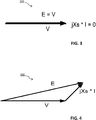
- FIG. 4 a phasor diagram 400 for 400Hz operation for a given VFG is shown.
- the example phasor diagram 400 illustrates the terminal output voltage V, a synchronous drop (jXs * I), and an internal emf E generated by the primary stator windings. Due to the load placed on the output terminals of the VFG, a synchronous reactance is realized.
- FIG. 5 a phasor diagram 500 for 800Hz operation for a given VFG is shown.
- the example phasor diagram 500 illustrates the terminal output voltage V, a synchronous voltage drop (jXs * I), and an internal emf E generated by the VFG.
- the synchronous reactance has also increases.
- the magnitude of (jXs * I) has doubled and the magnitude of the internal emf E produced by the primary stator windings is significantly larger to compensate for the synchronous reactance voltage drop.
- FIG. 4 and FIG. 5 if the load is suddenly removed from the system the overload voltage at the higher frequency is likely to cause more damage given the larger emf E.
- the disclosure provides a technique for reducing the amount of current in the main field and augmenting with a secondary stator winding that is controlled by a switch to boost the voltage produced by the primary stator windings. Efficient control over the secondary winding can be performed and can be switched quickly in response to a fault detection or sudden load removal. In the event a load is reduced or removed, the secondary stator windings can stop supplementing the emf produced by the primary stator windings and the output voltage can still be maintained. In addition, the secondary stator windings can be controlled to provide magnetic flux in whichever direction that it is needed by controlling the amount of current injected into the secondary stator windings.
- the VFG includes primary stator windings in combination with the secondary stator windings.
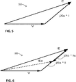
- the current is injected into the secondary stator windings to create a phasor (jXc * Ic) that is 180 degrees out of phase to jXs * I.
- the resultant Ec would be closer to E at 400Hz, the minimum frequency range.
- the control of the magnitude for (Xc * Ic) can be open-loop in nature. It can have a feed-forward style such as k * (f-400), where k is a constant, f is the VFG frequency, and 400Hz is the reference frequency.
- the operation of the secondary stator windings reduces the electromotive force required from the primary stator windings to maintain the needed output terminal voltage.
- FIG. 7A provides a configuration 700A for controlling aircraft VFG over voltage.
- each secondary stator winding 106 can be coupled to an individual switch for controlling each winding.
- the secondary stator windings are represented by inductors 704, where each inductor is coupled to a separate switch 702.
- the switches are controlled by a GCU which operates the switch 702 based on a PWM signal.
- the synchronous reactance and emf of the VFG can be regulated by a set of magnetically coupled stator windings that are PWM switched with a semiconductor switch.
- each of the secondary stator windings 106 is coupled to a common or a single switch.
- the configuration of 700B represents each winding of the secondary stator winding as an inductor 704, where each inductor 704 is coupled to a common switch 702.
- the switch is a PWM controlled switch being controlled by a GCU to vary the PWM signal supplied to the secondary stator windings.
- FIG. 8A a first switch configuration 800A for controlling aircraft VFG over-voltage is shown.
- the first configuration 800A includes two transistors that are coupled together in series that can be connected to each individual winding of the secondary winding.
- FIG. 8B provides a second configuration 800B for controlling aircraft VFG over-voltage.
- the configuration 800B is similar to 800A however the position of the two transistors is reversed.
- FIG. 8C provides a different configuration for controlling aircraft VFG over-voltage.
- FIG. 8D a configuration 800D for a single common switch for controlling aircraft over-voltage is shown.
- the switch configuration 800D can be couple to the secondary stator windings 106 as shown in FIG. 1 .
- FIG. 9A a graph 900A for controlling VFG over-voltage is shown.
- Graph 900A provides the equivalent stator synchronous inductance against the PWM duty cycle.
- Three graphs are shown.
- the first graph 904 provides the result of the VFG operating at 400Hz.
- a second graph 906 provides the result of the VFG operating at 600Hz.
- a third chart 908 provides the result of the VFG operating at 800Hz. As shown in the three graphs, as the PWM duty increases the synchronous inductance of the stator is reduced.
- FIG. 9B illustrates a different graph 900B for controlling VFG over-voltage.
- Graph 900B provides three different graphs of the equivalent stator reactance against the PWM duty for operating the VFG at different frequencies.
- a first graph 914 provides the operation of the VFG at 400Hz.
- a second graph 916 provides the result of the operation at 600Hz.
- a third graph 918 provides the result of operation at 800Hz.
- Graph 900B illustrates that as the frequency increases the synchronous reactance increases for a given PWM duty cycle where the 400Hz reference line 910 is used. Also, as the PWM cycle increases used to control the secondary stator windings, the synchronous reactance for each graph begins to decrease.
Abstract
Description
- The present invention relates generally to electrical generators, and more particularly, the present invention relates to an apparatus and method for controlling aircraft VFG over-voltage under fault or load-shed.
- Power electronics play a significant role in the modern aircraft and spacecraft industry. Generators can be used to convert mechanical energy into electrical energy to provide electrical power to various systems. Fixed frequency generators and variable frequency generators (VFG) can be used to provide power to the aircraft. The output power of the VFG is a function of the rotational speed of the generator and the connected load. A constant output voltage must be supplied by the generator in order to be usable by the aircraft's electronics. The size of the components of electronics determines the high voltage capacity and maximum level capability of the power system. Systems can be designed to withstand faults and over-voltages that can occur.
- An embodiment includes a system for controlling aircraft VFG over-voltage under fault or load-shed. The system includes a control unit for generating signals to maintain a terminal output voltage and frequency, and a variable frequency generator, coupled to the control unit, for generating the terminal output voltage. The variable frequency generator includes a stator having a set of primary stator windings and a set of secondary stator windings for generating the terminal output voltage, and a switch coupled to the set of secondary stator windings, the switch is configured to operate at a threshold frequency of the VFG to regulate the terminal output voltage by supplementing the terminal output voltage produced by the set of primary stator windings reducing the VFG fault over-voltage.
- Another embodiment includes a method for controlling aircraft VFG over-voltage under fault or load-shed. The method includes generating signals, by a control unit, to maintain a terminal output voltage and frequency of the VFG, and generating, by the VFG, the terminal output voltage. The VFG includes a stator having a set of primary stator windings and a set of secondary stator windings for generating the terminal output voltage. The method includes operating a switch coupled to the set of secondary stator windings, the switch being configured to operate at a threshold frequency of the VFG, to regulate the terminal output voltage by supplementing the terminal output voltage produced by the set of primary stator windings reducing the VFG fault over-voltage.
- The subject matter which is regarded as the present disclosure is particularly pointed out and distinctly claimed in the claims at the conclusion of the specification. The foregoing and other features, and advantages of the present disclosure are apparent from the following detailed description taken in conjunction with the accompanying drawings in which:
-
FIG. 1 illustrates a system for controlling aircraft variable frequency generator VFG over-voltage under fault or load-shed; -
FIG. 2A and 2B illustrate a model for controlling aircraft VFG over-voltage under fault or load-shed; -
FIG. 3, 4 ,5, and 6 illustrate phasor diagrams for controlling aircraft VFG over-voltage under fault or load-shed; -
FIG. 7A and 7B illustrate a configuration for controlling aircraft VFG over-voltage under fault or load-shed; -
FIG. 8A, 8B, 8C, and 8D illustrate various switch types for controlling aircraft VFG over-voltage under fault or load-shed; and -
FIG. 9A and 9B illustrate a graph for controlling aircraft VFG over-voltage under fault or load-shed. - A prior art generating system including a variable Frequency generator (VFG) controlled by a generator control unit (GCU) for generating variable frequency constant voltage power for driving aircraft loads. Large portion of the VFG loads are electronic type of loads.
- In the cases of fixed frequency generators, the generator generates relatively moderate over-voltages under fault. However, in cases using VFGs, the varying speed affects the frequency of the terminal output voltage, which in turn affects the output voltage level.
- A generator produces internal electromotive force (emf) E that is continuously regulated by a GCU to maintain a constant terminal voltage V. Under a no-load condition, E = V because voltage drop over synchronous reactance (that is, the total effects of the stator winding reactance and armature reactance) is zero. Under load conditions, when load current is not zero, and hence the reactance drop is not zero, the emf E is increased automatically by the GCU to compensate for the voltage drop so that the terminal voltage can be maintained. For a generator designed for a fixed 400Hz frequency, the stator core size and windings can be selected to limit the ability of the generator to produce an emf E higher than the permissible maximum voltage limit of the electrical system it powers.
- For generators designed to operate over a frequency range different challenges are presented. Due to higher synchronous reactance voltage drops, a higher internal emf is needed (as illustrated in
FIG. 5 and FIG. 6 ) to maintain fixed terminal output voltage at higher frequencies. The risk of higher over-voltage faults can realized at higher frequencies when compared to operating at low or minimum frequency of the system. - Issues can arise when a load on the generator is suddenly reduced or removed. This issue can be compounded when used in conjunction with a variable speed generator. Such generators produce an output from the main stator windings over a wide frequency range (for example, 400 Hertz (Hz) to 800Hz). The generator is designed to provide the desired regulated voltage for a full load at the lower end of the frequency range and therefore has a much higher output voltage capability at the higher end of the frequency range.
- When the load is suddenly reduced or removed, the generator terminal output voltage rises to a level close to the internal emf or E if the generator core is not saturated. At higher frequency (
Fig 5 ) the internal emf E can be significantly higher than that at low frequency (Fig 4 ) therefore the terminal voltage at fault can be much higher. This can lead to transient over-voltages which are beyond permissible levels and can cause damage to equipment supplied by the generator. - In an embodiment, if the internal emf Ec is maintained closer to a lower magnitude under all operating frequencies, the fault voltage and fault current would be reduced to a similar corresponding level of those under fixed frequency generator cases (for example, as illustrated by the dashed lines in
FIG. 6 ). The peak fault current seen by power electronic devices would be lower (the same as that in fixed frequency generator) therefore component size and costs for all line-replacement units in the power system can be reduced. - The terminal output voltage of the generator can be configured for various applications. In one or more embodiments, aircraft applications can use 115 volts (V). As a load is placed on the terminals of the generator, the output voltage will begin to drop. In an effort to maintain the output voltage, the current of the rotor can be increased to compensate for the reduced output voltage. This current can boost the output voltage of the generator to 115 V.
- In VFGs, at higher frequencies, the danger is realized at the highest speed when the load is suddenly removed. The spike in voltage becomes even higher when compared to operating at the lowest speed. The connected equipment will no longer be able to withstand the spike at the highest speed. If the connected equipment is designed to saturate at a low speed, the issue becomes critical. This occurs because there is an excessive amount of current remaining in the field and stator windings and cannot be removed fast enough to bring the voltage down to avoid damage to the connected equipment.
- Using the technique described herein, the current supplied to the main field and the operation of GCU is unaffected and untapped with. Instead, a set of secondary stator windings of smaller size with different equivalent wire gauge or number of turns is used and these windings are switched by a set of switches to offset the "armature reaction" effects or the effective synchronous reactance of the stator windings. This is illustrated in
Fig. 2A, Fig. 2B and dashed line inFig. 6 . This allows for the output voltage of the generator to be controlled, while reducing the risk of over-voltage. - In one or more embodiments, power electronic switches connected to the VFG would have to be sized for peak transient fault current (Epk/Ls). At 800Hz this value can be very high as explained.
- Now referring to
FIG. 1 astator 102 of asystem 100 for controlling aircraft VFG over-voltage under fault or load-shed. Thestator 102 of a VFG includes a set ofprimary stator windings 104 and a set ofsecondary stator windings 106. The secondary stator windings are coupled to aswitch 108 that is used to regulate the synchronous reactance voltage drop (jXs*I) and the emf (E) of the generator. In one or more embodiments, the switch can be a PWM controlled insulated-gate bipolar transistor IGBT switch. In a different embodiment, the switch can be other type of semiconductor switches. Thesecondary stator windings 106 can be controlled by a control unit. - In one or more embodiments, the VFG can operate between 400Hz and 800Hz. Under normal operation, the
primary stator windings 104 will provide the emf needed for operation. As the frequency of the VFG increases, thesecondary stator windings 106 will be switched to supplement the emf generated by the primary stator windings 104. In one or more embodiments, when the frequency exceeds a configurable threshold, thesecondary stator windings 106 will be switched to supplement the emf generated by the primary stator windings 104. As thesecondary stator windings 106 supplement the primary stator winding 104, theprimary stator windings 104 are no longer required to produce as much emf at the higher frequency, thus reducing the risk of over-voltage. Thesecondary stator windings 106 are controlled by theswitch 108. Current is injected into thesecondary stator windings 106, under the control of theswitch 108, to generate the voltage needed. If a fault is detected, theswitch 108 is operated to prevent the flow of current to the set ofsecondary windings 106 and the terminal output voltage is maintained using the set of primary stator windings. - In the event a fault or sudden removal of a load is detected by the VFG, the
switch 108 can control thesecondary stator windings 106 to stop generating the emf to supplement the emf generated by theprimary windings 104 by controlling the amount of current supplied to thesecondary stator windings 106. This allows the VFG to quickly and efficiently control the terminal output voltage using thesecondary stator windings 106 andswitch 108. - In one or more embodiments, the
switch 108 can be controlled to increase emf generated by thesecondary stator windings 106 as the frequency increases to maintain the output terminal voltage by injecting current into the secondary stator windings. - In one or more embodiments, a PWM switch is used and the PWM duty cycle can be increased/decreased as the frequency changes to regulate the reactance at the same value at different frequencies. This configuration allows for the internal emf to be maintained closer to a lower magnitude under all operating frequencies to effectively reduce the fault voltage and fault current. In one or more embodiments, the separate set of secondary stator windings can be used to regulate the synchronous reactance drop so that the total E is maintained at the substantially the same magnitude as that under 400Hz case.
- In this case, there is another 3-phase winding that is used to generate power. Inverters can be used to inject current into the secondary 3-phase winding to control the supplemental emf. An inverter can be used to control the current injected into the secondary winding.
- In one or more embodiments, the stator windings can include various wire gauge sizes and the stator windings can have a different number of turns. In one or more embodiments, the primary stator windings of the stator uses a larger wire gauge size than the secondary stator windings and the secondary windings have a higher number of turns.
- In a different embodiment, the system can be coupled with a permanent magnet generator (PMG) to stop the PMG from generating fault voltage and current, or regulate transient faults.
- In one or more embodiments, the generator can be designed for a fixed frequency. That is the stator core size and windings can be selected to achieve a desired performance. In an embodiment, the generator can be designed for a fixed 400Hz frequency.
- In one or more embodiments, power electronic switches connected to the VFG can be sized for peak transient fault current (Epk/Ls). At increased frequencies, e.g. 800Hz, this value can be very high as explained.
- Referring to
FIG. 2A , amodel 200A for controlling aircraft VFG overload under over-voltage or load-shed is provided. Themodel 200A provides a configuration for a set of magnetically coupled stator windings (Lc and Ls) that can be switched by the semiconductor switch SW. M represents the magnetically coupled stator windings. In an embodiment, the switch SW is a PWM controlled switch. The synchronous reactance (jXs * I) and emf (E) can be regulated by using the set of windings that is PWM switched.FIG. 2B provides anequivalent model 200B forFIG. 2A when the coupled inductor is partially shorted by a PWM controlled switch. - Referring to
FIG. 3 , a phasor diagram 300 for controlling aircraft over-voltage is shown. Under a no-load condition, the internal emf E is equal to the terminal output voltage V (E = V) because the voltage drop over synchronous reactance is zero.FIG. 3 depicts the no-load condition as shown the E vector and V vector (overlaid upon one another) are the same magnitude and are in the same direction resulting in the synchronous reactance (jXs * I) is zero. However, as the frequency of the VFG increases, the synchronous reactance also increases. In turn, the emf E must be increased to overcome the increase in the synchronous reactance drop to maintain the terminal output voltage. - Now referring to
FIG. 4 , a phasor diagram 400 for 400Hz operation for a given VFG is shown. The example phasor diagram 400 illustrates the terminal output voltage V, a synchronous drop (jXs * I), and an internal emf E generated by the primary stator windings. Due to the load placed on the output terminals of the VFG, a synchronous reactance is realized. - Now referring to
FIG. 5 , a phasor diagram 500 for 800Hz operation for a given VFG is shown. The example phasor diagram 500 illustrates the terminal output voltage V, a synchronous voltage drop (jXs * I), and an internal emf E generated by the VFG. In this example, as the frequency increased from 400Hz to 800Hz the synchronous reactance has also increases. The magnitude of (jXs * I) has doubled and the magnitude of the internal emf E produced by the primary stator windings is significantly larger to compensate for the synchronous reactance voltage drop. As shown by comparing the phasor diagrams ofFIG. 4 andFIG. 5 , if the load is suddenly removed from the system the overload voltage at the higher frequency is likely to cause more damage given the larger emf E. - In this particular instance, there is a substantial amount of current remaining in the rotor winding and is not removed or discharged fast enough to avoid damaging the connected equipment. Therefore, the disclosure provides a technique for reducing the amount of current in the main field and augmenting with a secondary stator winding that is controlled by a switch to boost the voltage produced by the primary stator windings. Efficient control over the secondary winding can be performed and can be switched quickly in response to a fault detection or sudden load removal. In the event a load is reduced or removed, the secondary stator windings can stop supplementing the emf produced by the primary stator windings and the output voltage can still be maintained. In addition, the secondary stator windings can be controlled to provide magnetic flux in whichever direction that it is needed by controlling the amount of current injected into the secondary stator windings.
- Referring now to
FIG. 6 , a phasor diagram 600 for controlling aircraft VFG over voltage is shown. The VFG includes primary stator windings in combination with the secondary stator windings. - As the secondary stator windings are operating, less exciter current is needed in the primary stators windings to maintain the terminal output voltage, therefore reducing the risk of over voltage and over current damage. In one or more embodiments, the current is injected into the secondary stator windings to create a phasor (jXc * Ic) that is 180 degrees out of phase to jXs * I. The resultant Ec would be closer to E at 400Hz, the minimum frequency range. The control of the magnitude for (Xc * Ic) can be open-loop in nature. It can have a feed-forward style such as k * (f-400), where k is a constant, f is the VFG frequency, and 400Hz is the reference frequency. The operation of the secondary stator windings reduces the electromotive force required from the primary stator windings to maintain the needed output terminal voltage.
-
FIG. 7A provides aconfiguration 700A for controlling aircraft VFG over voltage. In this configuration, each secondary stator winding 106 can be coupled to an individual switch for controlling each winding. Inconfiguration 700A the secondary stator windings are represented byinductors 704, where each inductor is coupled to aseparate switch 702. In an embodiment, the switches are controlled by a GCU which operates theswitch 702 based on a PWM signal. The synchronous reactance and emf of the VFG can be regulated by a set of magnetically coupled stator windings that are PWM switched with a semiconductor switch. - Now referring to
FIG. 7B , adifferent configuration 700B for controlling aircraft VFG over-voltage is shown. In this particular configuration, each of thesecondary stator windings 106 is coupled to a common or a single switch. The configuration of 700B represents each winding of the secondary stator winding as aninductor 704, where eachinductor 704 is coupled to acommon switch 702. In an embodiment, the switch is a PWM controlled switch being controlled by a GCU to vary the PWM signal supplied to the secondary stator windings. - Referring now to
FIG. 8A , afirst switch configuration 800A for controlling aircraft VFG over-voltage is shown. Thefirst configuration 800A includes two transistors that are coupled together in series that can be connected to each individual winding of the secondary winding.FIG. 8B provides asecond configuration 800B for controlling aircraft VFG over-voltage. Theconfiguration 800B is similar to 800A however the position of the two transistors is reversed.FIG. 8C provides a different configuration for controlling aircraft VFG over-voltage. - Referring now to
FIG. 8D , aconfiguration 800D for a single common switch for controlling aircraft over-voltage is shown. Theswitch configuration 800D can be couple to thesecondary stator windings 106 as shown inFIG. 1 . - Now referring to
FIG. 9A , agraph 900A for controlling VFG over-voltage is shown.Graph 900A provides the equivalent stator synchronous inductance against the PWM duty cycle. Three graphs are shown. Thefirst graph 904 provides the result of the VFG operating at 400Hz. Asecond graph 906 provides the result of the VFG operating at 600Hz. Athird chart 908 provides the result of the VFG operating at 800Hz. As shown in the three graphs, as the PWM duty increases the synchronous inductance of the stator is reduced. -
FIG. 9B illustrates adifferent graph 900B for controlling VFG over-voltage.Graph 900B provides three different graphs of the equivalent stator reactance against the PWM duty for operating the VFG at different frequencies. Afirst graph 914 provides the operation of the VFG at 400Hz. Asecond graph 916 provides the result of the operation at 600Hz. Athird graph 918 provides the result of operation at 800Hz.Graph 900B illustrates that as the frequency increases the synchronous reactance increases for a given PWM duty cycle where the400Hz reference line 910 is used. Also, as the PWM cycle increases used to control the secondary stator windings, the synchronous reactance for each graph begins to decrease. - While the present disclosure has been described in detail in connection with only a limited number of embodiments, it should be readily understood that the present disclosure is not limited to such disclosed embodiments. Rather, the present disclosure can be modified to incorporate any number of variations, alterations, substitutions or equivalent arrangements not heretofore described, but which are commensurate with the scope of the present invention as defined by the claims. Additionally, while various embodiments of the present disclosure have been described, it is to be understood that aspects of the present disclosure may include only some of the described embodiments. Accordingly, the present disclosure is not to be seen as limited by the foregoing description, but is only limited by the scope of the appended claims.
Claims (13)
- A system for controlling aircraft variable frequency generator VFG over voltage under fault or load-shed, the system comprising:a control unit for generating signals to maintain a terminal output voltage and frequency; anda variable frequency generator, coupled the control unit, for generating the terminal output voltage, the variable frequency generator comprising:a stator (102) comprising a set of primary stator windings (104) and a set of secondary stator windings (106) for generating the terminal output voltage; anda switch (108) coupled to the set of secondary stator windings, the switch is configured to operate at a threshold frequency of the VFG to regulate the terminal output voltage by supplementing the terminal output voltage produced by the set of primary stator windings reducing the VFG fault over-voltage.
- The system of claim 1, wherein each secondary stator winding (106) is coupled to and controlled by at least one of individual switches or by a single common switch.
- The system of claim 1 or 2, wherein the switch (108) is a pulse-width modulated PWM controlled switch.
- The system of any preceding claim, wherein the control unit is a generator control unit for controlling the set of primary stator windings and the switch coupled to the set of secondary stator windings.
- The system of any preceding claim, wherein the set of secondary stator windings (106) comprises a wire gauge or number of strands in hand different than that used in the primary stator windings, and the secondary stator windings comprises a different number of turns than the primary stator windings.
- The system of claim 1, configured to operate the VFG above a configurable threshold frequency, the set of secondary stator windings supplement the set of primary stator windings by reducing an amount of exciter current supplied to the set of primary stator windings and increasing the amount of exciter current suppled to the set of secondary stator windings while maintaining the terminal output voltage.
- A method for controlling aircraft variable frequency generator VFG over voltage under fault or load-shed, the method comprising:generating signals, by a control unit, to maintain a terminal output voltage and frequency of the VFG;generating, by the VFG, the terminal output voltage, the VFG comprising a stator comprising a set of primary stator windings and a set of secondary stator windings for generating the terminal output voltage; andoperating a switch coupled to the set of secondary stator windings, the switch being configured to operate at a threshold frequency of the VFG to regulate the terminal output voltage by supplementing the terminal output voltage produced by the set of primary stator windings reducing the VFG fault over-voltage.
- The method of claim 7, wherein each secondary stator winding is coupled to and controlled by at least one of individual switches or a single common switch, wherein the switch is a pulse-width modulated PWM controlled switch.
- The method of claim 7 or 8, wherein the control unit is a generator control unit for controlling the set of primary stator windings and the switch coupled to the set of secondary stator windings.
- The method of any claims 7 to 9, wherein the set of secondary stator windings comprises a wire gauge or number of strands in hand different than that used in the primary stator windings, and the secondary stator windings comprises a different number of turns than the primary stator windings.
- The method of any of claims 7 to 10, further comprising operating the VFG above a configurable threshold frequency, the set of secondary stator windings supplement the set of primary stator windings by reducing an amount of exciter current supplied to the set of primary stator windings and increasing the amount of exciter current supplied to the set of secondary stator windings while maintaining the terminal output voltage.
- The method of any of claims 7 to 11, wherein the terminal output voltage is regulated by adjusting the PWM duty cycle of the switch controlling the set of secondary stator windings, wherein the adjustment of the PWM duty cycle is based on the frequency of the VFG.
- The method of any of claims 7 to 12, responsive to detecting a fault, operating the switch to prevent a supply of current to the set of secondary windings and maintaining the terminal output voltage using the set of primary windings.
Applications Claiming Priority (1)
| Application Number | Priority Date | Filing Date | Title |
|---|---|---|---|
| US15/387,923 US10044305B2 (en) | 2016-12-22 | 2016-12-22 | Controlling aircraft VFG over voltage under fault or load-shed |
Publications (1)
| Publication Number | Publication Date |
|---|---|
| EP3340455A1 true EP3340455A1 (en) | 2018-06-27 |
Family
ID=60957042
Family Applications (1)
| Application Number | Title | Priority Date | Filing Date |
|---|---|---|---|
| EP17210066.1A Pending EP3340455A1 (en) | 2016-12-22 | 2017-12-22 | Controlling aircraft vfg over voltage under fault or load-shed |
Country Status (2)
| Country | Link |
|---|---|
| US (1) | US10044305B2 (en) |
| EP (1) | EP3340455A1 (en) |
Citations (5)
| Publication number | Priority date | Publication date | Assignee | Title |
|---|---|---|---|---|
| US20020163262A1 (en) * | 2001-05-04 | 2002-11-07 | Chun-Pu Hsu | High performance stator device |
| US20120286523A1 (en) * | 2011-05-10 | 2012-11-15 | The Boeing Company | Reconfigurable stators |
| DE102015208302A1 (en) * | 2014-07-25 | 2016-01-28 | Robert Bosch Gmbh | Method for operating an at least generator-operable electric machine and means for implementing it |
| US20160043601A1 (en) * | 2012-08-30 | 2016-02-11 | Megumi KAWAMURA | Permanent-magnet ac power generator |
| US20160204728A1 (en) * | 2015-01-14 | 2016-07-14 | Hitachi, Ltd. | Permanent Magnet Synchronous Motor and Winding-Switching Motor Driving Device, and Refrigeration Air Conditioner and Electric Vehicle Using Same |
Family Cites Families (18)
| Publication number | Priority date | Publication date | Assignee | Title |
|---|---|---|---|---|
| US4812729A (en) * | 1986-08-19 | 1989-03-14 | Hitachi Ltd. | Protecting apparatus for secondary excitation type variable speed AC generator/motor |
| US4894602A (en) * | 1988-06-02 | 1990-01-16 | Brunswick Corporation | Overvoltage protection system for marine ignition and regulator circuitry |
| US5153498A (en) | 1989-11-07 | 1992-10-06 | Sundstrand Corporation | Generic control unit |
| US5083077A (en) * | 1990-07-31 | 1992-01-21 | The State Of Oregon Acting By And Through The State Board Of Higher Education On Behalf Of Oregon State University | Brushless doubly-fed generation system for vehicles |
| GB9412410D0 (en) | 1994-06-21 | 1994-08-10 | Lucas Ind Plc | Control circuit for electrical generator |
| US5900722A (en) * | 1994-09-14 | 1999-05-04 | Coleman Powermate, Inc. | Multimode power converter |
| US5801460A (en) | 1996-07-18 | 1998-09-01 | Sundstrand Corporation | Electrical power transmitting system with reduced feeder size and method of operation |
| US6181112B1 (en) | 1998-12-10 | 2001-01-30 | Hamilton Sundstrand Corporation | Apparatus and method for limiting generator peak voltage |
| US6713889B2 (en) * | 2001-04-27 | 2004-03-30 | Siemens Aktiengesellschaft | Motor-generator system for a motor vehicle with hybrid traction drive |
| GB0206368D0 (en) | 2002-03-18 | 2002-05-01 | Lucas Industries Ltd | Reactive power control |
| US6960900B2 (en) * | 2003-11-28 | 2005-11-01 | General Electric Company | Method and apparatus for starting a gas turbine using a polyphase electric power generator |
| US7952316B2 (en) * | 2007-04-27 | 2011-05-31 | Honeywell International, Inc. | Variable frequency reduced speed variation electric drive |
| EP2463976A1 (en) * | 2010-12-08 | 2012-06-13 | Siemens Aktiengesellschaft | Circuit and method for regulating a DC voltage and power con-verter |
| DE102012201097A1 (en) * | 2012-01-26 | 2013-08-01 | Robert Bosch Gmbh | Overvoltage protection device for an electric drive |
| US9257889B2 (en) | 2013-03-15 | 2016-02-09 | Hamilton Sundstrand Corporation | EPGS architecture with multi-channel synchronous generator and common field regulated exciter |
| US9531247B2 (en) * | 2014-04-04 | 2016-12-27 | Raytheon Company | Inertial energy storage system and hydro-fluoro-ether power transformer scheme for radar power systems and large PFN charging |
| EP3164935A4 (en) * | 2014-07-02 | 2018-02-28 | GE Energy Power Conversion Technology Ltd | Overvoltage protection self-trigger circuit for double fed induction generator (dfig) wind power system |
| DE102014222163A1 (en) * | 2014-07-25 | 2016-01-28 | Robert Bosch Gmbh | Electric machine for supplying energy to a motor vehicle electrical system |
-
2016
- 2016-12-22 US US15/387,923 patent/US10044305B2/en active Active
-
2017
- 2017-12-22 EP EP17210066.1A patent/EP3340455A1/en active Pending
Patent Citations (5)
| Publication number | Priority date | Publication date | Assignee | Title |
|---|---|---|---|---|
| US20020163262A1 (en) * | 2001-05-04 | 2002-11-07 | Chun-Pu Hsu | High performance stator device |
| US20120286523A1 (en) * | 2011-05-10 | 2012-11-15 | The Boeing Company | Reconfigurable stators |
| US20160043601A1 (en) * | 2012-08-30 | 2016-02-11 | Megumi KAWAMURA | Permanent-magnet ac power generator |
| DE102015208302A1 (en) * | 2014-07-25 | 2016-01-28 | Robert Bosch Gmbh | Method for operating an at least generator-operable electric machine and means for implementing it |
| US20160204728A1 (en) * | 2015-01-14 | 2016-07-14 | Hitachi, Ltd. | Permanent Magnet Synchronous Motor and Winding-Switching Motor Driving Device, and Refrigeration Air Conditioner and Electric Vehicle Using Same |
Also Published As
| Publication number | Publication date |
|---|---|
| US20180183371A1 (en) | 2018-06-28 |
| US10044305B2 (en) | 2018-08-07 |
Similar Documents
| Publication | Publication Date | Title |
|---|---|---|
| US8427116B2 (en) | Starting/generating system with multi-functional circuit breaker | |
| US8970183B2 (en) | Overvoltage limiter in an aircraft electrical power generation system | |
| JP5014437B2 (en) | Low voltage ride-through system for a variable speed wind turbine having an exciter and a power converter not connected to the transmission system | |
| US8975876B2 (en) | Method of controlling rotating main field converter | |
| US9054610B2 (en) | Generator architecture with main field rotating power converter | |
| JP5207985B2 (en) | Control method and control system for double-fed asynchronous wind generator converter | |
| US9325229B2 (en) | Generator architecture with PMG exciter and main field rotating power converter | |
| JPH10164899A (en) | Step-up and step-down chopper method stop type excitation system for synchronous generator | |
| US8823208B2 (en) | Self-energizing voltage regulator with improved transient recovery | |
| EP2045910B1 (en) | Starter/generator system with control to address a voltage rise | |
| EP3270507B1 (en) | Exciter drive circuit including configurable flyback unit with fast energy field collapse | |
| JP2004523997A (en) | Acceleration of transients during generator unloading | |
| EP3644485B1 (en) | Control of an electrical power system responsive to sensing a ground fault | |
| JP2004153988A (en) | Stopping type exciting system | |
| EP3340455A1 (en) | Controlling aircraft vfg over voltage under fault or load-shed | |
| JP2015065788A (en) | Rotary electric machine for vehicle | |
| JP4822138B2 (en) | Power generation system and operation method thereof | |
| JP2011155818A (en) | Control apparatus for constant voltage in permanent-magnet generator | |
| TWI574501B (en) | Control circuit of alternator | |
| CN117413457A (en) | Method for operating a generator unit and safety shut-off assembly | |
| JP2018050399A (en) | Field winding-type synchronous electric machine and control method |
Legal Events
| Date | Code | Title | Description |
|---|---|---|---|
| PUAI | Public reference made under article 153(3) epc to a published international application that has entered the european phase |
Free format text: ORIGINAL CODE: 0009012 |
|
| STAA | Information on the status of an ep patent application or granted ep patent |
Free format text: STATUS: THE APPLICATION HAS BEEN PUBLISHED |
|
| AK | Designated contracting states |
Kind code of ref document: A1 Designated state(s): AL AT BE BG CH CY CZ DE DK EE ES FI FR GB GR HR HU IE IS IT LI LT LU LV MC MK MT NL NO PL PT RO RS SE SI SK SM TR |
|
| AX | Request for extension of the european patent |
Extension state: BA ME |
|
| STAA | Information on the status of an ep patent application or granted ep patent |
Free format text: STATUS: REQUEST FOR EXAMINATION WAS MADE |
|
| 17P | Request for examination filed |
Effective date: 20181224 |
|
| RBV | Designated contracting states (corrected) |
Designated state(s): AL AT BE BG CH CY CZ DE DK EE ES FI FR GB GR HR HU IE IS IT LI LT LU LV MC MK MT NL NO PL PT RO RS SE SI SK SM TR |
|
| STAA | Information on the status of an ep patent application or granted ep patent |
Free format text: STATUS: REQUEST FOR EXAMINATION WAS MADE |
|
| STAA | Information on the status of an ep patent application or granted ep patent |
Free format text: STATUS: EXAMINATION IS IN PROGRESS |
|
| 17Q | First examination report despatched |
Effective date: 20210514 |
|
| STAA | Information on the status of an ep patent application or granted ep patent |
Free format text: STATUS: EXAMINATION IS IN PROGRESS |