EP2562807A1 - Heat transfer in an electronic device - Google Patents
Heat transfer in an electronic device Download PDFInfo
- Publication number
- EP2562807A1 EP2562807A1 EP11178270A EP11178270A EP2562807A1 EP 2562807 A1 EP2562807 A1 EP 2562807A1 EP 11178270 A EP11178270 A EP 11178270A EP 11178270 A EP11178270 A EP 11178270A EP 2562807 A1 EP2562807 A1 EP 2562807A1
- Authority
- EP
- European Patent Office
- Prior art keywords
- carbon fibers
- heat transfer
- transfer element
- heat
- electronic device
- Prior art date
- Legal status (The legal status is an assumption and is not a legal conclusion. Google has not performed a legal analysis and makes no representation as to the accuracy of the status listed.)
- Withdrawn
Links
Images


Classifications
-
- H—ELECTRICITY
- H01—ELECTRIC ELEMENTS
- H01L—SEMICONDUCTOR DEVICES NOT COVERED BY CLASS H10
- H01L23/00—Details of semiconductor or other solid state devices
- H01L23/34—Arrangements for cooling, heating, ventilating or temperature compensation ; Temperature sensing arrangements
- H01L23/36—Selection of materials, or shaping, to facilitate cooling or heating, e.g. heatsinks
- H01L23/373—Cooling facilitated by selection of materials for the device or materials for thermal expansion adaptation, e.g. carbon
-
- H—ELECTRICITY
- H01—ELECTRIC ELEMENTS
- H01L—SEMICONDUCTOR DEVICES NOT COVERED BY CLASS H10
- H01L2924/00—Indexing scheme for arrangements or methods for connecting or disconnecting semiconductor or solid-state bodies as covered by H01L24/00
- H01L2924/0001—Technical content checked by a classifier
- H01L2924/0002—Not covered by any one of groups H01L24/00, H01L24/00 and H01L2224/00
Definitions
- the present invention relates to heat transfer mechanisms in electronic devices and in particular to an electronic device that comprises at least one heat dissipating component and a heat transfer element connected to the heat dissipating component.
- Such devices are in particular devices that include power electronic components.
- One particular example is a frequency converter.
- Thermal management and specifically cooling of electronic devices is a major topic for a safe, reliable and efficient component operation. There is a challenge of proposing thermal solutions that are able to answer to constant increase in the power density at component level and at device level.
- the cooling mode of devices can be classified generically as: convection, radiation, conduction. Additionally, convection can be reached by single phase or two-phase flow.
- the cooling arrangements typically use fluids and fluid flows or solid materials that have a sufficiently high thermal conductivity.
- the most common examples of such solid materials are aluminum and copper.
- the reason for using aluminum and copper is that the material needs to have good thermally conductive properties and at the same time good mechanical properties for mechanical stability and reliable operation of the device. For thermal management any material with good mechanical properties, high thermal conductivity and sometimes also low density would be suitable for thermal management.
- WO 2011/037578 A1 discloses a further heat transfer apparatus.
- the heat transfer apparatus includes a thermal conduit that can be disposed at least partially within an electronic device enclosure.
- a non-heat conductive material can be disposed at least partially about at least a portion of the thermal conduit.
- the thermal conduit can be a material having a high thermal conductivity, for example aluminum, aluminum alloy, a copper or copper alloy.
- the non-heat conductive material can include asbestos, carbon fiber, silica, diatomaceous earth, cork, wool, cotton, plastics, fiberglass, mineral wool, polystyrene, combinations thereof, and the like.
- the object of the invention is achieved by providing the heat transfer element with carbon fibers that are arranged along the desired thermal path. This provides a good thermal conductivity in the desired direction and relatively lower conductivity in the direction perpendicular to the thermal path.
- the invention is based on providing the heat transfer element with carbon fibers that are arranged along the desired thermal path.
- This has the effect that the longitudinal direction of the fibers is substantially parallel to the direction of the thermal path.
- the carbon fibers are not randomly distributed as in the prior art but are substantially parallel to each other.
- This has the effect that in the direction of the thermal path, the thermal conductivity is facilitated by the relatively high thermal conductivity of the carbon fibers whereas in the transverse direction, the thermal conductivity is lower because of the gaps and interfaces between the parallel carbon fibers.
- This arrangement provides a good thermal conductivity in the desired direction and relatively lower conductivity in the direction perpendicular to the thermal path.
- Carbon fibers exhibit high thermal conductivity up to 1100 [W/mK], for instance. High alignment in the fibers indicates that perpendicularly to the fibers themselves, the thermal conductivity is much lower and can range between 3 and 10 [W/mK], for instance.
- the carbon fibers are embedded in a resin during the process of generation of a suitable geometry of the heat transfer element.
- a composite structure with a resin type EX1515 is provided and then the thermal conductivity perpendicularly to the fiber direction is 1.2 [W/mK] and 360 [W/mK] in the fiber direction.
- the thermal conductivity of the heat transfer element is more than 100 [W/mK] in the fiber direction, i.e. in the direction of the thermal path.
- the thermal conductivity along the thermal path can range between 200 and 1 000 [W/mK], for instance.
- the thermal conductivity of the heat transfer element perpendicularly to the fiber direction is usually less than 50 [W/mK], such as less than 10 [W/mK], and in advantageous embodiments less than 2 [W/mK], for instance.
- thermal conductivity is for example 10 times higher in the direction of the desired thermal path than in the direction perpendicular to the thermal path.
- This factor can also be higher, such as 100 or 250 or even 400. In the above-referred example using resin type EX1515, the factor is 300.
- Table 1 Thermal conductivity of fiber type K13C (Mitsubishi Chemical America) as a fiber and in composite with resin EX1515 (TENCATE ADVANCED COMPOSITES USA, INC.).
- pitch based carbon fibers are used for aeronautics applications, not only for their thermal properties but also due to the low coefficient of thermal expansion and the ultra high stiffness of the fibers. Also the light weight and ultra-high stiffness of the fibers could be useful in some applications, for example when the heat transfer elements are incorporated in fast moving parts, like in robotics.
- Pitch based carbon fibers are also used in compression molding compounds to make more complex structures, like it could be required for housings. Compared to woven fabric or unidirectional fibers, molding compounds have shorter fiber length and the fibers are after compression molding more random in the component. The in-plane thermal conductivity is therefore reduced, but the compounds can make complex structures.
- peculiar characteristics of the pitch based carbon fibers i.e. the difference in thermal conductivity in perpendicular directions, is used advantageously for specific applications where the heat should follow a certain path and direction.
- Such embodiments can effectively target the heat transport in one direction and avoiding it in the other.
- Fig. 1 shows an embodiment, comprising two heat dissipating components 1, i.e. components that dissipate so much heat during their operation that there is need to facilitate heat transfer away from the components.
- the heat dissipating components 1 are mounted on the surface of a heat transfer element 2, which includes parallel carbon fibers 5 embedded in a resin.
- Fig. 1 shows also connection areas 3 that are the areas on which the heat dissipating components 1 are mounted.
- the heat transfer element 2 has also heat dissipating areas 4 at both of its ends. A thermal path of relatively high thermal conductivity is created between the connection areas 3 and the heat dissipating areas 4 by means of the carbon fibers 5 that are generally aligned along the direction from the connection areas 3 to the heat dissipating areas 4.
- Fig. 1 The direction 6 along the thermal path is also indicated in Fig. 1 by means of an arrow.
- Fig. 1 there are also "cold” components 8, i.e. components that do not dissipate so much heat, mounted on the surface of the heat transfer element 2.
- Fig. 2 discloses an embodiment, wherein the heat dissipating component 1 and the heat transfer element 2 are enclosed within a device case 10 and the heat dissipating area 4 of the heat transfer element 2 is connected to a cold element 9 for transferring heat from the heat dissipating component 1 to the cold element 9 via the carbon fibers 5 of the heat transfer element 2.
- Fig. 3 discloses an embodiment, wherein the heat dissipating component 1 and the heat transfer element 2 are enclosed within a device case 10 and the heat dissipating area 4 of the heat transfer element 2 is connected to a heat sink 7 outside the device case 10. Then, heat is transferred from the heat dissipating component 1 to the heat sink 7 via the carbon fibers 5 of the heat transfer element 2 and will be dissipated outside the device case 10.
- the heat sink 7 comprises carbon fibers.
- the heat sink 7 and the heat transfer element 2 are made in a single piece integral heat dissipation part.
- any suitable heat sink 7 can be used in the embodiments.
- Fig. 4 discloses an embodiment, wherein the heat dissipating components 1 are mounted on a circuit board 11 and the heat transfer element 2 is placed on top of the components is a way that conforms to the shapes of the upper parts of the heat dissipating components 1. This also means that the connection areas 3 can protrude inside the heat transfer element 2.
- the direction 6 of the thermal path is substantially parallel to the width of the circuit board 11.
- Fig. 5 discloses an embodiment, wherein the heat dissipating components 1 are mounted on a circuit board 11 and individual heat transfer elements 2 are placed on top of the heat dissipating components 1. Also in this embodiment it is possible - but not necessarily a requirement - that the heat transfer elements 2 conform to the shapes of the upper parts of the heat dissipating components 1. In this embodiment, the directions 6 of the thermal paths are substantially perpendicular to the width of the circuit board 11.
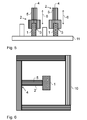
- Fig. 6 discloses an embodiment, wherein the heat dissipating component 1 and the heat transfer element 2 are enclosed within a device case 10 that has been made from a similar material than the heat transfer element 2.
- the device case 10 is a single piece part including bended carbon fibers.
- any suitable structure can be used.
- Fig. 7 discloses an embodiment, wherein the heat transfer element 2 is curved between the heat dissipating component 1 and the heat sink 7. Then, the carbon fibers 5 have been bended during the manufacture.
- Fig. 8 discloses an embodiment, wherein the heat transfer element 2 has been connected between a device 12 to be cooled and a cooling device 13.
- the heat transfer element 2 has been constructed as a layer structure having a plurality of layers of different grades of carbon fibers 5. Then, the layer adjacent to the connection area 3 can be made of more expensive carbon fibers 5 having a higher thermal conductivity and the lower layers placed on top of the first layer can be made of cheaper carbon fibers 5 that are not as effective in transferring heat. This can make the heat transfer element 2 more economical without substantially decreasing the capability to transfer heat. This is because the lower layers need not always be as effective in heat transfer as the first layer because of a temperature gradient between the layers.
- the above-described or a corresponding layer structure is made as an integral part of a printed circuit board. It is also possible to provide printed circuit boards with other kinds of heat transfer elements 2. In such embodiments, the carbon fibers 5 can also be embedded inside the circuit board substrate when manufacturing the substrate laminate.
- pitch based carbon fibers in embodiments will increase in-plane thermal conduction of the material with an increased flexibility toward shape and geometry, because the fibers can be shaped as desired.
- Some embodiments enable hot spot "management” by spreading the heat over a wide area and limiting the over temperature of electric components possibly connected to the support material.
- thermo conductors there are also embodiments that enable interconnection, by means of shaped carbon fibers, of hot and cold spots within the device.
- the shaped carbon fibers connect different parts of the devices that have different temperatures, more uniform temperature is attained and therefore thermal gradients remain smaller.
- One of the advantages compared to common thermal conductors is in the possibility of shaping the thermal conductor in almost any shape.
- the device itself may be a drive, a switch, a circuit breaker or any possible electric component that has a necessity of reducing the thermal gradients in the device by connecting spots at different locations.
- the carbon fibers 5 can be shaped for bringing the heat from the generating point to a common heat sink installed outside of the device. This may be of interest for cabinet cooling in case high IP may be required. Then, the pitch based carbon fibers may act as a "heat bus".
- the device case plays a dominant role in the heat dissipation.
- the device case can be substituted by a carbon fiber structure and the specific elements that need to be cooled can be attached directly or indirectly to it.
- pluggable carbon fiber elements and attach these over active or passive components.
- Some embodiments suggest building up part of the power module from a resin carbon fiber composition (oriented carbon fibers) to increase the thermal spreading.
- a resin carbon fiber composition oriented carbon fibers
- CTE coefficient of thermal expansion
- the thermal conductivity in the out of plane direction is much lower than in fiber direction such that the surroundings of the cooling structures are not heated as much as when using isotropic metallic cooling structures.
- the carbon fibers can be bended and then embedded in resin and the resin cured, so that the geometry can be designed in such a way that the direction of high thermal conductivity can be selected according to the need of the application.
- the resin itself can be thermoset or thermoplastic.
- the carbon fibers are insulated so that the heat transfer element can withstand some electrical field in thickness direction.
- an electronic device comprising at least one heat dissipating component 1 and a heat transfer element 2.
- the heat transfer element 2 has a connection area 3 connected to the at least one heat dissipating component 1 and also at least one heat dissipating area 4.
- the heat transfer element 2 including a thermal path from the connection area 3 to the at least one heat dissipating area 4 and further includes carbon fibers 5 arranged along the thermal path.
- At least a portion of the carbon fibers 5 are pitch based carbon fibers. In a further embodiment, all or substantially all of the carbon fibers 5 are pitch based carbon fibers.
- At least some of the carbon fibers 5 extend the entire distance from the connection area 3 to the at least one heat dissipating area 4. It is also possible that all or substantially all of the carbon fibers 5 extend the entire distance from the connection area 3 to the at least one heat dissipating area 4. However, the price of the heat transfer element 2 may sometimes be reduced by using at least some shorter fibers in addition to the longer fibers. It is also possible that the heat transfer element 2 does not have any fibers that extend the entire distance from the connection area 3 to the at least one heat dissipating area 4 but each of the fibers 5 extends only a portion of the distance from the connection area 3 to the at least one heat dissipating area 4. When the lengths of such shorter fibers overlap, heat is still effectively transferred from the connection area 3 to the at least one heat dissipating area 4.
- substantially all of the carbon fibers 5 are substantially parallel to the thermal path. At least for some applications, substantially all of the carbon fibers are parallel when for example 90 % of the total length of the carbon fibers 5 is substantially parallel to the thermal path.
- the thermal path is curved and the heat transfer element 2 includes bended carbon fibers.
- the carbon fibers 5 of the heat transfer element 2 are embedded in resin.
- the thermal conductivity of the resin is substantially lower than the thermal conductivity in the longitudinal direction of each of the carbon fibers 5.
- the thermal conductivity of the heat transfer element 2 is substantially greater in the direction 6 along the thermal path compared to the direction perpendicular to the thermal path.
- the heat transfer element 2 comprises a first layer of carbon fibers of a first grade and at least one second layer of carbon fibers of at least one second grade.
- the at least one heat dissipating area 4 is connected to a heat sink 7.
- a method of equipping an electronic device with a heat transfer element 2 Such an electronic device can have at least one heat dissipating component 1 and the heat transfer element 2 has at least one heat dissipating area 4.
- the method comprises connecting a connection area 3 of the heat transfer element 2 to the at least one heat dissipating component 1 such that the heat transfer element 2 creates a thermal path between the at least one heat dissipating component 1 and the at least one heat dissipating area 4.
- the method of making the heat transfer element 2 comprises arranging carbon fibers 5 along the thermal path.
- the method comprises using pitch based carbon fibers as the carbon fibers.
- the method comprises aligning the carbon fibers 5 with the thermal path.
- the method comprises casting resin over a plurality of parallel carbon fibers 5 to form the heat transfer element 2 such that the plurality of parallel carbon fibers 5 are at least partially within the resin.
- the method comprises bending a plurality of parallel carbon fibers (5) in a desired shape and casting resin over the bended carbon fibers 5 to form the heat transfer element 2 such that the plurality of parallel carbon fibers 5 are in the desired shape and at least partially within the resin.
- the method comprises arranging first carbon fibers of a first grade as a first layer and second carbon fibers of a second grade as at least one second layer on top of the first layer.
- Embodiments provide high thermal conductivity that will enable transfer of the heat from the device to be cooled to the cooler with a low thermal resistance.
- a composite lay-out can also be made. Then, it is preferable that the side in contact with the "to be cooled device" has the highest thermal conductivity to extract the heat. Other parts of the composite structure can have lower grade fibers.
- Embodiments provide improved thermal management and therefore enable a higher power density.
- the pitch based carbon fiber cooling structure itself does heat up the surrounding much less than aluminum or copper, for instance. Less air cooling is required as the surrounding temperature is decreased.
- Another possible advantage of some of the embodiments is increased geometrical freedom as the carbon fibers can be bended and have a high thermal conductivity only in fiber direction. Final mounting of the cooling section to a heat sink can be made on a location where it can be afforded.
- embodiments may provide competitive advantages due to the increased power density and therefore also smaller components and devices can be made.
- Embodiments may also provide improved cooling and therefore increase the component reliability and help in achieving slower thermal ageing.
Landscapes
- Engineering & Computer Science (AREA)
- Chemical & Material Sciences (AREA)
- Materials Engineering (AREA)
- Physics & Mathematics (AREA)
- Condensed Matter Physics & Semiconductors (AREA)
- General Physics & Mathematics (AREA)
- Computer Hardware Design (AREA)
- Microelectronics & Electronic Packaging (AREA)
- Power Engineering (AREA)
- Cooling Or The Like Of Semiconductors Or Solid State Devices (AREA)
- Cooling Or The Like Of Electrical Apparatus (AREA)
Abstract
Heat transfer in an electronic device by means of a heat transfer element (2) and the method of preparing such a device. The electronic device comprises at least one heat dissipating component (1) and the heat transfer element (2) has a connection area (3) connected to said at least one heat dissipating component (1). The heat transfer element (2) also has at least one heat dissipating area (4) and including a thermal path from the connection area (3) to the at least one heat dissipating area (4). The heat transfer element (2) further includes carbon fibers (5) arranged along the thermal path. According to an embodiment, the carbon fibers (5) are pitch based carbon fibers and are embedded in a resin. Then, the heat transfer element (2) can provide greater thermal conductivity in the direction (6) along the thermal path compared to the direction perpendicular to the thermal path.
Description
- The present invention relates to heat transfer mechanisms in electronic devices and in particular to an electronic device that comprises at least one heat dissipating component and a heat transfer element connected to the heat dissipating component.
- Such devices are in particular devices that include power electronic components. One particular example is a frequency converter.
- Thermal management and specifically cooling of electronic devices is a major topic for a safe, reliable and efficient component operation. There is a challenge of proposing thermal solutions that are able to answer to constant increase in the power density at component level and at device level.
- The cooling mode of devices can be classified generically as: convection, radiation, conduction. Additionally, convection can be reached by single phase or two-phase flow.
- The cooling arrangements typically use fluids and fluid flows or solid materials that have a sufficiently high thermal conductivity. The most common examples of such solid materials are aluminum and copper. The reason for using aluminum and copper is that the material needs to have good thermally conductive properties and at the same time good mechanical properties for mechanical stability and reliable operation of the device. For thermal management any material with good mechanical properties, high thermal conductivity and sometimes also low density would be suitable for thermal management.
- Also composite materials have been suggested for thermal conduction.
US 7 651 767 B2 andUS 2009/0061193 A1 disclose the use of carbon fiber reinforcement for improving thermal conductivity of a resin molded product. Carbon fiber reinforced plastic is also suggested inUS 6 259 602 B1 even though the document mainly suggests to use aluminum, copper or silver. In this document, thermal conduction is performed by a heat conductive device that has rigid regions and bendable regions. -
WO 2011/037578 A1 discloses a further heat transfer apparatus. The heat transfer apparatus includes a thermal conduit that can be disposed at least partially within an electronic device enclosure. A non-heat conductive material can be disposed at least partially about at least a portion of the thermal conduit. The thermal conduit can be a material having a high thermal conductivity, for example aluminum, aluminum alloy, a copper or copper alloy. The non-heat conductive material can include asbestos, carbon fiber, silica, diatomaceous earth, cork, wool, cotton, plastics, fiberglass, mineral wool, polystyrene, combinations thereof, and the like. - It is an object of the present invention to provide an electronic device with a new heat transfer element that has sufficiently good properties at least in view of thermal conductivity.
- Other desired properties that could be optionally achieved are e.g. suitable mechanical strength, suitable price, relatively light weight and capability to manufacture in desired shapes. Also capability to conduct heat directionally as in the above-cited
WO 2011/037578 A1 would be useful property. - The object of the invention is achieved by providing the heat transfer element with carbon fibers that are arranged along the desired thermal path. This provides a good thermal conductivity in the desired direction and relatively lower conductivity in the direction perpendicular to the thermal path.
- For a more complete understanding of the present invention and the advantages thereof, the invention is now described with the aid of the examples and with reference to the following drawings, in which:
-
Figure 1 presents an electronic device and a heat transfer element according to an embodiment; -
Figure 2 presents an electronic device and a heat transfer element according to another embodiment; -
Figure 3 presents an electronic device and a heat transfer element according to a further embodiment; -
Figure 4 presents an even further embodiment of an electronic device and a heat transfer element; -
Figure 5 presents a still further embodiment of an electronic device and a heat transfer element; -
Figure 6 presents an embodiment wherein a device case is made of material comparable to that of the heat transfer element; -
Figure 7 presents an embodiment having a curved heat transfer element; and -
Figure 8 presents an embodiment wherein the heat transfer element has a layer structure of different kinds of carbon fibers. - As described above, the invention is based on providing the heat transfer element with carbon fibers that are arranged along the desired thermal path. This has the effect that the longitudinal direction of the fibers is substantially parallel to the direction of the thermal path. Thus, when the carbon fibers are arranged along the thermal path, the carbon fibers are not randomly distributed as in the prior art but are substantially parallel to each other. This has the effect that in the direction of the thermal path, the thermal conductivity is facilitated by the relatively high thermal conductivity of the carbon fibers whereas in the transverse direction, the thermal conductivity is lower because of the gaps and interfaces between the parallel carbon fibers. This arrangement provides a good thermal conductivity in the desired direction and relatively lower conductivity in the direction perpendicular to the thermal path.
- Carbon fibers exhibit high thermal conductivity up to 1100 [W/mK], for instance. High alignment in the fibers indicates that perpendicularly to the fibers themselves, the thermal conductivity is much lower and can range between 3 and 10 [W/mK], for instance. According to an embodiment, the carbon fibers are embedded in a resin during the process of generation of a suitable geometry of the heat transfer element.
- According to an embodiment, a composite structure with a resin type EX1515 is provided and then the thermal conductivity perpendicularly to the fiber direction is 1.2 [W/mK] and 360 [W/mK] in the fiber direction.
- Usually, the thermal conductivity of the heat transfer element is more than 100 [W/mK] in the fiber direction, i.e. in the direction of the thermal path. The thermal conductivity along the thermal path can range between 200 and 1 000 [W/mK], for instance.
- The thermal conductivity of the heat transfer element perpendicularly to the fiber direction is usually less than 50 [W/mK], such as less than 10 [W/mK], and in advantageous embodiments less than 2 [W/mK], for instance.
- Thus, it is possible to produce heat transfer elements that exhibit directional heat transfer such that thermal conductivity is for example 10 times higher in the direction of the desired thermal path than in the direction perpendicular to the thermal path. This factor can also be higher, such as 100 or 250 or even 400. In the above-referred example using resin type EX1515, the factor is 300.
- Properties depend from the material grade and usually the price of the material is proportional to the quality of the grade. Usually, a lower thermal conductivity goes together with a lower price and higher thermal conductivity grades are more expensive.
Table 1 shows one example of a fiber and a resin. Material ID Thermal conductivity λ0° [W/mK] Thermal conductivity λ90° [W/mK] K13C 600 - K13C/EX1515 360 1.2 - Table 1: Thermal conductivity of fiber type K13C (Mitsubishi Chemical America) as a fiber and in composite with resin EX1515 (TENCATE ADVANCED COMPOSITES USA, INC.).
- More information relating to the fibers can be found in publication by Ozakim T; Naito, K; Mikami, I; Yamauchi, H; Tsuneta, S.: 51th High precision Composite Pipers for Solar-B Optical Structures. International Astronautical Congress, Rio de Janeiro, October 2000, which publication is incorporated herein by reference. Further information is provided also by the above-referred background art documents
US 7 651 767 B2 andUS 2009/0061193 A1 , which are also incorporated herein by reference. - As is disclosed in the above-referred Ozakim et al. publication, pitch based carbon fibers are used for aeronautics applications, not only for their thermal properties but also due to the low coefficient of thermal expansion and the ultra high stiffness of the fibers. Also the light weight and ultra-high stiffness of the fibers could be useful in some applications, for example when the heat transfer elements are incorporated in fast moving parts, like in robotics.
- Pitch based carbon fibers are also used in compression molding compounds to make more complex structures, like it could be required for housings. Compared to woven fabric or unidirectional fibers, molding compounds have shorter fiber length and the fibers are after compression molding more random in the component. The in-plane thermal conductivity is therefore reduced, but the compounds can make complex structures.
- More detailed information about the manufacturing of carbon fibers can be found in the book Morgan, P.: Carbon Fibers and Their Composites, Marcel Dekker Inc, 2005, which is incorporated herein by reference.
- According to embodiments of our invention, peculiar characteristics of the pitch based carbon fibers, i.e. the difference in thermal conductivity in perpendicular directions, is used advantageously for specific applications where the heat should follow a certain path and direction. Such embodiments can effectively target the heat transport in one direction and avoiding it in the other.
-
Fig. 1 shows an embodiment, comprising twoheat dissipating components 1, i.e. components that dissipate so much heat during their operation that there is need to facilitate heat transfer away from the components. Theheat dissipating components 1 are mounted on the surface of aheat transfer element 2, which includesparallel carbon fibers 5 embedded in a resin.Fig. 1 shows alsoconnection areas 3 that are the areas on which theheat dissipating components 1 are mounted. Theheat transfer element 2 has alsoheat dissipating areas 4 at both of its ends. A thermal path of relatively high thermal conductivity is created between theconnection areas 3 and theheat dissipating areas 4 by means of thecarbon fibers 5 that are generally aligned along the direction from theconnection areas 3 to theheat dissipating areas 4. Thedirection 6 along the thermal path is also indicated inFig. 1 by means of an arrow. In the embodiment ofFig. 1 , there are also "cold"components 8, i.e. components that do not dissipate so much heat, mounted on the surface of theheat transfer element 2. -
Fig. 2 discloses an embodiment, wherein theheat dissipating component 1 and theheat transfer element 2 are enclosed within adevice case 10 and theheat dissipating area 4 of theheat transfer element 2 is connected to a cold element 9 for transferring heat from theheat dissipating component 1 to the cold element 9 via thecarbon fibers 5 of theheat transfer element 2. -
Fig. 3 discloses an embodiment, wherein theheat dissipating component 1 and theheat transfer element 2 are enclosed within adevice case 10 and theheat dissipating area 4 of theheat transfer element 2 is connected to aheat sink 7 outside thedevice case 10. Then, heat is transferred from theheat dissipating component 1 to theheat sink 7 via thecarbon fibers 5 of theheat transfer element 2 and will be dissipated outside thedevice case 10. According to an embodiment, also theheat sink 7 comprises carbon fibers. In a further embodiment, theheat sink 7 and theheat transfer element 2 are made in a single piece integral heat dissipation part. However, anysuitable heat sink 7 can be used in the embodiments. -
Fig. 4 discloses an embodiment, wherein theheat dissipating components 1 are mounted on acircuit board 11 and theheat transfer element 2 is placed on top of the components is a way that conforms to the shapes of the upper parts of theheat dissipating components 1. This also means that theconnection areas 3 can protrude inside theheat transfer element 2. Thedirection 6 of the thermal path is substantially parallel to the width of thecircuit board 11. -
Fig. 5 discloses an embodiment, wherein theheat dissipating components 1 are mounted on acircuit board 11 and individualheat transfer elements 2 are placed on top of theheat dissipating components 1. Also in this embodiment it is possible - but not necessarily a requirement - that theheat transfer elements 2 conform to the shapes of the upper parts of theheat dissipating components 1. In this embodiment, thedirections 6 of the thermal paths are substantially perpendicular to the width of thecircuit board 11. -
Fig. 6 discloses an embodiment, wherein theheat dissipating component 1 and theheat transfer element 2 are enclosed within adevice case 10 that has been made from a similar material than theheat transfer element 2. In one possible embodiment, thedevice case 10 is a single piece part including bended carbon fibers. However, any suitable structure can be used. -
Fig. 7 discloses an embodiment, wherein theheat transfer element 2 is curved between theheat dissipating component 1 and theheat sink 7. Then, thecarbon fibers 5 have been bended during the manufacture. -
Fig. 8 discloses an embodiment, wherein theheat transfer element 2 has been connected between adevice 12 to be cooled and acooling device 13. Theheat transfer element 2 has been constructed as a layer structure having a plurality of layers of different grades ofcarbon fibers 5. Then, the layer adjacent to theconnection area 3 can be made of moreexpensive carbon fibers 5 having a higher thermal conductivity and the lower layers placed on top of the first layer can be made ofcheaper carbon fibers 5 that are not as effective in transferring heat. This can make theheat transfer element 2 more economical without substantially decreasing the capability to transfer heat. This is because the lower layers need not always be as effective in heat transfer as the first layer because of a temperature gradient between the layers. - According to an embodiment, the above-described or a corresponding layer structure is made as an integral part of a printed circuit board. It is also possible to provide printed circuit boards with other kinds of
heat transfer elements 2. In such embodiments, thecarbon fibers 5 can also be embedded inside the circuit board substrate when manufacturing the substrate laminate. - The use of pitch based carbon fibers in embodiments will increase in-plane thermal conduction of the material with an increased flexibility toward shape and geometry, because the fibers can be shaped as desired.
- Some embodiments enable hot spot "management" by spreading the heat over a wide area and limiting the over temperature of electric components possibly connected to the support material.
- There are also embodiments that enable interconnection, by means of shaped carbon fibers, of hot and cold spots within the device. When the shaped carbon fibers connect different parts of the devices that have different temperatures, more uniform temperature is attained and therefore thermal gradients remain smaller. One of the advantages compared to common thermal conductors is in the possibility of shaping the thermal conductor in almost any shape. The device itself may be a drive, a switch, a circuit breaker or any possible electric component that has a necessity of reducing the thermal gradients in the device by connecting spots at different locations.
- There are also embodiments that increase the heat transfer by conduction, collecting and driving the heat from the point where it is generated out from the device. According to some embodiments, the
carbon fibers 5 can be shaped for bringing the heat from the generating point to a common heat sink installed outside of the device. This may be of interest for cabinet cooling in case high IP may be required. Then, the pitch based carbon fibers may act as a "heat bus". - It is also possible to build up a device case of a carbon fiber material. This gives a good mechanical resistance and the "sensible components" can be directly connected over to the case that spreads the heat. In some high IP configurations, the device case plays a dominant role in the heat dissipation. In some embodiments the device case can be substituted by a carbon fiber structure and the specific elements that need to be cooled can be attached directly or indirectly to it.
- It is also possible to overmold passive or active components by resin and properly shaped carbon fibers to conduct the heat to places where the heat can be easily dissipated.
- It is also possible to configure pluggable carbon fiber elements and attach these over active or passive components.
- Some embodiments suggest building up part of the power module from a resin carbon fiber composition (oriented carbon fibers) to increase the thermal spreading. In these embodiments, also the characteristic of the pitch carbon fiber material in terms of coefficient of thermal expansion (CTE) may be of great interest.
- According to embodiments, the thermal conductivity in the out of plane direction is much lower than in fiber direction such that the surroundings of the cooling structures are not heated as much as when using isotropic metallic cooling structures.
- According to embodiments of manufacturing methods, the carbon fibers can be bended and then embedded in resin and the resin cured, so that the geometry can be designed in such a way that the direction of high thermal conductivity can be selected according to the need of the application. The resin itself can be thermoset or thermoplastic.
- In some embodiments, the carbon fibers are insulated so that the heat transfer element can withstand some electrical field in thickness direction.
- According to an embodiment, there is provided an electronic device comprising at least one
heat dissipating component 1 and aheat transfer element 2. Theheat transfer element 2 has aconnection area 3 connected to the at least oneheat dissipating component 1 and also at least oneheat dissipating area 4. Theheat transfer element 2 including a thermal path from theconnection area 3 to the at least oneheat dissipating area 4 and further includescarbon fibers 5 arranged along the thermal path. - In a further embodiment, at least a portion of the
carbon fibers 5 are pitch based carbon fibers. In a further embodiment, all or substantially all of thecarbon fibers 5 are pitch based carbon fibers. - In a further embodiment, at least some of the
carbon fibers 5 extend the entire distance from theconnection area 3 to the at least oneheat dissipating area 4. It is also possible that all or substantially all of thecarbon fibers 5 extend the entire distance from theconnection area 3 to the at least oneheat dissipating area 4. However, the price of theheat transfer element 2 may sometimes be reduced by using at least some shorter fibers in addition to the longer fibers. It is also possible that theheat transfer element 2 does not have any fibers that extend the entire distance from theconnection area 3 to the at least oneheat dissipating area 4 but each of thefibers 5 extends only a portion of the distance from theconnection area 3 to the at least oneheat dissipating area 4. When the lengths of such shorter fibers overlap, heat is still effectively transferred from theconnection area 3 to the at least oneheat dissipating area 4. - In a further embodiment, substantially all of the
carbon fibers 5 are substantially parallel to the thermal path. At least for some applications, substantially all of the carbon fibers are parallel when for example 90 % of the total length of thecarbon fibers 5 is substantially parallel to the thermal path. - In a further embodiment, the thermal path is curved and the
heat transfer element 2 includes bended carbon fibers. - In a further embodiment, the
carbon fibers 5 of theheat transfer element 2 are embedded in resin. - In a further embodiment, the thermal conductivity of the resin is substantially lower than the thermal conductivity in the longitudinal direction of each of the
carbon fibers 5. When thecarbon fibers 5 are also substantially parallel with the thermal path, the thermal conductivity of theheat transfer element 2 is substantially greater in thedirection 6 along the thermal path compared to the direction perpendicular to the thermal path. - In a further embodiment, the
heat transfer element 2 comprises a first layer of carbon fibers of a first grade and at least one second layer of carbon fibers of at least one second grade. - In a further embodiment, the at least one
heat dissipating area 4 is connected to aheat sink 7. - According to an embodiment, there is also provided a method of equipping an electronic device with a
heat transfer element 2. Such an electronic device can have at least oneheat dissipating component 1 and theheat transfer element 2 has at least oneheat dissipating area 4. The method comprises connecting aconnection area 3 of theheat transfer element 2 to the at least oneheat dissipating component 1 such that theheat transfer element 2 creates a thermal path between the at least oneheat dissipating component 1 and the at least oneheat dissipating area 4. Furthermore, the method of making theheat transfer element 2 comprises arrangingcarbon fibers 5 along the thermal path. - In a further embodiment, the method comprises using pitch based carbon fibers as the carbon fibers.
- In a further embodiment, the method comprises aligning the
carbon fibers 5 with the thermal path. - In a further embodiment, the method comprises casting resin over a plurality of
parallel carbon fibers 5 to form theheat transfer element 2 such that the plurality ofparallel carbon fibers 5 are at least partially within the resin. - In a further embodiment, the method comprises bending a plurality of parallel carbon fibers (5) in a desired shape and casting resin over the
bended carbon fibers 5 to form theheat transfer element 2 such that the plurality ofparallel carbon fibers 5 are in the desired shape and at least partially within the resin. - In a further embodiment, the method comprises arranging first carbon fibers of a first grade as a first layer and second carbon fibers of a second grade as at least one second layer on top of the first layer.
- Embodiments provide high thermal conductivity that will enable transfer of the heat from the device to be cooled to the cooler with a low thermal resistance.
- As there are several of grades of pitch based carbon fibers, a composite lay-out can also be made. Then, it is preferable that the side in contact with the "to be cooled device" has the highest thermal conductivity to extract the heat. Other parts of the composite structure can have lower grade fibers.
- Embodiments provide improved thermal management and therefore enable a higher power density. The pitch based carbon fiber cooling structure itself does heat up the surrounding much less than aluminum or copper, for instance. Less air cooling is required as the surrounding temperature is decreased.
- Another possible advantage of some of the embodiments is increased geometrical freedom as the carbon fibers can be bended and have a high thermal conductivity only in fiber direction. Final mounting of the cooling section to a heat sink can be made on a location where it can be afforded.
- Thus, embodiments may provide competitive advantages due to the increased power density and therefore also smaller components and devices can be made.
- Embodiments may also provide improved cooling and therefore increase the component reliability and help in achieving slower thermal ageing.
- The above description is only to exemplify the invention and is not intended to limit the scope of protection offered by the claims. The claims are also intended to cover the equivalents thereof and not to be construed literally.
-
-
heat dissipating component 1 -
heat transfer element 2 -
connection area 3 -
heat dissipating area 4 -
carbon fibers 5 - the
direction 6 along the thermal path -
heat sink 7 - "cold"
component 8 - cold element 9
-
device case 10 -
circuit board 11 - device to be cooled 12
- cooling
device 13. -
-
US 7 651 767 B2 -
US 2009/0061193 A1 -
US 6 259 602 B1 -
WO 2011/037578 A1 - Ozakim T; Naito, K; Mikami, I; Yamauchi, H; Tsuneta, S.: 51th High precision Composite Pipers for Solar-B Optical Structures. International Astronautical Congress, Rio de Janeiro, October 2000
- Morgan, P.: Carbon Fibers and Their Composites, Marcel Dekker Inc, 2005, ISBN 0-8247-0983-7.
Claims (15)
- An electronic device comprising: at least one heat dissipating component (1); and a heat transfer element (2), said heat transfer element (2) having a connection area (3) connected to said at least one heat dissipating component (1) and at least one heat dissipating area (4), the heat transfer element (2) including a thermal path from the connection area (3) to the at least one heat dissipating area (4), characterized in that the heat transfer element (2) further includes carbon fibers (5) arranged along the thermal path.
- The electronic device of claim 1, wherein at least a portion of the carbon fibers (5) are pitch based carbon fibers.
- The electronic device of claim 1 or 2, wherein at least some of the carbon fibers (5) extend the entire distance from the connection area (3) to the at least one heat dissipating area (4).
- The electronic device of any one of claims 1 to 3, wherein substantially all of the carbon fibers (5) are substantially parallel to the thermal path.
- The electronic device of any one of claims 1 to 4, wherein the thermal path is curved and the heat transfer element (2) includes bended carbon fibers.
- The electronic device of any one of claims 1 to 5, wherein the carbon fibers (5) of the heat transfer element (2) are embedded in resin.
- The electronic device of claim 6, wherein
the thermal conductivity of the resin is substantially lower than the thermal conductivity in the longitudinal direction of each of the carbon fibers (5); and
the carbon fibers (5) are substantially parallel with the thermal path,
whereby the thermal conductivity of the heat transfer element (2) is substantially greater in the direction (6) along the thermal path compared to the direction perpendicular to the thermal path. - The electronic device of any one of claims 1 to 7, comprising a first layer of carbon fibers of a first grade and at least one second layer of carbon fibers of at least one second grade.
- The electronic device of any one of claims 1 to 8, wherein the at least one heat dissipating area (4) is connected to a heat sink (7).
- A method of providing an electronic device with a heat transfer element (2), wherein the electronic device has at least one heat dissipating component (1) and the heat transfer element (2) has at least one heat dissipating area (4), said method comprising connecting a connection area (3) of the heat transfer element (2) to said at least one heat dissipating component (1) such that the heat transfer element (2) creates a thermal path between the at least one heat dissipating component (1) and the at least one heat dissipating area (4), characterized by arranging carbon fibers (5) along the thermal path.
- The method of claim 10, further comprising using pitch based carbon fibers as the carbon fibers.
- The method of claim 10 or 11, further comprising aligning the carbon fibers (5) with the thermal path.
- The method of any one of claims 10 to 12, further comprising
contacting a plurality of parallel carbon fibers (5) with resin to form the heat transfer element (2), wherein the plurality of parallel carbon fibers (5) are at least partially within the resin. - The method of any one of claims 10 to 12, further comprising bending a plurality of parallel carbon fibers (5) in a desired shape; and
contacting the bended carbon fibers (5) with resin to form the heat transfer element (2), wherein the plurality of parallel carbon fibers (5) are in the desired shape and at least partially within the resin. - The method of any one of claims 10 to 14, comprising
arranging first carbon fibers of a first grade as a first layer; and
arranging second carbon fibers of a second grade as a second layer on top of the first layer.
Priority Applications (1)
| Application Number | Priority Date | Filing Date | Title |
|---|---|---|---|
| EP11178270A EP2562807A1 (en) | 2011-08-22 | 2011-08-22 | Heat transfer in an electronic device |
Applications Claiming Priority (1)
| Application Number | Priority Date | Filing Date | Title |
|---|---|---|---|
| EP11178270A EP2562807A1 (en) | 2011-08-22 | 2011-08-22 | Heat transfer in an electronic device |
Publications (1)
| Publication Number | Publication Date |
|---|---|
| EP2562807A1 true EP2562807A1 (en) | 2013-02-27 |
Family
ID=44763824
Family Applications (1)
| Application Number | Title | Priority Date | Filing Date |
|---|---|---|---|
| EP11178270A Withdrawn EP2562807A1 (en) | 2011-08-22 | 2011-08-22 | Heat transfer in an electronic device |
Country Status (1)
| Country | Link |
|---|---|
| EP (1) | EP2562807A1 (en) |
Cited By (1)
| Publication number | Priority date | Publication date | Assignee | Title |
|---|---|---|---|---|
| CN109413938A (en) * | 2018-10-24 | 2019-03-01 | 航天材料及工艺研究所 | A kind of efficient cooling means of composite material light and device |
Citations (9)
| Publication number | Priority date | Publication date | Assignee | Title |
|---|---|---|---|---|
| US5224030A (en) * | 1990-03-30 | 1993-06-29 | The United States Of America As Represented By The Administrator Of The National Aeronautics And Space Administration | Semiconductor cooling apparatus |
| US5255738A (en) * | 1992-07-16 | 1993-10-26 | E-Systems, Inc. | Tapered thermal substrate for heat transfer applications and method for making same |
| EP0937744A1 (en) * | 1998-02-18 | 1999-08-25 | Nippon Oil Co. Ltd. | Silicone rubber composite |
| US6259602B1 (en) | 1996-02-21 | 2001-07-10 | Telefonaktiebolaget L.M. Ericsson | Heat conductive device |
| JP2001261851A (en) * | 2000-03-21 | 2001-09-26 | Polymatech Co Ltd | Anisotropic heat transfer material |
| WO2002092897A1 (en) * | 2001-04-30 | 2002-11-21 | Thermo Composite, Llc | Thermal management material, devices and methods therefor |
| US20090061193A1 (en) | 2005-04-19 | 2009-03-05 | Teijin Limited | Carbon fiber composite sheet, use thereof as a heat conductor and pitch-based carbon fiber web sheet for use in the same |
| US7651767B2 (en) | 2005-04-18 | 2010-01-26 | Teijin Limited | Pitch-based carbon fiber, web and resin molded product containing them |
| WO2011037578A1 (en) | 2009-09-25 | 2011-03-31 | Hewlett-Packard Development Company, L.P. | Heat transfer systems and methods |
-
2011
- 2011-08-22 EP EP11178270A patent/EP2562807A1/en not_active Withdrawn
Patent Citations (9)
| Publication number | Priority date | Publication date | Assignee | Title |
|---|---|---|---|---|
| US5224030A (en) * | 1990-03-30 | 1993-06-29 | The United States Of America As Represented By The Administrator Of The National Aeronautics And Space Administration | Semiconductor cooling apparatus |
| US5255738A (en) * | 1992-07-16 | 1993-10-26 | E-Systems, Inc. | Tapered thermal substrate for heat transfer applications and method for making same |
| US6259602B1 (en) | 1996-02-21 | 2001-07-10 | Telefonaktiebolaget L.M. Ericsson | Heat conductive device |
| EP0937744A1 (en) * | 1998-02-18 | 1999-08-25 | Nippon Oil Co. Ltd. | Silicone rubber composite |
| JP2001261851A (en) * | 2000-03-21 | 2001-09-26 | Polymatech Co Ltd | Anisotropic heat transfer material |
| WO2002092897A1 (en) * | 2001-04-30 | 2002-11-21 | Thermo Composite, Llc | Thermal management material, devices and methods therefor |
| US7651767B2 (en) | 2005-04-18 | 2010-01-26 | Teijin Limited | Pitch-based carbon fiber, web and resin molded product containing them |
| US20090061193A1 (en) | 2005-04-19 | 2009-03-05 | Teijin Limited | Carbon fiber composite sheet, use thereof as a heat conductor and pitch-based carbon fiber web sheet for use in the same |
| WO2011037578A1 (en) | 2009-09-25 | 2011-03-31 | Hewlett-Packard Development Company, L.P. | Heat transfer systems and methods |
Non-Patent Citations (2)
| Title |
|---|
| MORGAN, P.: "Carbon Fibers and Their Composites", 2005, MARCEL DEKKER INC |
| OZAKIM T, NAITO, K, MIKAMI, I, YAMAUCHI, H, TSUNETA, S.: "51th High precision Composite Pipers for Solar-B Optical Structures", INTERNATIONAL ASTRONAUTICAL CONGRESS, October 2000 (2000-10-01) |
Cited By (1)
| Publication number | Priority date | Publication date | Assignee | Title |
|---|---|---|---|---|
| CN109413938A (en) * | 2018-10-24 | 2019-03-01 | 航天材料及工艺研究所 | A kind of efficient cooling means of composite material light and device |
Similar Documents
| Publication | Publication Date | Title |
|---|---|---|
| US8222541B2 (en) | Avionics chassis | |
| CA2764938C (en) | Avionics chassis | |
| CN101556941B (en) | Heat radiation structure of surface mounting high-power element | |
| US8059409B2 (en) | Avionics chassis | |
| US9333599B2 (en) | Electronics chassis and method of fabricating the same | |
| US9578781B2 (en) | Heat management for electronic enclosures | |
| US20110317366A1 (en) | Fixing structure and fixing method of circuit board with embedded electronic parts to cooler | |
| US20100321890A1 (en) | Avionics Chassis | |
| KR101932783B1 (en) | Preform fabrication apparatus, fabrication method, and preform fabricated with same method | |
| WO2012109979A1 (en) | Devices having anisotropic conductivity heatsinks, and methods of making thereof | |
| JP2006294971A (en) | Substrate for power module and its production process | |
| EP3148300B1 (en) | Connection system for electronic components | |
| CN105575954A (en) | System and Method | |
| WO2016210148A1 (en) | Plastic chassis for liquid cooled electronic components | |
| CN105163485A (en) | Heat conducting substrate for heating device and heating device and manufacturing method thereof | |
| EP2562807A1 (en) | Heat transfer in an electronic device | |
| KR101865195B1 (en) | Arrangement and method for improving a current carrying capacity of strip conductors | |
| CN102802379A (en) | Radiation component and electronic equipment | |
| JP2007073904A (en) | Circuit board | |
| WO2019220485A1 (en) | Electric power converter | |
| EP3560308B1 (en) | A computer circuit board cooling arrangement | |
| JP2011082272A (en) | Thermoelectric cooling device | |
| JP4540630B2 (en) | High thermal conductive printed wiring board | |
| JP2020038919A (en) | Electric component unit | |
| JP6315705B2 (en) | Heat dissipation board |
Legal Events
| Date | Code | Title | Description |
|---|---|---|---|
| PUAI | Public reference made under article 153(3) epc to a published international application that has entered the european phase |
Free format text: ORIGINAL CODE: 0009012 |
|
| AK | Designated contracting states |
Kind code of ref document: A1 Designated state(s): AL AT BE BG CH CY CZ DE DK EE ES FI FR GB GR HR HU IE IS IT LI LT LU LV MC MK MT NL NO PL PT RO RS SE SI SK SM TR |
|
| AX | Request for extension of the european patent |
Extension state: BA ME |
|
| STAA | Information on the status of an ep patent application or granted ep patent |
Free format text: STATUS: THE APPLICATION IS DEEMED TO BE WITHDRAWN |
|
| 18D | Application deemed to be withdrawn |
Effective date: 20130828 |