EP2562687B1 - Vorrichtung und Verfahren zur biometrischen Authentifizierung - Google Patents
Vorrichtung und Verfahren zur biometrischen Authentifizierung Download PDFInfo
- Publication number
- EP2562687B1 EP2562687B1 EP12174925.3A EP12174925A EP2562687B1 EP 2562687 B1 EP2562687 B1 EP 2562687B1 EP 12174925 A EP12174925 A EP 12174925A EP 2562687 B1 EP2562687 B1 EP 2562687B1
- Authority
- EP
- European Patent Office
- Prior art keywords
- biological
- image
- time
- images
- pixel value
- Prior art date
- Legal status (The legal status is an assumption and is not a legal conclusion. Google has not performed a legal analysis and makes no representation as to the accuracy of the status listed.)
- Active
Links
- 238000000034 method Methods 0.000 title claims description 28
- 230000002123 temporal effect Effects 0.000 claims description 67
- 238000003384 imaging method Methods 0.000 claims description 36
- 210000003462 vein Anatomy 0.000 claims description 17
- 238000001514 detection method Methods 0.000 claims description 9
- 230000004313 glare Effects 0.000 claims 2
- 238000000605 extraction Methods 0.000 description 16
- 230000010287 polarization Effects 0.000 description 13
- 238000010606 normalization Methods 0.000 description 12
- 230000000694 effects Effects 0.000 description 11
- 238000005286 illumination Methods 0.000 description 9
- 238000010586 diagram Methods 0.000 description 8
- 238000006243 chemical reaction Methods 0.000 description 4
- 239000000470 constituent Substances 0.000 description 3
- 230000008859 change Effects 0.000 description 2
- 239000000284 extract Substances 0.000 description 2
- 230000006870 function Effects 0.000 description 2
- 239000004065 semiconductor Substances 0.000 description 2
- 230000004913 activation Effects 0.000 description 1
- 230000004075 alteration Effects 0.000 description 1
- 238000010420 art technique Methods 0.000 description 1
- 230000005540 biological transmission Effects 0.000 description 1
- 238000009792 diffusion process Methods 0.000 description 1
- 230000001747 exhibiting effect Effects 0.000 description 1
- 230000012447 hatching Effects 0.000 description 1
- 239000004973 liquid crystal related substance Substances 0.000 description 1
- 230000003287 optical effect Effects 0.000 description 1
- 230000008520 organization Effects 0.000 description 1
- 238000006467 substitution reaction Methods 0.000 description 1
Images


Classifications
-
- G—PHYSICS
- G06—COMPUTING; CALCULATING OR COUNTING
- G06V—IMAGE OR VIDEO RECOGNITION OR UNDERSTANDING
- G06V40/00—Recognition of biometric, human-related or animal-related patterns in image or video data
- G06V40/10—Human or animal bodies, e.g. vehicle occupants or pedestrians; Body parts, e.g. hands
- G06V40/12—Fingerprints or palmprints
- G06V40/13—Sensors therefor
- G06V40/1312—Sensors therefor direct reading, e.g. contactless acquisition
-
- G—PHYSICS
- G06—COMPUTING; CALCULATING OR COUNTING
- G06V—IMAGE OR VIDEO RECOGNITION OR UNDERSTANDING
- G06V40/00—Recognition of biometric, human-related or animal-related patterns in image or video data
- G06V40/10—Human or animal bodies, e.g. vehicle occupants or pedestrians; Body parts, e.g. hands
- G06V40/14—Vascular patterns
Definitions
- An embodiment discussed in this specification is related to a biometric authentication technique in which individual authentication is performed by using a personal physical feature such as a fingerprint of a hand, a vein of a palm, and a face.
- biometric authentication is demanded in various situations in modern society.
- a biometric authentication technique in which individual authentication is performed by using a feature of a biological part of a human body such as a fingerprint, a vein, and a face has been widespread in recent years.
- biometric authentication is used for determination of propriety of entering and leaving a restricted area to which only a permitted person may enter, log-in determination to a personal computer, and determination of propriety of access to various services such as online transaction.
- an image of a biological part such as a fingerprint, a vein, and a face is first acquired preliminarily as biological information of a user so as to be stored in a storage medium as registered biological information of the user. Afterward, when personal identification for a use of above-described services is demanded, biological information of the user is acquired again in a similar manner to the registration time. Then, comparison and collation between the biological information (authentication biological information) acquired at this time and the above-described registered biological information which is stored in the storage medium is performed so as to determine the degree of similarity of the both information. When the degree of similarity is higher than a predetermined threshold value, an authentication result authenticating an identical person is obtained.
- a biological part such as a fingerprint, a vein, and a face
- Surface reflection is a phenomenon that light reflects on a surface of an object.
- a surface of an object When a surface of an object is planar, light regularly reflects due to surface reflection as illustrated in FIG. 1A , and thus an incident angle (an angle formed by a normal line with respect to the surface and a direction of the incident light) ⁇ i and a reflection angle (an angle formed by the normal line with respect to the surface and a direction of reflection light) ⁇ r have the same angles as each other.
- reflection light generated by surface reflection slightly spreads, the reflection light basically has high angle dependency.
- reflection light on an object includes reflection light generated by diffuse reflection. Diffuse reflection is a phenomenon that incident light penetrates the inside of an object, repeats diffusion, and then, is radiated from a surface of the object, as illustrated in FIG. 2 .
- Reflection light generated by diffuse reflection has low angle dependency with respect to an incident angle of incident light and spreads evenly in all azimuths, so that the intensity of the reflection light is approximately even independently of directions.
- the intensity of reflection light generated by diffuse reflection in an immoderate direction (for example, a direction in an angle almost parallel to a surface of an object) lowers.
- such direction is excluded from the consideration here.
- an image formed by reflection light which is generated by diffuse reflection on a biological part is mainly used.
- vein authentication using a vein of a palm an image based on reflection light which is generated from a near-infrared ray which is radiated to a skin and diffuse-reflects at a vein under the skin to return is taken to acquire a vein pattern under the skin and the vein pattern is extracted from this image so as to be used for biometric authentication.
- FIG. 3A illustrates an example of a case where extraction of a vein pattern from an image may be appropriately performed.
- part of an image in a photographed image may be too bright to cover over a vein pattern under the skin or components of a corrugated surface may be superposed on the vein pattern under the skin, as examples of images indicated in FIG. 3B . From such image, it is hard to appropriately obtain the vein pattern.
- Such effect caused by surface reflection of light is similarly observed in a case of acquiring biological information mainly existing on a biological surface, such as a fingerprint and a face. If a bright spot is generated on a part of an image of a photographed image due to surface reflection of light, it is difficult to appropriately obtain biological information.
- Japanese Laid-open Patent Publication No. 2003-331270 discloses a technique in which polarization filters are disposed in front of illumination and a camera so as to optically remove surface reflection components.
- surface reflection components are removed with a polarization filter through which only light in a specific polarization direction passes by using such a property that a polarization direction of incident light of surface reflection light does not change but a polarization direction of diffuse reflection light changes.
- polarization filters which have polarization properties orthogonal to each other, are respectively disposed in front of illumination and a camera so as to remove light having polarization components same as polarization components of light with which a biological object is irradiated before the light reaches the camera, thus removing only surface reflection components.
- Japanese Laid-open Patent Publication No. 10-162146 discloses a technique in which a plurality of images, which are obtained by photographing every time lighting patterns of a plurality of illuminations which are disposed to surround a camera are changed, are composited after removing parts of over-exposure caused by surface reflection, so as to obtain one image.
- the intensity of a surface reflection component largely depends on a positional relationship among illumination, a camera, and a photographing object, so that parts having strong surface reflection components are different among a plurality of images obtained by photographing every time an irradiation angle of light is changed by changing a position of illumination. Therefore, in this technique, the images after removing parts of over-exposure caused by surface reflection are composited so as to obtain one image having no surface reflection.
- Japanese Laid-open Patent Publication No. 2004-030564 discloses a technique in which authentication processing is executed to each of a plurality of images which have different projected positions of external light, so as to obtain a final authentication result based on a plurality of authentication results which are obtained by the authentication processing.
- Japanese Laid-open Patent Publication No. 2005-353014 discloses a technique in which a filter for removing a component in a specific direction is applied to a picked-up image to smooth components, reducing an effect of surface reflection components.
- a biometric authentication device described later in this specification provides a novel method for removing an effect, which is caused by surface reflection components included in reflection light on a biological part, with respect to acquisition of biological information.
- a biometric authentication device includes an acquisition unit configured to repeatedly image a biological part of an authenticated person while changing a relative position with respect to the biological part so as to acquire time-series biological images; a detection unit configured to detect a pixel corresponding among the biological images from the time-series biological images; an extraction unit configured to extract a pixel of which a pixel value includes a surface reflection component from the biological part, from each of the time-series biological images, on the basis of a degree of divergence of temporal variation of a pixel value of the detected pixel in the time-series biological images from an estimation result of temporal variation of a pixel value in all pixels that constitute the time-series biological images; a generation unit configured to correct the pixel value of the extracted pixel on the basis of a pixel value of a pixel corresponding to the extracted pixel in each of the time-series biological images other than an extraction origin of the extracted pixel, so as to generate a biological image including no surface reflection from the
- the biometric authentication device described later in this specification may remove an effect, which is caused by surface reflection components included in reflection light on a biological part, with respect to acquisition of biological information.
- FIG. 4 is first described.
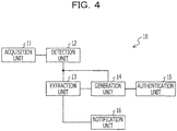
- FIG. 4 is a functional block diagram of a biometric authentication device according to an embodiment.
- This biometric authentication device 10 includes an acquisition unit 11, a detection unit 12, an extraction unit 13, a generation unit 14, an authentication unit 15, and a notification unit 16.
- the acquisition unit 11 photographs a biological part of an authenticated person while changing a relative position with respect to the biological part so as to acquire time-series biological images.
- the detection unit 12 detects pixels corresponding among the biological images from the time-series biological images which are acquired by the acquisition unit 11.
- the extraction unit 13 extracts a pixel of which a pixel value includes a surface reflection component from the biological part, from each of the time-series biological images which are acquired by the acquisition unit 11. This pixel extraction is performed on the basis of a degree of divergence of temporal variation of a pixel value of the pixel, which is detected by the detection unit 12, in time-series biological images from an estimation result of temporal variation of pixel values of all images constituting the time-series biological images.
- the generation unit 14 generates a biological image including no surface reflection from the biological part.
- This biological image is generated by correcting a pixel value of the extracted pixel which is extracted by the extraction unit 13 on the basis of a pixel value of a pixel corresponding to the extracted pixel, in each of the time-series biological images other than an extraction origin of the extracted pixel.
- the authentication unit 15 performs personal authentication of an authenticated person by using the biological image generated by the generation unit 14.
- the biometric authentication device 10 includes ten or more functional blocks.
- the notification unit 16 will be described later.
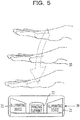
- FIG. 5 illustrates the configuration of an imaging device which is used when biometric authentication is performed by using a vein of a palm.
- An imaging device 20 repeatedly photographs a palm 30 while changing a relative position with respect to the palm 30, which is a biological part of an authenticated person, to acquire time-series biological images of the palm 30, and is an example of the acquisition unit 11 of FIG. 4 .
- An image of a vein of the palm 30 is reflected in the biological images.
- the imaging device 20 includes an illuminating device 21 and an imaging element 22.
- the illuminating device 21 irradiates the palm 30 with light for enough brightness for imaging by the imaging device 20.
- the imaging element 22 receives reflection light from the palm 30 and converts the reflection light to an electric signal indicating an image of the palm 30 so as to output the electric signal.
- an image of the palm 30 is picked up by this imaging device 20
- an authenticated person moves and monotonically brings the palm 30 closer to the imaging device 20 while holding the palm 30 over the imaging device 20.
- the imaging device 20 repeatedly images the palm 30 in a period in which a relative position with respect to the palm 30 changes, so as to obtain biological images.
- biological images obtained as described above include reflection light from the palm 30 due to the above-described surface reflection.
- a method of remove, which is performed by the biometric authentication device 10, of a surface reflection component from a biological image which is obtained by the imaging device 20 is now described.
- the brightness of the image region is mainly determined by brightness of an illumination and a relative position of a biological part with respect to the imaging device. Accordingly, if the brightness of the illumination and the relative position are same, the brightness of the image regions is approximately same even in different positions on the biological part.
- the brightness of the image region is prominently different in different positions on a biological part. The property of surface reflection components is described.
- FIGs. 6A and 6B are first described.
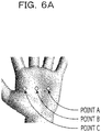
- FIG. 6A illustrates an example of focused pixels (focusing points) in a biological part which is reflected in a biological image.
- three focusing points in total which are point A, point B, and point C are set on illustrated positions on an image of a palm 30 which is acquired by the imaging device 20 of FIG. 5 .
- the detection unit 12 of FIG. 4 detects these focusing points from each of the time-series images of the palm 30 which are acquired by the imaging device 20 which is an example of the acquisition unit 11.
- Graphs illustrated in FIG. 6B represent pixel values, which are detected by the detection unit 12 from respective time-series images of the palm 30 which are acquired by the imaging device 20, of respective focusing points.
- a vertical axis represents a pixel value (brightness) and a horizontal axis represents photographing time of an image of the palm 30.
- same positions in the horizontal axis direction in these three graphs indicate that photographing time is same, that is, indicate that the relative position of the palm 30 with respect to the imaging device is same.
- a pixel value on the vertical axis of each of the graphs of FIG. 6B corresponds to intensity of reflection light from a focusing point.
- a part in which reflection light includes surface reflection components and a part in which reflection light includes only components independent from surface reflection are expressed by different types of hatching.
- photographing time at which a bump is generated in the graphs due to the inclusion of surface reflection components in reflection light is different among three focusing points.
- the main reason why photographing time at which surface reflection components are included is different among the focusing points is that directions of the illuminating device 21 and the imaging element 22 are different among respective focusing points of the palm 30.
- diffuse reflection components are not affected by directions, and diffuse reflection on a skin of the same person has an approximately same property irrespective of a part of the skin, so that change of diffuse reflection components is approximately uniform even if positions of focusing points are different from each other. Accordingly, if images which are obtained by continuously photographing a biological part are analyzed and a component exhibiting uniform brightness variation in the whole of the biological part irrespective of positions is extracted, the brightness variation may be considered as variation of diffuse reflection components.
- pixel values of the three focusing points in total which are the point A, the point B, and the point C are different according to biological features of respective focusing points (for example, existence of a vein under the skin and the like) even in photographing time at which only components independent from surface reflection components are included in reflection light.
- temporal variation rates of pixel values of these focusing points are approximately same as each other.
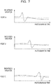
- FIG. 7 illustrates an example of pixel value temporal variation rates of respective focusing points in time-series images of the palm 30 which are acquired by the imaging device 20 by graphs, and the graphs of FIG. 7 are obtained by time-differentiating functions of the three graphs of FIG. 6B .
- all of the graphs have approximately-same curves of brightness variation (pixel value temporal variation rate) in a photographing time period in which only components independent from surface reflection are included in reflection light.
- the graphs of brightness variation of focusing points in a photographing time period in which surface reflection components are included in reflection light have shapes prominently different from graphs (only components independent from surface reflection is included in reflection light) of brightness variation of other focusing points in the same photographing time period.
- representative values of pixel value temporal variation rates of respective focusing points illustrated by these three graphs are calculated for every photographing time so as to estimate a pixel value temporal variation rate of the whole image of the palm 30.
- the method of this estimation is described with reference to FIG. 8 .
- FIG. 8 a graph [1] is obtained by superposing the graphs of FIG. 7 illustrating pixel value temporal variation rates of respective focusing points. Accordingly, three values (pixel value temporal variation rates) are illustrated in every photographing time of the graph.
- a representative value of a pixel value temporal variation rate of each focusing point for every photographing time is calculated so as to estimate a pixel value temporal variation rate of the whole image of the palm 30.
- a median value (median) of pixel value temporal variation rates of respective focusing points is calculated as the representative value.
- the graph [2] in FIG. 8 illustrates median values of pixel value temporal variation rates of respective focusing points for every photographing time, that is, illustrates an estimation result of a pixel value temporal variation rate of the whole image of the palm 30.
- This estimation result may be considered as illustration of a temporal variation rate of a pixel value which is obtained only from reflection light components independent from surface reflection (diffuse reflection components).
- a representative value of a pixel value temporal variation rate which is calculated in estimation of a pixel value temporal variation rate of the whole image of the palm 30 is not limited to a median value but may be an average value, for example.
- the estimation of a pixel value temporal variation rate of the whole image of the palm 30 is performed as described above.
- the estimation result, which is obtained as described above, of a pixel value temporal variation rate of the whole image of the palm 30 is compared to a pixel value temporal variation rate on a focusing point, being able to specify a period of photographing time in which surface reflection components are included in reflection light on the focusing point.
- This specifying method is described with reference to FIG. 9 .
- a graph of FIG. 9 is obtained by superposing the graph of the pixel value temporal variation rate of focusing point A in FIG. 7 on the graph [1] in FIG. 8 , that is, the graph of an estimation result of the pixel value temporal variation rate of the whole image of the palm 30.
- Such superposition of the two graphs clearly exhibits a period of photographing time in which there is divergence of the pixel value temporal variation rate of the focusing point A from the estimation result of the pixel value temporal variation rate of the whole image of the palm 30.
- This period is a period of photographing time in which a pixel value is affected by surface reflection components at the focusing point A.
- the extraction unit 13 of FIG. 4 extracts focusing points in a period of photographing time which is specified as described above and in which the pixel value is affected by surface reflection components, from each of time-series images of the palm 30 which are acquired by the imaging device 20 which is an example of the acquisition unit 11. Then, the generation unit 14 of FIG. 4 corrects the pixel value of the focusing point, which is extracted by the extraction unit 13 as described above, so as to generate an image of the palm including no surface reflection components.
- the correction is performed by interpolating a pixel value of a focusing point of an image of the palm 30 of an extraction origin of the extracted focusing point at photographing time on the basis of a corresponding relationship between photographing time and a pixel value of the focusing point, in each of time-series biological images except for an extraction origin of an extracted focusing point.
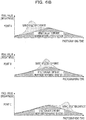
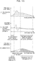
- a graph [1] is a graph of the focusing point A among the graphs representing pixel values of respective focusing points and illustrated in FIG. 6B , and a graph [2] is same as the graph of FIG. 9 .
- a graph [3] is a graph representing a pixel value after correction of the pixel value of the graph [1] is performed.
- the graph [1] of the focusing point A is separated into a period of photographing time in which a pixel value is affected by surface reflection components and a period of photographing time in which the pixel value is not affected by surface reflection components, on the basis of a degree of divergence between superposed graphs of the graph [2].
- the pixel value of the graph [1] is not affected by surface reflection components in a period of photographing time in which divergence of a pixel value temporal variation rate of the focusing point A from an estimation result of a pixel value temporal variation rate of the whole image of the palm 30 is small (less than a predetermined threshold value). Accordingly, a pixel value is not corrected in this period which is hatched in the graph [3].
- the pixel value of the graph [1] is affected by surface reflection components in a period of photographing time in which divergence of the pixel value temporal variation rate of the focusing point A from the estimation result of the pixel value temporal variation rate of the whole image of the palm 30 is large (equal to or above the predetermined threshold value). Accordingly, a pixel value is corrected in this period which is not hatched in the graph [3].
- a pixel value of a focusing point in an image, which is photographed during this period, of the palm 30 corresponding to photographing time is linearly interpolated on the basis of a relationship between photographing time and a pixel value of the focusing point in images of the palm 30 which are taken immediately before and after the period, in this embodiment.
- This linear interpolation of a pixel value of a focusing point is performed by calculating the following formula, for example.
- X new (t a ) denotes a luminance value after interpolation, at time t a .
- X(t) denotes a luminance value at time t
- M(t) denotes an estimation result of a pixel value temporal variation rate of the whole image of the palm 30 at time t.
- Time t b and time t e are respectively photographing time immediately before and after correction of a pixel value.
- Correction of a pixel value does not have to be performed with respect to all images which are taken during a photographing period in which a pixel value is affected by surface reflection components. That is, the above-described correction may be performed only to an image which is taken at an optimum distance for biometric authentication, or an image to be corrected, such as an image which is thinned at a predetermined time interval, may be selected in view of time and accuracy for an execution of biometric authentication.
- the generation unit 14 generates an image of the palm 30 from which surface reflection components are removed as described above.
- the authentication unit 15 performs personal identification of an authenticated person by using an image of the palm 30 which is generated as described above, being able to perform highly-accurate authentication.
- the biometric authentication device 10 of FIG. 4 photographs a moving biological part
- the biometric authentication device 10 corrects a surface reflection component included in each point by using a property that a rate of a surface reflection component on each point of the biological part continuously varies, thus generating a biological image including no surface reflection component. Then, the biometric authentication device 10 performs personal identification of an authenticated person by using the biological image which is generated as described above.
- the biometric authentication device 10 of FIG. 4 further includes the notification unit 16.
- the notification unit 16 notifies an authenticated person of an execution of re-imaging of a biological image.
- the notification is performed when the degree of divergence of temporal variation of a pixel value of a pixel, which is detected by the detection unit 12, in time-series biological images from an estimation result of temporal variation of a pixel value in all pixels constituting the time-series biological images is smaller than a predetermined threshold value in all pixels.
- the notification unit 16 performs the above-described notification to request an authenticated person for an execution of re-imaging, enabling re-imaging of a biological image and generation of a biological image including no surface reflection components.
- FIG. 11 is a detailed functional block diagram of the biometric authentication device 10 of the embodiment.
- a continuous image photographing unit 31 and a continuous image storage unit 32 are included in the acquisition unit 11 of FIG. 4 .
- an image tracking normalization unit 33 is included in the detection unit 12 of FIG. 4 .
- a pixel value variation rate calculation unit 34 and a diffuse reflection component variation rate estimation unit 36 are included in the extraction unit 13 of FIG. 4 .
- a guide message output unit 35 is included in the notification unit 16 of FIG. 4 .
- a correction range calculation unit 37, a pixel value correction unit 38, and a correction image storage unit 39 are included in the generation unit 14 of FIG. 4 .
- a biometric authentication unit 40 and an authentication result output unit 41 are included in the authentication unit 15 of FIG. 4 .
- the continuous image photographing unit 31 continuously photographs a moving biological part of an authenticated person so as to acquire time-series biological images.
- the imaging device 20 of FIG. 5 serves as the continuous image photographing unit 31.
- the continuous image storage unit 32 is an image memory which stores the time-series biological images which are obtained by the photographing of the continuous image photographing unit 31.
- the image tracking normalization unit 33 detects a plurality of pixels (above-described focusing points), which correspond among the biological images, of an image of a biological part from the time-series biological images stored in the continuous image storage unit 32 and tracks the pixels. Further, the image tracking normalization unit 33 performs image conversion (normalization) illustrated in FIG. 12 . This normalization is image conversion in which biological images are expanded and moved so as to place respective corresponding focusing points on the same positions among the biological images.
- the image tracking normalization unit 33 may calculate positional information, on respective biological images, of corresponding focusing points instead of actually performing image conversion, so as to express a corresponding relationship of the focusing points by using the positional information.
- the pixel value variation rate calculation unit 34 calculates a temporal variation rate of a pixel value of each of the focusing points of the time-series biological images which are normalized by the image tracking normalization unit 33.
- the guide message output unit 35 outputs a message (notification) to an authenticated person to guide the authenticated person to move a biological part for re-imaging of a biological image when the temporal variation rate of the pixel value which is obtained by the pixel value variation rate calculation unit 34 is small enough not to reach a predetermined threshold value.
- the diffuse reflection component variation rate estimation unit 36 estimates a temporal variation rate of a pixel value of the whole image of the biological part, on the basis of the temporal variation rate of the pixel value which is calculated for each of the focusing points in the pixel value variation rate calculation unit 34. As described above, this estimation result may be considered that the estimation result expresses a temporal variation rate of a pixel value mainly including diffuse reflection components from a biological part.
- the correction range calculation unit 37 compares the temporal variation rate, which is estimated in the diffuse reflection component variation rate estimation unit 36, of the pixel value of the whole image of the biological part with a pixel value variation rate of a focusing point of each of the biological images so as to calculate a range of photographing time in which the difference between the temporal variation rate and the pixel value variation rate is not within a range of a predetermined threshold value.
- This range of photographing time which is calculated by the correction range calculation unit 37 is set as a range of photographing time in which correction of a pixel value is performed on the focusing point.
- the pixel value correction unit 38 corrects a pixel value within the range, which is obtained in the correction range calculation unit 37, of photographing time in which correction of a pixel value is performed to a pixel value including no surface reflection components from a biological part, for each of the focusing points.
- the correction image storage unit 39 stores a biological image which is generated by correcting a pixel value of each focusing point by the pixel value correction unit 38 and includes no surface reflection from a biological part.
- the correction image storage unit 39 stores information of the number of corrected focusing points, the variation amount of a pixel value which is changed by the correction, and the like in a manner to associate the information with the generated biological image.
- the biometric authentication unit 40 performs personal identification of an authenticated person on the basis of biometric authentication in which a corrected biological image which is read from the correction image storage unit 39 is compared and collated with preliminarily-registered biological information of the authenticated person.
- the biometric authentication unit 40 may use a plurality of corrected biological images which are stored in the correction image storage unit 39 for biometric authentication with no priority level. Further, the biometric authentication unit 40 may grant using priority in biometric authentication of corrected biological images, on the basis of the information such as the number of corrected focusing points and the variation amount of a pixel value changed by the correction, which are stored in the correction image storage unit 39.
- the authentication result output unit 41 outputs a result of personal identification performed by the biometric authentication unit 40.
- the biometric authentication device 10 of FIG. 11 is configured as described above. Here, part of constituent elements of the biometric authentication device 10 illustrated in FIGs. 4 and 11 may be composed of a computer having the standard configuration.
- FIG. 13 illustrates an example of the configuration of a computer.
- This computer 50 includes a micro processing unit (MPU) 51, a read only memory (ROM) 52, a random access memory (RAM) 53, a hard disk device 54, an input device 55, a display device 56, an interface device 57, and a storage medium driving device 58.
- MPU micro processing unit
- ROM read only memory
- RAM random access memory
- hard disk device 54 a hard disk device 54
- an input device 55 a display device 56
- an interface device 57 an interface device 57
- storage medium driving device 58 storage medium driving device
- the MPU 51 is an arithmetic processing device which controls the whole operation of the computer 50.
- the ROM 52 is a read only semiconductor memory in which a predetermined basic control program is preliminarily stored.
- the MPU 51 reads and executes the basic control program at activation of the computer 50, being able to control operations of respective constituent elements of the computer 50.
- the RAM 53 is an occasionally-writable and readable semiconductor memory which may be used as an operation storage region when the MPU 51 executes various types of control programs.
- the hard disk device 54 is a storage device to store various types of control programs which are executed by the MPU 51 and various types of data.
- the MPU 51 reads and executes a predetermined control program which is stored in the hard disk device 54, being able to perform various types of control processing.
- the input device 55 is a keyboard device or a mouse device, for example.
- the input device 55 When the input device 55 is operated by an administrator of the biometric authentication device 10, for example, the input device 55 acquires input of various information, which corresponds to the operation content, from the administrator and transmits acquired input information to the MPU 51.
- the display device 56 is a liquid crystal display, for example, and displays various texts and images in accordance with display data which is transmitted from the MPU 51.
- the interface device 57 administrates transmission and reception of various information among various devices which are connected to the computer 50.
- the storage medium driving device 58 reads various types of control programs and data which are stored in a portable storage medium 60.
- the MPU 51 may perform various types of control processing described later by reading and executing a predetermined control program which is stored in the portable storage medium 60 via the storage medium driving device 58.
- Examples of the portable storage medium 60 include a compact disc read only memory (CD-ROM), a digital versatile disc read only memory (DVD-ROM), and a flash memory provided with a connector of the universal serial bus (USB) standard.
- a control program to allow the MPU 51 to perform later-described control processing is generated, for example.
- the generated control program is preliminarily stored in the hard disk device 54 or the portable storage medium 60.
- the hard disk device 54 is set to serve as the continuous image storage unit 32 and the correction image storage unit 39, for example.
- the imaging device 20 of FIG. 5 which is an example of the continuous image photographing unit 31 (that is, the acquisition unit 11) is connected to the interface device 57 of the computer 50 so that the computer 50 may take in biological images by controlling the imaging device 20 to allow the imaging device 20 to acquire the biological images.
- a predetermined instruction is given to the MPU 51 so as to allow the MPU 51 to read and execute the control program.
- the computer 50 may provide the functions of respective functional blocks of the biometric authentication device 10.
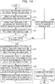
- FIG. 14 is a flowchart illustrating processing contents of the control processing.
- the continuous image photographing unit 31 first performs processing in which the continuous image photographing unit 31 continuously photographs a biological part of an authenticated person while changing a relative position with respect to the biological part and acquires time-series biological images so as to store the acquired biological images in the continuous image storage unit 32, in S101.
- the relative position with respect to the biological part of the authenticated person is changed by moving the biological part of the authenticated person.
- the image tracking normalization unit 33 performs processing in which the image tracking normalization unit 33 detects a plurality of focusing points, which correspond among the biological images, on an image of the biological part from the time-series biological images stored in the continuous image storage unit 32 and tracks the focusing points, in S102.
- the image tracking normalization unit 33 performs image normalization conversion processing so as to place the corresponding focusing points respectively on the same positions among the biological images, in S103.
- the pixel value variation rate calculation unit 34 performs processing in which the pixel value variation rate calculation unit 34 calculates a pixel value of each of the focusing points from the time-series biological images and calculates a pixel value temporal variation rate V(n, t) of a focusing point n at photographing time t for each of the focusing points on the basis of the obtained pixel value and photographing time of the biological image, in S104.
- the pixel value variation rate calculation unit 34 performs processing of determining whether the pixel value temporal variation rate V(n, t) obtained by the processing of S104 is smaller than a predetermined first threshold value on an arbitrary focusing point n at arbitrary photographing time t, in S105.
- the processing goes to S106.
- the processing goes to S107.
- the guide message output unit 35 performs processing of outputting a message (notification) to guide the authenticated person to move the biological part for re-imaging of biological images. Subsequently, the guide message output unit 35 returns the processing to S101 and then, the above-described processing is executed again.
- the diffuse reflection component variation rate estimation unit 36 performs processing of calculating a representative value M(t) of the pixel value temporal variation rates V(n, t) on predetermined number (M pieces) of focusing points at every photographing time t of the time-series biological images.
- a median value or an average value of pixel value temporal variation rates V(n, t) of M pieces of focusing points is employed as the representative value, as described above.
- the representative value M(t) obtained by this processing is an estimation result of the pixel value temporal variation rate of the whole image of the biological part.
- the correction range calculation unit 37 performs processing of calculating a range of photographing time t in which an absolute value of V(n, t)-M(t) is larger than a predetermined second threshold value on each of detected focusing points.
- Ranges of photographing time t which are obtained at respective focusing points by this processing become periods in which correction with respect to pixel values of respective focusing points is performed.
- t b (n) and ending time of the range is denoted as t e (n).
- the pixel value correction unit 38 performs processing of correcting a pixel value within the period obtained in the processing of S108 for each of the focusing points.
- corrected luminance value X new (t a (n)) on the focusing point n at time t a (n) within the period obtained in the processing of S108 is calculated by performing calculation of the above-mentioned Formula 1.
- an estimation result of the pixel value temporal variation rate of the whole image of the biological part which is obtained in the processing of S107 is assigned to M(t) in Formula 1.
- the pixel value correction unit 38 performs processing in which the pixel value correction unit 38 generates a biological image including no surface reflection from the biological part on the basis of the luminance value corrected in the processing of S109 and stores the biological image in the correction image storage unit 39.
- processing a plurality of biological images including no surface reflection from the biological part is stored in the correction image storage unit 39 in time series.
- the pixel value correction unit 38 stores not only the biological image including no surface reflection from the biological part but also respective information of photographing time, the number of corrected focusing points, and the variation amount of a pixel value which is changed by the correction, in the correction image storage unit 39 in a manner to associate the information with the biological image.
- the biometric authentication unit 40 performs authentication processing in which personal identification of a certain authenticated person is performed by biometric authentication in which a corrected biological image read from the correction image storage unit 39 is compared and collated with preliminarily-registered biological information of the certain authenticated person.
- biometric authentication in which a corrected biological image read from the correction image storage unit 39 is compared and collated with preliminarily-registered biological information of the certain authenticated person.
- the authentication result output unit 41 performs processing of outputting a result of the personal identification by the authentication processing of Sill. Then, the control processing of FIG. 14 is ended. The processing contents of the authentication processing of S111 in the control processing of FIG. 14 are now described.
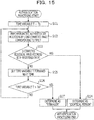
- FIG. 15 is a flowchart illustrating processing contents of a first example of the authentication processing.
- the biometric authentication unit 40 compares and collates each of a plurality of biological images which are stored in the correction image storage unit 39 and include no surface reflection from a biological part with registered biological information of an authenticated person (above-described registered biological information).
- the biometric authentication unit 40 identifies the authenticated person.
- the biometric authentication unit 40 first performs processing of assigning an initial value Ts to time variable T for specifying photographing time, in S121.
- this initial value Ts starting time of continuous photographing of a biological part performed by the continuous image photographing unit 31 is set.
- the biometric authentication unit 40 performs biometric authentication processing in which the biometric authentication unit 40 reads out a biological image at photographing time T from the correction image storage unit 39 among the plurality of biological images which are stored in the correction image storage unit 39 and include no surface reflection from the biological part, and compares and collates the read-out biological image with the registered biological information.
- the biometric authentication unit 40 performs processing of determining whether the biological image read out from the correction image storage unit 39 is accorded with the registered biological information (whether the degree of similarity of the read-out biological image and the registered biological information is larger than a predetermined threshold value) as a result of the biometric authentication processing of S122.
- the biometric authentication unit 40 determines that the read-out biological image and the registered biological information are accorded with each other (when the determination result is Yes)
- the biometric authentication unit 40 performs processing of determining that the authenticated person is identified in S124 and then ends the authentication processing.
- the biometric authentication unit 40 determines that the read-out biological image and the registered biological information are not accorded with each other (when the determination result is No) the processing goes to S125.
- the biometric authentication unit 40 performs processing in which the biometric authentication unit 40 changes the above-described value of the time variable T so as to set forward from the currently-set photographing time to next photographing time of a biological image. Then, in S126, the biometric authentication unit 40 performs processing of determining whether the value of the time variable T exceeds ending time Te of the continuous photographing of the biological part performed by the continuous image photographing unit 31. When the biometric authentication unit 40 determines that the value of the time variable T exceeds the ending time Te (when the determination result is Yes), the biometric authentication unit 40 performs processing of providing a determination result that the authenticated person is a stranger, in S127 and then ends this authentication processing. On the other hand, when the biometric authentication unit 40 determines that the value of the time variable T does not exceed the ending time Te (when the determination result is No), the biometric authentication unit 40 returns the processing to S122 and then executes the above-described processing again.
- FIG. 16 is a flowchart illustrating processing contents of a second example of the authentication processing.
- the biometric authentication unit 40 compares and collates each of a plurality of biological images which are stored in the correction image storage unit 39 and include no surface reflection from a biological part with registered biological information, as is the case with the first example.
- the biometric authentication unit 40 compares and collates biological images read out from the correction image storage unit 39 with the registered biological information in an order of images having smaller correction, more specifically, an order of images with smaller number of focusing points at which a pixel value is corrected.
- the biometric authentication unit 40 When the processing of FIG. 16 is started, the biometric authentication unit 40 first performs processing of setting an initial value of time variable T for specifying photographing time in S141.
- photographing time of a biological image having the smallest number of focusing points at which correction is performed is set to be time variable T as the initial value.
- information of the number of focusing points subject to the correction is stored in the correction image storage unit 39 in a manner to be associated with biological images, by the processing of S110 of FIG. 14 described above.
- the biometric authentication unit 40 refers to this information so as to set the time variable T to photographing time of a biological image having the smallest number of focusing points subject to the correction, as the initial value.
- the biometric authentication unit 40 performs biometric authentication processing in which the biometric authentication unit 40 reads out a biological image at photographing time T from the correction image storage unit 39 among the plurality of biological images which are stored in the correction image storage unit 39 and include no surface reflection from the biological part, and compares and collates the read-out biological image with the registered biological information.
- the biometric authentication unit 40 performs processing of determining whether the biological image read out from the correction image storage unit 39 is accorded with the registered biological information (whether the degree of similarity of the read-out biological image and the registered biological information is larger than a predetermined threshold value) as a result of the biometric authentication processing of S142.
- the biometric authentication unit 40 determines that the read-out biological image and the registered biological information are accorded with each other (when the determination result is Yes)
- the biometric authentication unit 40 performs processing of providing a determination result that the authenticated person is identified, in S144 and then ends the authentication processing.
- the biometric authentication unit 40 determines that the read-out biological image and the registered biological information are not accorded with each other (when the determination result is No)
- the processing goes to S145.
- the biometric authentication unit 40 performs processing in which the biometric authentication unit 40 changes the above-described value of the time variable T so as to set forward to photographing time of a biological image of which the number of focusing points subject to the correction is the second smallest to that of the biological image at the photographing time which is currently set as the time variable T.
- the biometric authenticated unit 40 performs processing of determining whether the biometric authentication processing of S142 is performed by using all biological images of which photographing time is in a period from the starting time Ts of the continuous photographing of the biological part performed by the continuous image photographing unit 31 to the ending time Te of the continuous photographing.
- the biometric authentication unit 40 determines that the biometric authentication processing is performed by using the all biological images (when the determination result is Yes)
- the biometric authentication unit 40 performs processing of providing a determination result that the authenticated person is a stranger, in S147 and then ends the authentication processing.
- the biometric authentication unit 40 determines that there still are biological images which have not been used for the biometric authentication processing in the correction image storage unit 39 (when the determination result is No)
- the biometric authentication unit 40 returns the processing to S142 and then executes the above-described processing again.
- the processing described thus far is the second example of the authentication processing.
- FIG. 17 is a flowchart illustrating processing contents of a third example of the authentication processing.
- the biometric authentication unit 40 compares and collates each of a plurality of biological images which are stored in the correction image storage unit 39 and include no surface reflection from a biological part with registered biological information, as is the case with the first example.
- the biometric authentication unit 40 compares and collates biological images read out from the correction image storage unit 39 with the registered biological information in an order of images having smaller correction, more specifically, an order of images in which a sum of difference between pixel values of before and after correction in respective focusing points subject to the correction is smaller.
- the biometric authentication unit 40 first performs processing of setting an initial value of time variable T for specifying photographing time, in S161.
- photographing time of a biological image having the smallest correction amount of pixel values is set to be time variable T as the initial value.
- the correction amount of pixel values of a biological image is obtained by calculating a sum of absolute values of difference between values before and after the correction of pixel values subject to the correction, on all focusing points, at which the correction is performed, of the biological image subject.
- the biometric authentication unit 40 calculates correction amounts of the pixel values of respective biological images by using this information so as to set the time variable T to photographing time of a biological image of which the correction amount of pixel values is the smallest, as the initial value.
- the biometric authentication unit 40 performs biometric authentication processing in which the biometric authentication unit 40 reads out a biological image at the photographing time T from the correction image storage unit 39 among the plurality of biological images which are stored in the correction image storage unit 39 and include no surface reflection from the biological part, and compares and collates the read-out biological image with the registered biological information.
- the biometric authentication unit 40 performs processing of determining whether the biological image read out from the correction image storage unit 39 is accorded with the registered biological information (whether the degree of similarity between the read-out biological image and the registered biological information is larger than a predetermined threshold value) as a result of the biometric authentication processing of S162.
- the biometric authentication unit 40 determines that the read-out biological image and the registered biological information are accorded with each other (when the determination result is Yes)
- the biometric authentication unit 40 performs processing of providing a determination result that the authenticated person is identified, in S164 and then ends the authentication processing.
- the biometric authentication unit 40 determines that the read-out biological image and the registered biological information are not accorded with each other (when the determination result is No)
- the processing goes to S165.
- the biometric authentication unit 40 performs processing in which the biometric authentication unit 40 changes the above-described value of the time variable T so as to set forward to photographing time of a biological image of which the correction amount of pixel values is the second smallest to that of a biological image at photographing time which is currently set as the time variable T.
- the biometric authenticated unit 40 performs processing of determining whether the biometric authentication processing of S162 is performed by using all biological images of which photographing time is in a period from the starting time Ts of the continuous photographing of the biological part performed by the continuous image photographing unit 31 to the ending time Te of the continuous photographing.
- the biometric authentication unit 40 determines that the biometric authentication processing is performed by using the all biological images (when the determination result is Yes)
- the biometric authentication unit 40 performs processing of providing a determination result that the authenticated person is a stranger, in S167 and then ends the authentication processing.
- the biometric authentication unit 40 determines that there still are biological images which have not been used for the biometric authentication processing in the correction image storage unit 39 (when the determination result is No), the biometric authentication unit 40 returns the processing to S162 and then executes the above-described processing again.
- the biometric authentication device 10 may perform biometric authentication while removing an effect caused by surface reflection components included in reflection light at a biological part.
- the biometric authentication device 10 may estimate a pixel value temporal variation rate of the whole image of a biological part by using a distance sensor which detects the distance between the imaging device 20 and a photographing object.
Claims (11)
- Biometrische Authentifizierungsvorrichtung, umfassend:eine Erfassungseinheit (31), die konfiguriert ist, um Zeitreihen biologischer Bilder, die ein Venenmuster einschließen, durch wiederholtes Abbilden eines biologischen Teils einer Person in einer Zeitspanne zu erfassen, in der eine relative Position in Bezug auf den biologischen Teil geändert wird;eine Detektionseinheit (33), die konfiguriert ist, um eine Vielzahl von Fokussierungspunkten in jedem von mindestens einem Teil der Zeitreihe biologischer Bilder zu detektieren, wobei die Vielzahl von Fokussierungspunkten voreingestellte Punkte auf einem Bild des biologischen Teils sind, die innerhalb der Zeitreihe biologischer Bilder korrespondieren;eine Berechnungseinheit (34, 36, 37), die konfiguriert ist, um für jeden der Vielzahl von Fokussierungspunkten einen ersten Zeitbereich zu berechnen, der eine Zeitspanne ist, in der ein Divergenzgrad zwischen einer ersten zeitlichen Variation und einer zweiten zeitlichen Variation größer ist als ein Schwellenwert, zum Bewerten, ob ein Fokussierungspunkt des jeweiligen der Vielzahl von Fokussierungspunkten von Blendung betroffen ist, wobei die erste zeitliche Variation eine zeitliche Variation von Helligkeit in Bezug auf Pixel ist, die dem jeweiligen der Vielzahl von Fokussierungspunkten entsprechen, die von jedem aus dem mindestens einen Teil der Zeitreihe biologischer Bilder detektiert werden, wobei die zweite zeitliche Variation eine zeitliche Variation von Helligkeit in Bezug auf Pixel ist, die einem Gesamtbild von jedem aus dem mindestens einen Teil der Zeitreihe biologischer Bilder entsprechen;eine Erzeugungseinheit, die konfiguriert ist, um ein biologisches Bild durch Korrigieren eines ersten Pixelwerts, der einem Fokussierungspunkt der Vielzahl von Fokussierungspunkten innerhalb des ersten Zeitbereichs entspricht, auf der Grundlage eines zweiten Pixelwerts, der dem Fokussierungspunkt außerhalb des ersten Zeitbereichs entspricht, zu erzeugen; undeine Authentifizierungseinheit (40), die konfiguriert ist, um persönliche Authentifizierung der Person durch Verwenden des biologischen Bilds, das erzeugt wird, durchzuführen.
- Vorrichtung nach Anspruch 1, wobei die Erzeugungseinheit den ersten Pixelwert durch Interpolieren des ersten Pixelwerts auf der Grundlage einer Beziehung zwischen einem Zeitpunkt außerhalb des ersten Zeitbereichs und dem zweiten Pixelwert korrigiert.
- Vorrichtung nach Anspruch 1, weiter umfassend:
eine Benachrichtigungseinheit, die konfiguriert ist, um die authentifizierte Person über eine Ausführung einer Neuabbildung des biologischen Bilds in einem Fall zu benachrichtigen, in dem der Divergenzgrad zwischen der ersten zeitlichen Variation und der zweiten zeitlichen Variation niedriger ist als ein vorbestimmter Schwellenwert. - Vorrichtung nach Anspruch 1,
wobei die Erzeugungseinheit eine Vielzahl von korrigierten biologischen Bildern von dem biologischen Teil der Zeitreihe biologischer Bilder erzeugt, und
wobei die Authentifizierungseinheit Authentifizierung zwischen jedem der Vielzahl von biologischen Bildern, die erzeugt werden, und einem registrierten biologischen Bild, wobei das registrierte biologische Bild zuvor registriert wird, der authentifizierten Person durchführt und die authentifizierte Person als eine identische Person in einem Fall identifiziert, in dem die Authentifizierungseinheit bei Authentifizierung in Bezug auf mindestens eines der Vielzahl von biologischen Bildern, die erzeugt werden, erfolgreich ist. - Vorrichtung nach Anspruch 4, wobei die Authentifizierungseinheit die persönliche Authentifizierung durch Verwenden der Vielzahl von biologischen Bildern, die erzeugt werden, in einer Reihenfolge von biologischen Bildern, die eine niedrigere Anzahl von Pixeln aufweisen, die der Korrektur unterliegen, durchführt.
- Vorrichtung nach Anspruch 4, wobei die Authentifizierungseinheit eine Summe von Absolutwerten von Unterschieden zwischen Pixelwerten von jeweiligen Pixeln vor und nach Korrektur bestimmt und die persönliche Authentifizierung durch Verwenden der Vielzahl von biologischen Bildern, die erzeugt werden, in einer Reihenfolge von biologischen Bildern, die eine niedrigere Summe der Absolutwerte der Unterschiede aufweisen, durchführt.
- Biometrisches Authentifizierungsverfahren, umfassend:Erfassen von Zeitreihen biologischer Bilder, die ein Venenmuster einschließen, durch wiederholtes Abbilden eines biologischen Teils einer Person in einer Zeitspanne, in der eine relative Position in Bezug auf den biologischen Teil geändert wird;Detektieren einer Vielzahl von Fokussierungspunkten in jedem von mindestens einem Teil der Zeitreihe biologischer Bilder, wobei die Vielzahl von Fokussierungspunkten voreingestellte Punkte auf einem Bild des biologischen Teils sind, die innerhalb der Zeitreihe biologischer Bilder korrespondieren;Berechnen eines ersten Zeitbereichs für jeden der Vielzahl von Fokussierungspunkten, der eine Zeitspanne ist, in der ein Divergenzgrad zwischen einer ersten zeitlichen Variation und einer zweiten zeitlichen Variation größer ist als ein Schwellenwert zum Bewerten, ob ein Fokussierungspunkt des jeweiligen der Vielzahl von Fokussierungspunkten von Blendung betroffen ist, wobei die erste zeitliche Variation eine zeitliche Variation von Helligkeit in Bezug auf Pixel ist, die dem jeweiligen der Vielzahl von Fokussierungspunkten entsprechen, die von jedem des mindestens einen Teils der Zeitreihe von biologischen Bildern detektiert werden, wobei die zweite zeitliche Variation eine zeitliche Variation von Helligkeit in Bezug auf Pixel ist, die einem Gesamtbild von jedem des mindestens einen Teils der Zeitreihe biologischer Bilder entsprechen;Erzeugen eines biologischen Bilds durch einen Computerprozessor durch Korrigieren eines ersten Pixelwerts, der einem Fokussierungspunkt der Vielzahl von Fokussierungspunkten innerhalb des ersten Zeitbereichs entspricht, auf der Grundlage eines zweiten Pixelwerts, der dem Fokussierungspunkt außerhalb des ersten Zeitbereichs entspricht; undDurchführen persönlicher Authentifizierung der Person durch Verwenden des biologischen Bilds, das erzeugt wird.
- Verfahren nach Anspruch 7, wobei bei dem Erzeugen der erste Pixelwert durch Interpolieren des ersten Pixelwerts auf der Grundlage einer Beziehung zwischen einem Zeitpunkt außerhalb des ersten Zeitbereichs und dem zweiten Pixelwert korrigiert wird.
- Verfahren nach Anspruch 7, weiter umfassend:
Benachrichtigen der authentifizierten Person über eine Ausführung einer Neuabbildung des biologischen Bilds in einem Fall, in dem der Divergenzgrad zwischen der ersten zeitlichen Variation und der zweiten zeitlichen Variation niedriger ist als ein vorbestimmter Schwellenwert. - Verfahren nach Anspruch 7,
wobei bei der Erzeugung eine Vielzahl von korrigierten biologischen Bildern von dem biologischen Teil aus der Zeitreihe biologischer Bilder erzeugt wird, und
wobei bei dem Durchführen von persönlicher Authentifizierung Authentifizierung zwischen jedem der Vielzahl biologischer Bilder, die erzeugt werden, und einem registrierten biologischen Bild, wobei das registrierte biologische Bild zuvor registriert wird, der authentifizierten Person durchgeführt wird und die authentifizierte Person als eine identische Person in einem Fall identifiziert wird, in dem Authentifizierung in Bezug auf mindestens eines der Vielzahl von biologischen Bildern, die erzeugt werden, erfolgreich ist. - Verfahren nach Anspruch 10, wobei bei dem Durchführen von persönlicher Authentifizierung die persönliche Authentifizierung durch Verwenden der Vielzahl von biologischen Bildern, die erzeugt werden, in einer Reihenfolge von biologischen Bildern, die eine niedrigere Anzahl von Pixeln aufweisen, die der Korrektur unterliegen, durchgeführt wird.
Applications Claiming Priority (1)
| Application Number | Priority Date | Filing Date | Title |
|---|---|---|---|
| JP2011180902A JP5780053B2 (ja) | 2011-08-22 | 2011-08-22 | 生体認証装置、生体認証方法、及びプログラム |
Publications (3)
| Publication Number | Publication Date |
|---|---|
| EP2562687A2 EP2562687A2 (de) | 2013-02-27 |
| EP2562687A3 EP2562687A3 (de) | 2017-11-22 |
| EP2562687B1 true EP2562687B1 (de) | 2020-01-15 |
Family
ID=46581742
Family Applications (1)
| Application Number | Title | Priority Date | Filing Date |
|---|---|---|---|
| EP12174925.3A Active EP2562687B1 (de) | 2011-08-22 | 2012-07-04 | Vorrichtung und Verfahren zur biometrischen Authentifizierung |
Country Status (3)
| Country | Link |
|---|---|
| US (1) | US8855378B2 (de) |
| EP (1) | EP2562687B1 (de) |
| JP (1) | JP5780053B2 (de) |
Families Citing this family (11)
| Publication number | Priority date | Publication date | Assignee | Title |
|---|---|---|---|---|
| JP5747916B2 (ja) * | 2010-07-29 | 2015-07-15 | 富士通株式会社 | 生体認証装置および生体認証プログラム |
| US9823352B2 (en) * | 2014-10-31 | 2017-11-21 | Rockwell Automation Safety Ag | Absolute distance measurement for time-of-flight sensors |
| US20180325427A1 (en) * | 2015-11-16 | 2018-11-15 | Sharp Kabushiki Kaisha | Imaging device, biometric authentication device, and semiconductor laser |
| JPWO2017115512A1 (ja) * | 2015-12-28 | 2018-09-20 | シャープ株式会社 | 撮像装置及び生体認証装置 |
| JP6743429B2 (ja) * | 2016-03-11 | 2020-08-19 | 富士通株式会社 | 生体撮影装置、生体撮影方法および生体撮影プログラム |
| US10536464B2 (en) * | 2016-06-22 | 2020-01-14 | Intel Corporation | Secure and smart login engine |
| EP3264321A1 (de) * | 2016-06-29 | 2018-01-03 | Rainer Philippeit | Verfahren und vorrichtung zur berührungslosen erfassung einer venenstruktur eines körperteils |
| US10423768B2 (en) * | 2016-07-27 | 2019-09-24 | Google Llc | Real-time user authentication using integrated biometric sensor |
| KR20180046679A (ko) * | 2016-10-28 | 2018-05-09 | 삼성전자주식회사 | 지문 인식 방법 및 이를 포함하는 전자 기기 |
| CN106570489A (zh) * | 2016-11-10 | 2017-04-19 | 腾讯科技(深圳)有限公司 | 活体判别方法和装置、身份认证方法和装置 |
| KR102434703B1 (ko) * | 2017-08-14 | 2022-08-22 | 삼성전자주식회사 | 생체 이미지 처리 방법 및 이를 포함한 장치 |
Family Cites Families (22)
| Publication number | Priority date | Publication date | Assignee | Title |
|---|---|---|---|---|
| JPH10162146A (ja) | 1996-11-29 | 1998-06-19 | Oki Electric Ind Co Ltd | 個人識別装置 |
| US6587581B1 (en) * | 1997-01-10 | 2003-07-01 | Hitachi, Ltd. | Visual inspection method and apparatus therefor |
| US6639594B2 (en) * | 2001-06-03 | 2003-10-28 | Microsoft Corporation | View-dependent image synthesis |
| KR100954640B1 (ko) | 2002-02-05 | 2010-04-27 | 파나소닉 주식회사 | 개인인증방법 및 개인인증장치 |
| JP3586456B2 (ja) | 2002-02-05 | 2004-11-10 | 松下電器産業株式会社 | 個人認証方法および個人認証装置 |
| JP4499341B2 (ja) | 2002-05-09 | 2010-07-07 | ソニー株式会社 | 生体認証装置及び生体認証方法 |
| CN1662931A (zh) | 2002-05-09 | 2005-08-31 | 索尼株式会社 | 活组织模式检测方法、活组织模式检测设备、生物统计学认证方法和生物统计学认证设备 |
| GB0217570D0 (en) * | 2002-07-30 | 2002-09-11 | Univ Birmingham | Method and apparatus for quantifying material or object properties |
| JP4258393B2 (ja) * | 2003-03-13 | 2009-04-30 | 三菱電機株式会社 | 個人識別装置および指紋画像撮像装置、指紋画像取得方法 |
| WO2006073450A2 (en) * | 2004-04-27 | 2006-07-13 | The Trustees Of The University Of Pennsylvania | Polarization and reflection based non-contact latent fingerprint imaging and lifting |
| JP2005353014A (ja) * | 2004-05-14 | 2005-12-22 | Sony Corp | 撮像装置 |
| US20050276508A1 (en) * | 2004-06-15 | 2005-12-15 | Lockheed Martin Corporation | Methods and systems for reducing optical noise |
| JP3935499B2 (ja) * | 2004-07-26 | 2007-06-20 | 松下電器産業株式会社 | 画像処理方法、画像処理装置および画像処理プログラム |
| KR100647298B1 (ko) * | 2004-11-29 | 2006-11-23 | 삼성전자주식회사 | 빛 반사를 고려한 영상 처리 장치와 방법 및 컴퓨터프로그램을 저장하는 컴퓨터로 읽을 수 있는 기록매체 |
| JP4459137B2 (ja) * | 2005-09-07 | 2010-04-28 | 株式会社東芝 | 画像処理装置及びその方法 |
| JP5073996B2 (ja) * | 2006-09-20 | 2012-11-14 | オリンパス株式会社 | 画像処理装置 |
| US8320702B2 (en) * | 2006-09-28 | 2012-11-27 | Jadak Technologies, Inc. | System and method for reducing specular reflection |
| US8285010B2 (en) * | 2007-03-21 | 2012-10-09 | Lumidigm, Inc. | Biometrics based on locally consistent features |
| JP5270894B2 (ja) * | 2007-10-01 | 2013-08-21 | キヤノン株式会社 | 情報処理装置及びその制御方法、情報処理システム、プログラム |
| JP5136965B2 (ja) * | 2008-09-03 | 2013-02-06 | 日本電気株式会社 | 画像処理装置、画像処理方法、及び画像処理プログラム |
| EP2339534A1 (de) * | 2009-11-18 | 2011-06-29 | Panasonic Corporation | Spiegelreflektionskompensierung |
| WO2011081141A1 (ja) * | 2009-12-28 | 2011-07-07 | オリンパス株式会社 | 光散乱性を有する対象の内部観察装置、生体内部観察装置および内部観察用内視鏡、並びに内部観察方法 |
-
2011
- 2011-08-22 JP JP2011180902A patent/JP5780053B2/ja not_active Expired - Fee Related
-
2012
- 2012-06-27 US US13/534,214 patent/US8855378B2/en active Active
- 2012-07-04 EP EP12174925.3A patent/EP2562687B1/de active Active
Non-Patent Citations (1)
| Title |
|---|
| None * |
Also Published As
| Publication number | Publication date |
|---|---|
| EP2562687A2 (de) | 2013-02-27 |
| JP5780053B2 (ja) | 2015-09-16 |
| EP2562687A3 (de) | 2017-11-22 |
| US8855378B2 (en) | 2014-10-07 |
| US20130051628A1 (en) | 2013-02-28 |
| JP2013045180A (ja) | 2013-03-04 |
Similar Documents
| Publication | Publication Date | Title |
|---|---|---|
| EP2562687B1 (de) | Vorrichtung und Verfahren zur biometrischen Authentifizierung | |
| JP5657494B2 (ja) | シワ検出方法、シワ検出装置およびシワ検出プログラム、並びに、シワ評価方法、シワ評価装置およびシワ評価プログラム | |
| EP2648158B1 (de) | Biometrische authentifizierungsvorrichtung und biometrisches authentifizierungsverfahren | |
| KR101307283B1 (ko) | 등록 장치, 대조 장치, 추출 방법 및 프로그램 | |
| EP2434427A2 (de) | Gesteuerter Zugriff auf die Funktionalität einer drahtlosen Vorrichtung | |
| JP2009187520A (ja) | 認証装置、認証方法、登録装置及び登録方法 | |
| JP2007241402A (ja) | 顔認証におけるなりすまし判定装置およびそれを用いた顔認証装置 | |
| US20140232696A1 (en) | Information processing apparatus and information processing method | |
| KR101622065B1 (ko) | 생체 인증 장치, 생체 인증 방법 및 기억 매체 | |
| JP2009140076A (ja) | 認証装置及び認証方法 | |
| KR101620774B1 (ko) | 생체 인증 장치, 생체 인증 방법 및 기억 매체 | |
| JP5751019B2 (ja) | 生体情報処理装置、生体情報処理方法、および生体情報処理プログラム | |
| CN113420700B (zh) | 手掌生物特征采集装置及方法 | |
| JP2010240215A (ja) | 静脈深度判定装置、静脈深度判定方法およびプログラム | |
| WO2013093953A1 (ja) | 生体認証装置、血管画像撮影装置、および方法 | |
| CN108833885B (zh) | 图像处理方法、装置、计算机可读存储介质和电子设备 | |
| CN108924421B (zh) | 图像处理方法、装置、计算机可读存储介质和电子设备 | |
| JP6846330B2 (ja) | 生体認証装置および生体認証システム | |
| CN111382639A (zh) | 一种活体人脸检测方法及装置 | |
| JP2010039912A (ja) | 静脈パターン取得装置、静脈パターン取得方法および静脈テンプレート | |
| JP5944712B2 (ja) | 静脈認証システム、静脈認証装置および静脈認証方法 | |
| JP7272418B2 (ja) | なりすまし検知装置、なりすまし検知方法、及びプログラム | |
| US10825144B2 (en) | Image processing apparatus and image processing method | |
| JP5024161B2 (ja) | 顔位置推定装置 | |
| JP7207506B2 (ja) | なりすまし検知装置、なりすまし検知方法、及びプログラム |
Legal Events
| Date | Code | Title | Description |
|---|---|---|---|
| PUAI | Public reference made under article 153(3) epc to a published international application that has entered the european phase |
Free format text: ORIGINAL CODE: 0009012 |
|
| AK | Designated contracting states |
Kind code of ref document: A2 Designated state(s): AL AT BE BG CH CY CZ DE DK EE ES FI FR GB GR HR HU IE IS IT LI LT LU LV MC MK MT NL NO PL PT RO RS SE SI SK SM TR |
|
| AX | Request for extension of the european patent |
Extension state: BA ME |
|
| PUAL | Search report despatched |
Free format text: ORIGINAL CODE: 0009013 |
|
| AK | Designated contracting states |
Kind code of ref document: A3 Designated state(s): AL AT BE BG CH CY CZ DE DK EE ES FI FR GB GR HR HU IE IS IT LI LT LU LV MC MK MT NL NO PL PT RO RS SE SI SK SM TR |
|
| AX | Request for extension of the european patent |
Extension state: BA ME |
|
| RIC1 | Information provided on ipc code assigned before grant |
Ipc: G06K 9/00 20060101AFI20171019BHEP |
|
| STAA | Information on the status of an ep patent application or granted ep patent |
Free format text: STATUS: REQUEST FOR EXAMINATION WAS MADE |
|
| 17P | Request for examination filed |
Effective date: 20180412 |
|
| RBV | Designated contracting states (corrected) |
Designated state(s): AL AT BE BG CH CY CZ DE DK EE ES FI FR GB GR HR HU IE IS IT LI LT LU LV MC MK MT NL NO PL PT RO RS SE SI SK SM TR |
|
| STAA | Information on the status of an ep patent application or granted ep patent |
Free format text: STATUS: EXAMINATION IS IN PROGRESS |
|
| 17Q | First examination report despatched |
Effective date: 20180608 |
|
| GRAP | Despatch of communication of intention to grant a patent |
Free format text: ORIGINAL CODE: EPIDOSNIGR1 |
|
| STAA | Information on the status of an ep patent application or granted ep patent |
Free format text: STATUS: GRANT OF PATENT IS INTENDED |
|
| INTG | Intention to grant announced |
Effective date: 20190916 |
|
| GRAS | Grant fee paid |
Free format text: ORIGINAL CODE: EPIDOSNIGR3 |
|
| GRAA | (expected) grant |
Free format text: ORIGINAL CODE: 0009210 |
|
| STAA | Information on the status of an ep patent application or granted ep patent |
Free format text: STATUS: THE PATENT HAS BEEN GRANTED |
|
| AK | Designated contracting states |
Kind code of ref document: B1 Designated state(s): AL AT BE BG CH CY CZ DE DK EE ES FI FR GB GR HR HU IE IS IT LI LT LU LV MC MK MT NL NO PL PT RO RS SE SI SK SM TR |
|
| REG | Reference to a national code |
Ref country code: CH Ref legal event code: EP Ref country code: GB Ref legal event code: FG4D |
|
| REG | Reference to a national code |
Ref country code: IE Ref legal event code: FG4D |
|
| REG | Reference to a national code |
Ref country code: DE Ref legal event code: R096 Ref document number: 602012067229 Country of ref document: DE |
|
| REG | Reference to a national code |
Ref country code: AT Ref legal event code: REF Ref document number: 1225795 Country of ref document: AT Kind code of ref document: T Effective date: 20200215 |
|
| REG | Reference to a national code |
Ref country code: NL Ref legal event code: MP Effective date: 20200115 |
|
| REG | Reference to a national code |
Ref country code: LT Ref legal event code: MG4D |
|
| PG25 | Lapsed in a contracting state [announced via postgrant information from national office to epo] |
Ref country code: PT Free format text: LAPSE BECAUSE OF FAILURE TO SUBMIT A TRANSLATION OF THE DESCRIPTION OR TO PAY THE FEE WITHIN THE PRESCRIBED TIME-LIMIT Effective date: 20200607 Ref country code: NO Free format text: LAPSE BECAUSE OF FAILURE TO SUBMIT A TRANSLATION OF THE DESCRIPTION OR TO PAY THE FEE WITHIN THE PRESCRIBED TIME-LIMIT Effective date: 20200415 Ref country code: FI Free format text: LAPSE BECAUSE OF FAILURE TO SUBMIT A TRANSLATION OF THE DESCRIPTION OR TO PAY THE FEE WITHIN THE PRESCRIBED TIME-LIMIT Effective date: 20200115 Ref country code: NL Free format text: LAPSE BECAUSE OF FAILURE TO SUBMIT A TRANSLATION OF THE DESCRIPTION OR TO PAY THE FEE WITHIN THE PRESCRIBED TIME-LIMIT Effective date: 20200115 Ref country code: RS Free format text: LAPSE BECAUSE OF FAILURE TO SUBMIT A TRANSLATION OF THE DESCRIPTION OR TO PAY THE FEE WITHIN THE PRESCRIBED TIME-LIMIT Effective date: 20200115 |
|
| PG25 | Lapsed in a contracting state [announced via postgrant information from national office to epo] |
Ref country code: SE Free format text: LAPSE BECAUSE OF FAILURE TO SUBMIT A TRANSLATION OF THE DESCRIPTION OR TO PAY THE FEE WITHIN THE PRESCRIBED TIME-LIMIT Effective date: 20200115 Ref country code: LV Free format text: LAPSE BECAUSE OF FAILURE TO SUBMIT A TRANSLATION OF THE DESCRIPTION OR TO PAY THE FEE WITHIN THE PRESCRIBED TIME-LIMIT Effective date: 20200115 Ref country code: GR Free format text: LAPSE BECAUSE OF FAILURE TO SUBMIT A TRANSLATION OF THE DESCRIPTION OR TO PAY THE FEE WITHIN THE PRESCRIBED TIME-LIMIT Effective date: 20200416 Ref country code: HR Free format text: LAPSE BECAUSE OF FAILURE TO SUBMIT A TRANSLATION OF THE DESCRIPTION OR TO PAY THE FEE WITHIN THE PRESCRIBED TIME-LIMIT Effective date: 20200115 Ref country code: IS Free format text: LAPSE BECAUSE OF FAILURE TO SUBMIT A TRANSLATION OF THE DESCRIPTION OR TO PAY THE FEE WITHIN THE PRESCRIBED TIME-LIMIT Effective date: 20200515 Ref country code: BG Free format text: LAPSE BECAUSE OF FAILURE TO SUBMIT A TRANSLATION OF THE DESCRIPTION OR TO PAY THE FEE WITHIN THE PRESCRIBED TIME-LIMIT Effective date: 20200415 |
|
| REG | Reference to a national code |
Ref country code: DE Ref legal event code: R097 Ref document number: 602012067229 Country of ref document: DE |
|
| PG25 | Lapsed in a contracting state [announced via postgrant information from national office to epo] |
Ref country code: ES Free format text: LAPSE BECAUSE OF FAILURE TO SUBMIT A TRANSLATION OF THE DESCRIPTION OR TO PAY THE FEE WITHIN THE PRESCRIBED TIME-LIMIT Effective date: 20200115 Ref country code: CZ Free format text: LAPSE BECAUSE OF FAILURE TO SUBMIT A TRANSLATION OF THE DESCRIPTION OR TO PAY THE FEE WITHIN THE PRESCRIBED TIME-LIMIT Effective date: 20200115 Ref country code: RO Free format text: LAPSE BECAUSE OF FAILURE TO SUBMIT A TRANSLATION OF THE DESCRIPTION OR TO PAY THE FEE WITHIN THE PRESCRIBED TIME-LIMIT Effective date: 20200115 Ref country code: LT Free format text: LAPSE BECAUSE OF FAILURE TO SUBMIT A TRANSLATION OF THE DESCRIPTION OR TO PAY THE FEE WITHIN THE PRESCRIBED TIME-LIMIT Effective date: 20200115 Ref country code: DK Free format text: LAPSE BECAUSE OF FAILURE TO SUBMIT A TRANSLATION OF THE DESCRIPTION OR TO PAY THE FEE WITHIN THE PRESCRIBED TIME-LIMIT Effective date: 20200115 Ref country code: EE Free format text: LAPSE BECAUSE OF FAILURE TO SUBMIT A TRANSLATION OF THE DESCRIPTION OR TO PAY THE FEE WITHIN THE PRESCRIBED TIME-LIMIT Effective date: 20200115 Ref country code: SM Free format text: LAPSE BECAUSE OF FAILURE TO SUBMIT A TRANSLATION OF THE DESCRIPTION OR TO PAY THE FEE WITHIN THE PRESCRIBED TIME-LIMIT Effective date: 20200115 Ref country code: SK Free format text: LAPSE BECAUSE OF FAILURE TO SUBMIT A TRANSLATION OF THE DESCRIPTION OR TO PAY THE FEE WITHIN THE PRESCRIBED TIME-LIMIT Effective date: 20200115 |
|
| REG | Reference to a national code |
Ref country code: AT Ref legal event code: MK05 Ref document number: 1225795 Country of ref document: AT Kind code of ref document: T Effective date: 20200115 |
|
| PLBE | No opposition filed within time limit |
Free format text: ORIGINAL CODE: 0009261 |
|
| STAA | Information on the status of an ep patent application or granted ep patent |
Free format text: STATUS: NO OPPOSITION FILED WITHIN TIME LIMIT |
|
| 26N | No opposition filed |
Effective date: 20201016 |
|
| PG25 | Lapsed in a contracting state [announced via postgrant information from national office to epo] |
Ref country code: AT Free format text: LAPSE BECAUSE OF FAILURE TO SUBMIT A TRANSLATION OF THE DESCRIPTION OR TO PAY THE FEE WITHIN THE PRESCRIBED TIME-LIMIT Effective date: 20200115 Ref country code: IT Free format text: LAPSE BECAUSE OF FAILURE TO SUBMIT A TRANSLATION OF THE DESCRIPTION OR TO PAY THE FEE WITHIN THE PRESCRIBED TIME-LIMIT Effective date: 20200115 |
|
| PG25 | Lapsed in a contracting state [announced via postgrant information from national office to epo] |
Ref country code: SI Free format text: LAPSE BECAUSE OF FAILURE TO SUBMIT A TRANSLATION OF THE DESCRIPTION OR TO PAY THE FEE WITHIN THE PRESCRIBED TIME-LIMIT Effective date: 20200115 Ref country code: MC Free format text: LAPSE BECAUSE OF FAILURE TO SUBMIT A TRANSLATION OF THE DESCRIPTION OR TO PAY THE FEE WITHIN THE PRESCRIBED TIME-LIMIT Effective date: 20200115 Ref country code: PL Free format text: LAPSE BECAUSE OF FAILURE TO SUBMIT A TRANSLATION OF THE DESCRIPTION OR TO PAY THE FEE WITHIN THE PRESCRIBED TIME-LIMIT Effective date: 20200115 |
|
| REG | Reference to a national code |
Ref country code: CH Ref legal event code: PL |
|
| REG | Reference to a national code |
Ref country code: BE Ref legal event code: MM Effective date: 20200731 |
|
| PG25 | Lapsed in a contracting state [announced via postgrant information from national office to epo] |
Ref country code: LU Free format text: LAPSE BECAUSE OF NON-PAYMENT OF DUE FEES Effective date: 20200704 Ref country code: IE Free format text: LAPSE BECAUSE OF NON-PAYMENT OF DUE FEES Effective date: 20200704 Ref country code: LI Free format text: LAPSE BECAUSE OF NON-PAYMENT OF DUE FEES Effective date: 20200731 Ref country code: CH Free format text: LAPSE BECAUSE OF NON-PAYMENT OF DUE FEES Effective date: 20200731 |
|
| PG25 | Lapsed in a contracting state [announced via postgrant information from national office to epo] |
Ref country code: BE Free format text: LAPSE BECAUSE OF NON-PAYMENT OF DUE FEES Effective date: 20200731 |
|
| REG | Reference to a national code |
Ref country code: DE Ref legal event code: R079 Ref document number: 602012067229 Country of ref document: DE Free format text: PREVIOUS MAIN CLASS: G06K0009000000 Ipc: G06V0010000000 |
|
| PG25 | Lapsed in a contracting state [announced via postgrant information from national office to epo] |
Ref country code: TR Free format text: LAPSE BECAUSE OF FAILURE TO SUBMIT A TRANSLATION OF THE DESCRIPTION OR TO PAY THE FEE WITHIN THE PRESCRIBED TIME-LIMIT Effective date: 20200115 Ref country code: MT Free format text: LAPSE BECAUSE OF FAILURE TO SUBMIT A TRANSLATION OF THE DESCRIPTION OR TO PAY THE FEE WITHIN THE PRESCRIBED TIME-LIMIT Effective date: 20200115 Ref country code: CY Free format text: LAPSE BECAUSE OF FAILURE TO SUBMIT A TRANSLATION OF THE DESCRIPTION OR TO PAY THE FEE WITHIN THE PRESCRIBED TIME-LIMIT Effective date: 20200115 |
|
| PG25 | Lapsed in a contracting state [announced via postgrant information from national office to epo] |
Ref country code: MK Free format text: LAPSE BECAUSE OF FAILURE TO SUBMIT A TRANSLATION OF THE DESCRIPTION OR TO PAY THE FEE WITHIN THE PRESCRIBED TIME-LIMIT Effective date: 20200115 Ref country code: AL Free format text: LAPSE BECAUSE OF FAILURE TO SUBMIT A TRANSLATION OF THE DESCRIPTION OR TO PAY THE FEE WITHIN THE PRESCRIBED TIME-LIMIT Effective date: 20200115 |
|
| PGFP | Annual fee paid to national office [announced via postgrant information from national office to epo] |
Ref country code: FR Payment date: 20230620 Year of fee payment: 12 |
|
| PGFP | Annual fee paid to national office [announced via postgrant information from national office to epo] |
Ref country code: GB Payment date: 20230601 Year of fee payment: 12 |
|
| PGFP | Annual fee paid to national office [announced via postgrant information from national office to epo] |
Ref country code: DE Payment date: 20230531 Year of fee payment: 12 |