EP2562616A2 - Vorrichtung und Systeme mit Speichervorrichtungen in einem Antriebsschlitten mit Seitenzugang - Google Patents
Vorrichtung und Systeme mit Speichervorrichtungen in einem Antriebsschlitten mit Seitenzugang Download PDFInfo
- Publication number
- EP2562616A2 EP2562616A2 EP12165863A EP12165863A EP2562616A2 EP 2562616 A2 EP2562616 A2 EP 2562616A2 EP 12165863 A EP12165863 A EP 12165863A EP 12165863 A EP12165863 A EP 12165863A EP 2562616 A2 EP2562616 A2 EP 2562616A2
- Authority
- EP
- European Patent Office
- Prior art keywords
- connectors
- enclosure
- connector
- storage
- backplane
- Prior art date
- Legal status (The legal status is an assumption and is not a legal conclusion. Google has not performed a legal analysis and makes no representation as to the accuracy of the status listed.)
- Withdrawn
Links
Images



Classifications
-
- G—PHYSICS
- G06—COMPUTING OR CALCULATING; COUNTING
- G06F—ELECTRIC DIGITAL DATA PROCESSING
- G06F1/00—Details not covered by groups G06F3/00 - G06F13/00 and G06F21/00
- G06F1/16—Constructional details or arrangements
- G06F1/18—Packaging or power distribution
- G06F1/181—Enclosures
-
- H—ELECTRICITY
- H05—ELECTRIC TECHNIQUES NOT OTHERWISE PROVIDED FOR
- H05K—PRINTED CIRCUITS; CASINGS OR CONSTRUCTIONAL DETAILS OF ELECTRIC APPARATUS; MANUFACTURE OF ASSEMBLAGES OF ELECTRICAL COMPONENTS
- H05K7/00—Constructional details common to different types of electric apparatus
- H05K7/18—Construction of rack or frame
-
- G—PHYSICS
- G06—COMPUTING OR CALCULATING; COUNTING
- G06F—ELECTRIC DIGITAL DATA PROCESSING
- G06F1/00—Details not covered by groups G06F3/00 - G06F13/00 and G06F21/00
- G06F1/16—Constructional details or arrangements
-
- G—PHYSICS
- G06—COMPUTING OR CALCULATING; COUNTING
- G06F—ELECTRIC DIGITAL DATA PROCESSING
- G06F1/00—Details not covered by groups G06F3/00 - G06F13/00 and G06F21/00
- G06F1/16—Constructional details or arrangements
- G06F1/18—Packaging or power distribution
- G06F1/183—Internal mounting support structures, e.g. for supporting printed circuit boards
- G06F1/187—Mounting of fixed or removable disk drives
-
- G—PHYSICS
- G11—INFORMATION STORAGE
- G11B—INFORMATION STORAGE BASED ON RELATIVE MOVEMENT BETWEEN RECORD CARRIER AND TRANSDUCER
- G11B33/00—Constructional parts, details or accessories not provided for in the other groups of this subclass
- G11B33/12—Disposition of constructional parts in the apparatus, e.g. of power supply, of modules
- G11B33/125—Disposition of constructional parts in the apparatus, e.g. of power supply, of modules the apparatus comprising a plurality of recording/reproducing devices, e.g. modular arrangements, arrays of disc drives
- G11B33/127—Mounting arrangements of constructional parts onto a chassis
- G11B33/128—Mounting arrangements of constructional parts onto a chassis of the plurality of recording/reproducing devices, e.g. disk drives, onto a chassis
Definitions
- the invention relates generally to storage systems and more specifically relates to a mounting and enclosure method and apparatus for hot swappable storage devices in a side accessible sled arrangement.
- Storage systems especially larger storage systems, often utilize enclosures that mount in racks/cabinets where each enclosure provides power, cooling, and various other common resources for a plurality of storage devices (e.g., rotating magnetic or optical disk drives as well as solid-state drives).
- a plurality of storage devices e.g., rotating magnetic or optical disk drives as well as solid-state drives.
- the storage devices may be "hot swapped" - i.e., inserted and removed with power applied.
- a single failed storage device does not result in system failure of the storage system but rather merely degrades performance of the system somewhat until the failed device is replaced with a functioning device and the data of the failed device is rebuilt on the replacement device.
- the failed device and the replacement device are therefore "hot swapped" such that the storage system continues essentially normal operation while the failure is corrected.
- the enclosure may be pulled from the rack (e.g., slid forward on sliding rails) to permit the user to open the enclosure and swap a failed storage device (all performed with power on the enclosure and the storage devices within the enclosure). After hot swapping the failed storage device for a functioning device, the enclosure may be closed and slid back into the rack - again all while the storage devices in the enclosure have power applied and while the storage devices continue operating.
- the rack e.g., slid forward on sliding rails
- the rack mounted enclosures can reach significant heights to provide for desired level of storage density in the available floor space.
- Some enclosures provide for access to all storage devices from the front of the enclosure - the front portion facing an administrative user of the storage system.
- such enclosure provide for very limited storage density in that the only storage devices in the enclosure that are positioned along the front portion of the enclosure are accessible to the administrator for hot swap.
- Some racks used to mount enclosure can be quite tall. To access the top of an enclosure (i.e., to hot swap a failed storage device) can be, at best, awkward for an administrative user. In some extreme cases, a ladder, stool, or other aid may be required to reach into the enclosure from its opened top side to replace a failed device (or to perform other services). Or, a system designer may require that all high-density storage enclosures be positioned lower in the rack/cabinet to simply avoid such problems for administrative users thus limiting the density of storage that may occupy a given floor space.
- the present invention solves the above and other problems, thereby advancing the state of the useful arts, by providing apparatus and systems for a sled in a storage enclosure that provides access to storage devices on either side of the sled when the sled is slid forward out of its enclosure. Multiple sleds may be enclosed within a single enclosure to permit access to a portion of the storage devices in the enclosure hence reducing the problems of instability of the rack if the enclosure is mounted near the top of the rack.
- an apparatus for storage devices in an enclosure of a storage system is provided.
- a storage system having such an enclosure and apparatus.
- the enclosure having a front side opening allowing the apparatus to be inserted into the enclosure and removed from the enclosure.
- the apparatus comprising a substantially planar backplane printed circuit assembly (PCA).
- the backplane PCA has a first side coplanar with a second side wherein the first and second sides are substantially orthogonal to a front edge of the backplane PCA.
- the backplane PCA is adapted to be slid into the front side opening of the enclosure when the front edge of the backplane PCA is in a substantially vertical orientation.
- the apparatus further comprising a first plurality of connectors coupled with the first side wherein each connector of the first plurality of connectors is adapted to receive a mated connector of a storage device to communicatively couple the PCA backplane to the storage device.
- the apparatus further comprises a rear connector coupled with a rear edge of the backplane PCA wherein the rear connector is communicatively coupled with the first plurality of connectors and wherein the rear connector is adapted to communicatively couple each of the first plurality of connectors with circuits external to the apparatus.
- Storage devices may be coupled and/or decoupled with any of the first plurality of electronic connectors when the apparatus is slid forward extending outward from the front side opening of the enclosure.
- both sides of the apparatus may have a plurality of connectors coupled with the rear connector to permit storage devices to be coupled with connectors on either side of the backplane PCA.
- FIG. 1 is a block diagram of an exemplary storage system having a plurality of enclosures with one or more sleds in each enclosure in accordance with features and aspects hereof
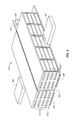
- FIGS. 2 and 3 are block diagrams showing perspective views of an exemplary sled of FIG. 1 removed from its enclosure.
- FIG. 4 is a block diagram of an exemplary embodiment of a backplane printed circuit assembly portion of the sled of FIGS. 1 through 3 .
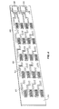
- FIGS. 5 and 6 are block diagrams describing exemplary embodiments of the backplane printed circuit assembly of FIGS. 1 through 4 in which connectors are positioned to reduce physical overlap of connectors on both sides of the backplane printed circuit assembly.
- FIG. 1 is a block diagram of an exemplary storage system 100 (e.g., a "rack" adapted for mounting storage enclosures and other components of a system) comprising a plurality of enclosures 102.
- Each enclosure 102 is adapted to house a plurality of storage devices 106 communicatively coupled through respective sleds 104 for communications with appropriate storage controllers and/or host systems.
- Each storage device 106 may be any suitable mass storage device including, for example, rotating magnetic or optical disk drives, solid-state drives, etc.
- Each storage device may be communicatively coupled utilizing any of several well-lcnown, commercially available communication media and protocols including, for example, Serial Attached SCSI (SAS), Serial Advanced Technology Attachment (SATA), parallel SCSI or ATA, etc.
- SAS Serial Attached SCSI
- SATA Serial Advanced Technology Attachment
- parallel SCSI or ATA etc.
- Each enclosure 102 comprises one or more sleds.
- Each sled 104 is adapted to receive a
- Each sled 104 of each enclosure 102 is adapted to slide out from a front opening of its respective enclosure and thereby provides access to each of the storage devices 106 coupled with the sled from the right and/or left side of the sled (viewing the system 100 from its front side).
- prior enclosure designs either provided access only to a limited number of storage devices accessed at the front opening of the enclosure or provided access to a larger number of storage devices through a top opening of the enclosure. Such top opening enclosures are difficult to access when the enclosure is positioned high in a storage system rack.
- a higher density of storage devices 106 may be coupled within enclosure 102 and all storage devices 106 are easily accessible from the left and right sides of sled 104 when the sled is slid forward out of the front opening of the enclosure regardless of the height at which the enclosure is mounted in the storage system.
- each enclosure 102 may comprise a front cover to cover the front opening (e.g., for aesthetics and/or to control cooling air flows).
- a front cover may be removable or may be hinged to allow access to sleds 104 enclosed within the enclosure 102. As shown in FIG. 1 , any such cover is removed for simplicity and brevity of this discussion.
- each enclosure 102 may be mounted within a storage system 100 and each enclosure may comprise any number of sleds 104 each adapted to receive any number of storage devices 106.
- FIG. 2 is a block diagram providing additional exemplary details of one sled 104.
- FIG. 2 is a block diagram showing a perspective top view of sled 104 removed from its enclosure 102.
- Sled 104 comprises backplane printer circuit assembly (PCA) 200 adapted to receive a plurality of storage devices 106.
- PCA 200 communicatively couples each of the plurality of storage devices 106 with one or more rear connectors 208 which, in turn, couples the storage devices with other components of the storage system (e.g., storage controllers and/or host systems).
- Rear connectors 208 may be simple passive components that merely extend electrical signals from the plurality of storage devices 106 to controlling components of the system (e.g., other components of system 100 and/or host systems).
- rear connectors 208 may comprise active components to convert the electrical signals from the plurality of storage devices 106 to another communication medium and protocol.
- storage devices 106 could be SATA storage devices and rear connectors 208 may convert the signals for transmission over a SAS communication medium and protocol.
- SAS storage devices 106 could be coupled through rear connectors 208 such that the signals are converted to Fibre Channel (FC) media and protocols.
- FC Fibre Channel
- Backplane PCA 200 is a substantially planar component having a first side and a second side substantially orthogonal to a front edge of backplane PCA 200.
- the first side comprises a plurality of connectors (not shown), each connector adapted to receive a mated connector from a corresponding storage device 106.
- cage 202.1 provides guidance and support for insertion and removal of storage devices 106. Cage 202.1 thus constrains each storage device 106 in an appropriate position to be mated with corresponding connector on the first side of backplane PCA 200.
- Cage 202.1 is adapted to couple with the right side (first side) of backplane PCA 200 to guide, position, and constrain storage devices 106 to be inserted and mated with connectors on the first side.
- Cage 202.1 may be attached (removably or otherwise) to backplane PCA 200 by any suitable means.
- sled 104 comprises a second cage 202.2 attached to the second side of backplane PCA 200.
- the second side of backplane PCA 200 also comprises a plurality of connectors (not shown), each connector adapted to receive a mated connector from a corresponding storage device 106.
- Cage 202.2 (like cage 202.1) guides, positions, and constrains storage devices 106 to be mated with the connectors on the second side of backplane PCA 200.
- Cage 202.2 (like cage 202.1) may be attached (removably or otherwise) to backplane PCA 200 by any suitable means.
- Holes 204.1 and 204.2 in cages 202.1 and 202.2, respectively, enable air flow through the cages and around storage devices 106 when inserted into the cages and coupled with corresponding connectors. Suitable fans (not shown) or other means may be employed in conjunction with the sleds and/or enclosures to provide any required air flow through holes 204.1 and 204.2.
- Slide members 206 are attached (removably or otherwise) to sled 104 to permit sled 104 to be slid forward out of the front opening of the enclosure in which the sled is housed.
- slide members 206 may be attached (removably or otherwise) to cages 202.1 and 202.2 on either side of backplane PCA 200.
- a single slide member 206 may be attached (removably or otherwise) directly to backplane PCA 200.
- Slide members may be any suitable sliding structure associated with sled 104 and with corresponding members of the storage system (i.e., elements within the enclosure or rack that permit slide members 206 and the attached sled 104 to slide forward out of the front opening of its enclosure.
- One or more rear connectors 208 of sled 104 serve to couple backplane PCA 200 (and its attached plurality of connectors and mated storage devices) to storage controllers and/or host systems. Ribbon cables, cable chains, wireless coupling, or other communicative coupling means that permit extension of the signaling medium may be employed to couple rear connectors 208 with storage controllers and/or host system so that all signal connections may remain active when sled 104 is slid forward in its enclosure (to permit access to storage devices 106).
- storage devices 106 may be accessed by a user from either the first or second side of backplane PCA 200 when sled 104 is slid forward and while power is applied (e.g., hot swaps of storage devices 106 may be more easily achieved as compared to prior enclosure designs).
- FIG. 3 is a block diagram showing a perspective bottom view of sled 104 removed from its enclosure 102. As compared to FIG. 2 , FIG. 3 shows a pair of rear connectors 208 permitting redundant coupling of storage devices 106 attached to backplane PCA 200 with external storage controllers and/or host systems. Further, additional holes 204.1 and 204.2 may be present in the rear sides of cages 202.1 and 202.2, respectively, further enhancing air flow around storage devices 106 through the cages.
- FIG. 4 is a diagram providing exemplary additional details of the first side of backplane PCA 200 with its cage and storage devices removed.
- a plurality of connectors 400 are arranged on the first side, each connector adapted to mate with a corresponding connector of a storage device.
- Each connector 400 may be any suitable connector appropriate for the desired communication media and protocol including, for example, SAS connectors, SATA connectors, and FC connectors.
- Signal traces 402 are suitably arranged on backplane PCA 200 to couple each connector 400 with each of rear connectors 208.
- some exemplary embodiments may provide multiple (i.e., redundant) rear connectors 208 coupled with each of connectors 400 through traces 402. Such redundant coupling may be preferred in high-reliability storage applications.
- traces 402 as shown in FIG. 4 are merely suggestive of the coupling between each connector and each of one or more rear connectors. Actual design and routing of such signal traces on backplane PCA 200 is a well-known matter of design choice. For example, many PCA designs provide multiple layer substrate boards such that traces may be routed along any of the several layers. Still further, as noted above, where both the first and second sides of backplane PCA 200 comprise a plurality of connectors 400, appropriate signal traces 402 also couple each of the connectors on the second side of backplane PCA 200 with each of the one or more rear connectors.
- FIGS. 5 and 6 are diagrams showing two exemplary embodiments for positioning and layout of connectors 400 on backplane PCA 200. Where both the first and second sides of backplane PCA 200 have a plurality of connectors 400 for coupling with storage devices 106, connectors 400 may be laid out on backplane PCA 200 to avoid or reduce physical overlap of the connectors on either side of the PCA. Such overlap may present undesired challenges in the manufacture of backplane PCA 200.
- backplane PCA 200 is viewed from its front edge and shows the plurality of connectors 400 staggered vertically on opposite sides of backplane PCA 200.
- FIG. 5 shows the plurality of connectors 400 staggered vertically on opposite sides of backplane PCA 200.
- FIG. 6 shows a second exemplary embodiment in which the plurality of connectors 400 on either side of backplane PCA 200 is staggered in a different pattern as compared to that of FIG. 5 . In the configuration of FIG.
- the plurality of connectors 400 on the second side of backplane PCA 200 are staggered relative to the plurality of connectors on the first side of backplane PCA 200 but in a different pattern than that of FIG. 5 .
- connectors 400 (and hence storage devices 106) on the second side are flipped upside down (i.e., inverted) relative to the orientation of connectors 400 (and hence storage devices 106) coupled with connectors 400 on the first side (right side as shown).
- the storage devices are positioned at symmetrical heights on both sides of backplane PCA 200. This symmetry may be beneficial for ease of manufacturing and/or for a reduced height dimension of the sled 104.
- Other configurations of the plurality of connectors 400 on either side of backplane PCA 200 may be beneficial for particular applications as a matter of design choice.
Landscapes
- Engineering & Computer Science (AREA)
- Theoretical Computer Science (AREA)
- Human Computer Interaction (AREA)
- Physics & Mathematics (AREA)
- General Engineering & Computer Science (AREA)
- General Physics & Mathematics (AREA)
- Computer Hardware Design (AREA)
- Power Engineering (AREA)
- Mounting Of Printed Circuit Boards And The Like (AREA)
- Microelectronics & Electronic Packaging (AREA)
- Details Of Connecting Devices For Male And Female Coupling (AREA)
Applications Claiming Priority (1)
| Application Number | Priority Date | Filing Date | Title |
|---|---|---|---|
| US13/217,650 US9019708B2 (en) | 2011-08-25 | 2011-08-25 | Apparatus and systems having storage devices in a side accessible drive sled |
Publications (1)
| Publication Number | Publication Date |
|---|---|
| EP2562616A2 true EP2562616A2 (de) | 2013-02-27 |
Family
ID=46146624
Family Applications (1)
| Application Number | Title | Priority Date | Filing Date |
|---|---|---|---|
| EP12165863A Withdrawn EP2562616A2 (de) | 2011-08-25 | 2012-04-27 | Vorrichtung und Systeme mit Speichervorrichtungen in einem Antriebsschlitten mit Seitenzugang |
Country Status (6)
| Country | Link |
|---|---|
| US (1) | US9019708B2 (de) |
| EP (1) | EP2562616A2 (de) |
| JP (1) | JP2013045440A (de) |
| KR (1) | KR101277005B1 (de) |
| CN (1) | CN102955674B (de) |
| TW (1) | TW201311118A (de) |
Cited By (1)
| Publication number | Priority date | Publication date | Assignee | Title |
|---|---|---|---|---|
| WO2018044384A1 (en) * | 2016-08-31 | 2018-03-08 | Western Digital Technologies, Inc. | Data storage device enclosure |
Families Citing this family (39)
| Publication number | Priority date | Publication date | Assignee | Title |
|---|---|---|---|---|
| US9763350B2 (en) | 2013-01-23 | 2017-09-12 | Seagate Technology Llc | High density data storage system with improved storage device access |
| US9001514B2 (en) * | 2013-01-23 | 2015-04-07 | Dot Hill Systems Corporation | Safe rackmountable storage enclosure |
| US9098233B2 (en) | 2013-01-23 | 2015-08-04 | Dot Hill Systems Corporation | Storage device carrier for high density storage system |
| US9198322B2 (en) | 2013-01-23 | 2015-11-24 | Dot Hill Systems Corporation | Compliant drawer latch assembly |
| US9456515B2 (en) | 2013-01-23 | 2016-09-27 | Seagate Technology Llc | Storage enclosure with independent storage device drawers |
| US9681576B2 (en) | 2013-01-23 | 2017-06-13 | Seagate Technology Llc | Shock dampening drawer slide |
| JP5926212B2 (ja) * | 2013-03-14 | 2016-05-25 | アラクサラネットワークス株式会社 | 通信装置 |
| US9489151B2 (en) | 2013-05-23 | 2016-11-08 | Netapp, Inc. | Systems and methods including an application server in an enclosure with a communication link to an external controller |
| US9671836B2 (en) * | 2013-07-10 | 2017-06-06 | Bae Systems Information And Electronic Systems Integration Inc. | Data storage transfer archive repository |
| US9585290B2 (en) | 2013-07-15 | 2017-02-28 | Skyera, Llc | High capacity storage unit |
| US10222842B2 (en) * | 2013-08-02 | 2019-03-05 | Amazon Technologies, Inc. | System for compute node maintenance with continuous cooling |
| US9600038B2 (en) * | 2013-11-21 | 2017-03-21 | Skyera, Llc | Systems and methods for securing high density SSDs |
| US9304557B2 (en) | 2013-11-21 | 2016-04-05 | Skyera, Llc | Systems and methods for packaging high density SSDS |
| US10846257B2 (en) * | 2014-04-01 | 2020-11-24 | Endance Technology Limited | Intelligent load balancing and high speed intelligent network recorders |
| US9992905B2 (en) * | 2014-05-30 | 2018-06-05 | Hewlett Packard Enterprise Development Lp | Supporting input/output (I/O) connectivity for a printed circuit assembly (PCA) in a hot aisle cabling or a cold aisle cabling arrangement |
| US9474190B1 (en) * | 2014-08-14 | 2016-10-18 | Amazon Technologies, Inc. | Computer system with side plenum cooling |
| US9715795B2 (en) * | 2014-10-30 | 2017-07-25 | International Business Machines Corporation | Indicator module for modular computing units |
| US9960562B2 (en) * | 2015-03-06 | 2018-05-01 | Facebook, Inc. | Circuit board actuator system |
| US9807901B2 (en) | 2015-03-06 | 2017-10-31 | Facebook, Inc. | Multiple graphics processing unit platform |
| TWI590741B (zh) * | 2015-04-16 | 2017-07-01 | 緯創資通股份有限公司 | 可裝載多個儲存單元的儲存單元結合模組、及可裝載多個儲存單元結合模組的儲存單元移動套件與其相關的伺服器設備 |
| US10025357B2 (en) * | 2015-06-15 | 2018-07-17 | Seagate Technology Llc | Enclosure system for computing equipment |
| US10028401B2 (en) * | 2015-12-18 | 2018-07-17 | Microsoft Technology Licensing, Llc | Sidewall-accessible dense storage rack |
| US10045459B2 (en) * | 2016-08-24 | 2018-08-07 | Facebook, Inc. | Server platform with integrated power supply |
| US10127947B2 (en) * | 2016-12-23 | 2018-11-13 | Western Digital Technologies, Inc. | Data storage system enclosure with central mounting plate |
| US10470335B2 (en) | 2017-08-17 | 2019-11-05 | Cisco Technology, Inc. | Configurable module guides for modular electronic system |
| US10042396B1 (en) * | 2017-08-17 | 2018-08-07 | Cisco Technology, Inc. | Configurable module guides for modular electronic system |
| US10687435B2 (en) * | 2017-08-28 | 2020-06-16 | Facebook, Inc. | Apparatus, system, and method for enabling multiple storage-system configurations |
| US10736228B2 (en) * | 2017-08-31 | 2020-08-04 | Facebook, Inc. | Removeable drive-plane apparatus, system, and method |
| US10537035B2 (en) | 2017-09-06 | 2020-01-14 | Facebook, Inc. | Apparatus, system, and method for securing hard drives in a storage chassis |
| US10558248B2 (en) | 2017-09-09 | 2020-02-11 | Facebook, Inc. | Apparatus, system, and method for indicating the status of and securing hard drives |
| US10588238B2 (en) | 2017-09-18 | 2020-03-10 | Facebook, Inc. | Apparatus, system, and method for partitioning a storage-system chassis |
| US10757831B2 (en) | 2017-09-26 | 2020-08-25 | Facebook, Inc. | Apparatus, system, and method for reconfiguring air flow through a chassis |
| US20220100233A1 (en) * | 2019-05-22 | 2022-03-31 | Hewlett-Packard Development Company, L.P. | Storage device carriers |
| CN110289026A (zh) * | 2019-06-26 | 2019-09-27 | 英业达科技有限公司 | 储存模块及其机壳 |
| EP3817531B1 (de) * | 2019-10-28 | 2023-10-25 | Chenbro Micom Co., Ltd. | Serversystem |
| US11653204B2 (en) * | 2020-01-21 | 2023-05-16 | Samsung Electronics Co., Ltd. | Sideband authentication of storage device |
| CN114650688A (zh) * | 2020-12-17 | 2022-06-21 | 华为技术有限公司 | 一种通信设备及通信系统 |
| US20240013815A1 (en) * | 2022-07-06 | 2024-01-11 | Christopher Scott George | High-density data storage systems and methods |
| TWI848794B (zh) * | 2023-08-11 | 2024-07-11 | 訊凱國際股份有限公司 | 電子裝置及浸沒式冷卻系統 |
Family Cites Families (14)
| Publication number | Priority date | Publication date | Assignee | Title |
|---|---|---|---|---|
| FR2704350B1 (fr) * | 1993-04-22 | 1995-06-02 | Bull Sa | Structure physique d'un sous système de mémoire de masse. |
| US6459571B1 (en) * | 2000-06-15 | 2002-10-01 | Bull Hn Information Systems Inc. | Packaging system for mass memory units |
| US6618260B2 (en) * | 2001-01-16 | 2003-09-09 | Sun Microsystems, Inc. | Removable expansion card cage |
| US6850410B2 (en) | 2001-06-29 | 2005-02-01 | Emc Corporation | Advanced technology attachment disk drive module with fibre channel system characteristics |
| US6618255B2 (en) * | 2002-02-05 | 2003-09-09 | Quantum Corporation | Quick release fastening system for storage devices |
| US6831839B2 (en) | 2002-02-28 | 2004-12-14 | Netezza Corporation | Adjustable sled module for mass storage devices |
| CN2626161Y (zh) * | 2003-04-28 | 2004-07-14 | 华为技术有限公司 | 一种双面插背板 |
| CN1299212C (zh) * | 2003-06-06 | 2007-02-07 | 英业达股份有限公司 | 可以动态存取外接式存储装置的计算机系统 |
| JP4391192B2 (ja) * | 2003-10-09 | 2009-12-24 | 株式会社日立製作所 | ディスクアレイ装置 |
| CN1670857A (zh) * | 2004-03-19 | 2005-09-21 | 大同股份有限公司 | 磁盘机固定结构 |
| JP4621039B2 (ja) | 2005-02-22 | 2011-01-26 | 株式会社日立製作所 | ディスク装置 |
| US7312999B1 (en) * | 2005-04-29 | 2007-12-25 | Network Appliance, Inc. | High density drive chassis assembly |
| US7583507B2 (en) * | 2006-03-31 | 2009-09-01 | Spectra Logic Corporation | High density array system having multiple storage units with active movable media drawers |
| KR200457753Y1 (ko) * | 2009-10-20 | 2012-01-02 | 조광현 | 초대형 데이터의 슈퍼 네트워크 컴퓨팅을 위한 서버 컴퓨터 실장장치 |
-
2011
- 2011-08-25 US US13/217,650 patent/US9019708B2/en not_active Expired - Fee Related
- 2011-11-07 TW TW100140586A patent/TW201311118A/zh unknown
- 2011-11-17 KR KR1020110120194A patent/KR101277005B1/ko not_active Expired - Fee Related
- 2011-11-22 CN CN201110371719.2A patent/CN102955674B/zh not_active Expired - Fee Related
- 2011-12-13 JP JP2011271813A patent/JP2013045440A/ja active Pending
-
2012
- 2012-04-27 EP EP12165863A patent/EP2562616A2/de not_active Withdrawn
Non-Patent Citations (1)
| Title |
|---|
| None |
Cited By (2)
| Publication number | Priority date | Publication date | Assignee | Title |
|---|---|---|---|---|
| WO2018044384A1 (en) * | 2016-08-31 | 2018-03-08 | Western Digital Technologies, Inc. | Data storage device enclosure |
| US10261553B2 (en) | 2016-08-31 | 2019-04-16 | Western Digital Technologies, Inc. | Data storage device enclosure |
Also Published As
| Publication number | Publication date |
|---|---|
| US9019708B2 (en) | 2015-04-28 |
| CN102955674A (zh) | 2013-03-06 |
| US20130050955A1 (en) | 2013-02-28 |
| TW201311118A (zh) | 2013-03-01 |
| KR20130023013A (ko) | 2013-03-07 |
| JP2013045440A (ja) | 2013-03-04 |
| KR101277005B1 (ko) | 2013-06-24 |
| CN102955674B (zh) | 2016-12-07 |
Similar Documents
| Publication | Publication Date | Title |
|---|---|---|
| US9019708B2 (en) | Apparatus and systems having storage devices in a side accessible drive sled | |
| US11604495B2 (en) | Computer system with side plenum cooling | |
| EP3817531B1 (de) | Serversystem | |
| US11032934B1 (en) | Apparatus, system, and method for enabling multiple storage-system configurations | |
| US9769947B1 (en) | Cable management for rack-mounted computing devices | |
| US8599550B2 (en) | Storage enclosure, carrier and methods | |
| US6816368B2 (en) | Disk array unit | |
| US8014144B2 (en) | Server device with a storage array module | |
| US8508928B2 (en) | Incorporation of multiple, 2.5-inch or smaller hard disk drives into a single drive carrier with a single midplane or baseboard connector | |
| CN102999089B (zh) | 服务器 | |
| US7742308B1 (en) | Increased drive density storage system having full serviceability | |
| US10349554B2 (en) | Apparatus, system, and method for directing air in a storage-system chassis | |
| US8508929B2 (en) | Implementing enhanced cover-mounted, auto-docking for multiple DASD configurations | |
| JP2008541237A (ja) | 記憶コンポーネントをエンクロージャ内に取り外し可能に固定するための装置 | |
| US20080298014A1 (en) | Modular electronic enclosure | |
| US20110007464A1 (en) | Modular system and retractable assembly for electronic devices | |
| US20050099771A1 (en) | Modular platform system and apparatus | |
| WO2010150320A1 (en) | Storage apparatus, storage controller for storage apparatus, chassis for storage controller | |
| US20140146462A1 (en) | High Density Storage Applicance | |
| US12555615B2 (en) | Storage server | |
| US20160363966A1 (en) | Enclosure system for computing equipment | |
| TWI590741B (zh) | 可裝載多個儲存單元的儲存單元結合模組、及可裝載多個儲存單元結合模組的儲存單元移動套件與其相關的伺服器設備 | |
| US10091906B2 (en) | Off-center component racking | |
| TWI675614B (zh) | 伺服器 | |
| US10928601B2 (en) | Network topology modules |
Legal Events
| Date | Code | Title | Description |
|---|---|---|---|
| PUAI | Public reference made under article 153(3) epc to a published international application that has entered the european phase |
Free format text: ORIGINAL CODE: 0009012 |
|
| AK | Designated contracting states |
Kind code of ref document: A2 Designated state(s): AL AT BE BG CH CY CZ DE DK EE ES FI FR GB GR HR HU IE IS IT LI LT LU LV MC MK MT NL NO PL PT RO RS SE SI SK SM TR |
|
| AX | Request for extension of the european patent |
Extension state: BA ME |
|
| STAA | Information on the status of an ep patent application or granted ep patent |
Free format text: STATUS: THE APPLICATION IS DEEMED TO BE WITHDRAWN |
|
| 18D | Application deemed to be withdrawn |
Effective date: 20151103 |