EP2562393A2 - Variable temperature chiller coils - Google Patents
Variable temperature chiller coils Download PDFInfo
- Publication number
- EP2562393A2 EP2562393A2 EP12180320A EP12180320A EP2562393A2 EP 2562393 A2 EP2562393 A2 EP 2562393A2 EP 12180320 A EP12180320 A EP 12180320A EP 12180320 A EP12180320 A EP 12180320A EP 2562393 A2 EP2562393 A2 EP 2562393A2
- Authority
- EP
- European Patent Office
- Prior art keywords
- chiller
- modules
- chiller coil
- temperature
- inlet
- Prior art date
- Legal status (The legal status is an assumption and is not a legal conclusion. Google has not performed a legal analysis and makes no representation as to the accuracy of the status listed.)
- Withdrawn
Links
- 239000012530 fluid Substances 0.000 claims abstract description 22
- 239000012809 cooling fluid Substances 0.000 claims abstract description 8
- XLYOFNOQVPJJNP-UHFFFAOYSA-N water Substances O XLYOFNOQVPJJNP-UHFFFAOYSA-N 0.000 claims description 24
- 238000000034 method Methods 0.000 claims description 10
- 238000011144 upstream manufacturing Methods 0.000 claims description 2
- 239000003570 air Substances 0.000 description 40
- 238000001816 cooling Methods 0.000 description 7
- 230000001276 controlling effect Effects 0.000 description 3
- 239000002826 coolant Substances 0.000 description 3
- 230000007704 transition Effects 0.000 description 3
- 230000003416 augmentation Effects 0.000 description 2
- 238000010276 construction Methods 0.000 description 2
- 238000010586 diagram Methods 0.000 description 2
- 239000000446 fuel Substances 0.000 description 2
- 238000010438 heat treatment Methods 0.000 description 2
- 229910000746 Structural steel Inorganic materials 0.000 description 1
- WYTGDNHDOZPMIW-RCBQFDQVSA-N alstonine Natural products C1=CC2=C3C=CC=CC3=NC2=C2N1C[C@H]1[C@H](C)OC=C(C(=O)OC)[C@H]1C2 WYTGDNHDOZPMIW-RCBQFDQVSA-N 0.000 description 1
- 239000012080 ambient air Substances 0.000 description 1
- 238000000576 coating method Methods 0.000 description 1
- 239000000498 cooling water Substances 0.000 description 1
- 230000003247 decreasing effect Effects 0.000 description 1
- 238000013461 design Methods 0.000 description 1
- 230000000694 effects Effects 0.000 description 1
- 239000000463 material Substances 0.000 description 1
- 238000012986 modification Methods 0.000 description 1
- 230000004048 modification Effects 0.000 description 1
- 238000012544 monitoring process Methods 0.000 description 1
- 230000002250 progressing effect Effects 0.000 description 1
- 230000001105 regulatory effect Effects 0.000 description 1
- 238000013517 stratification Methods 0.000 description 1
Images

Classifications
-
- F—MECHANICAL ENGINEERING; LIGHTING; HEATING; WEAPONS; BLASTING
- F02—COMBUSTION ENGINES; HOT-GAS OR COMBUSTION-PRODUCT ENGINE PLANTS
- F02C—GAS-TURBINE PLANTS; AIR INTAKES FOR JET-PROPULSION PLANTS; CONTROLLING FUEL SUPPLY IN AIR-BREATHING JET-PROPULSION PLANTS
- F02C7/00—Features, components parts, details or accessories, not provided for in, or of interest apart form groups F02C1/00 - F02C6/00; Air intakes for jet-propulsion plants
- F02C7/12—Cooling of plants
- F02C7/14—Cooling of plants of fluids in the plant, e.g. lubricant or fuel
- F02C7/141—Cooling of plants of fluids in the plant, e.g. lubricant or fuel of working fluid
- F02C7/143—Cooling of plants of fluids in the plant, e.g. lubricant or fuel of working fluid before or between the compressor stages
- F02C7/1435—Cooling of plants of fluids in the plant, e.g. lubricant or fuel of working fluid before or between the compressor stages by water injection
Definitions
- the present application relates generally to gas turbines and more particularly, to a chiller coil arrangement in a gas turbine inlet filter house.
- Each chiller coil module may be provided with a cooled fluid inlet pipe and a warmed fluid outlet pipe, each warmed fluid outlet pipe connected to the common return pipe, wherein at least some of the cooled fluid inlet pipes are connected to the common return pipe, and wherein a mixing control valve controls an amount of warmed fluid in the common return pipe to be added to the at least some of said inlet pipes.
- the invention provides a method of controlling temperature of inlet air flowing across a chiller coil assembly of a gas turbine, wherein the chiller coil assembly comprises a plurality of substantially vertically aligned chiller modules and wherein inlet air flow velocity varies across the chiller modules as a function of vertical height of the chiller modules, the method comprising determining temperature differential of the inlet air downstream of each module, and differentially adjusting temperature of cooling fluid in the plurality of chiller modules to produce a substantially uniform temperature for the inlet air downstream of the chiller coil assembly.
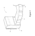
- Fig. 1 illustrates a typical asymmetrical gas turbine filter house 10 including a filter section and chiller coil housing portion 12 and outlet duct portions 14, 16 leading to the compressor (not shown).
- a louvered inlet 18 guides outside or ambient air into the filter house, and it can be appreciated that the inlet flow velocity profile varies with height within the upstanding filter and chiller coil housing portion 12.
- chiller coil shown in dashed pipes is arranged substantially vertically (and upstream or downstream of filter elements (not shown)), and that air velocity and hence the temperature across and about the chiller coil will also vary by height in that, for example, air entering at the top of the filter housing, across the coils 20 (described below) and down the back wall to the outlet duct 14 will have a lower velocity and thus a greater time exposure to the cooling coils than air entering the filter house at the bottom of the chiller unit where the velocity is greater.
- air downstream of the chiller coils in the lower portion of duct sections 14, 16 will have higher temperatures than air in the upper portion of the duct sections.
- the exemplary but nonlimiting embodiment of the invention described herein seeks to make that inlet air temperature more uniform throughout the post coil vertical section 12, the duct sections 14 and 16 and hence the compressor.
- the chiller coil assembly 20 is comprised of plural, individual but substantially identical vertically-oriented stacks of chiller coil modules 22, each of which supports a serpentine array of finned heat exchange tubes indicated generally at 24.
- the stacks of chiller coil modules 22 are divided into two side-by-side groups, Group A on the left-hand side and Group B on the right-hand side. Within each group, there are three sets 1, 2 and 3 of two coils each. Thus, within the Group A stack, modules 26 and 28 form the first set 1; modules 30 and 32 form the second set 2; and modules 34, 36 form the third set 3.
- the module arrangement and control valve arrangement for the Group B stack is substantially identical to that of Group A, and therefore, only Group A will be described in detail, except as otherwise noted.
- Chilled water (or other suitable cooling fluid) is supplied to the Group A stack of modules via common supply pipe 38.
- Each module is supplied individually by respective branch pipes 42, 44, 46, 48, 50 and 52.
- the cooling water exiting the modules via respective return branch pipes 54, 56, 58, 60, 62 and 64 joins to a common return pipe 39 which returns the newly-"warmed" water (due to heat exchange with the inlet air flowing across the module coils) to cooling towers (not shown) which ultimately return chilled water to the supply pipe 38.
- a separate manual vent valve 60 relieves pressure in the system as necessary. Vent valves 40 and 68 are for automatic vents and are in a normally open position.
- inlet air velocity over the chiller coils varies by location. As already noted above, it has been determined that for some asymmetric filter house configurations, the air velocity through the two lowermost modules 26, 28 of the Group A stack (and laterally-aligned modules 126, 128 of the Group B stack) is higher, thereby resulting in air flow that is warmer due to a shorter residence time in the coil section. Conversely, with decreased velocity across the two uppermost, modules 34, 36, (and laterally-aligned modules 134, 136 of the Group B stack) the inlet air downstream of the chiller coils is cooler due to longer residence time in the coil section.
- the inlet air temperature through the mid portion of the chiller coils, including modules 30, 32 and 130, 132 lies in between the temperature of the inlet air passing through the upper and lower sets of modules 36, 34 and 28, 26, respectively.
- the chiller supply/return configuration is modified in accordance with a first exemplary but nonlimiting embodiment described below.
- the chilled water supply is mixed with warmed return water.
- the branch inlet pipes 46, 48 of the mid-height modules 30 and 32 are connected by pipes 70 and 72 to the common return pipe 39 under the control of respective valves 74 and 76 which control the amount of warmed or return water to be added to the branch inlet pipes 46, 48.
- the branch inlet pipes 50, 52 are connected by pipes 78 and 80 to the common return pipe 39 under the control of respective valves 82 and 84 which control the amount of warmed or return water to be added to the branch inlet pipes 50, 52.
- the goal is to have coldest water temperature flowing through the lowest module sets 26 and 28 and relatively less colder water through sets 30 and 32 and relatively least cold water through sets 34 and 36.
- the water temperature profile through the chiller coil modules 22 is counteracting the velocity profile. In the highest velocity area (lowest height section), residence time is lowest and water temperature is coldest. Progressing towards the top of the stacks of chiller coil modules 22, the velocity is the lowest, resulting residence time is highest and the water temperature is least cold. This evens out the overall air temperature profile across the height of the stacks of modules 22. In other words, in the described system thermal stratification is achieved to counter the effects of variable velocity.
- the controlled addition of warmed return water is substantially the same for mid-height modules 30 and 32, and a proportionately greater addition of warmed return water is made with respect to the upper-height modules 34 and 36. It is nevertheless possible to treat each module individually rather than in pairs.
- a conventional drain trough 86 catches condensate formed on the outside of the various modules and routes it to a drain box 87. From the drain box, condensed water returns to the cooling towers where it is cooled and recycled to the chiller coils. Alternatively, the condensate can be drained off at the nearest drain point. Both alternatives are practiced in the industry.
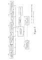
- FIG. 3 an exemplary but nonlimiting control system for monitoring and adjusting the water supplied to the various modules is illustrated.
- a chiller coil controller 88 interfaces with a chiller plant controller 90 and a gas turbine controller 92.
- the chiller coil controller receives signals from sensors/thermocouples 94, 96, 98, 100, 102 and 104, respectively corresponding to: inlet air temperature, inlet air velocity, chilled water return temperature from module pairs, chilled water supply flow, chilled water supply temperature, downstream air temperature.
- Another embodiment of this system can also be utilized where the chiller coil controller resides in the chiller plant controller.
- the chiller coil controller 88 outputs control signals the various mixing valves 74, 76, 82, 84 to achieve the desired coolant temperature profile.
- the chiller coil system is regulated to achieve a substantially uniform air temperature downstream of the chiller coils, thus compensating for the different velocity profiles across the coils resulting from the asymmetric filter house geometry.
- the fin density, material of construction, coatings or the geometry of the individual heat exchanger tubes and fins in the various coils, and/or the heat exchange properties or mass flow of the cooling fluid may be altered as needed to obtain the desired uniformity of inlet air temperature.
- the chilling coil system as described herein can be employed on essentially all existing gas turbines where transitions are asymmetric or where velocity profile is not uniform, and where the power demands warrant inlet air cooling. It can be also employed on new units where asymmetric transitions are necessary (to save cost of structural steel) when specified along the inlet air cooling.
- the chilling coil system as described herein can also be employed on applications requiring inlet air heating for gas turbines where transitions are asymmetric and the gas turbine operation warrants inlet air heating.
- the principle of design and operation is similar to the system explained above except for the fact that the purpose is to heat the inlet air.
- the chiller coil system can also be used in circumstances where the plurality of chiller modules are supplied with coolant at different temperatures from a cooling source. In this arrangement mixing valves and return water mixing are not used; however, all modules are independently supplied with coolant at different temperatures directly from the cooling source.
Landscapes
- Engineering & Computer Science (AREA)
- Chemical & Material Sciences (AREA)
- Combustion & Propulsion (AREA)
- Mechanical Engineering (AREA)
- General Engineering & Computer Science (AREA)
- Heat-Exchange Devices With Radiators And Conduit Assemblies (AREA)
- Devices That Are Associated With Refrigeration Equipment (AREA)
Applications Claiming Priority (1)
| Application Number | Priority Date | Filing Date | Title |
|---|---|---|---|
| US13/215,583 US20130048265A1 (en) | 2011-08-23 | 2011-08-23 | Variable temperature chiller coils |
Publications (1)
| Publication Number | Publication Date |
|---|---|
| EP2562393A2 true EP2562393A2 (en) | 2013-02-27 |
Family
ID=46829637
Family Applications (1)
| Application Number | Title | Priority Date | Filing Date |
|---|---|---|---|
| EP12180320A Withdrawn EP2562393A2 (en) | 2011-08-23 | 2012-08-13 | Variable temperature chiller coils |
Country Status (4)
| Country | Link |
|---|---|
| US (1) | US20130048265A1 (enExample) |
| EP (1) | EP2562393A2 (enExample) |
| JP (1) | JP2013044327A (enExample) |
| CN (1) | CN102953829A (enExample) |
Cited By (1)
| Publication number | Priority date | Publication date | Assignee | Title |
|---|---|---|---|---|
| EP3242003A3 (en) * | 2016-05-03 | 2018-03-14 | General Electric Company | Liquid injection apparatus and compressor assembly having the same |
Families Citing this family (3)
| Publication number | Priority date | Publication date | Assignee | Title |
|---|---|---|---|---|
| US20160237902A1 (en) * | 2013-11-05 | 2016-08-18 | Jianmin Zhang | Gas turbine inlet air conditioning coil system |
| US10035095B2 (en) | 2016-03-04 | 2018-07-31 | General Electric Company | Diverted pulse jet cleaning device and system |
| CN106644489B (zh) * | 2016-09-30 | 2019-06-18 | 西安航天动力试验技术研究所 | 非对称结构推进剂均衡供应装置及设计方法 |
Citations (2)
| Publication number | Priority date | Publication date | Assignee | Title |
|---|---|---|---|---|
| US20050056023A1 (en) | 1999-08-06 | 2005-03-17 | Pierson Tom L. | Method of chilling inlet air for gas turbines |
| US7007484B2 (en) | 2003-06-06 | 2006-03-07 | General Electric Company | Methods and apparatus for operating gas turbine engines |
Family Cites Families (15)
| Publication number | Priority date | Publication date | Assignee | Title |
|---|---|---|---|---|
| US5193352A (en) * | 1991-05-03 | 1993-03-16 | Amsted Industries, Inc. | Air pre-cooler method and apparatus |
| SE469042B (sv) * | 1991-09-13 | 1993-05-03 | Abb Carbon Ab | Foerfarande och anordning foer att reglera och begraensa luftens temperatur paa en i en pfbc-anlaeggning ingaaende hoegtryckskompressors in- och utlopp |
| DE4337674A1 (de) * | 1992-11-17 | 1994-05-19 | Elin Energieversorgung | Verfahren zur Eisfreihaltung des Frischluft-Ansaugfilters von Gas-Dampfturbinenanlagen |
| US5390505A (en) * | 1993-07-23 | 1995-02-21 | Baltimore Aircoil Company, Inc. | Indirect contact chiller air-precooler method and apparatus |
| JPH11173162A (ja) * | 1997-07-22 | 1999-06-29 | Yoshihide Nakamura | ガスタービンシステムとその夏期における吸気冷却方法 |
| US6145294A (en) * | 1998-04-09 | 2000-11-14 | General Electric Co. | Liquid fuel and water injection purge system for a gas turbine |
| JP3723943B2 (ja) * | 1999-10-05 | 2005-12-07 | 吉秀 中村 | ガスタービンプラント及びその吸気冷却方法 |
| US6634165B2 (en) * | 2000-12-28 | 2003-10-21 | General Electric Company | Control system for gas turbine inlet-air water-saturation and supersaturation system |
| US8109104B2 (en) * | 2004-08-25 | 2012-02-07 | York International Corporation | System and method for detecting decreased performance in a refrigeration system |
| CN2799870Y (zh) * | 2005-06-22 | 2006-07-26 | 陆钧 | 燃气轮机组进气冷却装置 |
| JP4831820B2 (ja) * | 2006-05-22 | 2011-12-07 | 三菱重工業株式会社 | ガスタービン出力学習回路及びこれを備えたガスタービンの燃焼制御装置 |
| JP5423080B2 (ja) * | 2009-03-18 | 2014-02-19 | 富士電機株式会社 | 局所冷却システム、その制御装置、プログラム |
| JP2010216765A (ja) * | 2009-03-18 | 2010-09-30 | Fuji Electric Systems Co Ltd | 局所冷却システム |
| CN102686852B (zh) * | 2010-02-15 | 2016-02-24 | 唐纳森公司 | 用于燃气涡轮机进气系统的线圈结构和方法 |
| CN103470379B (zh) * | 2013-09-09 | 2016-02-17 | 无锡金龙石化冶金设备制造有限公司 | 组合式节能型燃气轮机进气冷却系统 |
-
2011
- 2011-08-23 US US13/215,583 patent/US20130048265A1/en not_active Abandoned
-
2012
- 2012-08-13 EP EP12180320A patent/EP2562393A2/en not_active Withdrawn
- 2012-08-16 JP JP2012180294A patent/JP2013044327A/ja not_active Ceased
- 2012-08-23 CN CN2012103019142A patent/CN102953829A/zh active Pending
Patent Citations (2)
| Publication number | Priority date | Publication date | Assignee | Title |
|---|---|---|---|---|
| US20050056023A1 (en) | 1999-08-06 | 2005-03-17 | Pierson Tom L. | Method of chilling inlet air for gas turbines |
| US7007484B2 (en) | 2003-06-06 | 2006-03-07 | General Electric Company | Methods and apparatus for operating gas turbine engines |
Cited By (3)
| Publication number | Priority date | Publication date | Assignee | Title |
|---|---|---|---|---|
| EP3242003A3 (en) * | 2016-05-03 | 2018-03-14 | General Electric Company | Liquid injection apparatus and compressor assembly having the same |
| US10670018B2 (en) | 2016-05-03 | 2020-06-02 | General Electric Company | Liquid injection apparatus and compressor assembly having the same |
| US11248610B2 (en) | 2016-05-03 | 2022-02-15 | General Electric Company | Liquid injection apparatus and compressor assembly having the same |
Also Published As
| Publication number | Publication date |
|---|---|
| US20130048265A1 (en) | 2013-02-28 |
| CN102953829A (zh) | 2013-03-06 |
| JP2013044327A (ja) | 2013-03-04 |
Similar Documents
| Publication | Publication Date | Title |
|---|---|---|
| US6213200B1 (en) | Low profile heat exchange system and method with reduced water consumption | |
| US9151488B2 (en) | Start-up system for a once-through horizontal evaporator | |
| US9377250B2 (en) | Cross-flow heat exchanger having graduated fin density | |
| US8235365B2 (en) | Natural draft air cooled steam condenser and method | |
| EP2562393A2 (en) | Variable temperature chiller coils | |
| JP6329786B2 (ja) | 空調機の熱交換器 | |
| JP4937240B2 (ja) | 冷凍サイクル装置 | |
| JP6397853B2 (ja) | 低温液体を気化するシステム | |
| JP5197819B2 (ja) | 分配器並びに冷凍サイクル装置 | |
| US10961909B2 (en) | Variable evaporative cooling system | |
| US11761677B2 (en) | Water heater having highly efficient and compact heat exchanger | |
| RU2685158C1 (ru) | Выхлопная система газоперекачивающего агрегата | |
| JP6286548B2 (ja) | 貫流式蒸気発生器 | |
| CN110234953B (zh) | 具有气流扩散器的空冷式冷凝器 | |
| CN112985128A (zh) | 矿井新风加热系统中的多通道与多流程换热器 | |
| Mandal | Air Coolers Versus Shell-and-Tube Water Coolers. | |
| JP2005321336A (ja) | 原子力施設ユーティリティ流体供給システムおよび方法 |
Legal Events
| Date | Code | Title | Description |
|---|---|---|---|
| PUAI | Public reference made under article 153(3) epc to a published international application that has entered the european phase |
Free format text: ORIGINAL CODE: 0009012 |
|
| AK | Designated contracting states |
Kind code of ref document: A2 Designated state(s): AL AT BE BG CH CY CZ DE DK EE ES FI FR GB GR HR HU IE IS IT LI LT LU LV MC MK MT NL NO PL PT RO RS SE SI SK SM TR |
|
| AX | Request for extension of the european patent |
Extension state: BA ME |
|
| STAA | Information on the status of an ep patent application or granted ep patent |
Free format text: STATUS: THE APPLICATION IS DEEMED TO BE WITHDRAWN |
|
| 18D | Application deemed to be withdrawn |
Effective date: 20170301 |