EP2562356A1 - Agencement de pales - Google Patents
Agencement de pales Download PDFInfo
- Publication number
- EP2562356A1 EP2562356A1 EP11178635A EP11178635A EP2562356A1 EP 2562356 A1 EP2562356 A1 EP 2562356A1 EP 11178635 A EP11178635 A EP 11178635A EP 11178635 A EP11178635 A EP 11178635A EP 2562356 A1 EP2562356 A1 EP 2562356A1
- Authority
- EP
- European Patent Office
- Prior art keywords
- blade
- groove
- bead
- blade assembly
- assembly
- Prior art date
- Legal status (The legal status is an assumption and is not a legal conclusion. Google has not performed a legal analysis and makes no representation as to the accuracy of the status listed.)
- Withdrawn
Links
Images


Classifications
-
- F—MECHANICAL ENGINEERING; LIGHTING; HEATING; WEAPONS; BLASTING
- F01—MACHINES OR ENGINES IN GENERAL; ENGINE PLANTS IN GENERAL; STEAM ENGINES
- F01D—NON-POSITIVE DISPLACEMENT MACHINES OR ENGINES, e.g. STEAM TURBINES
- F01D5/00—Blades; Blade-carrying members; Heating, heat-insulating, cooling or antivibration means on the blades or the members
- F01D5/30—Fixing blades to rotors; Blade roots ; Blade spacers
- F01D5/32—Locking, e.g. by final locking blades or keys
- F01D5/323—Locking of axial insertion type blades by means of a key or the like parallel to the axis of the rotor
-
- F—MECHANICAL ENGINEERING; LIGHTING; HEATING; WEAPONS; BLASTING
- F01—MACHINES OR ENGINES IN GENERAL; ENGINE PLANTS IN GENERAL; STEAM ENGINES
- F01D—NON-POSITIVE DISPLACEMENT MACHINES OR ENGINES, e.g. STEAM TURBINES
- F01D5/00—Blades; Blade-carrying members; Heating, heat-insulating, cooling or antivibration means on the blades or the members
- F01D5/30—Fixing blades to rotors; Blade roots ; Blade spacers
- F01D5/3023—Fixing blades to rotors; Blade roots ; Blade spacers of radial insertion type, e.g. in individual recesses
- F01D5/303—Fixing blades to rotors; Blade roots ; Blade spacers of radial insertion type, e.g. in individual recesses in a circumferential slot
- F01D5/3038—Fixing blades to rotors; Blade roots ; Blade spacers of radial insertion type, e.g. in individual recesses in a circumferential slot the slot having inwardly directed abutment faces on both sides
-
- F—MECHANICAL ENGINEERING; LIGHTING; HEATING; WEAPONS; BLASTING
- F01—MACHINES OR ENGINES IN GENERAL; ENGINE PLANTS IN GENERAL; STEAM ENGINES
- F01D—NON-POSITIVE DISPLACEMENT MACHINES OR ENGINES, e.g. STEAM TURBINES
- F01D5/00—Blades; Blade-carrying members; Heating, heat-insulating, cooling or antivibration means on the blades or the members
- F01D5/30—Fixing blades to rotors; Blade roots ; Blade spacers
- F01D5/32—Locking, e.g. by final locking blades or keys
- F01D5/326—Locking of axial insertion type blades by other means
-
- F—MECHANICAL ENGINEERING; LIGHTING; HEATING; WEAPONS; BLASTING
- F04—POSITIVE - DISPLACEMENT MACHINES FOR LIQUIDS; PUMPS FOR LIQUIDS OR ELASTIC FLUIDS
- F04D—NON-POSITIVE-DISPLACEMENT PUMPS
- F04D29/00—Details, component parts, or accessories
- F04D29/26—Rotors specially for elastic fluids
- F04D29/32—Rotors specially for elastic fluids for axial flow pumps
- F04D29/321—Rotors specially for elastic fluids for axial flow pumps for axial flow compressors
- F04D29/322—Blade mountings
Definitions
- the invention relates to a blade arrangement according to the preamble of claim 1.
- Such blade arrangements are well known from the extensive prior art.
- the known blade arrangements are used both for rows of blades and for blade rows of compressors, wherein in a blade carrier, a circumferential groove for receiving all the blades of the series is provided.
- the attachment of the blades in the circumferential groove takes place with the aid of a hammer-shaped or dovetail-like positive connection by correspondingly designed blade roots engage behind projections protruding from the side walls of the retaining groove.
- the object of the invention is therefore to provide a blade assembly in which a durable and reliable and secure fastening of the blades in the circumferential groove is ensured with simple assembly and disassembly.
- each element is plate-shaped, has at least one bead arranged below the blade in the projection of the blade blade groove for pressing the blade in the groove and in the longitudinal direction of the retaining only partially covered by him pressed blade root.
- the element With the aid of the element according to the invention, it is possible that this has a particularly suitable shape, which allows a locally resilient substructure and at another local point a rigid-looking substructure.
- the element is particularly easy to manufacture and, on the other hand, it is particularly easy to assemble and disassemble.
- the stiffening effect is generated by a bead or several beads.
- the ease of assembly and disassembly is achieved in that in the longitudinal direction of the retaining the element in question is only partially covered by the pressed by him blade root. Thus, always a section of the element stands out, which is particularly easy to reach for a disassembly tool.
- the plate-shaped geometry of the element allows a space-saving design and blade arrangement.
- a one-piece or multi-piece intermediate piece is inserted, which is pressed by the not covered by the blade root part of the element to the projections.
- a one-piece or multi-piece intermediate piece is inserted, which is pressed by the not covered by the blade root part of the element to the projections.
- the elements have a longitudinal extent which is equal to the longitudinal extent of blade root and intermediate piece.
- the assembly of the elements is offset with respect to spacers and blades, so that the element - viewed in the longitudinal direction of the retaining - extends completely under the blade root and each partially extends below the two, the blade root adjacent spacers.
- each intermediate piece of two elements is pressed against the projections of the retaining groove.
- the elements are designed such that the respective intermediate pieces are pressed against the projections with less force than the pressed by the respective element to the projections blade root.
- different stiffnesses of the element can be used particularly advantageously for different requirements.
- a lower spring force of the element is desirable and not needed, since in operation also do not attack high forces on the intermediate piece.
- the blades clamped in the blade carrier are exposed to flow forces during operation. This requires a more reliable attachment of the blades to the blade carrier, which requires a larger contact force.
- the higher contact pressure is achieved by the locally higher rigidity of the element. This will be caused by the bead (s) arranged in the element.
- the local material plasticization of the bead is provided to compensate for manufacturing tolerances during assembly.
- a use of the residual elasticity is provided to then absorb the operating forces.
- a material is advantageously used for the element, which is characterized by a relatively high ratio of the index for maximum tensile strength (Rmax) to the yield strength (RP0.2) (Index Rmax / Rp0.2> 1.5), whereby with material choice the yield strength at the same time still sufficiently large enough for the operating force must be.
- a third bead geometry as a combination of the first two bead geometries with similar properties leads to a double bead, which has a further enlarged elastic range.
- the beads are located in the element so that they are arranged in the projection of the blade leaf groove bottom direction below the blade.
- the beads are arranged in principle in the interior of the element or at its edge. This allows easy assembly and disassembly of the elements.
- the element has at least one opening in its area not covered by the blade root. In this opening can engage a disassembly hook or tool to disassemble it from its operating position.
- a simple mountability of the element can be achieved if a groove extending along the retaining groove is located as a disassembly groove in the groove bottom of the retaining groove or in the blade root underside.
- a slide hammer can be comparatively easily attached there and during assembly, the insertion / compression of the element between the blade and the groove is simplified by means of a plunger.
- the element expediently has an outer contour in the projection of the blade leaf in the direction of the groove bottom (radial viewing axis), which is substantially rectangular. In this projection, the element in question is only half covered by the blade pressed by it.
- Such contoured elements are particularly inexpensive and easy to produce.
- At least one longitudinal edge of the element is angled, which bears biased against the correspondingly shaped blade roots. If intermediate pieces are used in the blade arrangement, the angled longitudinal edges can also be prestressed against the correspondingly shaped intermediate pieces.
- This embodiment makes it possible that the blades are not aligned solely on the basis of the groove geometry and the Schaufelfußgeometrie, but also on the basis of the respective neighboring component - blade or spacer - align. This feature serves to advantageously reduce contact wear.
- the element on at least one edge at least one further bead for local reinforcement and for guiding the element in a guide groove.
- This further bead on the edge preferably the transverse edge, can simplify the assembly, because at the local stiffening a plunger for driving / pushing the element between the blade root underside and groove base can be applied without the element during subsequent driving, the element bends locally.
- the bead is designed as an inner bead, which is located in an at least partially surrounding, outer bead. This embodiment, also referred to as a double bead, makes it possible to increase the elastic range of the element.
- the blade assembly is used in an axially flow-through compressor of a gas turbine, either for a blade ring and / or for a vane ring.
- a gas turbine either for a blade ring and / or for a vane ring.
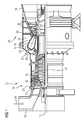
- FIG. 1 shows a stationary gas turbine 10 in a longitudinal partial section.
- the gas turbine 10 has inside a rotatably mounted about an axis of rotation 12 rotor 14, which is also referred to as a turbine runner.
- rotor 14 successively follow an intake housing 16, a Axialturbover Noticer 18, a toroidal annular combustion chamber 20 with a plurality of rotationally symmetrical mutually arranged burners 22, a turbine unit 24 and an exhaust housing 26th
- the Axialturbover Noticer 18 includes a ring-shaped compressor duct with cascading successively compressor stages of blade and Leitschaufelkränzen.
- the rotor blades 14 arranged on the blades 27 lie with their free-ending blade tips 29 of an outer channel wall 42 of the compressor passage opposite. Also protrude vanes 25 which are secured to the outer duct wall 42 or to a Ver Whyrleitschaufelani.
- the compressor duct discharges via a compressor outlet diffuser 36 in a plenum 38.
- the annular combustion chamber 20 is provided with its combustion chamber 28, which communicates with an annular hot gas duct 30 of the turbine unit 24. In the turbine unit 24 four successive turbine stages 32 are arranged.
- a generator or a working machine (each not shown) is coupled.
- the axial turbocharger 18 draws in ambient air 34 through the intake housing 16 as a medium to be compressed and compresses it.
- the compressed air is guided through the compressor outlet diffuser 36 into the plenum 38, from where it flows into the burner 22.
- Fuel also passes into the combustion space 28 via the burners 22.
- the fuel is burned to a hot gas M with the addition of the compressed air.
- the hot gas M then flows into the hot gas duct 30, where it relaxes to perform work on the turbine blades of the turbine unit 24.
- the energy released during this time is absorbed by the rotor 14 and used on the one hand to drive the axial turbocharger 18 and on the other hand to drive a working machine or electric generator.
- FIG. 2 shows a plan view of a portion of a blade assembly 40, in which only two blades 25, 27 with an intermediate intermediate piece 44 and two underneath arranged elements 46 are schematically dargterrorism.
- the blades 25, 27 comprise a schematically indicated blade 48 and a blade root 50.
- the plan view is taken in the direction of the radial direction of the gas turbine 10, ie from the blade in the direction of the blade root 50 FIG. 2 not shown is the blade carrier and a holding groove arranged in the carrier.
- the elements 46 have a rectangular outer contour and are plate-shaped. Colloquially, they are also referred to as sheet-shaped.
- the blade roots 50 and the blades 25, 27 of the blade assembly with respect to a longitudinal extent of the retaining groove or a circumferential direction U arranged obliquely. This employment is typical for blades.
- Each element 46 has two beads 52 and two openings 54, respectively.
- the elements 46 are in the circumferential direction U as long as the blade root 50 and spacer 44 together. However, the elements 46 are arranged centrally below the respective blade 25, 27, so that two adjacent elements 46 each end centrally with their opposite ends below the intermediate pieces 44.
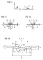
- FIG. 3 shows the cross section along section line III-III through the blade root 50 of the blade 25, 27 and a blade carrier 56.
- the blade is in FIG. 3 (and also in the FIGS. 5, 6 . 8, 9 . 11 and 12 ) not shown.
- a retaining groove 58 extends, in which the blades 25, 27, in detail the blade roots 50 of the blades 25, 27, are inserted in a form-fitting manner.
- the side walls 60 of the retaining grooves 58 have longitudinally extending projections 62 for forming undercuts 64.
- hammer-shaped foot regions 66 engage in the undercut 64.
- the element 46 is braced.
- a further, along the retaining groove 58 extending disassembly groove 72 is provided in the groove bottom 70.
- the further groove 72 serves for the access of a disassembly tool, such as a slide hammer.
- the wall thickness S of the element 46 ( FIG. 14 ) is less than the gap between the blade root bottom 68 and groove bottom 70.
- the beads 52 produced in the element 46 by deep drawing or by pressing increase the height H of the element 46 beyond the gap, so that the blade root 50 is pressed against the projections 62. This leads to a clearly defined position of the blades 25, 27 in the retaining groove 58.
- FIG. 4 shows the longitudinal section through the embodiment according to FIG. 2 along the section line IV-IV.
- the blade assembly 40 is a section of a blade ring of a compressor 12 of the gas turbine 10. Accordingly, the blade carrier 56 is formed by a rotor disk and the blades 25, 27 formed as blades.
- the elements 46 are substantially planar and thus do not follow the curvature of the retaining groove 58. As a result, the elements 46 press with their central region in which the beads 52 are arranged with greater force blade root lower side 68 and groove bottom 70 apart. The adjacent to the transverse edges 82 portions of the element 46 are due to the planar configuration of the elements 46 and the curved retaining groove 58 then with less force resiliently against the undersides of the intermediate pieces 44. Consequently, the element 46 presses the intermediate pieces 44 and the blades 25, 27 against the projections 62 of the retaining groove 58 due to locally different stiffnesses with forces of different magnitude.
- FIG. 5 shows essentially the cross section according to FIG. 3 , Here are in FIG. 5 to FIG. 3 identical features provided with the identical reference numerals. To the description of FIG. 5 is largely based on the description of the FIG. 3 directed. According to the second embodiment, however, the longitudinal edges 74 of the element 46 are bent to the groove opening of the retaining groove 58 out. The bent longitudinal edges 74 (see. FIG. 2 ) are preloaded on blade bottom 76 disposed chamfered on. Since the intermediate pieces 44 are formed in a manner analogous to the blade roots 50 of the blades 25, 27, the regions of the longitudinal edges 74 of the element 46 located below the intermediate piece 44 are biased against corresponding chamfers.
- FIG. 6 A third embodiment of a blade arrangement 40 is shown in FIG FIG. 6 shown schematically. Also FIG. 6 shows largely the same cross-section as FIG. 3 , so in FIG. 6 to FIG. 3 identical features are provided with the same reference numerals.
- the third embodiment according to FIG. 6 at the blade root lower side 68 a comparatively wide, but provided only with a small depth, in the longitudinal direction of the retaining groove 58 extending groove 78.
- the groove 78 serves to receive the element 46, so that the groove depth of the groove 78 substantially corresponds to the wall thickness S of the element 46.
- the longitudinal edges 74 of the element 46 (see. FIG. 2 ) abut against the inclined side walls of the groove 78.
- a groove 78 arranged on the underside thereof is also provided in the intermediate pieces 44 according to the third embodiment, so that the longitudinal edges 74 of the element 46 also bear against the side walls of the groove 78 arranged on the intermediate piece 44.
- FIGS. 8 and 9 show in an analogous manner to the cross section according to FIG. 3 a cross section through a blade assembly 40 according to a fourth embodiment.
- the cross-sectional contours of the retaining groove 58 and the blade root 50 differ only slightly.
- Another difference from the previously described embodiments is that no intermediate pieces 44 are provided between adjacent guide vanes 25. Accordingly, the blades 25 lie as shown in the illustration FIG. 7 shown flat and without employment of the blade roots 50 together.
- the elements 46 are each arranged in half below a pair of adjacent blades 25.
- stiffening beads 52 are not located in the interior of the element 46, but at two opposite transverse edges 82 of the elements 46.
- the first variant of the fourth embodiment according to FIG. 8 constructed in an analogous manner as the second embodiment according to FIG. 5 with the angled longitudinal edges 74 of the element 46.
- a second variant of the fourth embodiment, shown in FIG. 9 structurally corresponds essentially to the third embodiment FIG. 6 in which the element 46 is largely sunk in a groove 78 disposed on the blade root lower side 68.
- a fifth embodiment of the blade assembly 40 is in a plan view according to FIG. 10 shown, to the two variants, a first in cross section in FIG. 11 and a second in cross section in FIG. 12 are shown.
- the fifth embodiment shown is essentially based on the FIG. 2 illustrated first embodiment.
- further beads 86 are provided at the transverse edges 82 - in analogous manner Way to the in FIG. 7 shown fourth embodiment - provided.
- the further beads 86 either engage in the dismantling groove 72 (FIG. FIG. 11 ) or in a blade bottom side groove 78 ( FIG. 12 ) for aligning or guiding the elements 46.
- FIGS. 14 and 15 each show an embodiment of the element 46 in cross section according to the section line III-III
- the second embodiment of an element 46 provides that R1> 5 * S, 3 * R2 ⁇ R1 and a ⁇ 0, 9 * b.
- portion V represents the area of plastic deformation with the higher loading force and higher spring rate and the portions X the areas for the elastic deformation with low spring rate, which also FIG. 13 represents.
- the invention relates to a blade assembly 40 having a blade carrier 56 and a retaining groove 58 disposed therein, which has on its side walls 60 longitudinally extending projections 62 for forming undercuts 64, and in which a number of blades 25, 27 for forming a blade ring one Turbomachine is used, wherein each blade 25, 27 adjacent to a blade 48 for attachment a hammer-shaped, engaging in the undercuts 64 blade root 50 and pressed by between a blade root bottom 68 and a groove bottom 70 of the retaining groove 58 disposed element 46 to the projections 62.
- each element 46 is plate-shaped, in the projection of the airfoil 48 towards the groove bottom 70 at least one below the airfoil 48 arranged bead 52 for pressing and in the longitudinal direction of the retaining groove 58 is only partially covered by the blade foot pressed by him 50.
Landscapes
- Engineering & Computer Science (AREA)
- Mechanical Engineering (AREA)
- General Engineering & Computer Science (AREA)
- Structures Of Non-Positive Displacement Pumps (AREA)
- Turbine Rotor Nozzle Sealing (AREA)
Priority Applications (13)
| Application Number | Priority Date | Filing Date | Title |
|---|---|---|---|
| EP11178635A EP2562356A1 (fr) | 2011-08-24 | 2011-08-24 | Agencement de pales |
| KR1020147007253A KR101939866B1 (ko) | 2011-08-24 | 2012-08-14 | 블레이드 장치 |
| CN201280041238.8A CN104053858B (zh) | 2011-08-24 | 2012-08-14 | 叶片装置 |
| RU2014111052/06A RU2603696C2 (ru) | 2011-08-24 | 2012-08-14 | Лопаточный аппарат |
| PCT/EP2012/065840 WO2013026735A1 (fr) | 2011-08-24 | 2012-08-14 | Agencement d'aubes |
| JP2014526443A JP5922237B2 (ja) | 2011-08-24 | 2012-08-14 | 翼構造体 |
| EP12748427.7A EP2723991B1 (fr) | 2011-08-24 | 2012-08-14 | Agencement d'aubes |
| MX2014002130A MX340744B (es) | 2011-08-24 | 2012-08-14 | Disposicion de alabes. |
| US14/239,138 US9708919B2 (en) | 2011-08-24 | 2012-08-14 | Blade arrangement |
| BR112014003884A BR112014003884B8 (pt) | 2011-08-24 | 2012-08-14 | Arranjo de lâmina e compressor axial para uma turbina a gás |
| ES12748427.7T ES2558014T3 (es) | 2011-08-24 | 2012-08-14 | Disposición de álabes |
| CA2846053A CA2846053C (fr) | 2011-08-24 | 2012-08-14 | Arrangement de pale comportant un support de pale et un sillage de retenue de pales ayant une racine de pale |
| TW101130348A TWI606175B (zh) | 2011-08-24 | 2012-08-22 | 葉片裝置 |
Applications Claiming Priority (1)
| Application Number | Priority Date | Filing Date | Title |
|---|---|---|---|
| EP11178635A EP2562356A1 (fr) | 2011-08-24 | 2011-08-24 | Agencement de pales |
Publications (1)
| Publication Number | Publication Date |
|---|---|
| EP2562356A1 true EP2562356A1 (fr) | 2013-02-27 |
Family
ID=46704615
Family Applications (2)
| Application Number | Title | Priority Date | Filing Date |
|---|---|---|---|
| EP11178635A Withdrawn EP2562356A1 (fr) | 2011-08-24 | 2011-08-24 | Agencement de pales |
| EP12748427.7A Active EP2723991B1 (fr) | 2011-08-24 | 2012-08-14 | Agencement d'aubes |
Family Applications After (1)
| Application Number | Title | Priority Date | Filing Date |
|---|---|---|---|
| EP12748427.7A Active EP2723991B1 (fr) | 2011-08-24 | 2012-08-14 | Agencement d'aubes |
Country Status (12)
| Country | Link |
|---|---|
| US (1) | US9708919B2 (fr) |
| EP (2) | EP2562356A1 (fr) |
| JP (1) | JP5922237B2 (fr) |
| KR (1) | KR101939866B1 (fr) |
| CN (1) | CN104053858B (fr) |
| BR (1) | BR112014003884B8 (fr) |
| CA (1) | CA2846053C (fr) |
| ES (1) | ES2558014T3 (fr) |
| MX (1) | MX340744B (fr) |
| RU (1) | RU2603696C2 (fr) |
| TW (1) | TWI606175B (fr) |
| WO (1) | WO2013026735A1 (fr) |
Cited By (5)
| Publication number | Priority date | Publication date | Assignee | Title |
|---|---|---|---|---|
| EP3115554A1 (fr) | 2015-07-09 | 2017-01-11 | Siemens Aktiengesellschaft | Système d'aube avec des éléments de support élastiques pour une turbomachine thermique |
| EP3418498A1 (fr) * | 2017-06-22 | 2018-12-26 | Siemens Aktiengesellschaft | Segment ressort de precontrainte, rotor et procédé de fabrication associés |
| WO2021013280A1 (fr) * | 2019-07-19 | 2021-01-28 | MTU Aero Engines AG | Élément intermédiaire pour une liaison aube-disque de rotor dans un rotor d'une turbomachine, rotor associé pour une turbomachine et turbomachine |
| FR3130906A1 (fr) * | 2021-12-16 | 2023-06-23 | Safran Aircraft Engines | Rotor de turbomachine |
| FR3134414A1 (fr) * | 2022-04-11 | 2023-10-13 | Safran Aircraft Engines | Cale de soufflante |
Families Citing this family (12)
| Publication number | Priority date | Publication date | Assignee | Title |
|---|---|---|---|---|
| JP5830614B2 (ja) | 2012-01-31 | 2015-12-09 | ボストン サイエンティフィック サイムド,インコーポレイテッドBoston Scientific Scimed,Inc. | 超音波組織撮像のための流体に基づいた音響結合を有するアブレーションプローブ、および、アブレーションおよび超音波撮像システム |
| US9726026B2 (en) * | 2012-06-06 | 2017-08-08 | General Electric Company | Turbine rotor and blade assembly with multi-piece locking blade |
| US10107125B2 (en) | 2014-11-18 | 2018-10-23 | United Technologies Corporation | Shroud seal and wearliner |
| CN104696021B (zh) * | 2015-02-27 | 2016-09-28 | 北京全四维动力科技有限公司 | 汽轮机动叶片锁口装置和方法、采用其的叶片及汽轮机 |
| KR101884712B1 (ko) | 2016-12-21 | 2018-08-03 | 두산중공업 주식회사 | 로터 블레이드용 로킹 스페이서 |
| KR101920070B1 (ko) | 2016-12-23 | 2018-11-19 | 두산중공업 주식회사 | 로터 블레이드용 로킹 스페이서 |
| DE102017208106A1 (de) * | 2017-05-15 | 2018-11-15 | Siemens Aktiengesellschaft | Verfahren und Vorrichtung zur zumindest abschnittsweisen, bevorzugt vollständigen Bestimmung der äußeren und inneren Geometrie eines Bauteils mit wenigstens einem Hohlraum |
| FR3075255B1 (fr) * | 2017-12-14 | 2020-06-12 | Safran Aircraft Engines | Aube de turbomachine |
| RU2682217C1 (ru) * | 2018-03-30 | 2019-03-15 | Публичное акционерное общество "ОДК-Уфимское моторостроительное производственное объединение" (ПАО "ОДК-УМПО") | Рабочее колесо ротора компрессора газотурбинного двигателя |
| DE102020200073A1 (de) * | 2020-01-07 | 2021-07-08 | Siemens Aktiengesellschaft | Leitschaufelkranz |
| KR20230082253A (ko) | 2021-12-01 | 2023-06-08 | 두산에너빌리티 주식회사 | 리프 스프링 및 이를 포함하는 씰링 어셈블리 |
| FR3139361A1 (fr) * | 2022-09-01 | 2024-03-08 | Safran Aircraft Engines | Clinquant pour aube mobile de turbomachine, ensemble pour rotor comportant un tel clinquant et procédé de montage d’un tel ensemble |
Citations (5)
| Publication number | Priority date | Publication date | Assignee | Title |
|---|---|---|---|---|
| DE652188C (de) * | 1937-10-27 | Wilhelm Wenzel Dipl Ing | Schaufelbefestigung fuer Dampf- oder Gasturbinen | |
| EP0378474A1 (fr) * | 1989-01-11 | 1990-07-18 | Societe Nationale D'etude Et De Construction De Moteurs D'aviation "Snecma" | Rotor de turbomachine muni d'un dispositif de fixation des aubes |
| EP1130217A1 (fr) * | 2000-03-01 | 2001-09-05 | ABB Alstom Power N.V. | Fixation des aubes dans une turbomachine |
| WO2005010323A1 (fr) * | 2003-07-26 | 2005-02-03 | Alstom Technology Ltd | Systeme de fixation des emplantures d'aubes d'une turbomachine |
| EP2009245A1 (fr) * | 2007-06-26 | 2008-12-31 | Snecma | Rotor de soufflante |
Family Cites Families (11)
| Publication number | Priority date | Publication date | Assignee | Title |
|---|---|---|---|---|
| DE1085643B (de) * | 1959-04-13 | 1960-07-21 | Ehrhardt & Sehmer Ag Maschf | Laufschaufelbefestigung bei Axialstroemungsmaschinen |
| JPS5129308U (fr) * | 1974-08-28 | 1976-03-03 | ||
| JPS57122102A (en) * | 1981-01-21 | 1982-07-29 | Hitachi Ltd | Attaching and fixing structure of rotor blade |
| JPS61103599U (fr) * | 1984-12-13 | 1986-07-01 | ||
| JP2500245Y2 (ja) * | 1991-04-12 | 1996-06-05 | 川崎重工業株式会社 | 動翼固定装置 |
| RU2136973C1 (ru) * | 1998-03-26 | 1999-09-10 | Акционерное общество "Турбомоторный завод" | Устройство отборов воздуха из осевого компрессора |
| US6761538B2 (en) | 2002-10-31 | 2004-07-13 | General Electric Company | Continual radial loading device for steam turbine reaction type buckets and related method |
| JP2005273646A (ja) * | 2004-02-25 | 2005-10-06 | Mitsubishi Heavy Ind Ltd | 動翼体及びこの動翼体を有する回転機械 |
| FR2873745B1 (fr) * | 2004-07-28 | 2008-10-10 | Snecma Moteurs Sa | Disque de rotor de turbomachine |
| EP1803900A1 (fr) * | 2006-01-02 | 2007-07-04 | Siemens Aktiengesellschaft | Ensemble de fermeture pour clore l'interstice restant entre la première et la dernière des aubes d'un anneau aubagé disposées dans la rainure circonférencielle d'une turbomachine, et turbomachine correspondante |
| EP2090750A1 (fr) | 2008-02-14 | 2009-08-19 | Siemens Aktiengesellschaft | Rotor de turbomachine, aube rotorique pour un tel rotor de turbomachine, languette de calage et procédé d'assemblage associé |
-
2011
- 2011-08-24 EP EP11178635A patent/EP2562356A1/fr not_active Withdrawn
-
2012
- 2012-08-14 BR BR112014003884A patent/BR112014003884B8/pt active IP Right Grant
- 2012-08-14 JP JP2014526443A patent/JP5922237B2/ja active Active
- 2012-08-14 CA CA2846053A patent/CA2846053C/fr active Active
- 2012-08-14 CN CN201280041238.8A patent/CN104053858B/zh active Active
- 2012-08-14 US US14/239,138 patent/US9708919B2/en active Active
- 2012-08-14 RU RU2014111052/06A patent/RU2603696C2/ru active
- 2012-08-14 EP EP12748427.7A patent/EP2723991B1/fr active Active
- 2012-08-14 WO PCT/EP2012/065840 patent/WO2013026735A1/fr active Application Filing
- 2012-08-14 MX MX2014002130A patent/MX340744B/es active IP Right Grant
- 2012-08-14 ES ES12748427.7T patent/ES2558014T3/es active Active
- 2012-08-14 KR KR1020147007253A patent/KR101939866B1/ko active IP Right Grant
- 2012-08-22 TW TW101130348A patent/TWI606175B/zh active
Patent Citations (5)
| Publication number | Priority date | Publication date | Assignee | Title |
|---|---|---|---|---|
| DE652188C (de) * | 1937-10-27 | Wilhelm Wenzel Dipl Ing | Schaufelbefestigung fuer Dampf- oder Gasturbinen | |
| EP0378474A1 (fr) * | 1989-01-11 | 1990-07-18 | Societe Nationale D'etude Et De Construction De Moteurs D'aviation "Snecma" | Rotor de turbomachine muni d'un dispositif de fixation des aubes |
| EP1130217A1 (fr) * | 2000-03-01 | 2001-09-05 | ABB Alstom Power N.V. | Fixation des aubes dans une turbomachine |
| WO2005010323A1 (fr) * | 2003-07-26 | 2005-02-03 | Alstom Technology Ltd | Systeme de fixation des emplantures d'aubes d'une turbomachine |
| EP2009245A1 (fr) * | 2007-06-26 | 2008-12-31 | Snecma | Rotor de soufflante |
Cited By (9)
| Publication number | Priority date | Publication date | Assignee | Title |
|---|---|---|---|---|
| EP3115554A1 (fr) | 2015-07-09 | 2017-01-11 | Siemens Aktiengesellschaft | Système d'aube avec des éléments de support élastiques pour une turbomachine thermique |
| WO2017005592A1 (fr) | 2015-07-09 | 2017-01-12 | Siemens Aktiengesellschaft | Ensemble d'aubes mobiles avec éléments supports élastiques pour une turbomachine thermique |
| CN107835888A (zh) * | 2015-07-09 | 2018-03-23 | 西门子股份公司 | 具有用于热涡轮机的弹性支撑元件的转子叶片装置 |
| US10487673B2 (en) | 2015-07-09 | 2019-11-26 | Siemens Aktiengesellschaft | Rotor blade arrangement having elastic support elements for a thermal turbomachine |
| EP3418498A1 (fr) * | 2017-06-22 | 2018-12-26 | Siemens Aktiengesellschaft | Segment ressort de precontrainte, rotor et procédé de fabrication associés |
| WO2021013280A1 (fr) * | 2019-07-19 | 2021-01-28 | MTU Aero Engines AG | Élément intermédiaire pour une liaison aube-disque de rotor dans un rotor d'une turbomachine, rotor associé pour une turbomachine et turbomachine |
| US11905852B2 (en) | 2019-07-19 | 2024-02-20 | MTU Aero Engines AG | Intermediate element for a blade/rotor disc connection in a rotor of a turbomachine, associated rotor for a turbomachine, and turbomachine |
| FR3130906A1 (fr) * | 2021-12-16 | 2023-06-23 | Safran Aircraft Engines | Rotor de turbomachine |
| FR3134414A1 (fr) * | 2022-04-11 | 2023-10-13 | Safran Aircraft Engines | Cale de soufflante |
Also Published As
| Publication number | Publication date |
|---|---|
| KR20140068077A (ko) | 2014-06-05 |
| WO2013026735A1 (fr) | 2013-02-28 |
| BR112014003884A2 (pt) | 2017-03-14 |
| EP2723991B1 (fr) | 2015-09-30 |
| EP2723991A1 (fr) | 2014-04-30 |
| US20140234111A1 (en) | 2014-08-21 |
| RU2014111052A (ru) | 2015-09-27 |
| JP2014527594A (ja) | 2014-10-16 |
| JP5922237B2 (ja) | 2016-05-24 |
| RU2603696C2 (ru) | 2016-11-27 |
| MX340744B (es) | 2016-07-05 |
| US9708919B2 (en) | 2017-07-18 |
| KR101939866B1 (ko) | 2019-01-17 |
| BR112014003884B1 (pt) | 2021-11-03 |
| CN104053858A (zh) | 2014-09-17 |
| BR112014003884B8 (pt) | 2023-04-25 |
| CA2846053C (fr) | 2019-11-26 |
| CA2846053A1 (fr) | 2013-02-28 |
| MX2014002130A (es) | 2014-03-27 |
| TWI606175B (zh) | 2017-11-21 |
| CN104053858B (zh) | 2016-02-17 |
| ES2558014T3 (es) | 2016-02-01 |
| TW201326537A (zh) | 2013-07-01 |
Similar Documents
| Publication | Publication Date | Title |
|---|---|---|
| EP2723991B1 (fr) | Agencement d'aubes | |
| EP2414641B1 (fr) | Rotor de turbomachine axiale doté d'un disque d'étanchéité | |
| EP2992270B1 (fr) | Bouclier thermique | |
| EP2434098A1 (fr) | Agencement d'aubes et turbine à gaz associée | |
| WO2010112421A1 (fr) | Turbomachine axiale à contrôle passif des jeux | |
| DE102012100013A1 (de) | Axiale Haltevorrichtung für ein Turbinensystem | |
| EP2173972B1 (fr) | Rotor pour turbomachine à flux axial | |
| DE102019210699A1 (de) | Zwischenelement für eine Schaufel-Rotorscheiben-Verbindung bei einem Rotor einer Strömungsmaschine und Rotor für eine Strömungsmaschine | |
| EP2526263B1 (fr) | Système de boîtier pour une turbomachine axiale | |
| EP3236011A1 (fr) | Rotor comprenant un porte à faux sur les pales pour un élément de sécurité | |
| EP3309359B1 (fr) | Ensemble d'aubes mobiles pour un moteur à turbine à gaz | |
| EP2525047A1 (fr) | Dispositif d'étanchéité pour l'étanchéification de deux pièces limitrophes | |
| DE102007053135A1 (de) | Gasturbinenbauteil, insbesondere Flugtriebwerksbauteil bzw. Verdichterbauteil | |
| EP1697618B1 (fr) | Stator et une pluralite d'aubes statoriques et procede de fixation d'aubes statoriques dans le stator | |
| EP3935283B1 (fr) | Soufflante de canal latéral | |
| EP1577503B1 (fr) | Turbomachine, aubes de guidage et anneau de montage | |
| EP3536913A1 (fr) | Bague intérieure pour une turbomachine et procédé de fabrication de cette bague intérieure | |
| WO2018024717A1 (fr) | Rouleau-ouvreur pour machine a filer a fibres libérées | |
| DE10305899A1 (de) | Dichtungsanordnung zur Dichtspaltreduzierung bei einer Strömungsrotationsmaschine | |
| DE3101250A1 (de) | "rotor fuer stroemungsmaschinen, insbesondere axialverdichterrotor fuer gasturbinentriebwerke" | |
| CH714391B1 (de) | Turbinenleitapparat. | |
| DE102021113833A1 (de) | Anordnung zur Zentrierung zweier aneinander angrenzender Teile | |
| DE102004036389A1 (de) | Turbinenschaufelfuß mit Mehrfachradiusnut für eine axiale Schaufelbefestigung | |
| EP2112328A1 (fr) | Rotor pour une turbomachine | |
| DE102007050066A1 (de) | Vorrichtung zur Kompensation von thermisch bedingten axialen Relativverschiebungen |
Legal Events
| Date | Code | Title | Description |
|---|---|---|---|
| PUAI | Public reference made under article 153(3) epc to a published international application that has entered the european phase |
Free format text: ORIGINAL CODE: 0009012 |
|
| AK | Designated contracting states |
Kind code of ref document: A1 Designated state(s): AL AT BE BG CH CY CZ DE DK EE ES FI FR GB GR HR HU IE IS IT LI LT LU LV MC MK MT NL NO PL PT RO RS SE SI SK SM TR |
|
| AX | Request for extension of the european patent |
Extension state: BA ME |
|
| RAP1 | Party data changed (applicant data changed or rights of an application transferred) |
Owner name: SIEMENS AKTIENGESELLSCHAFT |
|
| STAA | Information on the status of an ep patent application or granted ep patent |
Free format text: STATUS: THE APPLICATION IS DEEMED TO BE WITHDRAWN |
|
| 18D | Application deemed to be withdrawn |
Effective date: 20130828 |