EP3236011A1 - Rotor comprenant un porte à faux sur les pales pour un élément de sécurité - Google Patents
Rotor comprenant un porte à faux sur les pales pour un élément de sécurité Download PDFInfo
- Publication number
- EP3236011A1 EP3236011A1 EP17166817.1A EP17166817A EP3236011A1 EP 3236011 A1 EP3236011 A1 EP 3236011A1 EP 17166817 A EP17166817 A EP 17166817A EP 3236011 A1 EP3236011 A1 EP 3236011A1
- Authority
- EP
- European Patent Office
- Prior art keywords
- overhang
- rotor
- radially
- edge
- edge portion
- Prior art date
- Legal status (The legal status is an assumption and is not a legal conclusion. Google has not performed a legal analysis and makes no representation as to the accuracy of the status listed.)
- Granted
Links
- 239000000463 material Substances 0.000 claims description 7
- 239000007789 gas Substances 0.000 description 7
- 238000004519 manufacturing process Methods 0.000 description 6
- 230000007423 decrease Effects 0.000 description 4
- 230000003628 erosive effect Effects 0.000 description 4
- 230000015572 biosynthetic process Effects 0.000 description 3
- 230000001629 suppression Effects 0.000 description 3
- 238000002485 combustion reaction Methods 0.000 description 2
- 238000000227 grinding Methods 0.000 description 2
- 238000003754 machining Methods 0.000 description 2
- 238000009760 electrical discharge machining Methods 0.000 description 1
- 238000009434 installation Methods 0.000 description 1
- 238000003801 milling Methods 0.000 description 1
Images


Classifications
-
- F—MECHANICAL ENGINEERING; LIGHTING; HEATING; WEAPONS; BLASTING
- F01—MACHINES OR ENGINES IN GENERAL; ENGINE PLANTS IN GENERAL; STEAM ENGINES
- F01D—NON-POSITIVE DISPLACEMENT MACHINES OR ENGINES, e.g. STEAM TURBINES
- F01D5/00—Blades; Blade-carrying members; Heating, heat-insulating, cooling or antivibration means on the blades or the members
- F01D5/30—Fixing blades to rotors; Blade roots ; Blade spacers
- F01D5/3007—Fixing blades to rotors; Blade roots ; Blade spacers of axial insertion type
- F01D5/3015—Fixing blades to rotors; Blade roots ; Blade spacers of axial insertion type with side plates
-
- F—MECHANICAL ENGINEERING; LIGHTING; HEATING; WEAPONS; BLASTING
- F01—MACHINES OR ENGINES IN GENERAL; ENGINE PLANTS IN GENERAL; STEAM ENGINES
- F01D—NON-POSITIVE DISPLACEMENT MACHINES OR ENGINES, e.g. STEAM TURBINES
- F01D5/00—Blades; Blade-carrying members; Heating, heat-insulating, cooling or antivibration means on the blades or the members
- F01D5/30—Fixing blades to rotors; Blade roots ; Blade spacers
- F01D5/32—Locking, e.g. by final locking blades or keys
- F01D5/326—Locking of axial insertion type blades by other means
-
- F—MECHANICAL ENGINEERING; LIGHTING; HEATING; WEAPONS; BLASTING
- F01—MACHINES OR ENGINES IN GENERAL; ENGINE PLANTS IN GENERAL; STEAM ENGINES
- F01D—NON-POSITIVE DISPLACEMENT MACHINES OR ENGINES, e.g. STEAM TURBINES
- F01D5/00—Blades; Blade-carrying members; Heating, heat-insulating, cooling or antivibration means on the blades or the members
- F01D5/02—Blade-carrying members, e.g. rotors
-
- F—MECHANICAL ENGINEERING; LIGHTING; HEATING; WEAPONS; BLASTING
- F01—MACHINES OR ENGINES IN GENERAL; ENGINE PLANTS IN GENERAL; STEAM ENGINES
- F01D—NON-POSITIVE DISPLACEMENT MACHINES OR ENGINES, e.g. STEAM TURBINES
- F01D5/00—Blades; Blade-carrying members; Heating, heat-insulating, cooling or antivibration means on the blades or the members
- F01D5/12—Blades
-
- F—MECHANICAL ENGINEERING; LIGHTING; HEATING; WEAPONS; BLASTING
- F05—INDEXING SCHEMES RELATING TO ENGINES OR PUMPS IN VARIOUS SUBCLASSES OF CLASSES F01-F04
- F05D—INDEXING SCHEME FOR ASPECTS RELATING TO NON-POSITIVE-DISPLACEMENT MACHINES OR ENGINES, GAS-TURBINES OR JET-PROPULSION PLANTS
- F05D2220/00—Application
- F05D2220/30—Application in turbines
- F05D2220/32—Application in turbines in gas turbines
-
- F—MECHANICAL ENGINEERING; LIGHTING; HEATING; WEAPONS; BLASTING
- F05—INDEXING SCHEMES RELATING TO ENGINES OR PUMPS IN VARIOUS SUBCLASSES OF CLASSES F01-F04
- F05D—INDEXING SCHEME FOR ASPECTS RELATING TO NON-POSITIVE-DISPLACEMENT MACHINES OR ENGINES, GAS-TURBINES OR JET-PROPULSION PLANTS
- F05D2250/00—Geometry
- F05D2250/10—Two-dimensional
- F05D2250/11—Two-dimensional triangular
-
- F—MECHANICAL ENGINEERING; LIGHTING; HEATING; WEAPONS; BLASTING
- F05—INDEXING SCHEMES RELATING TO ENGINES OR PUMPS IN VARIOUS SUBCLASSES OF CLASSES F01-F04
- F05D—INDEXING SCHEME FOR ASPECTS RELATING TO NON-POSITIVE-DISPLACEMENT MACHINES OR ENGINES, GAS-TURBINES OR JET-PROPULSION PLANTS
- F05D2250/00—Geometry
- F05D2250/10—Two-dimensional
- F05D2250/13—Two-dimensional trapezoidal
-
- F—MECHANICAL ENGINEERING; LIGHTING; HEATING; WEAPONS; BLASTING
- F05—INDEXING SCHEMES RELATING TO ENGINES OR PUMPS IN VARIOUS SUBCLASSES OF CLASSES F01-F04
- F05D—INDEXING SCHEME FOR ASPECTS RELATING TO NON-POSITIVE-DISPLACEMENT MACHINES OR ENGINES, GAS-TURBINES OR JET-PROPULSION PLANTS
- F05D2250/00—Geometry
- F05D2250/10—Two-dimensional
- F05D2250/14—Two-dimensional elliptical
-
- F—MECHANICAL ENGINEERING; LIGHTING; HEATING; WEAPONS; BLASTING
- F05—INDEXING SCHEMES RELATING TO ENGINES OR PUMPS IN VARIOUS SUBCLASSES OF CLASSES F01-F04
- F05D—INDEXING SCHEME FOR ASPECTS RELATING TO NON-POSITIVE-DISPLACEMENT MACHINES OR ENGINES, GAS-TURBINES OR JET-PROPULSION PLANTS
- F05D2250/00—Geometry
- F05D2250/70—Shape
-
- F—MECHANICAL ENGINEERING; LIGHTING; HEATING; WEAPONS; BLASTING
- F05—INDEXING SCHEMES RELATING TO ENGINES OR PUMPS IN VARIOUS SUBCLASSES OF CLASSES F01-F04
- F05D—INDEXING SCHEME FOR ASPECTS RELATING TO NON-POSITIVE-DISPLACEMENT MACHINES OR ENGINES, GAS-TURBINES OR JET-PROPULSION PLANTS
- F05D2260/00—Function
- F05D2260/30—Retaining components in desired mutual position
Definitions
- the invention relates to a rotor for an engine, in particular a gas turbine engine according to the preamble of claim 1.
- the known rotor has a rotor base part which has fixing minutes for blades arranged in succession along a circumferential direction about a rotation axis.
- the individual blades are in each case held in a form-fitting manner via a blade root in an associated fastening groove.
- a one-part or multi-part securing element is provided, which is held on a radially outer edge in a form-fitting manner on at least one of the moving blades and on a radially inner edge in a form-fitting manner on the rotor base part.
- a multi-part securing element which consists of several plate segments and a mounting ring.
- a radially inner edge of the individual plate segments is in this case positively accommodated in a groove of the rotor base part, so that a radially outwardly extending overhang of the rotor base part engages around the radially inner edge of the plate segments in each case.
- the mounting ring is in turn received in a groove formed respectively on a blade base of a blade.
- a radially inwardly extending overhang of the blade base surrounds the radially outer edge of the blade Fastening ring, about which also a plate segment is secured, which is arranged adjacent to and in the axial direction adjacent to the fastening ring.
- the rotor in this case comprises a rotor base part in the form of a rotor disk 2 with a plurality of fastening grooves 20 spaced from each other along a circumferential direction U.
- a blade root 32 of a rotor blade 3a, 3b is received in each fastening groove 20 in each fastening groove 20 in each fastening groove 20, a blade root 32 of a rotor blade 3a, 3b is received.
- the plurality of blades which are arranged along the circumference of the rotor in a row (for example, 20 pieces) are in the Figures 5A . 5B . 5C and 5D only two partial views as seen along the axis of rotation of the rotor.
- Each blade 3a, 3b comprises a blade base 31, from each of which an airfoil 30 protrudes radially.
- the blade root 32 extends from the blade base 31 in a radially inward-pointing direction ri.
- the blade base 31 of a blade 3a or 3b each forms an overhang 310 extending radially inward, ie, extending along the radial direction ri facing them.
- a radially outer edge 43 of a backup plate 4 is encompassed.
- this securing plate 4 a plurality of (at least two) moving blades 3a and 3b are secured in the axial direction to the rotor base part 2 in the region of the fastening grooves 20.
- the backup plate 4 is not only connected to the blades 3a and 3b, but also to the rotor base part 2. For a positive connection between the rotor base part 2 and the backup plate 4 thereby engages in the FIGS.
- the longitudinally extending and circumferentially extending locking plate 4 is thus held both at its radially outer edge 43 and at its radially inner edge 42 and each received in a groove, the is formed by a blade 3a, 3b or the rotor base part 2.
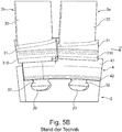
- forms a known from the prior art blade 3a, 3b each have an overhang 310 for encircling the radially outer edge 43 of the backup plate 4, which is formed over a total length L along the circumferential direction U a continuous rectilinear or circular arc extending edge 311 ,
- their respective overhangs 310 of adjoining edges 311 should be aligned with one another on a pair of adjacent blades 3a and 3b, so that the radially inner lower edges of these edges 311 lie on a circular path about the axis of rotation M of the rotor.
- FIGS. 5B and 5C illustrate.
- the individual overhangs 310 of mutually adjacent rotor blades 3a, 3b are offset radially relative to one another.
- the FIGS. 5B and 5C Here, by way of example, in each case an offset g of the two rotor blades 3a and 3b in the region of their overhangs 310.
- one (left) blade 3b is offset radially inward of the adjacent (right) blade 3a.
- the one overhang 310 of the one blade 3b thus projects into an annular gap flow in the circumferential direction U (offset "into wind”).
- one (left) blade 3b is offset radially outward of the other (right) blade 3a ("out of wind” offset).
- the edge 311 of the overhang 310 of the one blade 3b is thus completely offset radially outwards relative to the overhang 310 of the other blade 3a.
- the invention has for its object to improve a rotor in this regard.
- a rotor with a specially designed overhang is proposed on at least one blade that is positively connected to the rotor base part.
- the overhang along its extent in the circumferential direction at least one edge portion which surrounds a (radially outer) edge of the securing element and at a radially inner lower edge of the overhang against at least one further, the edge of the securing element also encompassing edge portion of the overhang in radially outside pointing direction is withdrawn.
- the overhang of at least one rotor blade in a rotor according to the invention is retracted or reset at a lower edge of the overhang in a radially outward direction such that the overhang at a radially inner lower edge does not have a rectilinear or arcuate course along the circumferential direction.
- This includes in particular the formation of an edge portion with radial offset to an adjacent edge portion of the same overhang as well as the formation of an edge portion whose radial extent steadily decreases in the circumferential direction and thus defines an obliquely extending to the circumferential direction portion of the lower edge of the overhang.
- a radially inner lower edge of an overhang are therefore for example radially offset from each other and / or at an angle to each other extending areas formed. It is thus from the outset a return, preferably defined in the area of adjacent overhangs. This can lead, in particular with appropriate dimensioning, to minimizing or avoiding disturbing turbulences in the area of the securing element.
- a reduction in weight can be achieved as well as a simplification in the assembly and / or disassembly of a blade, the latter by the at least one recessed edge portion may be formed and arranged along the circumferential direction, that at least a portion of the overhang are pushed through in the axial direction by the mounting groove can, if the fuse element is not or no longer fixed to the rotor base part.
- the at least one radially outwardly recessed edge portion may have a smaller extent in the radially inward direction than an adjacent edge portion.
- the overhang thus extends less strongly radially inward in the region of the recessed edge portion.
- the at least one radially outwardly recessed edge portion is provided in an embodiment at a circumferential end of the overhang. In this way, a defined recess is provided on the recessed edge portion in that area at the adjacent two adjacent blades with their blade bases.
- the at least one radially outwardly recessed edge portion forms in one embodiment, an area on the radially inner lower edge of the overhang, which extends at least partially inclined to the circumferential direction.
- the withdrawn edge portion can consequently not only be stepped back to an adjoining edge portion of the overhang, but also form a recess that increases or decreases at least in sections in the circumferential direction.
- an embodiment provides that extends the at least one radially recessed edge portion with a length along the circumferential direction of the rotor, which corresponds to at least three times, in a variant at least four times a height, with the radially withdrawn radially outward Edge portion opposite an adjacent edge portion of the overhang (at least) is withdrawn.
- the at least one radially outwardly recessed edge portion opposite an adjacent edge portion of the blade overhang is retracted at least by a height of 0.5 mm, in particular at least by a height of 0.8 mm or 1 mm. It is thus formed on the recessed edge portion a return, which has a maximum depth of at least 0.5 mm, 0.8 mm or 1 mm with nominal alignment of two adjacent blades.
- the overhang of a blade of the rotor can have two edge sections, namely a first and a second edge section, which are each retracted in a radially outward-facing direction relative to at least one further third edge section of the overhang which likewise encompasses the edge of the securing element.
- the first edge portion and the second edge portion are thus spatially separated from each other along the circumferential direction and spaced from each other, but each withdrawn radially outward relative to at least a third edge portion of the blade overhang.
- the two recessed edge portions can be withdrawn to different degrees and / or extend along the circumferential direction with mutually different lengths.
- the overhang of a blade can thus be designed asymmetrically with respect to a radial direction. This allows, for example, a direction of rotation optimized design of a return, which is formed by two adjoining and each radially recessed edge portions of two adjacent blades.
- first and second radially outwardly recessed edge portions of a blade are provided along mutually circumferentially spaced ends of the associated overhang (and a blade base of the associated blade).
- a second edge portion of a (first) blade overhang and a first edge portion of another (second) blade overhang abut each other.
- At least one of the first and second radially outwardly recessed edge portions opposite the adjacent third edge portion of the blade overhang is at least the sum of the shape and Position tolerances of this third edge section withdrawn.
- a return is formed by a withdrawn first or second edge portion, which has a maximum (radial) depth of at least the sum of the shape and position tolerances of the third edge portion with nominal alignment of two adjacent blades.
- About the shape and position tolerances while a nominal position of the third edge portion with respect to the associated mounting groove and / or with respect to an overhang of an adjacent blade of the rotor is predetermined.
- a return defined in the area of the blade bases of two adjacent rotor blades is in this case, for example, elliptical, trapezoidal or triangular in a view along the axis of rotation.
- overhangs with adjoining and respectively radially outwardly recessed edge sections may be provided on each pair of adjacent rotor blades, so that a radially outwardly directed return of defined minimum length and minimum height along the circumferential direction in the region of adjoining edge sections of two adjacent blades is formed.
- the formation of a return is thus not limited to individual pairs of blades in this variant, but provided throughout in each area of two adjacent blades.
- the at least one radially outwardly recessed edge portion may be made for example by mechanical material removal. This includes manufacturing by a machining process such as grinding or milling. In such a variant, consequently, material can be removed, for example abraded, on the overhang of a blade base in order to achieve that a radially inner lower edge of the overhang no longer has a straight course.
- a radially outwardly recessed edge portion may be made by thermal removal of material.
- the production takes place by means of erosion.
- the (thermal) Material removal on the overhang to produce a recessed edge portion in a single operation with the production of certain functional areas on a blade occurs.
- a functional area such as a damper pocket or a blade base area provided to reduce weight with at least one recess, to be machined on a blade in the area of the blade base by erosion. In such an operation, the overhang of a blade can then be processed accordingly to provide a radially recessed edge portion thereto.
- the at least one securing element can be provided for the axial securing of at least two moving blades.
- a preferably plate-shaped securing element is encompassed on a (radially outer) edge of the overhangs of at least two blades.
- FIG. 6 illustrates schematically and in section a (gas turbine) engine T, in which the individual engine components along a central axis or axis of rotation M are arranged one behind the other.
- a fan F At an inlet or intake E of the engine T, air is sucked in along an entrance direction E by means of a fan F.
- This fan F is driven by a shaft that is rotated by a turbine TT.
- the turbine TT adjoins a compressor V, which has, for example, a low-pressure compressor 11 and a high-pressure compressor 12, and possibly also a medium-pressure compressor.
- the fan F supplies air to the compressor V and, on the other hand, a bypass channel B for generating the thrust.
- the conveyed via the compressor V air finally enters a combustion chamber portion BK in which the driving power for driving the turbine TT is generated.
- the turbine TT has a high-pressure turbine 13, a medium-pressure turbine 14 and a low-pressure turbine 15.
- the turbine TT activates the fan F via the energy released during combustion, in order to then generate the required thrust via the air conveyed into the bypass duct B.
- the air in this case leaves the bypass passage B in the region of an outlet A at the end of the engine T, at which the exhaust gases flow out of the turbine TT to the outside.
- the outlet A in this case usually has a discharge nozzle.
- the rotor is arranged and rotatably mounted about the central axis or rotation axis M such that the individual securing plates 4 provided along the circumferential direction U for the axial securing of the rotor blades 3a, 3b are arranged on a downstream end side of the rotor 2.
- the individual securing elements 4 are thus facing an annular space 5, which is formed in the region of the blade roots 32 of the individual moving blades 3a, 3b between the rotor and a guide blade arrangement 6.
- the flow arising in this annular space 5 can - as explained in the introduction - be undesirably swirled in a configuration of the overhangs 310 of the blade bases 31 used for the connection between the rotor blades 3 a, 3 b and a securing element 4 if individual overhangs 310 are offset from each other due to tolerances. Then, individual overhangs 31 project completely into the flow path defined annularly around the axis of rotation along the securing plates 4 or are set back radially outward for this purpose (cf. FIGS. 5B and 5C ).
- an overhang 310 which is provided for the positive connection with a radially outer edge 43 of a multipart or one-part securing element, such as a securing plate 4, is formed with a rim section of defined geometry and size taken back in the radially outer direction ra.
- At least one defined radial return is provided from the outset, the flow as little as possible, but in predictably influenced in every case.
- a plurality of recesses distributed along the circumferential direction U are provided, in particular on each pair of blade bases 31 arranged adjacent to one another.
- an overhang 310 of a blade base 31 of each blade 3a, 3b fixed to the rotor base 2 has two edge portions 311a and 311c recessed radially outward. These two radially recessed edge portions 311 a and 311 c have a smaller extent in radially inward direction ri than a third edge portion 311 b formed between them.
- the length of the third edge portion 311 b along the circumferential direction U may be at least twice the shape and position tolerances of a gap between the axial securing elements 4 and / or at least half of a minimum width d of a blade neck 320 of the blade root 32 inserted into the associated fastening groove 20 a blade 3a or 3b (see the detail of a blade 3a of FIG. 1 D) ,
- the length of the third edge portion 311 b along the circumferential direction U makes up less than 60%, possibly less than 50% or even less than 35% of the total length L of an overhang 310 along the circumferential direction U.
- each a recessed edge portions 311 a or 311 c is provided at the along the circumferential direction U spaced ends of an overhang 310 .
- the edge portions 311a and 311c extend with different lengths a1 and a2 in the circumferential direction U. Both recessed edge portions 311a and 311c further form an inclined to the circumferential direction U extending portion of the lower edge of the overhang 310 from.
- Each recessed edge portion 311a, 311c extends obliquely outward from the middle, third edge portion 311b to the respective end, so that a radial extension of the respective recessed edge portion 311a or 311c steadily decreases towards the respective lateral edge of the overhang 310.
- the individual edge portions 311a and 311c are each withdrawn up to a height b1 or b2 relative to the central edge portion 311b.
- This height b1 or b2 is present greater than 0.8 mm and is about 1 mm.
- the extension in the circumferential direction U of the respective withdrawn edge section 311a, 311c is measured as a multiple of this height b1 or b2, preferably an integer.
- a length a1, a2 corresponds to at least three times a height b1 or b2 of the respective withdrawn edge section 311 a, 311 c.
- the heights b1 and b2 of the recessed edge portions 311a and 311c are dimensioned so that in the region of mutually adjacent blades 3a, 3b and thus adjacent blade bases 31 by two obliquely converging recessed edge portions 311c and 311a each have a radial recess 33 in Course of the successive in the circumferential direction U lower edges of a plurality of locking plates 4 is formed.
- This radial recess 33 is on the recessed edge portions 311 c and 311 a of the individual blades 3a and 3b dimensioned so that even with a tolerance-related maximum radial offset g two blades 3a and 3b, a radial depth of the respective recess 33 is greater than the offset g and preferably equal to a multiple of the offset g.
- a (relevant) flow influence due to the offset g is excluded or minimal (cf. FIG. 1 B) ,
- the recessed edge portions 311a and 311c still provide sufficient extension of the overhang 310 in the radially inner direction ri, so that a groove 3100 for the engaged radially outer edge 43 of the securing plate 4 is also present in the region of a recessed edge portion 311a or 311c.
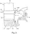
- the radially inner edge 42 of a securing plate 4 is accommodated in a groove 2100 of the rotor base part 2, which is formed by a protrusion 210 projecting in the radially outer direction ra.
- the securing plate 4 ensures that the individual moving blades 3a, 3b are axially secured to the rotor base part 2 in the region of their respective blade root 32, which is at least partially covered by a securing plate 4 (see also FIG FIG. 3 ).
- edge portion 311 b of the overhang 310 further extends only radially in the region in which the mounting groove 20 is located.
- the radially inwardly further projecting edge portion 311b is dimensioned such that the blade root 32 can be pushed in the axial direction through the fastening groove 20 and the gap thus defined between two webs 22 of the rotor base part 2, if the securing plate 4 is not or no longer attached is. This is at an overhang of constant radial extent corresponding to FIG. 5D not possible.
- the overhang 310 can over the other opposite, a fastening groove 20 laterally bordered webs 22 of the rotor base part 2 are not pushed past.
- the radial extent of the blade root 32 and thus the length of a blade neck 320 would have to be increased so that a lower edge of the overhang 310 extends radially further outward than the ends of the webs 22 but an increase in the weight of a blade 3a, 3b accompanied.
- the additional installation advantage can be realized in the illustrated embodiment of a solution according to the invention without weight disadvantage.
- An overhang 310 on a blade base 31 is here profiled, so that the two along the circumferential direction U spaced edge portions 311 a and 311 b of a blade 3a or 3b in the radially outer direction ra relative to the middle, third edge portion 311b of the overhang 310 of the respective blade 3a or 3b are designed to spring back radially.
- the individual recessed edge portions 311a and 311c each have areas of constant radial extent along the circumferential direction U.
- each of the recessed edge portions 311 a, 311c of a blade of the FIGS. 2A and 2 B at least one area at which a height of the respective recessed edge portion 311a, 311c in the circumferential direction U or opposite thereto does not decrease.
- a recess 33 defined in the area of the blade bases 31 of two adjacent moving blades 3a, 3b in the view along the axis of rotation of the FIG. 2 is trapezoidal, while the return 33 in the variant of FIGS. 1A to 1C is triangular.
- the return 33 in the variant of FIGS. 1A to 1C is triangular.
- a more rounded course of the lower edges of the recessed edge portions 311a, 311c can be formed in a possible development also an elliptical recess.
- a machining process or a thermal removal of material may be provided for the production of the recessed edge portions 311a, 311c on a moving blade 3a or 3b.
- a machining process or a thermal removal of material may be provided for the production of the recessed edge portions 311a, 311c on a moving blade 3a or 3b.
- the recessed edge portions 311a and 311c in the embodiment of FIGS. 1A to 1C be made comparatively easy by grinding.
- the production of the recessed edge portions 311 a and 311 c in one operation with (not shown here) damper pockets or other functional areas on the blades 3a, 3b are made, which are usually also produced by erosion.
- FIG. 2B is in accordance with the Figure 1C even with partial suppression of the backup plate 4 illustrates that even in this embodiment by the withdrawn edge portions 311 a and 311 c of the overhang 310 does not block a pushing through the blade root 32 in the axial direction by a mounting groove 20.
- the radially inwardly further projecting (middle) edge portion 311 b is dimensioned so that it fits at the upper end of the fastening groove 20 through the defined between two webs 22 of the rotor base part 2 gap.
- the securing plate 4 has a central region 40 lying between the radially inner and radially outer edges 42 and 43. From the FIG. 4 In particular, it can be seen how a radially outer edge 43 of the locking plate 4 is received in the groove 3100 of the blade base 31 of a blade 3b and encompassed by the radially inwardly extending overhang 310, while the central region 40 is outside the groove 3100 along the blade root 32 extends.
Landscapes
- Engineering & Computer Science (AREA)
- Mechanical Engineering (AREA)
- General Engineering & Computer Science (AREA)
- Structures Of Non-Positive Displacement Pumps (AREA)
Applications Claiming Priority (1)
| Application Number | Priority Date | Filing Date | Title |
|---|---|---|---|
| DE102016107315.6A DE102016107315A1 (de) | 2016-04-20 | 2016-04-20 | Rotor mit Überhang an Laufschaufeln für ein Sicherungselement |
Publications (2)
| Publication Number | Publication Date |
|---|---|
| EP3236011A1 true EP3236011A1 (fr) | 2017-10-25 |
| EP3236011B1 EP3236011B1 (fr) | 2022-08-31 |
Family
ID=58549064
Family Applications (1)
| Application Number | Title | Priority Date | Filing Date |
|---|---|---|---|
| EP17166817.1A Active EP3236011B1 (fr) | 2016-04-20 | 2017-04-18 | Rotor comprenant un porte à faux sur les pales pour un élément de sécurité |
Country Status (3)
| Country | Link |
|---|---|
| US (1) | US10526904B2 (fr) |
| EP (1) | EP3236011B1 (fr) |
| DE (1) | DE102016107315A1 (fr) |
Families Citing this family (4)
| Publication number | Priority date | Publication date | Assignee | Title |
|---|---|---|---|---|
| CN109162763B (zh) * | 2018-09-10 | 2021-05-18 | 东方电气集团东方汽轮机有限公司 | 一种菌形叶根锁口结构 |
| US10704400B2 (en) * | 2018-10-17 | 2020-07-07 | Pratt & Whitney Canada Corp. | Rotor assembly with rotor disc lip |
| US11168615B1 (en) | 2020-08-25 | 2021-11-09 | Raytheon Technologies Corporation | Double ring axial sealing design |
| KR102454379B1 (ko) * | 2020-09-08 | 2022-10-14 | 두산에너빌리티 주식회사 | 로터 및 이를 포함하는 터보머신 |
Citations (5)
| Publication number | Priority date | Publication date | Assignee | Title |
|---|---|---|---|---|
| GB2258273A (en) * | 1991-08-02 | 1993-02-03 | Ruston Gas Turbines Ltd | Rotor blade locking arrangement. |
| US5256035A (en) | 1992-06-01 | 1993-10-26 | United Technologies Corporation | Rotor blade retention and sealing construction |
| US20090116965A1 (en) * | 2005-09-07 | 2009-05-07 | Dieter Brillert | Arrangement for axially securing rotating blades in a rotor, sealing element for such an arangement, and use of such an arrangement |
| EP2860350A1 (fr) * | 2013-10-10 | 2015-04-15 | Siemens Aktiengesellschaft | Aube de turbine et turbine à gaz |
| EP2873807A1 (fr) * | 2013-11-18 | 2015-05-20 | Siemens Aktiengesellschaft | Plaque de recouvrement, aube mobile, disque de roue, boulon et turbine à gaz |
Family Cites Families (28)
| Publication number | Priority date | Publication date | Assignee | Title |
|---|---|---|---|---|
| GB699582A (en) * | 1950-11-14 | 1953-11-11 | Rolls Royce | Improvements in or relating to gas-turbine engines |
| GB928349A (en) * | 1960-12-06 | 1963-06-12 | Rolls Royce | Improvements in or relating to bladed rotors of fluid flow machines |
| NL295165A (fr) * | 1962-07-11 | |||
| US3501249A (en) * | 1968-06-24 | 1970-03-17 | Westinghouse Electric Corp | Side plates for turbine blades |
| GB1291302A (en) * | 1970-03-14 | 1972-10-04 | Sec Dep For Defendence | Improvements in bladed rotor assemblies |
| US3656865A (en) * | 1970-07-21 | 1972-04-18 | Gen Motors Corp | Rotor blade retainer |
| US4648799A (en) * | 1981-09-22 | 1987-03-10 | Westinghouse Electric Corp. | Cooled combustion turbine blade with retrofit blade seal |
| US4480958A (en) * | 1983-02-09 | 1984-11-06 | The United States Of America As Represented By The Secretary Of The Air Force | High pressure turbine rotor two-piece blade retainer |
| FR2812906B1 (fr) * | 2000-08-10 | 2002-09-20 | Snecma Moteurs | Bague de retention axiale d'un flasque sur un disque |
| KR100928176B1 (ko) * | 2003-02-19 | 2009-11-25 | 알스톰 테크놀러지 리미티드 | 특히 가스 터빈의 블레이드 세그먼트에 사용되는 실링 장치 |
| GB0503676D0 (en) | 2005-02-23 | 2005-03-30 | Rolls Royce Plc | A lock plate arrangement |
| EP1916382A1 (fr) * | 2006-10-25 | 2008-04-30 | Siemens AG | Dispositif et procédé pour sécuriser un élément d'étanchéité sur un rotor |
| EP1916389A1 (fr) * | 2006-10-26 | 2008-04-30 | Siemens Aktiengesellschaft | Assemblage d'aubes de turbine |
| EP1944471B1 (fr) * | 2007-01-09 | 2009-09-02 | Siemens Aktiengesellschaft | Partie axiale d'une rotor de turbine |
| US7566201B2 (en) * | 2007-01-30 | 2009-07-28 | Siemens Energy, Inc. | Turbine seal plate locking system |
| FR2939832B1 (fr) | 2008-12-11 | 2011-01-07 | Turbomeca | Roue de turbine equipee d'un dispositif de retenue axiale verrouillant des pales par rapport a un disque. |
| EP2239419A1 (fr) * | 2009-03-31 | 2010-10-13 | Siemens Aktiengesellschaft | Rotor de turbomachine axiale doté d'un disque d'étanchéité |
| EP2964894B1 (fr) * | 2013-03-05 | 2019-04-10 | Rolls-Royce North American Technologies, Inc. | Procédé de rétention de plaques de capot segmentées de turbine |
| JP5358031B1 (ja) * | 2013-03-22 | 2013-12-04 | 三菱重工業株式会社 | タービンロータ、タービン、及びシール板の取外方法 |
| US9416662B2 (en) * | 2013-09-03 | 2016-08-16 | General Electric Company | Method and system for providing cooling for turbine components |
| US9732617B2 (en) * | 2013-11-26 | 2017-08-15 | General Electric Company | Cooled airfoil trailing edge and method of cooling the airfoil trailing edge |
| US9506365B2 (en) * | 2014-04-21 | 2016-11-29 | Honeywell International Inc. | Gas turbine engine components having sealed stress relief slots and methods for the fabrication thereof |
| US9970319B2 (en) * | 2014-05-05 | 2018-05-15 | United Technologies Corporation | Reducing variation in cooling hole meter length |
| US10006364B2 (en) * | 2014-08-20 | 2018-06-26 | United Technologies Corporation | Gas turbine rotors |
| GB201417039D0 (en) * | 2014-09-26 | 2014-11-12 | Rolls Royce Plc | A bladed rotor arrangement and a lock plate for a bladed rotor arrangement |
| GB201417038D0 (en) * | 2014-09-26 | 2014-11-12 | Rolls Royce Plc | A bladed rotor arrangement |
| EP3034795B1 (fr) * | 2014-12-17 | 2019-02-27 | Ansaldo Energia Switzerland AG | Plaque de serrure avec rainures radiales |
| US9835032B2 (en) * | 2015-06-01 | 2017-12-05 | United Technologies Corporation | Disk lug cooling flow trenches |
-
2016
- 2016-04-20 DE DE102016107315.6A patent/DE102016107315A1/de not_active Withdrawn
-
2017
- 2017-04-18 US US15/490,242 patent/US10526904B2/en active Active
- 2017-04-18 EP EP17166817.1A patent/EP3236011B1/fr active Active
Patent Citations (5)
| Publication number | Priority date | Publication date | Assignee | Title |
|---|---|---|---|---|
| GB2258273A (en) * | 1991-08-02 | 1993-02-03 | Ruston Gas Turbines Ltd | Rotor blade locking arrangement. |
| US5256035A (en) | 1992-06-01 | 1993-10-26 | United Technologies Corporation | Rotor blade retention and sealing construction |
| US20090116965A1 (en) * | 2005-09-07 | 2009-05-07 | Dieter Brillert | Arrangement for axially securing rotating blades in a rotor, sealing element for such an arangement, and use of such an arrangement |
| EP2860350A1 (fr) * | 2013-10-10 | 2015-04-15 | Siemens Aktiengesellschaft | Aube de turbine et turbine à gaz |
| EP2873807A1 (fr) * | 2013-11-18 | 2015-05-20 | Siemens Aktiengesellschaft | Plaque de recouvrement, aube mobile, disque de roue, boulon et turbine à gaz |
Also Published As
| Publication number | Publication date |
|---|---|
| DE102016107315A1 (de) | 2017-10-26 |
| EP3236011B1 (fr) | 2022-08-31 |
| US20170306771A1 (en) | 2017-10-26 |
| US10526904B2 (en) | 2020-01-07 |
Similar Documents
| Publication | Publication Date | Title |
|---|---|---|
| EP2108784B1 (fr) | Turbomachine dotée d'un composant d'injecteur de fluide | |
| EP2179143B1 (fr) | Refroidissement de fente entre une paroi de chambre de combustion et une paroi de turbine d'une installation de turbine à gaz | |
| EP3236011B1 (fr) | Rotor comprenant un porte à faux sur les pales pour un élément de sécurité | |
| EP1656493A1 (fr) | Anneau de fixation segmente pour une turbine | |
| EP2132414B1 (fr) | Agencement en feuillure | |
| EP1460237A1 (fr) | Carter pour une turbosoufflante | |
| DE102015219556A1 (de) | Diffusor für Radialverdichter, Radialverdichter und Turbomaschine mit Radialverdichter | |
| EP2918778B1 (fr) | Procédé de dimensionnement d'une turbine | |
| WO2015197536A1 (fr) | Diffuseur pour compresseur radial | |
| EP2818724B1 (fr) | Turbomachine et procédé | |
| EP2921778A1 (fr) | Chambre de combustion d'une turbine à gaz | |
| EP3064706A1 (fr) | Rangée d'aubes directrices pour une turbomachine traversée axialement | |
| EP3336313A1 (fr) | Ensemble d'aube mobile pour turbines d'une turbine turbine à gaz et procédé de fourniture d'air sceau dans un ensemble d'aube mobile pour turbines | |
| EP2846000B1 (fr) | Roue statorique d'une turbine à gaz | |
| EP3428393B1 (fr) | Roue aubagée d'une turbomachine | |
| EP3287611B1 (fr) | Turbine à gaz | |
| EP3078808A1 (fr) | Rangée d'aubes pour une turbomachine | |
| EP3022393B1 (fr) | Rotor pour une turbomachine thermique | |
| EP3431708A1 (fr) | Dispositif d'écoulement autour, turbomachine et application associées | |
| EP3309359B1 (fr) | Ensemble d'aubes mobiles pour un moteur à turbine à gaz | |
| EP2808557A1 (fr) | Ensemble structurel pour une turbomachine | |
| DE102012215413B4 (de) | Baugruppe einer Axialturbomaschine | |
| EP3321589B1 (fr) | Buse de carburant d'une turbine à gaz dotée du générateur de tourbillons | |
| EP2808558B1 (fr) | Ensemble structurel pour une turbomachine | |
| EP3109520A1 (fr) | Support d'étanchéité, stator et turbomachine |
Legal Events
| Date | Code | Title | Description |
|---|---|---|---|
| PUAI | Public reference made under article 153(3) epc to a published international application that has entered the european phase |
Free format text: ORIGINAL CODE: 0009012 |
|
| STAA | Information on the status of an ep patent application or granted ep patent |
Free format text: STATUS: THE APPLICATION HAS BEEN PUBLISHED |
|
| AK | Designated contracting states |
Kind code of ref document: A1 Designated state(s): AL AT BE BG CH CY CZ DE DK EE ES FI FR GB GR HR HU IE IS IT LI LT LU LV MC MK MT NL NO PL PT RO RS SE SI SK SM TR |
|
| AX | Request for extension of the european patent |
Extension state: BA ME |
|
| STAA | Information on the status of an ep patent application or granted ep patent |
Free format text: STATUS: REQUEST FOR EXAMINATION WAS MADE |
|
| 17P | Request for examination filed |
Effective date: 20180425 |
|
| RBV | Designated contracting states (corrected) |
Designated state(s): AL AT BE BG CH CY CZ DE DK EE ES FI FR GB GR HR HU IE IS IT LI LT LU LV MC MK MT NL NO PL PT RO RS SE SI SK SM TR |
|
| STAA | Information on the status of an ep patent application or granted ep patent |
Free format text: STATUS: EXAMINATION IS IN PROGRESS |
|
| 17Q | First examination report despatched |
Effective date: 20190613 |
|
| STAA | Information on the status of an ep patent application or granted ep patent |
Free format text: STATUS: EXAMINATION IS IN PROGRESS |
|
| STAA | Information on the status of an ep patent application or granted ep patent |
Free format text: STATUS: EXAMINATION IS IN PROGRESS |
|
| GRAP | Despatch of communication of intention to grant a patent |
Free format text: ORIGINAL CODE: EPIDOSNIGR1 |
|
| STAA | Information on the status of an ep patent application or granted ep patent |
Free format text: STATUS: GRANT OF PATENT IS INTENDED |
|
| INTG | Intention to grant announced |
Effective date: 20220315 |
|
| GRAJ | Information related to disapproval of communication of intention to grant by the applicant or resumption of examination proceedings by the epo deleted |
Free format text: ORIGINAL CODE: EPIDOSDIGR1 |
|
| STAA | Information on the status of an ep patent application or granted ep patent |
Free format text: STATUS: EXAMINATION IS IN PROGRESS |
|
| GRAP | Despatch of communication of intention to grant a patent |
Free format text: ORIGINAL CODE: EPIDOSNIGR1 |
|
| STAA | Information on the status of an ep patent application or granted ep patent |
Free format text: STATUS: GRANT OF PATENT IS INTENDED |
|
| INTC | Intention to grant announced (deleted) | ||
| INTG | Intention to grant announced |
Effective date: 20220525 |
|
| GRAS | Grant fee paid |
Free format text: ORIGINAL CODE: EPIDOSNIGR3 |
|
| GRAA | (expected) grant |
Free format text: ORIGINAL CODE: 0009210 |
|
| STAA | Information on the status of an ep patent application or granted ep patent |
Free format text: STATUS: THE PATENT HAS BEEN GRANTED |
|
| AK | Designated contracting states |
Kind code of ref document: B1 Designated state(s): AL AT BE BG CH CY CZ DE DK EE ES FI FR GB GR HR HU IE IS IT LI LT LU LV MC MK MT NL NO PL PT RO RS SE SI SK SM TR |
|
| REG | Reference to a national code |
Ref country code: CH Ref legal event code: EP Ref country code: GB Ref legal event code: FG4D Free format text: NOT ENGLISH |
|
| REG | Reference to a national code |
Ref country code: AT Ref legal event code: REF Ref document number: 1515429 Country of ref document: AT Kind code of ref document: T Effective date: 20220915 Ref country code: DE Ref legal event code: R096 Ref document number: 502017013695 Country of ref document: DE |
|
| REG | Reference to a national code |
Ref country code: IE Ref legal event code: FG4D Free format text: LANGUAGE OF EP DOCUMENT: GERMAN |
|
| REG | Reference to a national code |
Ref country code: LT Ref legal event code: MG9D |
|
| REG | Reference to a national code |
Ref country code: NL Ref legal event code: MP Effective date: 20220831 |
|
| PG25 | Lapsed in a contracting state [announced via postgrant information from national office to epo] |
Ref country code: SE Free format text: LAPSE BECAUSE OF FAILURE TO SUBMIT A TRANSLATION OF THE DESCRIPTION OR TO PAY THE FEE WITHIN THE PRESCRIBED TIME-LIMIT Effective date: 20220831 Ref country code: RS Free format text: LAPSE BECAUSE OF FAILURE TO SUBMIT A TRANSLATION OF THE DESCRIPTION OR TO PAY THE FEE WITHIN THE PRESCRIBED TIME-LIMIT Effective date: 20220831 Ref country code: NO Free format text: LAPSE BECAUSE OF FAILURE TO SUBMIT A TRANSLATION OF THE DESCRIPTION OR TO PAY THE FEE WITHIN THE PRESCRIBED TIME-LIMIT Effective date: 20221130 Ref country code: LV Free format text: LAPSE BECAUSE OF FAILURE TO SUBMIT A TRANSLATION OF THE DESCRIPTION OR TO PAY THE FEE WITHIN THE PRESCRIBED TIME-LIMIT Effective date: 20220831 Ref country code: LT Free format text: LAPSE BECAUSE OF FAILURE TO SUBMIT A TRANSLATION OF THE DESCRIPTION OR TO PAY THE FEE WITHIN THE PRESCRIBED TIME-LIMIT Effective date: 20220831 Ref country code: FI Free format text: LAPSE BECAUSE OF FAILURE TO SUBMIT A TRANSLATION OF THE DESCRIPTION OR TO PAY THE FEE WITHIN THE PRESCRIBED TIME-LIMIT Effective date: 20220831 Ref country code: ES Free format text: LAPSE BECAUSE OF FAILURE TO SUBMIT A TRANSLATION OF THE DESCRIPTION OR TO PAY THE FEE WITHIN THE PRESCRIBED TIME-LIMIT Effective date: 20220831 |
|
| PG25 | Lapsed in a contracting state [announced via postgrant information from national office to epo] |
Ref country code: PL Free format text: LAPSE BECAUSE OF FAILURE TO SUBMIT A TRANSLATION OF THE DESCRIPTION OR TO PAY THE FEE WITHIN THE PRESCRIBED TIME-LIMIT Effective date: 20220831 Ref country code: IS Free format text: LAPSE BECAUSE OF FAILURE TO SUBMIT A TRANSLATION OF THE DESCRIPTION OR TO PAY THE FEE WITHIN THE PRESCRIBED TIME-LIMIT Effective date: 20221231 Ref country code: HR Free format text: LAPSE BECAUSE OF FAILURE TO SUBMIT A TRANSLATION OF THE DESCRIPTION OR TO PAY THE FEE WITHIN THE PRESCRIBED TIME-LIMIT Effective date: 20220831 Ref country code: GR Free format text: LAPSE BECAUSE OF FAILURE TO SUBMIT A TRANSLATION OF THE DESCRIPTION OR TO PAY THE FEE WITHIN THE PRESCRIBED TIME-LIMIT Effective date: 20221201 |
|
| PG25 | Lapsed in a contracting state [announced via postgrant information from national office to epo] |
Ref country code: SM Free format text: LAPSE BECAUSE OF FAILURE TO SUBMIT A TRANSLATION OF THE DESCRIPTION OR TO PAY THE FEE WITHIN THE PRESCRIBED TIME-LIMIT Effective date: 20220831 Ref country code: RO Free format text: LAPSE BECAUSE OF FAILURE TO SUBMIT A TRANSLATION OF THE DESCRIPTION OR TO PAY THE FEE WITHIN THE PRESCRIBED TIME-LIMIT Effective date: 20220831 Ref country code: PT Free format text: LAPSE BECAUSE OF FAILURE TO SUBMIT A TRANSLATION OF THE DESCRIPTION OR TO PAY THE FEE WITHIN THE PRESCRIBED TIME-LIMIT Effective date: 20230102 Ref country code: DK Free format text: LAPSE BECAUSE OF FAILURE TO SUBMIT A TRANSLATION OF THE DESCRIPTION OR TO PAY THE FEE WITHIN THE PRESCRIBED TIME-LIMIT Effective date: 20220831 Ref country code: CZ Free format text: LAPSE BECAUSE OF FAILURE TO SUBMIT A TRANSLATION OF THE DESCRIPTION OR TO PAY THE FEE WITHIN THE PRESCRIBED TIME-LIMIT Effective date: 20220831 |
|
| PG25 | Lapsed in a contracting state [announced via postgrant information from national office to epo] |
Ref country code: SK Free format text: LAPSE BECAUSE OF FAILURE TO SUBMIT A TRANSLATION OF THE DESCRIPTION OR TO PAY THE FEE WITHIN THE PRESCRIBED TIME-LIMIT Effective date: 20220831 Ref country code: EE Free format text: LAPSE BECAUSE OF FAILURE TO SUBMIT A TRANSLATION OF THE DESCRIPTION OR TO PAY THE FEE WITHIN THE PRESCRIBED TIME-LIMIT Effective date: 20220831 |
|
| REG | Reference to a national code |
Ref country code: DE Ref legal event code: R026 Ref document number: 502017013695 Country of ref document: DE |
|
| PLBI | Opposition filed |
Free format text: ORIGINAL CODE: 0009260 |
|
| PLAB | Opposition data, opponent's data or that of the opponent's representative modified |
Free format text: ORIGINAL CODE: 0009299OPPO |
|
| PLAX | Notice of opposition and request to file observation + time limit sent |
Free format text: ORIGINAL CODE: EPIDOSNOBS2 |
|
| PG25 | Lapsed in a contracting state [announced via postgrant information from national office to epo] |
Ref country code: NL Free format text: LAPSE BECAUSE OF FAILURE TO SUBMIT A TRANSLATION OF THE DESCRIPTION OR TO PAY THE FEE WITHIN THE PRESCRIBED TIME-LIMIT Effective date: 20220831 Ref country code: AL Free format text: LAPSE BECAUSE OF FAILURE TO SUBMIT A TRANSLATION OF THE DESCRIPTION OR TO PAY THE FEE WITHIN THE PRESCRIBED TIME-LIMIT Effective date: 20220831 |
|
| 26 | Opposition filed |
Opponent name: CHAILLOT, DENIS Effective date: 20230531 |
|
| P01 | Opt-out of the competence of the unified patent court (upc) registered |
Effective date: 20230528 |
|
| R26 | Opposition filed (corrected) |
Opponent name: CHAILLOT, DENIS Effective date: 20230531 |
|
| PG25 | Lapsed in a contracting state [announced via postgrant information from national office to epo] |
Ref country code: SI Free format text: LAPSE BECAUSE OF FAILURE TO SUBMIT A TRANSLATION OF THE DESCRIPTION OR TO PAY THE FEE WITHIN THE PRESCRIBED TIME-LIMIT Effective date: 20220831 |
|
| PLBB | Reply of patent proprietor to notice(s) of opposition received |
Free format text: ORIGINAL CODE: EPIDOSNOBS3 |
|
| PLBP | Opposition withdrawn |
Free format text: ORIGINAL CODE: 0009264 |
|
| REG | Reference to a national code |
Ref country code: CH Ref legal event code: PL |
|
| PLAY | Examination report in opposition despatched + time limit |
Free format text: ORIGINAL CODE: EPIDOSNORE2 |
|
| GBPC | Gb: european patent ceased through non-payment of renewal fee |
Effective date: 20230418 |
|
| PG25 | Lapsed in a contracting state [announced via postgrant information from national office to epo] |
Ref country code: LU Free format text: LAPSE BECAUSE OF NON-PAYMENT OF DUE FEES Effective date: 20230418 |
|
| REG | Reference to a national code |
Ref country code: BE Ref legal event code: MM Effective date: 20230430 |
|
| PG25 | Lapsed in a contracting state [announced via postgrant information from national office to epo] |
Ref country code: MC Free format text: LAPSE BECAUSE OF FAILURE TO SUBMIT A TRANSLATION OF THE DESCRIPTION OR TO PAY THE FEE WITHIN THE PRESCRIBED TIME-LIMIT Effective date: 20220831 |
|
| PG25 | Lapsed in a contracting state [announced via postgrant information from national office to epo] |
Ref country code: GB Free format text: LAPSE BECAUSE OF NON-PAYMENT OF DUE FEES Effective date: 20230418 |
|
| PLBC | Reply to examination report in opposition received |
Free format text: ORIGINAL CODE: EPIDOSNORE3 |
|
| PG25 | Lapsed in a contracting state [announced via postgrant information from national office to epo] |
Ref country code: MC Free format text: LAPSE BECAUSE OF FAILURE TO SUBMIT A TRANSLATION OF THE DESCRIPTION OR TO PAY THE FEE WITHIN THE PRESCRIBED TIME-LIMIT Effective date: 20220831 Ref country code: LI Free format text: LAPSE BECAUSE OF NON-PAYMENT OF DUE FEES Effective date: 20230430 Ref country code: GB Free format text: LAPSE BECAUSE OF NON-PAYMENT OF DUE FEES Effective date: 20230418 Ref country code: CH Free format text: LAPSE BECAUSE OF NON-PAYMENT OF DUE FEES Effective date: 20230430 |
|
| REG | Reference to a national code |
Ref country code: IE Ref legal event code: MM4A |
|
| PG25 | Lapsed in a contracting state [announced via postgrant information from national office to epo] |
Ref country code: BE Free format text: LAPSE BECAUSE OF NON-PAYMENT OF DUE FEES Effective date: 20230430 |
|
| PG25 | Lapsed in a contracting state [announced via postgrant information from national office to epo] |
Ref country code: IE Free format text: LAPSE BECAUSE OF NON-PAYMENT OF DUE FEES Effective date: 20230418 |
|
| PG25 | Lapsed in a contracting state [announced via postgrant information from national office to epo] |
Ref country code: IE Free format text: LAPSE BECAUSE OF NON-PAYMENT OF DUE FEES Effective date: 20230418 |
|
| PG25 | Lapsed in a contracting state [announced via postgrant information from national office to epo] |
Ref country code: IT Free format text: LAPSE BECAUSE OF FAILURE TO SUBMIT A TRANSLATION OF THE DESCRIPTION OR TO PAY THE FEE WITHIN THE PRESCRIBED TIME-LIMIT Effective date: 20220831 |
|
| REG | Reference to a national code |
Ref country code: AT Ref legal event code: MM01 Ref document number: 1515429 Country of ref document: AT Kind code of ref document: T Effective date: 20230418 |
|
| PGFP | Annual fee paid to national office [announced via postgrant information from national office to epo] |
Ref country code: DE Payment date: 20240429 Year of fee payment: 8 |
|
| PG25 | Lapsed in a contracting state [announced via postgrant information from national office to epo] |
Ref country code: AT Free format text: LAPSE BECAUSE OF NON-PAYMENT OF DUE FEES Effective date: 20230418 |
|
| PG25 | Lapsed in a contracting state [announced via postgrant information from national office to epo] |
Ref country code: AT Free format text: LAPSE BECAUSE OF NON-PAYMENT OF DUE FEES Effective date: 20230418 |
|
| PGFP | Annual fee paid to national office [announced via postgrant information from national office to epo] |
Ref country code: FR Payment date: 20240430 Year of fee payment: 8 |