EP2964894B1 - Procédé de rétention de plaques de capot segmentées de turbine - Google Patents
Procédé de rétention de plaques de capot segmentées de turbine Download PDFInfo
- Publication number
- EP2964894B1 EP2964894B1 EP13866502.1A EP13866502A EP2964894B1 EP 2964894 B1 EP2964894 B1 EP 2964894B1 EP 13866502 A EP13866502 A EP 13866502A EP 2964894 B1 EP2964894 B1 EP 2964894B1
- Authority
- EP
- European Patent Office
- Prior art keywords
- disc
- cover plate
- segmented
- groove
- turbine
- Prior art date
- Legal status (The legal status is an assumption and is not a legal conclusion. Google has not performed a legal analysis and makes no representation as to the accuracy of the status listed.)
- Not-in-force
Links
Images


Classifications
-
- F—MECHANICAL ENGINEERING; LIGHTING; HEATING; WEAPONS; BLASTING
- F01—MACHINES OR ENGINES IN GENERAL; ENGINE PLANTS IN GENERAL; STEAM ENGINES
- F01D—NON-POSITIVE DISPLACEMENT MACHINES OR ENGINES, e.g. STEAM TURBINES
- F01D5/00—Blades; Blade-carrying members; Heating, heat-insulating, cooling or antivibration means on the blades or the members
- F01D5/30—Fixing blades to rotors; Blade roots ; Blade spacers
- F01D5/3007—Fixing blades to rotors; Blade roots ; Blade spacers of axial insertion type
- F01D5/3015—Fixing blades to rotors; Blade roots ; Blade spacers of axial insertion type with side plates
-
- B—PERFORMING OPERATIONS; TRANSPORTING
- B23—MACHINE TOOLS; METAL-WORKING NOT OTHERWISE PROVIDED FOR
- B23P—METAL-WORKING NOT OTHERWISE PROVIDED FOR; COMBINED OPERATIONS; UNIVERSAL MACHINE TOOLS
- B23P15/00—Making specific metal objects by operations not covered by a single other subclass or a group in this subclass
- B23P15/04—Making specific metal objects by operations not covered by a single other subclass or a group in this subclass turbine or like blades from several pieces
-
- F—MECHANICAL ENGINEERING; LIGHTING; HEATING; WEAPONS; BLASTING
- F01—MACHINES OR ENGINES IN GENERAL; ENGINE PLANTS IN GENERAL; STEAM ENGINES
- F01D—NON-POSITIVE DISPLACEMENT MACHINES OR ENGINES, e.g. STEAM TURBINES
- F01D5/00—Blades; Blade-carrying members; Heating, heat-insulating, cooling or antivibration means on the blades or the members
- F01D5/30—Fixing blades to rotors; Blade roots ; Blade spacers
- F01D5/32—Locking, e.g. by final locking blades or keys
- F01D5/326—Locking of axial insertion type blades by other means
-
- F—MECHANICAL ENGINEERING; LIGHTING; HEATING; WEAPONS; BLASTING
- F05—INDEXING SCHEMES RELATING TO ENGINES OR PUMPS IN VARIOUS SUBCLASSES OF CLASSES F01-F04
- F05D—INDEXING SCHEME FOR ASPECTS RELATING TO NON-POSITIVE-DISPLACEMENT MACHINES OR ENGINES, GAS-TURBINES OR JET-PROPULSION PLANTS
- F05D2230/00—Manufacture
- F05D2230/60—Assembly methods
-
- Y—GENERAL TAGGING OF NEW TECHNOLOGICAL DEVELOPMENTS; GENERAL TAGGING OF CROSS-SECTIONAL TECHNOLOGIES SPANNING OVER SEVERAL SECTIONS OF THE IPC; TECHNICAL SUBJECTS COVERED BY FORMER USPC CROSS-REFERENCE ART COLLECTIONS [XRACs] AND DIGESTS
- Y10—TECHNICAL SUBJECTS COVERED BY FORMER USPC
- Y10T—TECHNICAL SUBJECTS COVERED BY FORMER US CLASSIFICATION
- Y10T29/00—Metal working
- Y10T29/49—Method of mechanical manufacture
- Y10T29/49316—Impeller making
- Y10T29/4932—Turbomachine making
- Y10T29/49321—Assembling individual fluid flow interacting members, e.g., blades, vanes, buckets, on rotary support member
Definitions
- An improved gas turbine engine and more particularly, a method and apparatus for retaining segmented cover plates to a bladed turbine disc in a gas turbine engine.
- gas turbine engines are for example known from US 5 622 475 .
- Gas turbine engines employ turbine rotors that have a rotor body as well as a plurality of rotor blades that rotate therewith.
- the rotor blades may be an integral part of the rotor body or they may be separately anchored by a blade root that is positioned in one or a plurality of axially extending grooves of the rotor body.
- Rotors that have blades that are integral to the rotor body have certain draw backs in view of their unitary design.
- some aerospace applications have preferred turbine rotors that have rotor blades that are individually anchored to the rotor body by employing axially extending grooves in the rotor body that are operable to receive the blade roots of the rotor blade.
- Retaining members known as cover plates have been employed to secure the rotor blades axially relative to the rotor body.
- a challenge with such designs is the ease of installing and then maintaining the rotor blades after they have been in service.
- Prior methods for retaining a gas turbine blade relative to the rotor or disc body utilize segmented cover plates that require slots to be cut into a groove of the rotor body to allow the cover plates to slide into place, or the blades must be staggered during assembly to create clearance. Slots in the rotor body groove can create high stress areas and my not be a helpful feature. Retention methods utilizing locking wires below the segmented cover plates require machined segmented cover plates which are heavier and more expensive than conventional formed sheet metal segmented cover plates.
- Segmented cover plates that are held in place by grooves in the bottom of the blade platforms use a locking wire which interfaces with a groove in the radially inward edge of the cover plates and a groove in the disc.
- This method requires machined segmented cover plates in order to create the groove for the locking wire. It would be helpful to provide an improved segment cover plate that is formed from sheet metal which is inexpensive and lighter than machined cover plates. A new method of installing the segmented cover plate for retaining a rotor blade axially relative to a rotor body would also be helpful.
- US20080181767 discloses a prior art cover plate.
- An improved method is disclosed to axially retain segmented cover plates in relation to a turbine disc using a segmented retainer ring.
- Segmented cover plates are provided which are retained at their radially outward edge by grooves in the underside of the blade platform.
- the cover plates are axially retained at their radially inward edge by retainer ring segments which are inserted below each cover plate segment in groove in the disc.
- Segmented cover plates known as smash plates are also used and they do not require retainer ring segments. This arrangement allows the segmented cover plates to be assembled with the bladed disc without cover plate loading slots in the disc or staggering the blades to create assembly clearance.
- the improved system allows the use of segmented cover plates in turbine configurations where it is not possible to stagger the blades to create assembly clearance.
- the improved system also avoids cover plate loading slots in the disc which can be high stress features.
- the improved system includes a method to axially retain segmented cover plates in relation to a turbine disc using a segmented retainer ring.
- Figure 1 illustrates a gas turbine engine 10, which includes a fan 12, an intermediate pressure compressor and a high pressure compressor, 14 and 16, a combustor 18, a high pressure turbine, an intermediate pressure turbine, and a low pressure turbine, 20 and 21 and 22, respectively.
- the high pressure compressor 16 is connected to a first rotor shaft 24 while the intermediate pressure compressor 14 is connected to a second rotor shaft 26 and the fan is connected to a third rotor shaft 42.
- the shafts extend axially and are parallel to a longitudinal center line axis 28.
- Ambient air 30 enters the fan 12 and is directed across a fan rotor 32 in an annular duct 34, which in part is circumscribed by fan case 36.
- the bypass airflow 38 provides engine thrust while the primary gas stream 40 is directed to the combustor 18 and the high pressure turbine 20.
- the gas turbine engine 10 includes an improved turbine segmented cover plate assembly 50 and method of installation for axially retaining turbine blades to a body of a turbine disc.
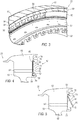
- FIG. 2 illustrates a front view of the low pressure turbine 22 assembly employing the improved turbine segmented cover plate assembly 50 along with the turbine blades and a turbine disc.
- the cover plate assembly 50 may be employed with the high pressure and intermediate pressure turbines, 20, 21.
- a discussion of the cover plate assembly 50 will be presented in the context of the low pressure turbine 22.
- the turbine 22 includes a disc 52 having a disc body 53, an annular groove 55 that circumscribes the body 53, a segmented retainer ring or clip 56 slideably positioned within the groove 55, a cover plate or locking member 58, smash plates 60, and turbine blades 62.
- Exemplary smash plates 60 are located at the 12 o'clock, 4 o'clock and 8 o'clock positions. It will be appreciate that more or less smash plates 60 may be used with the turbine 22 assembly and they may be positioned at alternative locations.
- the segmented ring(s) 56 are approximately the same length as the segmented cover plate(s).
- each cover plate 58 has a width encompassing about four blade plat forms 66, however the width could be more or less.
- the segmented cover plates 58 and segmented ring 54 are arcuate shaped in the side profile and have a similar geometric configuration and length.
- the disc body 53 of the turbine 22 includes a plurality of axially extending grooves 54 that are circumferentially spaced about the perimeter of the body 52.
- the grooves 54 are configured to receive a blade root 64 of each rotor blade 62.
- the blade root 64 leads into a blade platform 66 which in turns is the base in which the aerodynamic rotor blades (not shown) are supported.
- Each blade 62 is operable to slide axially relative to the corresponding axial groove 54, and they are axially retained in place by the combination of the retainer clip 56 and the cover plate 58.
- FIG. 4 illustrates the cover plate assembly 50 retaining the blade 62 relative to the disc 52.
- the body 53 of the disc 52 includes the circumferentially spaced annular groove 55 that is positioned in a retaining arm 68 that extends from a face 70 of the assembly 50.
- the retaining arm 68 includes a radially extending portion 72 that extends opposite the direction of the centerline 28 of the machine 10.
- Distally opposed from the groove 55 is another annular groove 74 that extends circumferentially around the blade 62.
- the groove 74 is located in an inner shroud 76 that too extends circumferentially around the blade 62.
- a tab 78 radially extends towards the disc 52 and aids to retain an upper portion of the cover plate 58 in place.
- the retainer clip 56 impinges upon the surface 88 of the cover plate 58 such that once it is installed within groove 55, the cover plate 58 and the clip 56 bias the blade 62 axially in the groove 54 so that the blade 62 is firmly secured in place.
- the retainer clip 56 has a main body 82, an upwardly extending arm 84, and a notched portion 86. While an exemplary L-shaped clip is depicted, it will be appreciated that other shaped configurations may be employed.
- the lower end 88 of the cover plate 58 is positioned within the notch 86 which firmly positions the lower end 88 of the cover plate 58.
- the cover plate 58 and the clip 56 may be constructed of high temperature steel or other material as long as it withstands gas turbine rotor operating conditions.
- the cover plate 58 is substantially flat and has a central portion 90, the lower portion 88, and an upper portion 92 which includes an arcuate member for being received within the groove 74. It will be appreciated that the disc 52 and the blades 62 are constructed of materials that are known in the gas turbine industry.
- the blade 62 has been positioned relative to the disc wheel 52 so that the face 70 of each structure is substantially in alignment. This is accomplished by axially sliding the blade 62 within the groove 54 of the disc 52 to a point where the faces 70 are flush.
- the next step includes the upper portion 92 of the cover plate 58 being located within the groove 74.
- the lower end 88 of the cover plate 58 may then be advanced towards the face 70 to a position shown in FIG. 6 .
- the lower end 88 of the cover plate 58 clears the radially extending member 72 of the retaining arm 68.
- the cover plate 58 rests against the face 70.
- FIG. 6 shows the cover plate 58 properly in a position ready for the retainer clip 56 to be installed.
- the retainer clip 56 secures the cover plate 58 in position at the locations where a smash plate 60 is not employed.
- the retainer clip 56 is now slid in place within groove 55 so as to sandwich the lower end 88 of the cover plate 58 against the face 70. This arrangement axially retains the blade 62 within the groove 54 and maintains the disc 52 and blade 62 relative to one another.
- the next step includes installing the smash plate members 60 in place relative to the turbine body 53.
- FIG. 7 which is a sectional view taken from arrow 7-7 of FIG. 2 , depicts a smash plate 60 being positioned within sections 94, 96 and 98 of the turbine body 52. See FIG. 2 . For illustrative purposes only a section cut is shown through section 98. However, similar sections are present at sections 94 and 96.
- the smash plate 60 is c-shaped in the end profile and is located within grooves 74 and 55 and the lower end of the smash plate 60 has an axially extending lip 100 that consumes a substantial portion of the groove 55.
- Each smash plate 60 is a metallic member that is operable to be forced into position as shown in FIG. 7 .
- the clip 56 and cover plate 58 collectively aid to hold the blades 62 in place and reduce fluid leakage within the system 10.
- the smash plates 60 retain the adjacent blades 62 and disc 52 in position.
- the inverse of the aforementioned steps is employed.
- one or more of the smash plates 60 are removed. This clears the path for the retaining clip 56 to be clocked or rotated towards an open space or void that has been created as a result of the smash plate(s) 60 being removed. It will be appreciated that one or more of the smash plates 60 may be removed for this process depending on the circumstances as hand.
- retainer clip 56 may be clocked towards the void which permits the clip 56 to be slid out of the groove 55. This action clears the way for the cover plate 58 to be rotated out, for example as is shown in FIG. 5 , so as to remove the clip 56 from the turbine assembly 22.
- the blade 62 likewise is free to be axially slid apart from the disc 52. To re-install the blade 62 or install a new blade 62, the inverse of the aforementioned steps may be employed.
Landscapes
- Engineering & Computer Science (AREA)
- Mechanical Engineering (AREA)
- General Engineering & Computer Science (AREA)
- Turbine Rotor Nozzle Sealing (AREA)
Claims (11)
- Ensemble de disque et de plaque de couvercle (50) pour un moteur de turbine à gaz (10) comprenant :un disque de turbine (52) ayant une première rainure (55) sur une face axiale du disque de turbine (52) ;une aube de turbine (62) ayant une deuxième rainure (74) sur une face axiale (70) de l'aube de turbine (62) ;au moins une plaque de télescopage (60) positionnée à l'intérieur de la première rainure (55) du disque de turbine (52), dans lequel la retenue axiale de l'aube de turbine (62) par rapport au disque de turbine (52) est assistée par la plaque de télescopage (60) ; caractérisé par :au moins une plaque de couvercle segmentée (58) ayant une partie supérieure (92) et une extrémité inférieure (88), de sorte que lorsque la partie supérieure (92) est positionnée à l'intérieur de la deuxième rainure (74), l'extrémité inférieure (88) dégage la première rainure (55) ; etau moins un élément de retenue (56) positionné à l'intérieur de la première rainure (55) du disque de turbine (52), l'élément de retenue (56) ayant une surface de contact (84, 86) comprenant une partie crantée (86) pour retenir la plaque de couvercle segmentée (58) en place par rapport au disque de turbine (52) et par rapport à l'aube de turbine (62).
- Ensemble de disque et de plaque de couvercle (50) selon la revendication 1, dans lequel le disque de turbine (52) comprend une troisième rainure (54), ladite troisième rainure (54) s'étend de manière axiale et peut fonctionner pour recevoir une partie (64) de l'aube de turbine (62).
- Ensemble de disque et de plaque de couvercle (50) selon l'une quelconque des revendications précédentes, dans lequel la première rainure (55) s'étend de manière circonférentielle sensiblement autour d'un périmètre du disque (52).
- Ensemble de disque et de plaque de couvercle (50) selon l'une quelconque des revendications précédentes, dans lequel l'élément de retenue (56) est une bague segmentée (56), la bague segmentée (56) a une partie crantée (86) qui met en prise une extrémité (88) de la plaque de couvercle segmentée (58).
- Ensemble de disque et de plaque de couvercle (50) selon l'une quelconque des revendications précédentes, dans lequel la plaque de couvercle segmentée (58) et l'élément de retenue (56) prennent sensiblement tout l'espace qui existe à l'intérieur de la première rainure (55) du disque de turbine (52).
- Ensemble de disque et de plaque de couvercle (50) selon l'une quelconque des revendications précédentes, dans lequel la plaque de télescopage (60) peut se replier entre une première position et une seconde position.
- Ensemble de disque et de plaque de couvercle (50) selon l'une quelconque des revendications précédentes, dans lequel l'aube de turbine (62) comprend une partie d'emplanture d'aube (64), ladite partie d'emplanture d'aube (64) est configurée pour se coupler avec une deuxième rainure (54) disposée sur le disque de turbine (52).
- Ensemble de disque et de plaque de couvercle (50) selon l'une quelconque des revendications précédentes, dans lequel l'élément de retenue (56) est une bague segmentée (56), la bague segmentée (56) et la plaque de couvercle (58) fonctionnent pour fixer l'aube (62) et le disque (52) l'un par rapport à l'autre.
- Ensemble de disque et de plaque de couvercle (50) selon l'une quelconque des revendications précédentes, dans lequel une pluralité d'éléments de retenue (56) sont positionnés à différents emplacements autour d'une circonférence de l'ensemble (50) .
- Ensemble de disque et de plaque de couvercle (50) selon l'une quelconque des revendications précédentes, dans lequel l'élément de retenue (56) est de forme arquée.
- Procédé pour assembler une plaque de couvercle (58) sur un disque (52) de moteur de turbine à gaz, comprenant les étapes consistant à :a. prévoir un disque (52) ;b. prévoir au moins une plaque de couvercle segmentée (58) ;c. prévoir une aube (62) ;d. prévoir au moins une bague de retenue segmentée (56) ;e. prévoir au moins une plaque de télescopage (60) ;f. insérer une plaque de couvercle segmentée (58) en place par rapport au disque (52) et à l'aube (62) et dans une première rainure de disque (55) sur une face axiale du disque (52) et dans une seconde rainure de disque (74) sur une face axiale (70) de l'aube (62) ;g. insérer une bague de retenue segmentée (56) dans la première rainure de disque (55) adjacente à la plaque de couvercle segmentée (58) ;h. faire coulisser la bague de retenue segmentée (56) dans une position au-dessous de la plaque de couvercle segmentée (58) ;i. continuer à insérer les plaques de couvercle segmentées (58) et les bagues de retenue segmentées (56) jusqu'à ce qu'il reste un nombre prédéterminé d'espaces pour les plaques de couvercle segmentées (58) ;j. agencer les plaques de couvercle (58) et les bagues de retenue segmentées (56) de sorte que le nombre prédéterminé d'espaces ouverts qu'il reste, sont positionnés à un emplacement préféré (94, 96, 98) ; etk. insérer une plaque de télescopage (60) dans chaque espace ouvert.
Applications Claiming Priority (2)
| Application Number | Priority Date | Filing Date | Title |
|---|---|---|---|
| US201361773091P | 2013-03-05 | 2013-03-05 | |
| PCT/US2013/074499 WO2014137435A2 (fr) | 2013-03-05 | 2013-12-11 | Procédé de rétention de plaques de capot segmentées de turbine |
Publications (2)
| Publication Number | Publication Date |
|---|---|
| EP2964894A2 EP2964894A2 (fr) | 2016-01-13 |
| EP2964894B1 true EP2964894B1 (fr) | 2019-04-10 |
Family
ID=50983091
Family Applications (1)
| Application Number | Title | Priority Date | Filing Date |
|---|---|---|---|
| EP13866502.1A Not-in-force EP2964894B1 (fr) | 2013-03-05 | 2013-12-11 | Procédé de rétention de plaques de capot segmentées de turbine |
Country Status (3)
| Country | Link |
|---|---|
| US (1) | US9803485B2 (fr) |
| EP (1) | EP2964894B1 (fr) |
| WO (1) | WO2014137435A2 (fr) |
Cited By (1)
| Publication number | Priority date | Publication date | Assignee | Title |
|---|---|---|---|---|
| US10876429B2 (en) | 2019-03-21 | 2020-12-29 | Pratt & Whitney Canada Corp. | Shroud segment assembly intersegment end gaps control |
Families Citing this family (9)
| Publication number | Priority date | Publication date | Assignee | Title |
|---|---|---|---|---|
| JP5358031B1 (ja) * | 2013-03-22 | 2013-12-04 | 三菱重工業株式会社 | タービンロータ、タービン、及びシール板の取外方法 |
| US10563525B2 (en) * | 2013-12-19 | 2020-02-18 | United Technologies Corporation | Blade feature to support segmented coverplate |
| EP2975218A1 (fr) * | 2014-07-17 | 2016-01-20 | Siemens Aktiengesellschaft | Assemblage de disque de roue |
| JP6613611B2 (ja) * | 2015-05-15 | 2019-12-04 | 株式会社Ihi | タービンブレード取付構造 |
| DE102015116935A1 (de) * | 2015-10-06 | 2017-04-06 | Rolls-Royce Deutschland Ltd & Co Kg | Sicherungsvorrichtung zur axialen Sicherung einer Laufschaufel und Rotorvorrichtung mit einer derartigen Sicherungsvorrichtung |
| DE102016107315A1 (de) * | 2016-04-20 | 2017-10-26 | Rolls-Royce Deutschland Ltd & Co Kg | Rotor mit Überhang an Laufschaufeln für ein Sicherungselement |
| US10920598B2 (en) * | 2017-05-02 | 2021-02-16 | Rolls-Royce Corporation | Rotor assembly cover plate |
| KR102205571B1 (ko) | 2019-06-05 | 2021-01-20 | 두산중공업 주식회사 | 터빈 로터 디스크에 대한 터빈 블레이드의 고정 및 실링 구조 |
| US11168615B1 (en) | 2020-08-25 | 2021-11-09 | Raytheon Technologies Corporation | Double ring axial sealing design |
Citations (2)
| Publication number | Priority date | Publication date | Assignee | Title |
|---|---|---|---|---|
| US3807898A (en) * | 1970-03-14 | 1974-04-30 | Secr Defence | Bladed rotor assemblies |
| US20080181767A1 (en) * | 2007-01-30 | 2008-07-31 | Siemens Power Generation, Inc. | Turbine seal plate locking system |
Family Cites Families (25)
| Publication number | Priority date | Publication date | Assignee | Title |
|---|---|---|---|---|
| US3656865A (en) | 1970-07-21 | 1972-04-18 | Gen Motors Corp | Rotor blade retainer |
| US3853425A (en) | 1973-09-07 | 1974-12-10 | Westinghouse Electric Corp | Turbine rotor blade cooling and sealing system |
| GB1479332A (en) | 1974-11-06 | 1977-07-13 | Rolls Royce | Means for retaining blades to a disc or like structure |
| GB1512882A (en) * | 1976-02-11 | 1978-06-01 | Rolls Royce | Bladed rotor assembly for a gas turbine engine |
| US4648799A (en) | 1981-09-22 | 1987-03-10 | Westinghouse Electric Corp. | Cooled combustion turbine blade with retrofit blade seal |
| US5256035A (en) | 1992-06-01 | 1993-10-26 | United Technologies Corporation | Rotor blade retention and sealing construction |
| FR2694046B1 (fr) * | 1992-07-22 | 1994-09-23 | Snecma | Dispositif d'étanchéité et de rétention pour un rotor entaillé de brochages recevant des pieds d'aubes. |
| US5622475A (en) | 1994-08-30 | 1997-04-22 | General Electric Company | Double rabbet rotor blade retention assembly |
| US5525429A (en) * | 1995-03-06 | 1996-06-11 | General Electric Company | Laser shock peening surface enhancement for gas turbine engine high strength rotor alloy repair |
| GB2332024B (en) | 1997-12-03 | 2000-12-13 | Rolls Royce Plc | Rotary assembly |
| FR2812906B1 (fr) | 2000-08-10 | 2002-09-20 | Snecma Moteurs | Bague de retention axiale d'un flasque sur un disque |
| US6884028B2 (en) | 2002-09-30 | 2005-04-26 | General Electric Company | Turbomachinery blade retention system |
| FR2857691B1 (fr) * | 2003-07-17 | 2006-02-03 | Snecma Moteurs | Retention de flasque de rotor |
| JP3864157B2 (ja) | 2003-12-05 | 2006-12-27 | 本田技研工業株式会社 | 軸流型タービンホイール |
| US7238008B2 (en) | 2004-05-28 | 2007-07-03 | General Electric Company | Turbine blade retainer seal |
| GB0503676D0 (en) | 2005-02-23 | 2005-03-30 | Rolls Royce Plc | A lock plate arrangement |
| DE102005035901A1 (de) * | 2005-07-30 | 2007-02-01 | Mtu Aero Engines Gmbh | Sicherungselement |
| JP4646159B2 (ja) | 2005-09-07 | 2011-03-09 | シーメンス アクチエンゲゼルシヤフト | ロータにおける動翼の軸方向固定装置とその利用方法 |
| GB0524929D0 (en) | 2005-12-06 | 2006-01-18 | Rolls Royce Plc | Retention arrangement |
| EP1916389A1 (fr) | 2006-10-26 | 2008-04-30 | Siemens Aktiengesellschaft | Assemblage d'aubes de turbine |
| ATE441776T1 (de) | 2007-01-09 | 2009-09-15 | Siemens Ag | Axialer rotorabschnitt für einen rotor einer turbine |
| US8128371B2 (en) | 2007-02-15 | 2012-03-06 | General Electric Company | Method and apparatus to facilitate increasing turbine rotor efficiency |
| FR2918106B1 (fr) | 2007-06-27 | 2011-05-06 | Snecma | Dispositif de retenue axiale d'aubes montees sur un disque de rotor de turbomachine. |
| US8206119B2 (en) | 2009-02-05 | 2012-06-26 | General Electric Company | Turbine coverplate systems |
| EP2239419A1 (fr) | 2009-03-31 | 2010-10-13 | Siemens Aktiengesellschaft | Rotor de turbomachine axiale doté d'un disque d'étanchéité |
-
2013
- 2013-12-11 WO PCT/US2013/074499 patent/WO2014137435A2/fr active Application Filing
- 2013-12-11 US US14/103,106 patent/US9803485B2/en active Active
- 2013-12-11 EP EP13866502.1A patent/EP2964894B1/fr not_active Not-in-force
Patent Citations (2)
| Publication number | Priority date | Publication date | Assignee | Title |
|---|---|---|---|---|
| US3807898A (en) * | 1970-03-14 | 1974-04-30 | Secr Defence | Bladed rotor assemblies |
| US20080181767A1 (en) * | 2007-01-30 | 2008-07-31 | Siemens Power Generation, Inc. | Turbine seal plate locking system |
Cited By (1)
| Publication number | Priority date | Publication date | Assignee | Title |
|---|---|---|---|---|
| US10876429B2 (en) | 2019-03-21 | 2020-12-29 | Pratt & Whitney Canada Corp. | Shroud segment assembly intersegment end gaps control |
Also Published As
| Publication number | Publication date |
|---|---|
| US9803485B2 (en) | 2017-10-31 |
| US20140356177A1 (en) | 2014-12-04 |
| WO2014137435A2 (fr) | 2014-09-12 |
| EP2964894A2 (fr) | 2016-01-13 |
| WO2014137435A3 (fr) | 2014-11-13 |
Similar Documents
| Publication | Publication Date | Title |
|---|---|---|
| EP2964894B1 (fr) | Procédé de rétention de plaques de capot segmentées de turbine | |
| EP1965031B1 (fr) | Virole d'étanchéité | |
| US10436070B2 (en) | Blade outer air seal having angled retention hook | |
| US6884028B2 (en) | Turbomachinery blade retention system | |
| US10184356B2 (en) | Blade outer air seal support structure | |
| CN105781625B (zh) | 用于安装涡轮动叶的卡具和方法 | |
| EP2615256B1 (fr) | Joint à ressort en forme de t des turbines à gas | |
| US10738626B2 (en) | Connection assemblies between turbine rotor blades and rotor wheels | |
| US10184345B2 (en) | Cover plate assembly for a gas turbine engine | |
| US10655481B2 (en) | Cover plate for rotor assembly of a gas turbine engine | |
| EP3048263B1 (fr) | Système de commande de jeu actif d'une turbine à gaz | |
| EP3112615B1 (fr) | Section de compresseur avec maintien particulier d'une aube de distributeur | |
| US11313239B2 (en) | Turbmachine fan disc | |
| US9540955B2 (en) | Stator assembly | |
| EP2957721B1 (fr) | Section de turbine de turbine à gaz, avec refroidissement de disque et un élément d'étanchéité inter-étage ayant une géométrie particulière | |
| US20210010380A1 (en) | Turbine engine with a seal | |
| EP2855896B1 (fr) | Dispositif anti-erreur pour aubes de stator |
Legal Events
| Date | Code | Title | Description |
|---|---|---|---|
| PUAI | Public reference made under article 153(3) epc to a published international application that has entered the european phase |
Free format text: ORIGINAL CODE: 0009012 |
|
| 17P | Request for examination filed |
Effective date: 20151002 |
|
| AK | Designated contracting states |
Kind code of ref document: A2 Designated state(s): AL AT BE BG CH CY CZ DE DK EE ES FI FR GB GR HR HU IE IS IT LI LT LU LV MC MK MT NL NO PL PT RO RS SE SI SK SM TR |
|
| AX | Request for extension of the european patent |
Extension state: BA ME |
|
| DAX | Request for extension of the european patent (deleted) | ||
| STAA | Information on the status of an ep patent application or granted ep patent |
Free format text: STATUS: EXAMINATION IS IN PROGRESS |
|
| 17Q | First examination report despatched |
Effective date: 20170202 |
|
| GRAP | Despatch of communication of intention to grant a patent |
Free format text: ORIGINAL CODE: EPIDOSNIGR1 |
|
| STAA | Information on the status of an ep patent application or granted ep patent |
Free format text: STATUS: GRANT OF PATENT IS INTENDED |
|
| INTG | Intention to grant announced |
Effective date: 20181129 |
|
| GRAS | Grant fee paid |
Free format text: ORIGINAL CODE: EPIDOSNIGR3 |
|
| GRAA | (expected) grant |
Free format text: ORIGINAL CODE: 0009210 |
|
| STAA | Information on the status of an ep patent application or granted ep patent |
Free format text: STATUS: THE PATENT HAS BEEN GRANTED |
|
| AK | Designated contracting states |
Kind code of ref document: B1 Designated state(s): AL AT BE BG CH CY CZ DE DK EE ES FI FR GB GR HR HU IE IS IT LI LT LU LV MC MK MT NL NO PL PT RO RS SE SI SK SM TR |
|
| REG | Reference to a national code |
Ref country code: GB Ref legal event code: FG4D |
|
| REG | Reference to a national code |
Ref country code: CH Ref legal event code: EP Ref country code: AT Ref legal event code: REF Ref document number: 1118911 Country of ref document: AT Kind code of ref document: T Effective date: 20190415 |
|
| REG | Reference to a national code |
Ref country code: IE Ref legal event code: FG4D |
|
| REG | Reference to a national code |
Ref country code: DE Ref legal event code: R096 Ref document number: 602013053865 Country of ref document: DE |
|
| REG | Reference to a national code |
Ref country code: NL Ref legal event code: MP Effective date: 20190410 |
|
| REG | Reference to a national code |
Ref country code: LT Ref legal event code: MG4D |
|
| REG | Reference to a national code |
Ref country code: AT Ref legal event code: MK05 Ref document number: 1118911 Country of ref document: AT Kind code of ref document: T Effective date: 20190410 |
|
| PG25 | Lapsed in a contracting state [announced via postgrant information from national office to epo] |
Ref country code: NL Free format text: LAPSE BECAUSE OF FAILURE TO SUBMIT A TRANSLATION OF THE DESCRIPTION OR TO PAY THE FEE WITHIN THE PRESCRIBED TIME-LIMIT Effective date: 20190410 |
|
| PG25 | Lapsed in a contracting state [announced via postgrant information from national office to epo] |
Ref country code: FI Free format text: LAPSE BECAUSE OF FAILURE TO SUBMIT A TRANSLATION OF THE DESCRIPTION OR TO PAY THE FEE WITHIN THE PRESCRIBED TIME-LIMIT Effective date: 20190410 Ref country code: NO Free format text: LAPSE BECAUSE OF FAILURE TO SUBMIT A TRANSLATION OF THE DESCRIPTION OR TO PAY THE FEE WITHIN THE PRESCRIBED TIME-LIMIT Effective date: 20190710 Ref country code: LT Free format text: LAPSE BECAUSE OF FAILURE TO SUBMIT A TRANSLATION OF THE DESCRIPTION OR TO PAY THE FEE WITHIN THE PRESCRIBED TIME-LIMIT Effective date: 20190410 Ref country code: ES Free format text: LAPSE BECAUSE OF FAILURE TO SUBMIT A TRANSLATION OF THE DESCRIPTION OR TO PAY THE FEE WITHIN THE PRESCRIBED TIME-LIMIT Effective date: 20190410 Ref country code: AL Free format text: LAPSE BECAUSE OF FAILURE TO SUBMIT A TRANSLATION OF THE DESCRIPTION OR TO PAY THE FEE WITHIN THE PRESCRIBED TIME-LIMIT Effective date: 20190410 Ref country code: HR Free format text: LAPSE BECAUSE OF FAILURE TO SUBMIT A TRANSLATION OF THE DESCRIPTION OR TO PAY THE FEE WITHIN THE PRESCRIBED TIME-LIMIT Effective date: 20190410 Ref country code: SE Free format text: LAPSE BECAUSE OF FAILURE TO SUBMIT A TRANSLATION OF THE DESCRIPTION OR TO PAY THE FEE WITHIN THE PRESCRIBED TIME-LIMIT Effective date: 20190410 Ref country code: PT Free format text: LAPSE BECAUSE OF FAILURE TO SUBMIT A TRANSLATION OF THE DESCRIPTION OR TO PAY THE FEE WITHIN THE PRESCRIBED TIME-LIMIT Effective date: 20190910 |
|
| PG25 | Lapsed in a contracting state [announced via postgrant information from national office to epo] |
Ref country code: PL Free format text: LAPSE BECAUSE OF FAILURE TO SUBMIT A TRANSLATION OF THE DESCRIPTION OR TO PAY THE FEE WITHIN THE PRESCRIBED TIME-LIMIT Effective date: 20190410 Ref country code: LV Free format text: LAPSE BECAUSE OF FAILURE TO SUBMIT A TRANSLATION OF THE DESCRIPTION OR TO PAY THE FEE WITHIN THE PRESCRIBED TIME-LIMIT Effective date: 20190410 Ref country code: GR Free format text: LAPSE BECAUSE OF FAILURE TO SUBMIT A TRANSLATION OF THE DESCRIPTION OR TO PAY THE FEE WITHIN THE PRESCRIBED TIME-LIMIT Effective date: 20190711 Ref country code: BG Free format text: LAPSE BECAUSE OF FAILURE TO SUBMIT A TRANSLATION OF THE DESCRIPTION OR TO PAY THE FEE WITHIN THE PRESCRIBED TIME-LIMIT Effective date: 20190710 Ref country code: RS Free format text: LAPSE BECAUSE OF FAILURE TO SUBMIT A TRANSLATION OF THE DESCRIPTION OR TO PAY THE FEE WITHIN THE PRESCRIBED TIME-LIMIT Effective date: 20190410 |
|
| PG25 | Lapsed in a contracting state [announced via postgrant information from national office to epo] |
Ref country code: AT Free format text: LAPSE BECAUSE OF FAILURE TO SUBMIT A TRANSLATION OF THE DESCRIPTION OR TO PAY THE FEE WITHIN THE PRESCRIBED TIME-LIMIT Effective date: 20190410 Ref country code: IS Free format text: LAPSE BECAUSE OF FAILURE TO SUBMIT A TRANSLATION OF THE DESCRIPTION OR TO PAY THE FEE WITHIN THE PRESCRIBED TIME-LIMIT Effective date: 20190810 |
|
| REG | Reference to a national code |
Ref country code: DE Ref legal event code: R097 Ref document number: 602013053865 Country of ref document: DE |
|
| PG25 | Lapsed in a contracting state [announced via postgrant information from national office to epo] |
Ref country code: SK Free format text: LAPSE BECAUSE OF FAILURE TO SUBMIT A TRANSLATION OF THE DESCRIPTION OR TO PAY THE FEE WITHIN THE PRESCRIBED TIME-LIMIT Effective date: 20190410 Ref country code: EE Free format text: LAPSE BECAUSE OF FAILURE TO SUBMIT A TRANSLATION OF THE DESCRIPTION OR TO PAY THE FEE WITHIN THE PRESCRIBED TIME-LIMIT Effective date: 20190410 Ref country code: RO Free format text: LAPSE BECAUSE OF FAILURE TO SUBMIT A TRANSLATION OF THE DESCRIPTION OR TO PAY THE FEE WITHIN THE PRESCRIBED TIME-LIMIT Effective date: 20190410 Ref country code: CZ Free format text: LAPSE BECAUSE OF FAILURE TO SUBMIT A TRANSLATION OF THE DESCRIPTION OR TO PAY THE FEE WITHIN THE PRESCRIBED TIME-LIMIT Effective date: 20190410 Ref country code: DK Free format text: LAPSE BECAUSE OF FAILURE TO SUBMIT A TRANSLATION OF THE DESCRIPTION OR TO PAY THE FEE WITHIN THE PRESCRIBED TIME-LIMIT Effective date: 20190410 |
|
| PLBE | No opposition filed within time limit |
Free format text: ORIGINAL CODE: 0009261 |
|
| STAA | Information on the status of an ep patent application or granted ep patent |
Free format text: STATUS: NO OPPOSITION FILED WITHIN TIME LIMIT |
|
| PG25 | Lapsed in a contracting state [announced via postgrant information from national office to epo] |
Ref country code: IT Free format text: LAPSE BECAUSE OF FAILURE TO SUBMIT A TRANSLATION OF THE DESCRIPTION OR TO PAY THE FEE WITHIN THE PRESCRIBED TIME-LIMIT Effective date: 20190410 Ref country code: SM Free format text: LAPSE BECAUSE OF FAILURE TO SUBMIT A TRANSLATION OF THE DESCRIPTION OR TO PAY THE FEE WITHIN THE PRESCRIBED TIME-LIMIT Effective date: 20190410 |
|
| PGFP | Annual fee paid to national office [announced via postgrant information from national office to epo] |
Ref country code: FR Payment date: 20191226 Year of fee payment: 7 |
|
| 26N | No opposition filed |
Effective date: 20200113 |
|
| PG25 | Lapsed in a contracting state [announced via postgrant information from national office to epo] |
Ref country code: TR Free format text: LAPSE BECAUSE OF FAILURE TO SUBMIT A TRANSLATION OF THE DESCRIPTION OR TO PAY THE FEE WITHIN THE PRESCRIBED TIME-LIMIT Effective date: 20190410 |
|
| PGFP | Annual fee paid to national office [announced via postgrant information from national office to epo] |
Ref country code: DE Payment date: 20191231 Year of fee payment: 7 |
|
| PG25 | Lapsed in a contracting state [announced via postgrant information from national office to epo] |
Ref country code: SI Free format text: LAPSE BECAUSE OF FAILURE TO SUBMIT A TRANSLATION OF THE DESCRIPTION OR TO PAY THE FEE WITHIN THE PRESCRIBED TIME-LIMIT Effective date: 20190410 |
|
| REG | Reference to a national code |
Ref country code: CH Ref legal event code: PL |
|
| REG | Reference to a national code |
Ref country code: BE Ref legal event code: MM Effective date: 20191231 |
|
| PG25 | Lapsed in a contracting state [announced via postgrant information from national office to epo] |
Ref country code: MC Free format text: LAPSE BECAUSE OF FAILURE TO SUBMIT A TRANSLATION OF THE DESCRIPTION OR TO PAY THE FEE WITHIN THE PRESCRIBED TIME-LIMIT Effective date: 20190410 |
|
| GBPC | Gb: european patent ceased through non-payment of renewal fee |
Effective date: 20191211 |
|
| PG25 | Lapsed in a contracting state [announced via postgrant information from national office to epo] |
Ref country code: LU Free format text: LAPSE BECAUSE OF NON-PAYMENT OF DUE FEES Effective date: 20191211 Ref country code: IE Free format text: LAPSE BECAUSE OF NON-PAYMENT OF DUE FEES Effective date: 20191211 Ref country code: GB Free format text: LAPSE BECAUSE OF NON-PAYMENT OF DUE FEES Effective date: 20191211 |
|
| PG25 | Lapsed in a contracting state [announced via postgrant information from national office to epo] |
Ref country code: BE Free format text: LAPSE BECAUSE OF NON-PAYMENT OF DUE FEES Effective date: 20191231 Ref country code: CH Free format text: LAPSE BECAUSE OF NON-PAYMENT OF DUE FEES Effective date: 20191231 Ref country code: LI Free format text: LAPSE BECAUSE OF NON-PAYMENT OF DUE FEES Effective date: 20191231 |
|
| PG25 | Lapsed in a contracting state [announced via postgrant information from national office to epo] |
Ref country code: CY Free format text: LAPSE BECAUSE OF FAILURE TO SUBMIT A TRANSLATION OF THE DESCRIPTION OR TO PAY THE FEE WITHIN THE PRESCRIBED TIME-LIMIT Effective date: 20190410 |
|
| REG | Reference to a national code |
Ref country code: DE Ref legal event code: R119 Ref document number: 602013053865 Country of ref document: DE |
|
| PG25 | Lapsed in a contracting state [announced via postgrant information from national office to epo] |
Ref country code: HU Free format text: LAPSE BECAUSE OF FAILURE TO SUBMIT A TRANSLATION OF THE DESCRIPTION OR TO PAY THE FEE WITHIN THE PRESCRIBED TIME-LIMIT; INVALID AB INITIO Effective date: 20131211 Ref country code: MT Free format text: LAPSE BECAUSE OF FAILURE TO SUBMIT A TRANSLATION OF THE DESCRIPTION OR TO PAY THE FEE WITHIN THE PRESCRIBED TIME-LIMIT Effective date: 20190410 |
|
| PG25 | Lapsed in a contracting state [announced via postgrant information from national office to epo] |
Ref country code: FR Free format text: LAPSE BECAUSE OF NON-PAYMENT OF DUE FEES Effective date: 20201231 |
|
| PG25 | Lapsed in a contracting state [announced via postgrant information from national office to epo] |
Ref country code: DE Free format text: LAPSE BECAUSE OF NON-PAYMENT OF DUE FEES Effective date: 20210701 |
|
| PG25 | Lapsed in a contracting state [announced via postgrant information from national office to epo] |
Ref country code: MK Free format text: LAPSE BECAUSE OF FAILURE TO SUBMIT A TRANSLATION OF THE DESCRIPTION OR TO PAY THE FEE WITHIN THE PRESCRIBED TIME-LIMIT Effective date: 20190410 |