EP2964894B1 - Turbine segmented cover plate retention method - Google Patents
Turbine segmented cover plate retention method Download PDFInfo
- Publication number
- EP2964894B1 EP2964894B1 EP13866502.1A EP13866502A EP2964894B1 EP 2964894 B1 EP2964894 B1 EP 2964894B1 EP 13866502 A EP13866502 A EP 13866502A EP 2964894 B1 EP2964894 B1 EP 2964894B1
- Authority
- EP
- European Patent Office
- Prior art keywords
- disc
- cover plate
- segmented
- groove
- turbine
- Prior art date
- Legal status (The legal status is an assumption and is not a legal conclusion. Google has not performed a legal analysis and makes no representation as to the accuracy of the status listed.)
- Not-in-force
Links
Images


Classifications
-
- F—MECHANICAL ENGINEERING; LIGHTING; HEATING; WEAPONS; BLASTING
- F01—MACHINES OR ENGINES IN GENERAL; ENGINE PLANTS IN GENERAL; STEAM ENGINES
- F01D—NON-POSITIVE DISPLACEMENT MACHINES OR ENGINES, e.g. STEAM TURBINES
- F01D5/00—Blades; Blade-carrying members; Heating, heat-insulating, cooling or antivibration means on the blades or the members
- F01D5/30—Fixing blades to rotors; Blade roots ; Blade spacers
- F01D5/3007—Fixing blades to rotors; Blade roots ; Blade spacers of axial insertion type
- F01D5/3015—Fixing blades to rotors; Blade roots ; Blade spacers of axial insertion type with side plates
-
- B—PERFORMING OPERATIONS; TRANSPORTING
- B23—MACHINE TOOLS; METAL-WORKING NOT OTHERWISE PROVIDED FOR
- B23P—METAL-WORKING NOT OTHERWISE PROVIDED FOR; COMBINED OPERATIONS; UNIVERSAL MACHINE TOOLS
- B23P15/00—Making specific metal objects by operations not covered by a single other subclass or a group in this subclass
- B23P15/04—Making specific metal objects by operations not covered by a single other subclass or a group in this subclass turbine or like blades from several pieces
-
- F—MECHANICAL ENGINEERING; LIGHTING; HEATING; WEAPONS; BLASTING
- F01—MACHINES OR ENGINES IN GENERAL; ENGINE PLANTS IN GENERAL; STEAM ENGINES
- F01D—NON-POSITIVE DISPLACEMENT MACHINES OR ENGINES, e.g. STEAM TURBINES
- F01D5/00—Blades; Blade-carrying members; Heating, heat-insulating, cooling or antivibration means on the blades or the members
- F01D5/30—Fixing blades to rotors; Blade roots ; Blade spacers
- F01D5/32—Locking, e.g. by final locking blades or keys
- F01D5/326—Locking of axial insertion type blades by other means
-
- F—MECHANICAL ENGINEERING; LIGHTING; HEATING; WEAPONS; BLASTING
- F05—INDEXING SCHEMES RELATING TO ENGINES OR PUMPS IN VARIOUS SUBCLASSES OF CLASSES F01-F04
- F05D—INDEXING SCHEME FOR ASPECTS RELATING TO NON-POSITIVE-DISPLACEMENT MACHINES OR ENGINES, GAS-TURBINES OR JET-PROPULSION PLANTS
- F05D2230/00—Manufacture
- F05D2230/60—Assembly methods
-
- Y—GENERAL TAGGING OF NEW TECHNOLOGICAL DEVELOPMENTS; GENERAL TAGGING OF CROSS-SECTIONAL TECHNOLOGIES SPANNING OVER SEVERAL SECTIONS OF THE IPC; TECHNICAL SUBJECTS COVERED BY FORMER USPC CROSS-REFERENCE ART COLLECTIONS [XRACs] AND DIGESTS
- Y10—TECHNICAL SUBJECTS COVERED BY FORMER USPC
- Y10T—TECHNICAL SUBJECTS COVERED BY FORMER US CLASSIFICATION
- Y10T29/00—Metal working
- Y10T29/49—Method of mechanical manufacture
- Y10T29/49316—Impeller making
- Y10T29/4932—Turbomachine making
- Y10T29/49321—Assembling individual fluid flow interacting members, e.g., blades, vanes, buckets, on rotary support member
Description
- This application claims priority to
U.S. Provisional Patent Application No. 61/773,091 filed March 5, 2013 - This disclosure was made with government support under FA8650-07-C-2803 awarded by the United States Air Force. The government has certain rights in the disclosure.
- An improved gas turbine engine, and more particularly, a method and apparatus for retaining segmented cover plates to a bladed turbine disc in a gas turbine engine. Such gas turbine engines are for example known from
US 5 622 475 . - Gas turbine engines employ turbine rotors that have a rotor body as well as a plurality of rotor blades that rotate therewith. The rotor blades may be an integral part of the rotor body or they may be separately anchored by a blade root that is positioned in one or a plurality of axially extending grooves of the rotor body. Rotors that have blades that are integral to the rotor body have certain draw backs in view of their unitary design. As such, some aerospace applications have preferred turbine rotors that have rotor blades that are individually anchored to the rotor body by employing axially extending grooves in the rotor body that are operable to receive the blade roots of the rotor blade. Retaining members known as cover plates have been employed to secure the rotor blades axially relative to the rotor body. However, a challenge with such designs is the ease of installing and then maintaining the rotor blades after they have been in service.
- Prior methods for retaining a gas turbine blade relative to the rotor or disc body utilize segmented cover plates that require slots to be cut into a groove of the rotor body to allow the cover plates to slide into place, or the blades must be staggered during assembly to create clearance. Slots in the rotor body groove can create high stress areas and my not be a helpful feature. Retention methods utilizing locking wires below the segmented cover plates require machined segmented cover plates which are heavier and more expensive than conventional formed sheet metal segmented cover plates.
- Segmented cover plates that are held in place by grooves in the bottom of the blade platforms use a locking wire which interfaces with a groove in the radially inward edge of the cover plates and a groove in the disc. This method requires machined segmented cover plates in order to create the groove for the locking wire. It would be helpful to provide an improved segment cover plate that is formed from sheet metal which is inexpensive and lighter than machined cover plates. A new method of installing the segmented cover plate for retaining a rotor blade axially relative to a rotor body would also be helpful.
US20080181767 discloses a prior art cover plate. - While the claims are not limited to a specific illustration, an appreciation of the various aspects is best gained through a discussion of various examples thereof. Referring now to the drawings, exemplary illustrations are shown in detail. Although the drawings represent the illustrations, the drawings are not necessarily to scale and certain features may be exaggerated to better illustrate and explain an innovative aspect of an example. Further, the exemplary illustrations described herein are not intended to be exhaustive or otherwise limiting or restricted to the precise form and configuration shown in the drawings and disclosed in the following detailed description. Exemplary illustrations are described in detail by referring to the drawings as follows:
-
FIG. 1 illustrates a schematic view of a gas turbine engine; -
FIG. 2 illustrates a side view of a gas turbine rotor assembly as shown inFIG 1 , but with the rotor blades removed; -
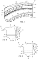
FIG. 3 illustrates a perspective view of the turbine blades assembled to a disc, and the cover plate shown in position; -
FIG. 4 illustrates an enlarged sectional view taken from arrow 4-4 ofFIG. 2 , showing a segmented cover plate assembly installed in the disc, with the cover plate and retainer clip locked in place; -
FIG. 5 illustrates a step showing the cover plate being inserted within the groove of the rotor blade body; -
FIG. 6 illustrates a step showing the cover plate fully positioned in place relative to the groove of the blade and disc; -
FIG. 7 illustrates an enlarged sectional view taken from arrow 7-7 ofFIG. 2 , showing the smash plate installed in the turbine assembly; and -
FIG. 8 is a side view of a segmented retainer clip or ring that is utilized in the novel assembly. - An improved method is disclosed to axially retain segmented cover plates in relation to a turbine disc using a segmented retainer ring. Segmented cover plates are provided which are retained at their radially outward edge by grooves in the underside of the blade platform. The cover plates are axially retained at their radially inward edge by retainer ring segments which are inserted below each cover plate segment in groove in the disc. Segmented cover plates known as smash plates are also used and they do not require retainer ring segments. This arrangement allows the segmented cover plates to be assembled with the bladed disc without cover plate loading slots in the disc or staggering the blades to create assembly clearance.
- The improved system allows the use of segmented cover plates in turbine configurations where it is not possible to stagger the blades to create assembly clearance. The improved system also avoids cover plate loading slots in the disc which can be high stress features. The improved system includes a method to axially retain segmented cover plates in relation to a turbine disc using a segmented retainer ring.
-
Figure 1 illustrates agas turbine engine 10, which includes afan 12, an intermediate pressure compressor and a high pressure compressor, 14 and 16, acombustor 18, a high pressure turbine, an intermediate pressure turbine, and a low pressure turbine, 20 and 21 and 22, respectively. Thehigh pressure compressor 16 is connected to afirst rotor shaft 24 while theintermediate pressure compressor 14 is connected to asecond rotor shaft 26 and the fan is connected to athird rotor shaft 42. The shafts extend axially and are parallel to a longitudinalcenter line axis 28. -
Ambient air 30 enters thefan 12 and is directed across afan rotor 32 in anannular duct 34, which in part is circumscribed byfan case 36. Thebypass airflow 38 provides engine thrust while theprimary gas stream 40 is directed to thecombustor 18 and thehigh pressure turbine 20. Thegas turbine engine 10 includes an improved turbine segmentedcover plate assembly 50 and method of installation for axially retaining turbine blades to a body of a turbine disc. -
FIG. 2 illustrates a front view of thelow pressure turbine 22 assembly employing the improved turbine segmentedcover plate assembly 50 along with the turbine blades and a turbine disc. It will be appreciated that thecover plate assembly 50 may be employed with the high pressure and intermediate pressure turbines, 20, 21. For demonstrative purposes only, a discussion of thecover plate assembly 50 will be presented in the context of thelow pressure turbine 22. - With reference to
FIGS. 2 and3 , theturbine 22 includes adisc 52 having adisc body 53, anannular groove 55 that circumscribes thebody 53, a segmented retainer ring orclip 56 slideably positioned within thegroove 55, a cover plate orlocking member 58,smash plates 60, andturbine blades 62.Exemplary smash plates 60 are located at the 12 o'clock, 4 o'clock and 8 o'clock positions. It will be appreciate that more orless smash plates 60 may be used with theturbine 22 assembly and they may be positioned at alternative locations. The segmented ring(s) 56 are approximately the same length as the segmented cover plate(s). It will be appreciated that eachcover plate 58 has a width encompassing about fourblade plat forms 66, however the width could be more or less. The segmentedcover plates 58 and segmentedring 54 are arcuate shaped in the side profile and have a similar geometric configuration and length. - The
disc body 53 of theturbine 22 includes a plurality of axially extendinggrooves 54 that are circumferentially spaced about the perimeter of thebody 52. Thegrooves 54 are configured to receive ablade root 64 of eachrotor blade 62. Theblade root 64 leads into ablade platform 66 which in turns is the base in which the aerodynamic rotor blades (not shown) are supported. Eachblade 62 is operable to slide axially relative to the correspondingaxial groove 54, and they are axially retained in place by the combination of theretainer clip 56 and thecover plate 58. -
FIG. 4 illustrates thecover plate assembly 50 retaining theblade 62 relative to thedisc 52. Thebody 53 of thedisc 52 includes the circumferentially spacedannular groove 55 that is positioned in a retainingarm 68 that extends from aface 70 of theassembly 50. The retainingarm 68 includes aradially extending portion 72 that extends opposite the direction of thecenterline 28 of themachine 10. Distally opposed from thegroove 55 is anotherannular groove 74 that extends circumferentially around theblade 62. Thegroove 74 is located in aninner shroud 76 that too extends circumferentially around theblade 62. Atab 78 radially extends towards thedisc 52 and aids to retain an upper portion of thecover plate 58 in place. - The
retainer clip 56 impinges upon thesurface 88 of thecover plate 58 such that once it is installed withingroove 55, thecover plate 58 and theclip 56 bias theblade 62 axially in thegroove 54 so that theblade 62 is firmly secured in place. Theretainer clip 56 has amain body 82, an upwardly extendingarm 84, and a notchedportion 86. While an exemplary L-shaped clip is depicted, it will be appreciated that other shaped configurations may be employed. Thelower end 88 of thecover plate 58 is positioned within thenotch 86 which firmly positions thelower end 88 of thecover plate 58. Thecover plate 58 and theclip 56 may be constructed of high temperature steel or other material as long as it withstands gas turbine rotor operating conditions. Thecover plate 58 is substantially flat and has acentral portion 90, thelower portion 88, and anupper portion 92 which includes an arcuate member for being received within thegroove 74. It will be appreciated that thedisc 52 and theblades 62 are constructed of materials that are known in the gas turbine industry. - The method of installing a
cover plate assembly 50 will now be described. With reference toFIG. 5 , theblade 62 has been positioned relative to thedisc wheel 52 so that theface 70 of each structure is substantially in alignment. This is accomplished by axially sliding theblade 62 within thegroove 54 of thedisc 52 to a point where thefaces 70 are flush. The next step includes theupper portion 92 of thecover plate 58 being located within thegroove 74. Thelower end 88 of thecover plate 58 may then be advanced towards theface 70 to a position shown inFIG. 6 . Thelower end 88 of thecover plate 58 clears theradially extending member 72 of the retainingarm 68. Thecover plate 58 rests against theface 70. -
FIG. 6 shows thecover plate 58 properly in a position ready for theretainer clip 56 to be installed. Theretainer clip 56 secures thecover plate 58 in position at the locations where asmash plate 60 is not employed. - For the next step, with reference back to
FIG. 4 , theretainer clip 56 is now slid in place withingroove 55 so as to sandwich thelower end 88 of thecover plate 58 against theface 70. This arrangement axially retains theblade 62 within thegroove 54 and maintains thedisc 52 andblade 62 relative to one another. The next step includes installing thesmash plate members 60 in place relative to theturbine body 53. -
FIG. 7 , which is a sectional view taken from arrow 7-7 ofFIG. 2 , depicts asmash plate 60 being positioned withinsections turbine body 52. SeeFIG. 2 . For illustrative purposes only a section cut is shown throughsection 98. However, similar sections are present atsections smash plate 60 is c-shaped in the end profile and is located withingrooves smash plate 60 has anaxially extending lip 100 that consumes a substantial portion of thegroove 55. Eachsmash plate 60 is a metallic member that is operable to be forced into position as shown inFIG. 7 . - During operation of the
machine 10, theclip 56 andcover plate 58 collectively aid to hold theblades 62 in place and reduce fluid leakage within thesystem 10. Likewise thesmash plates 60 retain theadjacent blades 62 anddisc 52 in position. - To remove a
blade 62 from theturbine assembly 22, the inverse of the aforementioned steps is employed. In particular, one or more of thesmash plates 60 are removed. This clears the path for the retainingclip 56 to be clocked or rotated towards an open space or void that has been created as a result of the smash plate(s) 60 being removed. It will be appreciated that one or more of thesmash plates 60 may be removed for this process depending on the circumstances as hand. - Now that a void has been created by the removal of a
smash plate 60,retainer clip 56 may be clocked towards the void which permits theclip 56 to be slid out of thegroove 55. This action clears the way for thecover plate 58 to be rotated out, for example as is shown inFIG. 5 , so as to remove theclip 56 from theturbine assembly 22. Once theplate 58 has been removed, theblade 62 likewise is free to be axially slid apart from thedisc 52. To re-install theblade 62 or install anew blade 62, the inverse of the aforementioned steps may be employed. - Even though the present disclosure has been described in detail with reference to specific embodiments, it will be appreciated that the various modifications and changes can be made to these embodiments without departing from the scope of the present disclosure as set forth in the claims. The specification and the drawings are to be regarded as an illustrative thought instead of merely restrictive thought.
Claims (11)
- A disc and cover plate assembly (50) for a gas turbine engine (10) comprising:a turbine disc (52) having a first groove (55) on an axial face of the turbine disc (52);a turbine blade (62) having a second groove (74) on an axial face (70) of the turbine blade (62);at least one smash plate (60) positioned within the first groove (55) of the turbine disc (52), wherein axial retention of the turbine blade (62) relative to the turbine disc (52) is aided by the smash plate (60); characterized byat least one segmented cover plate (58) having an upper portion (92) and a lower end (88), such that when the upper portion (92) is located within the second groove (74) the lower end (88) clears the first groove (55); andat least one retainer member (56) positioned within the first groove (55) of the turbine disc (52), the retainer member (56) having a contact surface (84, 86) comprising a notched portion (86) for retaining the segmented cover plate (58) in place relative to the turbine disc (52) and relative to the turbine blade (62).
- The disc and cover plate assembly (50) according to any of claim 1, wherein the turbine disc (52) includes a third groove (54), said third groove (54) extends axially and is operable to receive a portion (64) of the turbine blade (62).
- The disc and cover plate assembly (50) according to any of the preceding claims, wherein the first groove (55) extends circumferentially substantially around a perimeter of the disc (52).
- The disc and cover plate assembly (50) according to any one of the preceding claims, wherein the retainer member (56) is a segmented ring (56), the segmented ring (56) has a notched portion (86) that engages an end (88) of the segmented cover plate (58).
- The disc and cover plate assembly (50) according to any of the preceding claims, wherein the segmented cover plate (58) and the retainer member (56) consume substantially all of the space that exists within the first groove (55) of the turbine disc (52).
- The disc and cover plate assembly (50) according to any of the preceding claims, wherein the smash plate (60) is collapsible between a first position and a second position.
- The disc and cover plate assembly (50) according to any one of the preceding claims, wherein the turbine blade (62) includes a blade root portion (64), said blade root portion (64) is configured to mate with a second groove (54) disposed on the turbine disc (52).
- The disc and cover plate assembly (50) according to any one of the preceding claims, wherein the retaining member (56) is a segmented ring (56), the segmented ring (56) and cover plate (58) operate to secure the blade (62) and disc (52) relative to one another.
- The disc and cover plate assembly (50) according to any of the preceding claims, wherein a plurality of retaining members (56) are positioned at various locations about a circumference of the assembly (50).
- The disc and cover plate assembly (50) according to any of the preceding claims, wherein the retaining member (56) is arcuate shaped.
- A method of assembling a cover plate (58) to a gas turbine engine disc (52) comprising the steps of:a. providing a disc (52);b. providing at least one segmented cover plate (58);c. providing a blade (62);d. providing at least one segmented retainer ring (56);e. providing at least one smash plate (60);f. inserting one segmented cover plate (58) into place relative to the disc (52) and the blade (62) and into a first disc groove (55) on an axial face of the disc (52) and into a second disc groove (74) on an axial face (70) of the blade (62);g. inserting a segmented retainer ring (56) into the first disc groove (55) adjacent to the segmented cover plate (58);h. sliding the segmented retainer ring (56) into a position beneath the segmented cover plate (58);i. continuing inserting segmented cover plates (58) and segmented retainer rings (56) until a predetermined number of spaces for segmented cover plates (58) remain;j. arranging the cover plates (58) and segmented retainer rings (56) such that the predetermined number of open spaces that remain are located to a preferred location (94, 96, 98); andk. inserting a smash plate (60) in each open space.
Applications Claiming Priority (2)
| Application Number | Priority Date | Filing Date | Title |
|---|---|---|---|
| US201361773091P | 2013-03-05 | 2013-03-05 | |
| PCT/US2013/074499 WO2014137435A2 (en) | 2013-03-05 | 2013-12-11 | Turbine segmented cover plate retention method |
Publications (2)
| Publication Number | Publication Date |
|---|---|
| EP2964894A2 EP2964894A2 (en) | 2016-01-13 |
| EP2964894B1 true EP2964894B1 (en) | 2019-04-10 |
Family
ID=50983091
Family Applications (1)
| Application Number | Title | Priority Date | Filing Date |
|---|---|---|---|
| EP13866502.1A Not-in-force EP2964894B1 (en) | 2013-03-05 | 2013-12-11 | Turbine segmented cover plate retention method |
Country Status (3)
| Country | Link |
|---|---|
| US (1) | US9803485B2 (en) |
| EP (1) | EP2964894B1 (en) |
| WO (1) | WO2014137435A2 (en) |
Cited By (1)
| Publication number | Priority date | Publication date | Assignee | Title |
|---|---|---|---|---|
| US10876429B2 (en) | 2019-03-21 | 2020-12-29 | Pratt & Whitney Canada Corp. | Shroud segment assembly intersegment end gaps control |
Families Citing this family (9)
| Publication number | Priority date | Publication date | Assignee | Title |
|---|---|---|---|---|
| JP5358031B1 (en) * | 2013-03-22 | 2013-12-04 | 三菱重工業株式会社 | Turbine rotor, turbine, and seal plate removal method |
| WO2015112226A2 (en) * | 2013-12-19 | 2015-07-30 | United Technologies Corporation | Blade feature to support segmented coverplate |
| EP2975218A1 (en) * | 2014-07-17 | 2016-01-20 | Siemens Aktiengesellschaft | Wheel disc assembly |
| JP6613611B2 (en) * | 2015-05-15 | 2019-12-04 | 株式会社Ihi | Turbine blade mounting structure |
| DE102015116935A1 (en) * | 2015-10-06 | 2017-04-06 | Rolls-Royce Deutschland Ltd & Co Kg | Safety device for axially securing a blade and rotor device with such a securing device |
| DE102016107315A1 (en) * | 2016-04-20 | 2017-10-26 | Rolls-Royce Deutschland Ltd & Co Kg | Rotor with overhang on blades for a safety element |
| US10920598B2 (en) * | 2017-05-02 | 2021-02-16 | Rolls-Royce Corporation | Rotor assembly cover plate |
| KR102205571B1 (en) | 2019-06-05 | 2021-01-20 | 두산중공업 주식회사 | Fixing and sealing structure between turbine blade and turbine rotor disk |
| US11168615B1 (en) | 2020-08-25 | 2021-11-09 | Raytheon Technologies Corporation | Double ring axial sealing design |
Citations (2)
| Publication number | Priority date | Publication date | Assignee | Title |
|---|---|---|---|---|
| US3807898A (en) * | 1970-03-14 | 1974-04-30 | Secr Defence | Bladed rotor assemblies |
| US20080181767A1 (en) * | 2007-01-30 | 2008-07-31 | Siemens Power Generation, Inc. | Turbine seal plate locking system |
Family Cites Families (25)
| Publication number | Priority date | Publication date | Assignee | Title |
|---|---|---|---|---|
| US3656865A (en) | 1970-07-21 | 1972-04-18 | Gen Motors Corp | Rotor blade retainer |
| US3853425A (en) | 1973-09-07 | 1974-12-10 | Westinghouse Electric Corp | Turbine rotor blade cooling and sealing system |
| GB1479332A (en) | 1974-11-06 | 1977-07-13 | Rolls Royce | Means for retaining blades to a disc or like structure |
| GB1512882A (en) * | 1976-02-11 | 1978-06-01 | Rolls Royce | Bladed rotor assembly for a gas turbine engine |
| US4648799A (en) | 1981-09-22 | 1987-03-10 | Westinghouse Electric Corp. | Cooled combustion turbine blade with retrofit blade seal |
| US5256035A (en) | 1992-06-01 | 1993-10-26 | United Technologies Corporation | Rotor blade retention and sealing construction |
| FR2694046B1 (en) * | 1992-07-22 | 1994-09-23 | Snecma | Sealing and retention device for a rotor notched with pinouts receiving blade roots. |
| US5622475A (en) | 1994-08-30 | 1997-04-22 | General Electric Company | Double rabbet rotor blade retention assembly |
| US5525429A (en) * | 1995-03-06 | 1996-06-11 | General Electric Company | Laser shock peening surface enhancement for gas turbine engine high strength rotor alloy repair |
| GB2332024B (en) | 1997-12-03 | 2000-12-13 | Rolls Royce Plc | Rotary assembly |
| FR2812906B1 (en) | 2000-08-10 | 2002-09-20 | Snecma Moteurs | AXIAL RETAINER RING OF A FLANGE ON A DISC |
| US6884028B2 (en) * | 2002-09-30 | 2005-04-26 | General Electric Company | Turbomachinery blade retention system |
| FR2857691B1 (en) * | 2003-07-17 | 2006-02-03 | Snecma Moteurs | RETENTION OF ROTOR FLASK |
| JP3864157B2 (en) | 2003-12-05 | 2006-12-27 | 本田技研工業株式会社 | Axial turbine wheel |
| US7238008B2 (en) | 2004-05-28 | 2007-07-03 | General Electric Company | Turbine blade retainer seal |
| GB0503676D0 (en) | 2005-02-23 | 2005-03-30 | Rolls Royce Plc | A lock plate arrangement |
| DE102005035901A1 (en) * | 2005-07-30 | 2007-02-01 | Mtu Aero Engines Gmbh | Rotor blades` position securing unit for gas turbine, has plate-like base body having recess formed between its two end sections, where recess defines middle section of body and sections have contact surfaces running parallel to each other |
| US8105041B2 (en) | 2005-09-07 | 2012-01-31 | Siemens Aktiengesellschaft | Arrangement for axially securing rotating blades in a rotor, sealing element for such an arrangement, and use of such an arrangement |
| GB0524929D0 (en) | 2005-12-06 | 2006-01-18 | Rolls Royce Plc | Retention arrangement |
| EP1916389A1 (en) | 2006-10-26 | 2008-04-30 | Siemens Aktiengesellschaft | Turbine blade assembly |
| ATE441776T1 (en) | 2007-01-09 | 2009-09-15 | Siemens Ag | AXIAL ROTOR SECTION FOR A ROTOR OF A TURBINE |
| US8128371B2 (en) | 2007-02-15 | 2012-03-06 | General Electric Company | Method and apparatus to facilitate increasing turbine rotor efficiency |
| FR2918106B1 (en) | 2007-06-27 | 2011-05-06 | Snecma | AXIS RETAINING DEVICE OF AUBES MOUNTED ON A TURBOMACHINE ROTOR DISC. |
| US8206119B2 (en) | 2009-02-05 | 2012-06-26 | General Electric Company | Turbine coverplate systems |
| EP2239419A1 (en) | 2009-03-31 | 2010-10-13 | Siemens Aktiengesellschaft | Axial turbo engine rotor with sealing disc |
-
2013
- 2013-12-11 US US14/103,106 patent/US9803485B2/en active Active
- 2013-12-11 EP EP13866502.1A patent/EP2964894B1/en not_active Not-in-force
- 2013-12-11 WO PCT/US2013/074499 patent/WO2014137435A2/en active Application Filing
Patent Citations (2)
| Publication number | Priority date | Publication date | Assignee | Title |
|---|---|---|---|---|
| US3807898A (en) * | 1970-03-14 | 1974-04-30 | Secr Defence | Bladed rotor assemblies |
| US20080181767A1 (en) * | 2007-01-30 | 2008-07-31 | Siemens Power Generation, Inc. | Turbine seal plate locking system |
Cited By (1)
| Publication number | Priority date | Publication date | Assignee | Title |
|---|---|---|---|---|
| US10876429B2 (en) | 2019-03-21 | 2020-12-29 | Pratt & Whitney Canada Corp. | Shroud segment assembly intersegment end gaps control |
Also Published As
| Publication number | Publication date |
|---|---|
| EP2964894A2 (en) | 2016-01-13 |
| US9803485B2 (en) | 2017-10-31 |
| WO2014137435A3 (en) | 2014-11-13 |
| US20140356177A1 (en) | 2014-12-04 |
| WO2014137435A2 (en) | 2014-09-12 |
Similar Documents
| Publication | Publication Date | Title |
|---|---|---|
| EP2964894B1 (en) | Turbine segmented cover plate retention method | |
| EP1965031B1 (en) | Blade outer air seal assembly | |
| US10436070B2 (en) | Blade outer air seal having angled retention hook | |
| US6884028B2 (en) | Turbomachinery blade retention system | |
| US10184356B2 (en) | Blade outer air seal support structure | |
| CN105781625B (en) | Fixture and method for mounting turbine buckets | |
| EP2615256B1 (en) | Spring "t" seal of a gas turbine | |
| US10738626B2 (en) | Connection assemblies between turbine rotor blades and rotor wheels | |
| US10184345B2 (en) | Cover plate assembly for a gas turbine engine | |
| US10655481B2 (en) | Cover plate for rotor assembly of a gas turbine engine | |
| EP3048263B1 (en) | Gas turbine active clearance control system | |
| EP3112615B1 (en) | Compressor section with a particular arrangement to hold a vane | |
| US11313239B2 (en) | Turbmachine fan disc | |
| US9540955B2 (en) | Stator assembly | |
| EP2957721B1 (en) | Turbine section of a gas turbine engine, with disk cooling and an interstage seal having a particular geometry | |
| US20210010380A1 (en) | Turbine engine with a seal | |
| EP2855896B1 (en) | Stator vane mistake proofing |
Legal Events
| Date | Code | Title | Description |
|---|---|---|---|
| PUAI | Public reference made under article 153(3) epc to a published international application that has entered the european phase |
Free format text: ORIGINAL CODE: 0009012 |
|
| 17P | Request for examination filed |
Effective date: 20151002 |
|
| AK | Designated contracting states |
Kind code of ref document: A2 Designated state(s): AL AT BE BG CH CY CZ DE DK EE ES FI FR GB GR HR HU IE IS IT LI LT LU LV MC MK MT NL NO PL PT RO RS SE SI SK SM TR |
|
| AX | Request for extension of the european patent |
Extension state: BA ME |
|
| DAX | Request for extension of the european patent (deleted) | ||
| STAA | Information on the status of an ep patent application or granted ep patent |
Free format text: STATUS: EXAMINATION IS IN PROGRESS |
|
| 17Q | First examination report despatched |
Effective date: 20170202 |
|
| GRAP | Despatch of communication of intention to grant a patent |
Free format text: ORIGINAL CODE: EPIDOSNIGR1 |
|
| STAA | Information on the status of an ep patent application or granted ep patent |
Free format text: STATUS: GRANT OF PATENT IS INTENDED |
|
| INTG | Intention to grant announced |
Effective date: 20181129 |
|
| GRAS | Grant fee paid |
Free format text: ORIGINAL CODE: EPIDOSNIGR3 |
|
| GRAA | (expected) grant |
Free format text: ORIGINAL CODE: 0009210 |
|
| STAA | Information on the status of an ep patent application or granted ep patent |
Free format text: STATUS: THE PATENT HAS BEEN GRANTED |
|
| AK | Designated contracting states |
Kind code of ref document: B1 Designated state(s): AL AT BE BG CH CY CZ DE DK EE ES FI FR GB GR HR HU IE IS IT LI LT LU LV MC MK MT NL NO PL PT RO RS SE SI SK SM TR |
|
| REG | Reference to a national code |
Ref country code: GB Ref legal event code: FG4D |
|
| REG | Reference to a national code |
Ref country code: CH Ref legal event code: EP Ref country code: AT Ref legal event code: REF Ref document number: 1118911 Country of ref document: AT Kind code of ref document: T Effective date: 20190415 |
|
| REG | Reference to a national code |
Ref country code: IE Ref legal event code: FG4D |
|
| REG | Reference to a national code |
Ref country code: DE Ref legal event code: R096 Ref document number: 602013053865 Country of ref document: DE |
|
| REG | Reference to a national code |
Ref country code: NL Ref legal event code: MP Effective date: 20190410 |
|
| REG | Reference to a national code |
Ref country code: LT Ref legal event code: MG4D |
|
| REG | Reference to a national code |
Ref country code: AT Ref legal event code: MK05 Ref document number: 1118911 Country of ref document: AT Kind code of ref document: T Effective date: 20190410 |
|
| PG25 | Lapsed in a contracting state [announced via postgrant information from national office to epo] |
Ref country code: NL Free format text: LAPSE BECAUSE OF FAILURE TO SUBMIT A TRANSLATION OF THE DESCRIPTION OR TO PAY THE FEE WITHIN THE PRESCRIBED TIME-LIMIT Effective date: 20190410 |
|
| PG25 | Lapsed in a contracting state [announced via postgrant information from national office to epo] |
Ref country code: FI Free format text: LAPSE BECAUSE OF FAILURE TO SUBMIT A TRANSLATION OF THE DESCRIPTION OR TO PAY THE FEE WITHIN THE PRESCRIBED TIME-LIMIT Effective date: 20190410 Ref country code: NO Free format text: LAPSE BECAUSE OF FAILURE TO SUBMIT A TRANSLATION OF THE DESCRIPTION OR TO PAY THE FEE WITHIN THE PRESCRIBED TIME-LIMIT Effective date: 20190710 Ref country code: LT Free format text: LAPSE BECAUSE OF FAILURE TO SUBMIT A TRANSLATION OF THE DESCRIPTION OR TO PAY THE FEE WITHIN THE PRESCRIBED TIME-LIMIT Effective date: 20190410 Ref country code: ES Free format text: LAPSE BECAUSE OF FAILURE TO SUBMIT A TRANSLATION OF THE DESCRIPTION OR TO PAY THE FEE WITHIN THE PRESCRIBED TIME-LIMIT Effective date: 20190410 Ref country code: AL Free format text: LAPSE BECAUSE OF FAILURE TO SUBMIT A TRANSLATION OF THE DESCRIPTION OR TO PAY THE FEE WITHIN THE PRESCRIBED TIME-LIMIT Effective date: 20190410 Ref country code: HR Free format text: LAPSE BECAUSE OF FAILURE TO SUBMIT A TRANSLATION OF THE DESCRIPTION OR TO PAY THE FEE WITHIN THE PRESCRIBED TIME-LIMIT Effective date: 20190410 Ref country code: SE Free format text: LAPSE BECAUSE OF FAILURE TO SUBMIT A TRANSLATION OF THE DESCRIPTION OR TO PAY THE FEE WITHIN THE PRESCRIBED TIME-LIMIT Effective date: 20190410 Ref country code: PT Free format text: LAPSE BECAUSE OF FAILURE TO SUBMIT A TRANSLATION OF THE DESCRIPTION OR TO PAY THE FEE WITHIN THE PRESCRIBED TIME-LIMIT Effective date: 20190910 |
|
| PG25 | Lapsed in a contracting state [announced via postgrant information from national office to epo] |
Ref country code: PL Free format text: LAPSE BECAUSE OF FAILURE TO SUBMIT A TRANSLATION OF THE DESCRIPTION OR TO PAY THE FEE WITHIN THE PRESCRIBED TIME-LIMIT Effective date: 20190410 Ref country code: LV Free format text: LAPSE BECAUSE OF FAILURE TO SUBMIT A TRANSLATION OF THE DESCRIPTION OR TO PAY THE FEE WITHIN THE PRESCRIBED TIME-LIMIT Effective date: 20190410 Ref country code: GR Free format text: LAPSE BECAUSE OF FAILURE TO SUBMIT A TRANSLATION OF THE DESCRIPTION OR TO PAY THE FEE WITHIN THE PRESCRIBED TIME-LIMIT Effective date: 20190711 Ref country code: BG Free format text: LAPSE BECAUSE OF FAILURE TO SUBMIT A TRANSLATION OF THE DESCRIPTION OR TO PAY THE FEE WITHIN THE PRESCRIBED TIME-LIMIT Effective date: 20190710 Ref country code: RS Free format text: LAPSE BECAUSE OF FAILURE TO SUBMIT A TRANSLATION OF THE DESCRIPTION OR TO PAY THE FEE WITHIN THE PRESCRIBED TIME-LIMIT Effective date: 20190410 |
|
| PG25 | Lapsed in a contracting state [announced via postgrant information from national office to epo] |
Ref country code: AT Free format text: LAPSE BECAUSE OF FAILURE TO SUBMIT A TRANSLATION OF THE DESCRIPTION OR TO PAY THE FEE WITHIN THE PRESCRIBED TIME-LIMIT Effective date: 20190410 Ref country code: IS Free format text: LAPSE BECAUSE OF FAILURE TO SUBMIT A TRANSLATION OF THE DESCRIPTION OR TO PAY THE FEE WITHIN THE PRESCRIBED TIME-LIMIT Effective date: 20190810 |
|
| REG | Reference to a national code |
Ref country code: DE Ref legal event code: R097 Ref document number: 602013053865 Country of ref document: DE |
|
| PG25 | Lapsed in a contracting state [announced via postgrant information from national office to epo] |
Ref country code: SK Free format text: LAPSE BECAUSE OF FAILURE TO SUBMIT A TRANSLATION OF THE DESCRIPTION OR TO PAY THE FEE WITHIN THE PRESCRIBED TIME-LIMIT Effective date: 20190410 Ref country code: EE Free format text: LAPSE BECAUSE OF FAILURE TO SUBMIT A TRANSLATION OF THE DESCRIPTION OR TO PAY THE FEE WITHIN THE PRESCRIBED TIME-LIMIT Effective date: 20190410 Ref country code: RO Free format text: LAPSE BECAUSE OF FAILURE TO SUBMIT A TRANSLATION OF THE DESCRIPTION OR TO PAY THE FEE WITHIN THE PRESCRIBED TIME-LIMIT Effective date: 20190410 Ref country code: CZ Free format text: LAPSE BECAUSE OF FAILURE TO SUBMIT A TRANSLATION OF THE DESCRIPTION OR TO PAY THE FEE WITHIN THE PRESCRIBED TIME-LIMIT Effective date: 20190410 Ref country code: DK Free format text: LAPSE BECAUSE OF FAILURE TO SUBMIT A TRANSLATION OF THE DESCRIPTION OR TO PAY THE FEE WITHIN THE PRESCRIBED TIME-LIMIT Effective date: 20190410 |
|
| PLBE | No opposition filed within time limit |
Free format text: ORIGINAL CODE: 0009261 |
|
| STAA | Information on the status of an ep patent application or granted ep patent |
Free format text: STATUS: NO OPPOSITION FILED WITHIN TIME LIMIT |
|
| PG25 | Lapsed in a contracting state [announced via postgrant information from national office to epo] |
Ref country code: IT Free format text: LAPSE BECAUSE OF FAILURE TO SUBMIT A TRANSLATION OF THE DESCRIPTION OR TO PAY THE FEE WITHIN THE PRESCRIBED TIME-LIMIT Effective date: 20190410 Ref country code: SM Free format text: LAPSE BECAUSE OF FAILURE TO SUBMIT A TRANSLATION OF THE DESCRIPTION OR TO PAY THE FEE WITHIN THE PRESCRIBED TIME-LIMIT Effective date: 20190410 |
|
| PGFP | Annual fee paid to national office [announced via postgrant information from national office to epo] |
Ref country code: FR Payment date: 20191226 Year of fee payment: 7 |
|
| 26N | No opposition filed |
Effective date: 20200113 |
|
| PG25 | Lapsed in a contracting state [announced via postgrant information from national office to epo] |
Ref country code: TR Free format text: LAPSE BECAUSE OF FAILURE TO SUBMIT A TRANSLATION OF THE DESCRIPTION OR TO PAY THE FEE WITHIN THE PRESCRIBED TIME-LIMIT Effective date: 20190410 |
|
| PGFP | Annual fee paid to national office [announced via postgrant information from national office to epo] |
Ref country code: DE Payment date: 20191231 Year of fee payment: 7 |
|
| PG25 | Lapsed in a contracting state [announced via postgrant information from national office to epo] |
Ref country code: SI Free format text: LAPSE BECAUSE OF FAILURE TO SUBMIT A TRANSLATION OF THE DESCRIPTION OR TO PAY THE FEE WITHIN THE PRESCRIBED TIME-LIMIT Effective date: 20190410 |
|
| REG | Reference to a national code |
Ref country code: CH Ref legal event code: PL |
|
| REG | Reference to a national code |
Ref country code: BE Ref legal event code: MM Effective date: 20191231 |
|
| PG25 | Lapsed in a contracting state [announced via postgrant information from national office to epo] |
Ref country code: MC Free format text: LAPSE BECAUSE OF FAILURE TO SUBMIT A TRANSLATION OF THE DESCRIPTION OR TO PAY THE FEE WITHIN THE PRESCRIBED TIME-LIMIT Effective date: 20190410 |
|
| GBPC | Gb: european patent ceased through non-payment of renewal fee |
Effective date: 20191211 |
|
| PG25 | Lapsed in a contracting state [announced via postgrant information from national office to epo] |
Ref country code: LU Free format text: LAPSE BECAUSE OF NON-PAYMENT OF DUE FEES Effective date: 20191211 Ref country code: IE Free format text: LAPSE BECAUSE OF NON-PAYMENT OF DUE FEES Effective date: 20191211 Ref country code: GB Free format text: LAPSE BECAUSE OF NON-PAYMENT OF DUE FEES Effective date: 20191211 |
|
| PG25 | Lapsed in a contracting state [announced via postgrant information from national office to epo] |
Ref country code: BE Free format text: LAPSE BECAUSE OF NON-PAYMENT OF DUE FEES Effective date: 20191231 Ref country code: CH Free format text: LAPSE BECAUSE OF NON-PAYMENT OF DUE FEES Effective date: 20191231 Ref country code: LI Free format text: LAPSE BECAUSE OF NON-PAYMENT OF DUE FEES Effective date: 20191231 |
|
| PG25 | Lapsed in a contracting state [announced via postgrant information from national office to epo] |
Ref country code: CY Free format text: LAPSE BECAUSE OF FAILURE TO SUBMIT A TRANSLATION OF THE DESCRIPTION OR TO PAY THE FEE WITHIN THE PRESCRIBED TIME-LIMIT Effective date: 20190410 |
|
| REG | Reference to a national code |
Ref country code: DE Ref legal event code: R119 Ref document number: 602013053865 Country of ref document: DE |
|
| PG25 | Lapsed in a contracting state [announced via postgrant information from national office to epo] |
Ref country code: HU Free format text: LAPSE BECAUSE OF FAILURE TO SUBMIT A TRANSLATION OF THE DESCRIPTION OR TO PAY THE FEE WITHIN THE PRESCRIBED TIME-LIMIT; INVALID AB INITIO Effective date: 20131211 Ref country code: MT Free format text: LAPSE BECAUSE OF FAILURE TO SUBMIT A TRANSLATION OF THE DESCRIPTION OR TO PAY THE FEE WITHIN THE PRESCRIBED TIME-LIMIT Effective date: 20190410 |
|
| PG25 | Lapsed in a contracting state [announced via postgrant information from national office to epo] |
Ref country code: FR Free format text: LAPSE BECAUSE OF NON-PAYMENT OF DUE FEES Effective date: 20201231 |
|
| PG25 | Lapsed in a contracting state [announced via postgrant information from national office to epo] |
Ref country code: DE Free format text: LAPSE BECAUSE OF NON-PAYMENT OF DUE FEES Effective date: 20210701 |
|
| PG25 | Lapsed in a contracting state [announced via postgrant information from national office to epo] |
Ref country code: MK Free format text: LAPSE BECAUSE OF FAILURE TO SUBMIT A TRANSLATION OF THE DESCRIPTION OR TO PAY THE FEE WITHIN THE PRESCRIBED TIME-LIMIT Effective date: 20190410 |