EP2562336A1 - Vehicle door lock device - Google Patents
Vehicle door lock device Download PDFInfo
- Publication number
- EP2562336A1 EP2562336A1 EP11771814A EP11771814A EP2562336A1 EP 2562336 A1 EP2562336 A1 EP 2562336A1 EP 11771814 A EP11771814 A EP 11771814A EP 11771814 A EP11771814 A EP 11771814A EP 2562336 A1 EP2562336 A1 EP 2562336A1
- Authority
- EP
- European Patent Office
- Prior art keywords
- housing
- communication path
- welded portion
- lock device
- door lock
- Prior art date
- Legal status (The legal status is an assumption and is not a legal conclusion. Google has not performed a legal analysis and makes no representation as to the accuracy of the status listed.)
- Granted
Links
Images


Classifications
-
- E—FIXED CONSTRUCTIONS
- E05—LOCKS; KEYS; WINDOW OR DOOR FITTINGS; SAFES
- E05B—LOCKS; ACCESSORIES THEREFOR; HANDCUFFS
- E05B85/00—Details of vehicle locks not provided for in groups E05B77/00 - E05B83/00
- E05B85/02—Lock casings
-
- E—FIXED CONSTRUCTIONS
- E05—LOCKS; KEYS; WINDOW OR DOOR FITTINGS; SAFES
- E05B—LOCKS; ACCESSORIES THEREFOR; HANDCUFFS
- E05B77/00—Vehicle locks characterised by special functions or purposes
- E05B77/34—Protection against weather or dirt, e.g. against water ingress
-
- E—FIXED CONSTRUCTIONS
- E05—LOCKS; KEYS; WINDOW OR DOOR FITTINGS; SAFES
- E05B—LOCKS; ACCESSORIES THEREFOR; HANDCUFFS
- E05B81/00—Power-actuated vehicle locks
- E05B81/02—Power-actuated vehicle locks characterised by the type of actuators used
- E05B81/04—Electrical
- E05B81/06—Electrical using rotary motors
-
- E—FIXED CONSTRUCTIONS
- E05—LOCKS; KEYS; WINDOW OR DOOR FITTINGS; SAFES
- E05B—LOCKS; ACCESSORIES THEREFOR; HANDCUFFS
- E05B81/00—Power-actuated vehicle locks
- E05B81/12—Power-actuated vehicle locks characterised by the function or purpose of the powered actuators
- E05B81/16—Power-actuated vehicle locks characterised by the function or purpose of the powered actuators operating on locking elements for locking or unlocking action
-
- Y—GENERAL TAGGING OF NEW TECHNOLOGICAL DEVELOPMENTS; GENERAL TAGGING OF CROSS-SECTIONAL TECHNOLOGIES SPANNING OVER SEVERAL SECTIONS OF THE IPC; TECHNICAL SUBJECTS COVERED BY FORMER USPC CROSS-REFERENCE ART COLLECTIONS [XRACs] AND DIGESTS
- Y10—TECHNICAL SUBJECTS COVERED BY FORMER USPC
- Y10T—TECHNICAL SUBJECTS COVERED BY FORMER US CLASSIFICATION
- Y10T292/00—Closure fasteners
- Y10T292/48—Seals
Definitions
- the present invention relates to a vehicle door lock device.
- a vehicle door lock device including: a latch mechanism, which is capable of keeping a door of a vehicle closed with respect to a body, and is assembled to the door together with a housing; a lever mechanism, which is assembled to the housing, and is driven through operation of a door handle provided to the door; a link mechanism, which is interposed in the housing between the latch mechanism and the lever mechanism, and is capable of being switched between an unlock state in which transmission of an operating force from the lever mechanism to the latch mechanism is enabled, and a lock state in which the transmission of the operating force is disabled; and an electric actuator (electrical part), which is assembled into the housing, and switches the link mechanism between the unlock state and the lock state.
- This vehicle door lock device is disclosed in, for example, Patent Document 1 below.
- Patent Document 1 JP 2006-233506 A
- waterproofing measures for the above-mentioned electric actuator (electrical part) are taken for the housing.
- the waterproofing measures described in the above-mentioned Patent Document 1 are taken in such a manner that a waterproof cover is disposed over the housing, and a water passage hole is formed in an upper portion of the housing, for preventing water from entering an accommodating space of the housing in which the electric actuator (electrical part) is accommodated.
- the vehicle door lock device described in the above-mentioned Patent Document 1 requires the waterproof cover, and hence the number of parts is increased. Further, the water passage hole formed in the upper portion of the housing can be expected to exert a desired function and provide desired waterproofing effects, but it is not assured that all of water, which falls to the upper portion of the housing and adheres thereto, flows into the water passage hole. Therefore, there is a fear in that water enters the accommodating space of the housing in which the electric actuator (electrical part) is accommodated.
- the present invention has been made to solve the above-mentioned problem, and therefore provides a vehicle door lock device, including: a latch mechanism, which is capable of keeping a door of a vehicle closed with respect to a body, and is adapted to be assembled to the door together with a housing; a lever mechanism, which is adapted to be assembled to the housing, and to be driven through operation of a door handle provided to the door; a link mechanism, which is interposed in the housing between the latch mechanism and the lever mechanism, and is capable of being switched between an unlock state in which transmission of an operating force from the lever mechanism to the latch mechanism is enabled, and a lock state in which the transmission of the operating force is disabled; and an electric actuator, which is assembled into the housing, and switches the link mechanism between the unlock state and the lock state; in which the housing includes a housing body and a housing cover joined to each other, and is arranged so that a joining surface between the housing body and the housing cover extends along an up-and-down direction, in which a sealing portion is formed along a joining portion
- the communication path may include: a communication groove formed in one of the housing body and the housing cover; and an end wall formed in another one of the housing body and the housing cover so as to close the communication groove.
- the inner welded portion and the outer welded portion may be formed by laser welding.
- the housing body may be made of a laser-beam-nontransmissive resin material
- the housing cover may be made of a laser-beam-transmissive resin material. Therefore, the inner welded portion and the outer welded portion may be subjected to the laser welding through irradiation of a laser beam from the housing cover side.
- the communication path may include one open end and another closed end, and the inner welded portion and the outer welded portion may be connected to each other at the another closed end. Further, the communication path may include both ends that are open downward.
- the sealing portion formed along the joining portion between the housing body and the housing cover is configured as described above, and hence the above-mentioned sealing portion prevents water, which falls from above to an upper portion of the housing and adheres thereto, from entering the inner space of the housing accommodating the link mechanism and the electric actuator. Therefore, according to the present invention, without use of a waterproof cover, the link mechanism and the electric actuator can be protected from the water with a simple and inexpensive configuration.
- the inner welded portion and the outer welded portion are formed continuously along the communication path, and hence the communication path except both ends thereof is sealed by the inner welded portion and the outer welded portion. Accordingly, pressurized gas (for example, compressed air) is charged into the communication path, and the gas pressure is examined. In this way, it is possible to easily determine whether or not the above-mentioned sealing portion maintains satisfactory sealing properties (airtightness and fluid-tightness).
- pressurized gas for example, compressed air
- the communication path includes the communication groove formed in one of the housing body and the housing cover, and the end wall formed in another one of the housing body and the housing cover so as to close the communication groove
- the communication path can be formed simply at low cost.
- the inner welded portion and the outer welded portion are formed by laser welding, in comparison to a case where the inner welded portion and the outer welded portion are formed by vibration welding, it is possible to suppress influence on components accommodated in the housing.
- the communication path includes one open end and another closed end, and the inner welded portion and the outer welded portion are connected to each other at the closed end, it is possible to charge pressurized gas (for example, compressed air) into the communication path from the open end portion of the communication path, and through connecting a connection tool capable of examining the gas pressure to the open end portion of the communication path, it is possible to easily determine whether or not the above-mentioned sealing portion maintains satisfactory sealing properties (airtightness and fluid-tightness).
- pressurized gas for example, compressed air
- the communication path includes both ends that are open downward
- the water is trapped in the communication path and is prevented from entering the upper part of the inner space of the housing.
- the water trapped in the communication path drips down from the end portion of the communication path, and hence does not enter the upper part of the inner space of the housing. Therefore, water falling from above can be appropriately prevented from entering the upper part of the inner space of the housing.
- FIGS. 1 to 5 illustrate a vehicle door lock device 100 according to the present invention.
- the vehicle door lock device 100 is installed in a door 201 mounted on a front right side of a vehicle.
- the vehicle door lock device 100 includes a latch mechanism 10, a lever mechanism 20, a link mechanism 30, and an electric actuator 40, which are assembled to a housing 50.
- the latch mechanism 10 keeps the door 201 of the vehicle closed with respect to a body (vehicle body (not shown)) (keeps a state in which the door 201 is closed), and includes a latch 11 which is engageable with and disengageable from a striker (not shown) fixed to the body.
- the latch mechanism 10 is assembled to the door 201 under a state in which the latch mechanism 10 is assembled to the housing 50.
- the lever mechanism 20 includes an inside open lever 21 which is driven in accordance with operation of an inside door handle (not shown) provided on an inner side of the door 201, and an outside open lever 22 which is driven in accordance with operation of an outside door handle (not shown) provided on an outer side of the door 201.
- the inside open lever 21 is assembled to the housing 50, and is linked with the inside door handle through the intermediation of an operation cable 61 illustrated in FIG. 1 (operating force transmitting member such as a link may be used instead).
- an operating force transmitting member such as a link may be used instead.
- the outside open lever 22 is assembled to the housing 50, and is linked with the outside door handle through the intermediation of an operating force transmitting member (not shown) such as a link.
- an operating force transmitting member not shown
- the link mechanism 30 is interposed in the housing 50 between the latch mechanism 10 and the lever mechanism 20, and includes an open link 31 which can be switched between an unlock state in which transmission of an operating force from the lever mechanism 20 to the latch mechanism 10 is enabled, and a lock state in which the transmission of the operating force is disabled.
- the open link 31 is interposed between the inside open lever 21 provided to the lever mechanism 20 and a lift lever (not shown) provided to the latch mechanism 10, and between the outside open lever 22 provided to the lever mechanism 20 and the lift lever.
- the open link 31 can be switched between an unlock position at which an action of each open lever 21, 22 in a door opening direction is transmitted to the lift lever (the transmission of the operating force is enabled), and a lock position at which the action of each open lever 21, 22 is not transmitted to the lift lever (the transmission of the operating force is disabled), the action of each open lever 21, 22 being accompanied when each door handle is operated to open the door.
- the electric actuator 40 is assembled into the housing 50, and can switch the link mechanism 30 between the unlock state and the lock state.
- the electric actuator 40 includes an electric motor 41, a worm 42, and a worm wheel 43, and further includes an active lever 44 which is driven by those components.
- the active lever 44 is coupled through the intermediation of an operation cable 62 illustrated in FIG. 1 to a lock knob (not shown) provided to the door 201 on an inner side of the vehicle, and can be driven also through manual operation of the lock knob (not shown).
- the active lever 44 is coupled also to a key cylinder (not shown) provided on the outer side of the door 201, and can be driven also through manual operation of the key cylinder (not shown).
- the housing 50 includes a housing body 51 and a housing cover 52 joined to each other, and is arranged so that a joining surface between the housing body 51 and the housing cover 52 extends along an up-and-down direction.
- a sealing portion S is formed so as to surround an upper part of an inner space R of the housing accommodating the link mechanism 30 and the electric actuator 40.
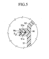
- a communication path P (see broken lines of FIG. 1 ) which is formed along the joining portion, and includes one open end Pa and another closed end Pb. Further, as illustrated exaggeratedly in FIG. 5 , on an inner side of the housing and an outer side of the housing with respect to the communication path P, an inner welded portion Wi and an outer welded portion Wo are formed continuously along the communication path P, respectively.
- the communication path P includes a communication groove 51 a formed in the housing body 51 to have a rectangular cross-section, and an end wall 52a formed in the housing cover 52 so as to close the communication groove 51a.
- the communication path (P) may include a communication groove formed in the housing cover (52), and an end wall formed in the housing body (51) so as to close the communication groove.
- the inner welded portion Wi and the outer welded portion Wo are formed by laser welding. Further, the inner welded portion Wi and the outer welded portion Wo are connected to each other at the closed end Pb of the communication path P, and seal a periphery of the communication path P except the open end Pa of the communication path P airtightly and fluid-tightly. Further, in this embodiment, the housing body 51 is made of a laser-beam-nontransmissive resin material, whereas the housing cover 52 is made of a laser-beam-transmissive resin material. A laser beam having a light intensity necessary for desired laser welding is irradiated from the housing cover 52 side.
- the sealing portion S formed along the joining portion between the housing body 51 and the housing cover 52 is configured as described above, and hence the above-mentioned sealing portion S prevents water, which falls from above to an upper portion of the housing 50 and adheres thereto, from entering the inner space R of the housing accommodating the link mechanism 30 and the electric actuator 40. Therefore, in this embodiment, without use of a waterproof cover, the link mechanism 30 and the electric actuator 40 can be protected from the water with a simple and inexpensive configuration.
- the inner welded portion Wi and the outer welded portion Wo are formed continuously along the communication path P, and are connected to each other at the closed end Pb of the communication path P.
- the communication path P except the open end Pa is sealed by the inner welded portion Wi and the outer welded portion Wo airtightly and fluid-tightly.
- pressurized gas for example, compressed air
- a connection tool capable of examining the gas pressure to the open end portion of the communication path P
- the communication path P includes the communication groove 51a formed in the housing body 51, and the end wall 52a formed in the housing cover 52 so as to close the communication groove 51 a, and hence the communication path S can be formed simply at low cost.
- the inner welded portion Wi and the outer welded portion Wo are formed by laser welding, and hence in comparison to a case where the inner welded portion Wi and the outer welded portion Wo are formed by vibration welding, it is possible to suppress influence on components accommodated in the housing 50.
- the present invention is carried out in such a manner that the communication path P is shaped to include the one open end Pa and the another closed end Pb, but may be carried out in such a manner that the communication path (P) is shaped to include both ends that are open downward.
- the water is trapped in the communication path (P) and is prevented from entering the upper part of the inner space (R) of the housing.
- the water trapped in the communication path (P) drips down from the end portion of the communication path (P), and hence does not enter the upper part of the inner space (R) of the housing. Therefore, water falling from above can be appropriately prevented from entering the upper part of the inner space (R) of the housing.
Landscapes
- Lock And Its Accessories (AREA)
Abstract
Description
- The present invention relates to a vehicle door lock device.
- As one of vehicle door lock devices, there is known a vehicle door lock device including: a latch mechanism, which is capable of keeping a door of a vehicle closed with respect to a body, and is assembled to the door together with a housing; a lever mechanism, which is assembled to the housing, and is driven through operation of a door handle provided to the door; a link mechanism, which is interposed in the housing between the latch mechanism and the lever mechanism, and is capable of being switched between an unlock state in which transmission of an operating force from the lever mechanism to the latch mechanism is enabled, and a lock state in which the transmission of the operating force is disabled; and an electric actuator (electrical part), which is assembled into the housing, and switches the link mechanism between the unlock state and the lock state. This vehicle door lock device is disclosed in, for example, Patent Document 1 below.
- Patent Document 1:
JP 2006-233506 A - In the vehicle door lock device described in the above-mentioned Patent Document 1, waterproofing measures for the above-mentioned electric actuator (electrical part) are taken for the housing. The waterproofing measures described in the above-mentioned Patent Document 1 are taken in such a manner that a waterproof cover is disposed over the housing, and a water passage hole is formed in an upper portion of the housing, for preventing water from entering an accommodating space of the housing in which the electric actuator (electrical part) is accommodated.
- By the way, the vehicle door lock device described in the above-mentioned Patent Document 1 requires the waterproof cover, and hence the number of parts is increased. Further, the water passage hole formed in the upper portion of the housing can be expected to exert a desired function and provide desired waterproofing effects, but it is not assured that all of water, which falls to the upper portion of the housing and adheres thereto, flows into the water passage hole. Therefore, there is a fear in that water enters the accommodating space of the housing in which the electric actuator (electrical part) is accommodated.
- The present invention has been made to solve the above-mentioned problem, and therefore provides a vehicle door lock device, including: a latch mechanism, which is capable of keeping a door of a vehicle closed with respect to a body, and is adapted to be assembled to the door together with a housing; a lever mechanism, which is adapted to be assembled to the housing, and to be driven through operation of a door handle provided to the door; a link mechanism, which is interposed in the housing between the latch mechanism and the lever mechanism, and is capable of being switched between an unlock state in which transmission of an operating force from the lever mechanism to the latch mechanism is enabled, and a lock state in which the transmission of the operating force is disabled; and an electric actuator, which is assembled into the housing, and switches the link mechanism between the unlock state and the lock state; in which the housing includes a housing body and a housing cover joined to each other, and is arranged so that a joining surface between the housing body and the housing cover extends along an up-and-down direction, in which a sealing portion is formed along a joining portion between the housing body and the housing cover so as to surround an upper part of an inner space of the housing accommodating the link mechanism and the electric actuator, and in which the sealing portion includes: a communication path, which is formed along the joining portion, and includes at least one open end; and an inner welded portion and an outer welded portion, which are formed continuously along the communication path on an inner side of the housing and an outer side of the housing with respect to the communication path, respectively.
- In this case, the communication path may include: a communication groove formed in one of the housing body and the housing cover; and an end wall formed in another one of the housing body and the housing cover so as to close the communication groove. Further, the inner welded portion and the outer welded portion may be formed by laser welding. For example, the housing body may be made of a laser-beam-nontransmissive resin material, and the housing cover may be made of a laser-beam-transmissive resin material. Therefore, the inner welded portion and the outer welded portion may be subjected to the laser welding through irradiation of a laser beam from the housing cover side. Further, the communication path may include one open end and another closed end, and the inner welded portion and the outer welded portion may be connected to each other at the another closed end. Further, the communication path may include both ends that are open downward.
- According to the vehicle door lock device of the present invention, the sealing portion formed along the joining portion between the housing body and the housing cover is configured as described above, and hence the above-mentioned sealing portion prevents water, which falls from above to an upper portion of the housing and adheres thereto, from entering the inner space of the housing accommodating the link mechanism and the electric actuator. Therefore, according to the present invention, without use of a waterproof cover, the link mechanism and the electric actuator can be protected from the water with a simple and inexpensive configuration.
- Further, according to the present invention, in the above-mentioned sealing portion, the inner welded portion and the outer welded portion are formed continuously along the communication path, and hence the communication path except both ends thereof is sealed by the inner welded portion and the outer welded portion. Accordingly, pressurized gas (for example, compressed air) is charged into the communication path, and the gas pressure is examined. In this way, it is possible to easily determine whether or not the above-mentioned sealing portion maintains satisfactory sealing properties (airtightness and fluid-tightness).
- When carrying out the present invention described above, in the case where the communication path includes the communication groove formed in one of the housing body and the housing cover, and the end wall formed in another one of the housing body and the housing cover so as to close the communication groove, the communication path can be formed simply at low cost. Further, in the case where the inner welded portion and the outer welded portion are formed by laser welding, in comparison to a case where the inner welded portion and the outer welded portion are formed by vibration welding, it is possible to suppress influence on components accommodated in the housing.
- Further, when carrying out the present invention described above, in the case where the communication path includes one open end and another closed end, and the inner welded portion and the outer welded portion are connected to each other at the closed end, it is possible to charge pressurized gas (for example, compressed air) into the communication path from the open end portion of the communication path, and through connecting a connection tool capable of examining the gas pressure to the open end portion of the communication path, it is possible to easily determine whether or not the above-mentioned sealing portion maintains satisfactory sealing properties (airtightness and fluid-tightness).
- Still further, when carrying out the present invention described above, in the case where the communication path includes both ends that are open downward, even if water flows through the outer welded portion toward the housing, the water is trapped in the communication path and is prevented from entering the upper part of the inner space of the housing. Further, the water trapped in the communication path drips down from the end portion of the communication path, and hence does not enter the upper part of the inner space of the housing. Therefore, water falling from above can be appropriately prevented from entering the upper part of the inner space of the housing.
-
-
FIG. 1 is a side view seen from an inner side of a vehicle, for illustrating a vehicle door lock device according to an embodiment of the present invention. -
FIG. 2 is a view for illustrating a state in which operation cables and a housing cover are removed from the vehicle door lock device ofFIG. 1 . -
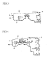
FIG. 3 is a sectional view taken along the line A-A ofFIG. 2 . -
FIG. 4 is a sectional view taken along the line B-B ofFIG. 2 . -
FIG. 5 is an enlarged view for illustrating a sealing portion ofFIG. 4 . - In the following, an embodiment of the present invention is described with reference to the drawings.
FIGS. 1 to 5 illustrate a vehicledoor lock device 100 according to the present invention. The vehicledoor lock device 100 is installed in adoor 201 mounted on a front right side of a vehicle. The vehicledoor lock device 100 includes alatch mechanism 10, alever mechanism 20, alink mechanism 30, and anelectric actuator 40, which are assembled to ahousing 50. - As is well known, the
latch mechanism 10 keeps thedoor 201 of the vehicle closed with respect to a body (vehicle body (not shown)) (keeps a state in which thedoor 201 is closed), and includes a latch 11 which is engageable with and disengageable from a striker (not shown) fixed to the body. Thelatch mechanism 10 is assembled to thedoor 201 under a state in which thelatch mechanism 10 is assembled to thehousing 50. - The
lever mechanism 20 includes an insideopen lever 21 which is driven in accordance with operation of an inside door handle (not shown) provided on an inner side of thedoor 201, and an outsideopen lever 22 which is driven in accordance with operation of an outside door handle (not shown) provided on an outer side of thedoor 201. The insideopen lever 21 is assembled to thehousing 50, and is linked with the inside door handle through the intermediation of anoperation cable 61 illustrated inFIG. 1 (operating force transmitting member such as a link may be used instead). Thus, the insideopen lever 21 is driven through the operation of the inside door handle. The outsideopen lever 22 is assembled to thehousing 50, and is linked with the outside door handle through the intermediation of an operating force transmitting member (not shown) such as a link. Thus, the outsideopen lever 22 is driven through the operation of the inside door handle. - The
link mechanism 30 is interposed in thehousing 50 between thelatch mechanism 10 and thelever mechanism 20, and includes anopen link 31 which can be switched between an unlock state in which transmission of an operating force from thelever mechanism 20 to thelatch mechanism 10 is enabled, and a lock state in which the transmission of the operating force is disabled. Theopen link 31 is interposed between the insideopen lever 21 provided to thelever mechanism 20 and a lift lever (not shown) provided to thelatch mechanism 10, and between the outsideopen lever 22 provided to thelever mechanism 20 and the lift lever. Theopen link 31 can be switched between an unlock position at which an action of eachopen lever open lever open lever - The
electric actuator 40 is assembled into thehousing 50, and can switch thelink mechanism 30 between the unlock state and the lock state. Theelectric actuator 40 includes anelectric motor 41, aworm 42, and a worm wheel 43, and further includes anactive lever 44 which is driven by those components. Note that, theactive lever 44 is coupled through the intermediation of anoperation cable 62 illustrated inFIG. 1 to a lock knob (not shown) provided to thedoor 201 on an inner side of the vehicle, and can be driven also through manual operation of the lock knob (not shown). Further, theactive lever 44 is coupled also to a key cylinder (not shown) provided on the outer side of thedoor 201, and can be driven also through manual operation of the key cylinder (not shown). - By the way, in this embodiment, the
housing 50 includes ahousing body 51 and ahousing cover 52 joined to each other, and is arranged so that a joining surface between thehousing body 51 and thehousing cover 52 extends along an up-and-down direction. Along a joining portion between thehousing body 51 and thehousing cover 52, a sealing portion S is formed so as to surround an upper part of an inner space R of the housing accommodating thelink mechanism 30 and theelectric actuator 40. - In the sealing portion S, there is formed a communication path P (see broken lines of
FIG. 1 ) which is formed along the joining portion, and includes one open end Pa and another closed end Pb. Further, as illustrated exaggeratedly inFIG. 5 , on an inner side of the housing and an outer side of the housing with respect to the communication path P, an inner welded portion Wi and an outer welded portion Wo are formed continuously along the communication path P, respectively. - As illustrated in
FIG. 5 , the communication path P includes acommunication groove 51 a formed in thehousing body 51 to have a rectangular cross-section, and anend wall 52a formed in thehousing cover 52 so as to close thecommunication groove 51a. Note that, the communication path (P) may include a communication groove formed in the housing cover (52), and an end wall formed in the housing body (51) so as to close the communication groove. - The inner welded portion Wi and the outer welded portion Wo are formed by laser welding. Further, the inner welded portion Wi and the outer welded portion Wo are connected to each other at the closed end Pb of the communication path P, and seal a periphery of the communication path P except the open end Pa of the communication path P airtightly and fluid-tightly. Further, in this embodiment, the
housing body 51 is made of a laser-beam-nontransmissive resin material, whereas thehousing cover 52 is made of a laser-beam-transmissive resin material. A laser beam having a light intensity necessary for desired laser welding is irradiated from thehousing cover 52 side. - In the vehicle
door lock device 100 according to this embodiment configured as described above, the sealing portion S formed along the joining portion between thehousing body 51 and thehousing cover 52 is configured as described above, and hence the above-mentioned sealing portion S prevents water, which falls from above to an upper portion of thehousing 50 and adheres thereto, from entering the inner space R of the housing accommodating thelink mechanism 30 and theelectric actuator 40. Therefore, in this embodiment, without use of a waterproof cover, thelink mechanism 30 and theelectric actuator 40 can be protected from the water with a simple and inexpensive configuration. - Further, in this embodiment, in the above-mentioned sealing portion S, the inner welded portion Wi and the outer welded portion Wo are formed continuously along the communication path P, and are connected to each other at the closed end Pb of the communication path P. Thus, the communication path P except the open end Pa is sealed by the inner welded portion Wi and the outer welded portion Wo airtightly and fluid-tightly. Accordingly, it is possible to charge pressurized gas (for example, compressed air) into the communication path P from the open end portion of the communication path P, and through connecting a connection tool (not shown) capable of examining the gas pressure to the open end portion of the communication path P, it is possible to easily determine whether or not the above-mentioned sealing portion S maintains satisfactory sealing properties (airtightness and fluid-tightness).
- Further, in this embodiment, the communication path P includes the
communication groove 51a formed in thehousing body 51, and theend wall 52a formed in thehousing cover 52 so as to close thecommunication groove 51 a, and hence the communication path S can be formed simply at low cost. Further, the inner welded portion Wi and the outer welded portion Wo are formed by laser welding, and hence in comparison to a case where the inner welded portion Wi and the outer welded portion Wo are formed by vibration welding, it is possible to suppress influence on components accommodated in thehousing 50. - In the above-mentioned embodiment, the present invention is carried out in such a manner that the communication path P is shaped to include the one open end Pa and the another closed end Pb, but may be carried out in such a manner that the communication path (P) is shaped to include both ends that are open downward. In this case, even if water flows through the outer welded portion (Wo) toward the housing (50), the water is trapped in the communication path (P) and is prevented from entering the upper part of the inner space (R) of the housing. Further, the water trapped in the communication path (P) drips down from the end portion of the communication path (P), and hence does not enter the upper part of the inner space (R) of the housing. Therefore, water falling from above can be appropriately prevented from entering the upper part of the inner space (R) of the housing.
Claims (6)
- A vehicle door lock device, comprising:a latch mechanism, which is capable of keeping a door of a vehicle closed with respect to a body, and is adapted to be assembled to the door together with a housing;a lever mechanism, which is adapted to be assembled to the housing, and to be driven through operation of a door handle provided to the door;a link mechanism, which is interposed in the housing between the latch mechanism and the lever mechanism, and is capable of being switched between an unlock state in which transmission of an operating force from the lever mechanism to the latch mechanism is enabled, and a lock state in which the transmission of the operating force is disabled; andan electric actuator, which is assembled into the housing, and switches the link mechanism between the unlock state and the lock state;wherein the housing comprises a housing body and a housing cover joined to each other, and is arranged so that a joining surface between the housing body and the housing cover extends along an up-and-down direction,wherein a sealing portion is formed along a joining portion between the housing body and the housing cover so as to surround an upper part of an inner space of the housing accommodating the link mechanism and the electric actuator, andwherein the sealing portion comprises:a communication path, which is formed along the joining portion, and comprises at least one open end; andan inner welded portion and an outer welded portion, which are formed continuously along the communication path on an inner side of the housing and an outer side of the housing with respect to the communication path, respectively.
- A vehicle door lock device according to claim 1, wherein the communication path comprises:a communication groove formed in one of the housing body and the housing cover; andan end wall formed in another one of the housing body and the housing cover so as to close the communication groove.
- A vehicle door lock device according to claim 1 or 2, wherein the inner welded portion and the outer welded portion are formed by laser welding.
- A vehicle door lock device according to claim 3,
wherein the housing body is made of a laser-beam-nontransmissive resin material,
wherein the housing cover is made of a laser-beam-transmissive resin material, and
wherein the inner welded portion and the outer welded portion are subjected to the laser welding through irradiation of a laser beam from the housing cover side. - A vehicle door lock device according to any one of claims 1 to 4,
wherein the communication path comprises one open end and another closed end, and
wherein the inner welded portion and the outer welded portion are connected to each other at the another closed end. - A vehicle door lock device according to any one of claims 1 to 4, wherein the communication path comprises both ends that are open downward.
Applications Claiming Priority (2)
| Application Number | Priority Date | Filing Date | Title |
|---|---|---|---|
| JP2010098734A JP5365574B2 (en) | 2010-04-22 | 2010-04-22 | Vehicle door lock device |
| PCT/JP2011/055632 WO2011132474A1 (en) | 2010-04-22 | 2011-03-10 | Vehicle door lock device |
Publications (3)
| Publication Number | Publication Date |
|---|---|
| EP2562336A1 true EP2562336A1 (en) | 2013-02-27 |
| EP2562336A4 EP2562336A4 (en) | 2013-07-03 |
| EP2562336B1 EP2562336B1 (en) | 2014-04-23 |
Family
ID=44834013
Family Applications (1)
| Application Number | Title | Priority Date | Filing Date |
|---|---|---|---|
| EP20110771814 Not-in-force EP2562336B1 (en) | 2010-04-22 | 2011-03-10 | Vehicle door lock device |
Country Status (6)
| Country | Link |
|---|---|
| US (1) | US20130015673A1 (en) |
| EP (1) | EP2562336B1 (en) |
| JP (1) | JP5365574B2 (en) |
| CN (1) | CN102822434A (en) |
| BR (1) | BR112012026905A2 (en) |
| WO (1) | WO2011132474A1 (en) |
Cited By (2)
| Publication number | Priority date | Publication date | Assignee | Title |
|---|---|---|---|---|
| JP2013189822A (en) * | 2012-03-14 | 2013-09-26 | Aisin Kiko Co Ltd | Wall body fastening part structure and manufacturing method of vehicle component |
| CN113474528A (en) * | 2019-07-31 | 2021-10-01 | 三井金属爱科特株式会社 | Door lock device |
Families Citing this family (20)
| Publication number | Priority date | Publication date | Assignee | Title |
|---|---|---|---|---|
| JP5546521B2 (en) * | 2011-11-01 | 2014-07-09 | アイシン機工株式会社 | Door lock device |
| CN105658889B (en) * | 2013-09-25 | 2018-10-19 | 麦格纳覆盖件有限公司 | Electric vehicle latche |
| CN104963570B (en) * | 2014-02-14 | 2018-05-01 | 因特瓦产品有限责任公司 | The lock bolt housing of attachment structure with one |
| JP6454908B2 (en) * | 2014-07-18 | 2019-01-23 | 三井金属アクト株式会社 | Vehicle door latch device |
| JP6515303B2 (en) * | 2015-07-07 | 2019-05-22 | 三井金属アクト株式会社 | Vehicle door lock device |
| JP6572486B2 (en) * | 2016-02-26 | 2019-09-11 | 三井金属アクト株式会社 | Door lock device and manufacturing method thereof |
| DE102016206400A1 (en) * | 2016-04-15 | 2017-10-19 | Bühler Motor GmbH | Actuator and method for producing an actuator |
| CN107620529B (en) | 2016-07-15 | 2020-12-15 | 株式会社安成 | Door lock device for vehicle |
| JP6652709B2 (en) * | 2016-07-15 | 2020-02-26 | 株式会社アンセイ | Vehicle door lock device |
| JP6627671B2 (en) * | 2016-07-15 | 2020-01-08 | 株式会社アンセイ | Vehicle door lock device |
| JP6627672B2 (en) | 2016-07-20 | 2020-01-08 | 株式会社アンセイ | Vehicle door lock device |
| JP6627729B2 (en) | 2016-11-25 | 2020-01-08 | 株式会社アンセイ | Vehicle door lock device |
| JP6762242B2 (en) * | 2017-01-30 | 2020-09-30 | ジーコム コーポレイションGecom Corporation | Vehicle door latch device |
| JP6772215B2 (en) * | 2018-05-28 | 2020-10-21 | 三井金属アクト株式会社 | Door lock device vs. |
| JP6627920B2 (en) | 2018-06-26 | 2020-01-08 | 株式会社アンセイ | Vehicle door lock device |
| DE102020118721A1 (en) * | 2020-07-15 | 2022-01-20 | Kiekert Aktiengesellschaft | motor vehicle lock |
| DE102020132170A1 (en) | 2020-12-03 | 2022-06-09 | Brose Schließsysteme GmbH & Co. Kommanditgesellschaft | Functional unit for actuating a motor vehicle lock |
| DE102021121544A1 (en) * | 2021-08-19 | 2023-02-23 | Kiekert Aktiengesellschaft | Electromotive actuating device for motor vehicle applications |
| DE102021132129A1 (en) * | 2021-12-07 | 2023-06-07 | Kiekert Aktiengesellschaft | Actuator for automotive applications |
| JP7827980B2 (en) | 2022-06-06 | 2026-03-11 | 株式会社アンセイ | Locking device for vehicle opening/closing body |
Family Cites Families (8)
| Publication number | Priority date | Publication date | Assignee | Title |
|---|---|---|---|---|
| JP3079611B2 (en) * | 1991-03-29 | 2000-08-21 | アイシン精機株式会社 | Ridlock device |
| FR2783551B1 (en) * | 1998-09-21 | 2000-11-17 | Valeo Securite Habitacle | IMPROVED ELECTRIC LOCK FOR A MOTOR VEHICLE DOOR |
| JP2004251106A (en) * | 2003-01-30 | 2004-09-09 | Aisin Seiki Co Ltd | Door lock device |
| JP2006233506A (en) | 2005-02-23 | 2006-09-07 | Aisin Seiki Co Ltd | Door lock device |
| JP4856504B2 (en) * | 2006-09-11 | 2012-01-18 | 三井金属アクト株式会社 | Actuator unit |
| US20100072761A1 (en) * | 2008-02-04 | 2010-03-25 | Kris Tomaszewski | Global Side Door Latch |
| JP4542166B2 (en) * | 2008-03-26 | 2010-09-08 | 三井金属鉱業株式会社 | Door lock device |
| DE202008004332U1 (en) * | 2008-03-29 | 2009-08-06 | Kiekert Ag | Motor vehicle door lock |
-
2010
- 2010-04-22 JP JP2010098734A patent/JP5365574B2/en not_active Expired - Fee Related
-
2011
- 2011-03-10 CN CN2011800159807A patent/CN102822434A/en active Pending
- 2011-03-10 BR BR112012026905A patent/BR112012026905A2/en not_active Application Discontinuation
- 2011-03-10 WO PCT/JP2011/055632 patent/WO2011132474A1/en not_active Ceased
- 2011-03-10 US US13/637,183 patent/US20130015673A1/en not_active Abandoned
- 2011-03-10 EP EP20110771814 patent/EP2562336B1/en not_active Not-in-force
Cited By (2)
| Publication number | Priority date | Publication date | Assignee | Title |
|---|---|---|---|---|
| JP2013189822A (en) * | 2012-03-14 | 2013-09-26 | Aisin Kiko Co Ltd | Wall body fastening part structure and manufacturing method of vehicle component |
| CN113474528A (en) * | 2019-07-31 | 2021-10-01 | 三井金属爱科特株式会社 | Door lock device |
Also Published As
| Publication number | Publication date |
|---|---|
| JP5365574B2 (en) | 2013-12-11 |
| CN102822434A (en) | 2012-12-12 |
| EP2562336A4 (en) | 2013-07-03 |
| WO2011132474A1 (en) | 2011-10-27 |
| JP2011226194A (en) | 2011-11-10 |
| US20130015673A1 (en) | 2013-01-17 |
| EP2562336B1 (en) | 2014-04-23 |
| BR112012026905A2 (en) | 2016-07-12 |
Similar Documents
| Publication | Publication Date | Title |
|---|---|---|
| EP2562336B1 (en) | Vehicle door lock device | |
| US5902004A (en) | Motor vehicle door | |
| US11428032B2 (en) | Lock for a motor vehicle | |
| JP6260874B2 (en) | Push button switch device for vehicle | |
| US8496074B2 (en) | Power tool | |
| JP2011226194A5 (en) | ||
| US20130023141A1 (en) | Charging coupling and charging coupling arrangement for a motor vehicle, and motor vehicle | |
| US12410642B2 (en) | Motor vehicle lock housing arrangement | |
| CN203219652U (en) | Gearing housing and driving device for vehicle adjusting element | |
| US9908556B2 (en) | Receptacle for a control circuit that controls an electric motor for power assistance in a vehicle steering system | |
| EP1703047B1 (en) | Door lock apparatus | |
| EP2620569B1 (en) | Latch releasing system for vehicle door | |
| US11239601B2 (en) | Housing for use in motor vehicles | |
| CN107849874B (en) | Door locking device for vehicles | |
| EP1538284A2 (en) | Actuator and vehicle-mounted electrically operated device having the same | |
| US12297674B2 (en) | Motor vehicle latch, in particular a motor vehicle door latch | |
| CN110546821A (en) | Connector with a locking member | |
| US7758098B2 (en) | Device for making accessible and closing an opening in a vehicle body | |
| US11688567B2 (en) | Waterproof switch assembly | |
| CA2489465A1 (en) | A lock for a door of a motor vehicle | |
| CN1898453B (en) | Rotary door operator | |
| CN107871630A (en) | Push button switch device for vehicles | |
| US20240006818A1 (en) | Socket with an actuator for guiding a locking element | |
| KR100826626B1 (en) | Door Locking Device Using Electromagnet | |
| JP2018040195A (en) | Door latch device for vehicle |
Legal Events
| Date | Code | Title | Description |
|---|---|---|---|
| PUAI | Public reference made under article 153(3) epc to a published international application that has entered the european phase |
Free format text: ORIGINAL CODE: 0009012 |
|
| 17P | Request for examination filed |
Effective date: 20121004 |
|
| AK | Designated contracting states |
Kind code of ref document: A1 Designated state(s): AL AT BE BG CH CY CZ DE DK EE ES FI FR GB GR HR HU IE IS IT LI LT LU LV MC MK MT NL NO PL PT RO RS SE SI SK SM TR |
|
| A4 | Supplementary search report drawn up and despatched |
Effective date: 20130604 |
|
| RIC1 | Information provided on ipc code assigned before grant |
Ipc: E05B 65/20 20060101AFI20130528BHEP |
|
| DAX | Request for extension of the european patent (deleted) | ||
| GRAP | Despatch of communication of intention to grant a patent |
Free format text: ORIGINAL CODE: EPIDOSNIGR1 |
|
| INTG | Intention to grant announced |
Effective date: 20131011 |
|
| RIN1 | Information on inventor provided before grant (corrected) |
Inventor name: WATANABE, NOBUKO Inventor name: SONO, YASUHIKO Inventor name: NISHIO, TAKASHI Inventor name: AKIZUKI, RYUJIRO Inventor name: KOJIMA, KAZUNORI |
|
| GRAS | Grant fee paid |
Free format text: ORIGINAL CODE: EPIDOSNIGR3 |
|
| RIN1 | Information on inventor provided before grant (corrected) |
Inventor name: SONO, YASUHIKO Inventor name: KOJIMA, KAZUNORI Inventor name: AKIZUKI, RYUJIRO Inventor name: NISHIO, TAKASHI Inventor name: WATANABE, NOBUKO |
|
| REG | Reference to a national code |
Ref country code: DE Ref legal event code: R079 Ref document number: 602011006440 Country of ref document: DE Free format text: PREVIOUS MAIN CLASS: E05B0065200000 Ipc: E05B0085020000 |
|
| GRAA | (expected) grant |
Free format text: ORIGINAL CODE: 0009210 |
|
| AK | Designated contracting states |
Kind code of ref document: B1 Designated state(s): AL AT BE BG CH CY CZ DE DK EE ES FI FR GB GR HR HU IE IS IT LI LT LU LV MC MK MT NL NO PL PT RO RS SE SI SK SM TR |
|
| REG | Reference to a national code |
Ref country code: GB Ref legal event code: FG4D |
|
| RIC1 | Information provided on ipc code assigned before grant |
Ipc: E05B 77/34 20140101ALI20140319BHEP Ipc: E05B 85/02 20140101AFI20140319BHEP |
|
| REG | Reference to a national code |
Ref country code: CH Ref legal event code: EP |
|
| REG | Reference to a national code |
Ref country code: AT Ref legal event code: REF Ref document number: 663983 Country of ref document: AT Kind code of ref document: T Effective date: 20140515 |
|
| REG | Reference to a national code |
Ref country code: IE Ref legal event code: FG4D |
|
| REG | Reference to a national code |
Ref country code: DE Ref legal event code: R096 Ref document number: 602011006440 Country of ref document: DE Effective date: 20140605 |
|
| REG | Reference to a national code |
Ref country code: AT Ref legal event code: MK05 Ref document number: 663983 Country of ref document: AT Kind code of ref document: T Effective date: 20140423 |
|
| REG | Reference to a national code |
Ref country code: NL Ref legal event code: VDEP Effective date: 20140423 |
|
| REG | Reference to a national code |
Ref country code: LT Ref legal event code: MG4D |
|
| PG25 | Lapsed in a contracting state [announced via postgrant information from national office to epo] |
Ref country code: LT Free format text: LAPSE BECAUSE OF FAILURE TO SUBMIT A TRANSLATION OF THE DESCRIPTION OR TO PAY THE FEE WITHIN THE PRESCRIBED TIME-LIMIT Effective date: 20140423 Ref country code: GR Free format text: LAPSE BECAUSE OF FAILURE TO SUBMIT A TRANSLATION OF THE DESCRIPTION OR TO PAY THE FEE WITHIN THE PRESCRIBED TIME-LIMIT Effective date: 20140724 Ref country code: FI Free format text: LAPSE BECAUSE OF FAILURE TO SUBMIT A TRANSLATION OF THE DESCRIPTION OR TO PAY THE FEE WITHIN THE PRESCRIBED TIME-LIMIT Effective date: 20140423 Ref country code: NL Free format text: LAPSE BECAUSE OF FAILURE TO SUBMIT A TRANSLATION OF THE DESCRIPTION OR TO PAY THE FEE WITHIN THE PRESCRIBED TIME-LIMIT Effective date: 20140423 Ref country code: BG Free format text: LAPSE BECAUSE OF FAILURE TO SUBMIT A TRANSLATION OF THE DESCRIPTION OR TO PAY THE FEE WITHIN THE PRESCRIBED TIME-LIMIT Effective date: 20140723 Ref country code: CY Free format text: LAPSE BECAUSE OF FAILURE TO SUBMIT A TRANSLATION OF THE DESCRIPTION OR TO PAY THE FEE WITHIN THE PRESCRIBED TIME-LIMIT Effective date: 20140423 Ref country code: IS Free format text: LAPSE BECAUSE OF FAILURE TO SUBMIT A TRANSLATION OF THE DESCRIPTION OR TO PAY THE FEE WITHIN THE PRESCRIBED TIME-LIMIT Effective date: 20140823 Ref country code: NO Free format text: LAPSE BECAUSE OF FAILURE TO SUBMIT A TRANSLATION OF THE DESCRIPTION OR TO PAY THE FEE WITHIN THE PRESCRIBED TIME-LIMIT Effective date: 20140723 |
|
| PG25 | Lapsed in a contracting state [announced via postgrant information from national office to epo] |
Ref country code: HR Free format text: LAPSE BECAUSE OF FAILURE TO SUBMIT A TRANSLATION OF THE DESCRIPTION OR TO PAY THE FEE WITHIN THE PRESCRIBED TIME-LIMIT Effective date: 20140423 Ref country code: RS Free format text: LAPSE BECAUSE OF FAILURE TO SUBMIT A TRANSLATION OF THE DESCRIPTION OR TO PAY THE FEE WITHIN THE PRESCRIBED TIME-LIMIT Effective date: 20140423 Ref country code: ES Free format text: LAPSE BECAUSE OF FAILURE TO SUBMIT A TRANSLATION OF THE DESCRIPTION OR TO PAY THE FEE WITHIN THE PRESCRIBED TIME-LIMIT Effective date: 20140423 Ref country code: PL Free format text: LAPSE BECAUSE OF FAILURE TO SUBMIT A TRANSLATION OF THE DESCRIPTION OR TO PAY THE FEE WITHIN THE PRESCRIBED TIME-LIMIT Effective date: 20140423 Ref country code: SE Free format text: LAPSE BECAUSE OF FAILURE TO SUBMIT A TRANSLATION OF THE DESCRIPTION OR TO PAY THE FEE WITHIN THE PRESCRIBED TIME-LIMIT Effective date: 20140423 Ref country code: AT Free format text: LAPSE BECAUSE OF FAILURE TO SUBMIT A TRANSLATION OF THE DESCRIPTION OR TO PAY THE FEE WITHIN THE PRESCRIBED TIME-LIMIT Effective date: 20140423 Ref country code: LV Free format text: LAPSE BECAUSE OF FAILURE TO SUBMIT A TRANSLATION OF THE DESCRIPTION OR TO PAY THE FEE WITHIN THE PRESCRIBED TIME-LIMIT Effective date: 20140423 |
|
| PG25 | Lapsed in a contracting state [announced via postgrant information from national office to epo] |
Ref country code: PT Free format text: LAPSE BECAUSE OF FAILURE TO SUBMIT A TRANSLATION OF THE DESCRIPTION OR TO PAY THE FEE WITHIN THE PRESCRIBED TIME-LIMIT Effective date: 20140825 |
|
| REG | Reference to a national code |
Ref country code: DE Ref legal event code: R097 Ref document number: 602011006440 Country of ref document: DE |
|
| PG25 | Lapsed in a contracting state [announced via postgrant information from national office to epo] |
Ref country code: BE Free format text: LAPSE BECAUSE OF FAILURE TO SUBMIT A TRANSLATION OF THE DESCRIPTION OR TO PAY THE FEE WITHIN THE PRESCRIBED TIME-LIMIT Effective date: 20140423 Ref country code: RO Free format text: LAPSE BECAUSE OF FAILURE TO SUBMIT A TRANSLATION OF THE DESCRIPTION OR TO PAY THE FEE WITHIN THE PRESCRIBED TIME-LIMIT Effective date: 20140423 Ref country code: DK Free format text: LAPSE BECAUSE OF FAILURE TO SUBMIT A TRANSLATION OF THE DESCRIPTION OR TO PAY THE FEE WITHIN THE PRESCRIBED TIME-LIMIT Effective date: 20140423 Ref country code: EE Free format text: LAPSE BECAUSE OF FAILURE TO SUBMIT A TRANSLATION OF THE DESCRIPTION OR TO PAY THE FEE WITHIN THE PRESCRIBED TIME-LIMIT Effective date: 20140423 Ref country code: SK Free format text: LAPSE BECAUSE OF FAILURE TO SUBMIT A TRANSLATION OF THE DESCRIPTION OR TO PAY THE FEE WITHIN THE PRESCRIBED TIME-LIMIT Effective date: 20140423 Ref country code: CZ Free format text: LAPSE BECAUSE OF FAILURE TO SUBMIT A TRANSLATION OF THE DESCRIPTION OR TO PAY THE FEE WITHIN THE PRESCRIBED TIME-LIMIT Effective date: 20140423 |
|
| PLBE | No opposition filed within time limit |
Free format text: ORIGINAL CODE: 0009261 |
|
| STAA | Information on the status of an ep patent application or granted ep patent |
Free format text: STATUS: NO OPPOSITION FILED WITHIN TIME LIMIT |
|
| PG25 | Lapsed in a contracting state [announced via postgrant information from national office to epo] |
Ref country code: IT Free format text: LAPSE BECAUSE OF FAILURE TO SUBMIT A TRANSLATION OF THE DESCRIPTION OR TO PAY THE FEE WITHIN THE PRESCRIBED TIME-LIMIT Effective date: 20140423 |
|
| 26N | No opposition filed |
Effective date: 20150126 |
|
| REG | Reference to a national code |
Ref country code: DE Ref legal event code: R097 Ref document number: 602011006440 Country of ref document: DE Effective date: 20150126 |
|
| PG25 | Lapsed in a contracting state [announced via postgrant information from national office to epo] |
Ref country code: SI Free format text: LAPSE BECAUSE OF FAILURE TO SUBMIT A TRANSLATION OF THE DESCRIPTION OR TO PAY THE FEE WITHIN THE PRESCRIBED TIME-LIMIT Effective date: 20140423 |
|
| REG | Reference to a national code |
Ref country code: DE Ref legal event code: R119 Ref document number: 602011006440 Country of ref document: DE |
|
| PG25 | Lapsed in a contracting state [announced via postgrant information from national office to epo] |
Ref country code: MC Free format text: LAPSE BECAUSE OF FAILURE TO SUBMIT A TRANSLATION OF THE DESCRIPTION OR TO PAY THE FEE WITHIN THE PRESCRIBED TIME-LIMIT Effective date: 20140423 Ref country code: LU Free format text: LAPSE BECAUSE OF FAILURE TO SUBMIT A TRANSLATION OF THE DESCRIPTION OR TO PAY THE FEE WITHIN THE PRESCRIBED TIME-LIMIT Effective date: 20150310 |
|
| REG | Reference to a national code |
Ref country code: CH Ref legal event code: PL |
|
| GBPC | Gb: european patent ceased through non-payment of renewal fee |
Effective date: 20150310 |
|
| REG | Reference to a national code |
Ref country code: FR Ref legal event code: ST Effective date: 20151130 |
|
| REG | Reference to a national code |
Ref country code: IE Ref legal event code: MM4A |
|
| PG25 | Lapsed in a contracting state [announced via postgrant information from national office to epo] |
Ref country code: CH Free format text: LAPSE BECAUSE OF NON-PAYMENT OF DUE FEES Effective date: 20150331 Ref country code: LI Free format text: LAPSE BECAUSE OF NON-PAYMENT OF DUE FEES Effective date: 20150331 Ref country code: DE Free format text: LAPSE BECAUSE OF NON-PAYMENT OF DUE FEES Effective date: 20151001 Ref country code: GB Free format text: LAPSE BECAUSE OF NON-PAYMENT OF DUE FEES Effective date: 20150310 Ref country code: IE Free format text: LAPSE BECAUSE OF NON-PAYMENT OF DUE FEES Effective date: 20150310 |
|
| PG25 | Lapsed in a contracting state [announced via postgrant information from national office to epo] |
Ref country code: FR Free format text: LAPSE BECAUSE OF NON-PAYMENT OF DUE FEES Effective date: 20150331 |
|
| PG25 | Lapsed in a contracting state [announced via postgrant information from national office to epo] |
Ref country code: MT Free format text: LAPSE BECAUSE OF FAILURE TO SUBMIT A TRANSLATION OF THE DESCRIPTION OR TO PAY THE FEE WITHIN THE PRESCRIBED TIME-LIMIT Effective date: 20140423 |
|
| PG25 | Lapsed in a contracting state [announced via postgrant information from national office to epo] |
Ref country code: SM Free format text: LAPSE BECAUSE OF FAILURE TO SUBMIT A TRANSLATION OF THE DESCRIPTION OR TO PAY THE FEE WITHIN THE PRESCRIBED TIME-LIMIT Effective date: 20140423 Ref country code: HU Free format text: LAPSE BECAUSE OF FAILURE TO SUBMIT A TRANSLATION OF THE DESCRIPTION OR TO PAY THE FEE WITHIN THE PRESCRIBED TIME-LIMIT; INVALID AB INITIO Effective date: 20110310 |
|
| PG25 | Lapsed in a contracting state [announced via postgrant information from national office to epo] |
Ref country code: TR Free format text: LAPSE BECAUSE OF FAILURE TO SUBMIT A TRANSLATION OF THE DESCRIPTION OR TO PAY THE FEE WITHIN THE PRESCRIBED TIME-LIMIT Effective date: 20140423 |
|
| PG25 | Lapsed in a contracting state [announced via postgrant information from national office to epo] |
Ref country code: MK Free format text: LAPSE BECAUSE OF FAILURE TO SUBMIT A TRANSLATION OF THE DESCRIPTION OR TO PAY THE FEE WITHIN THE PRESCRIBED TIME-LIMIT Effective date: 20140423 |
|
| PG25 | Lapsed in a contracting state [announced via postgrant information from national office to epo] |
Ref country code: AL Free format text: LAPSE BECAUSE OF FAILURE TO SUBMIT A TRANSLATION OF THE DESCRIPTION OR TO PAY THE FEE WITHIN THE PRESCRIBED TIME-LIMIT Effective date: 20140423 |