EP2561978A2 - Verfahren und Vorrichtung zum Formpressen und Härten von Verbundstoffen - Google Patents
Verfahren und Vorrichtung zum Formpressen und Härten von Verbundstoffen Download PDFInfo
- Publication number
- EP2561978A2 EP2561978A2 EP12180610A EP12180610A EP2561978A2 EP 2561978 A2 EP2561978 A2 EP 2561978A2 EP 12180610 A EP12180610 A EP 12180610A EP 12180610 A EP12180610 A EP 12180610A EP 2561978 A2 EP2561978 A2 EP 2561978A2
- Authority
- EP
- European Patent Office
- Prior art keywords
- elastic layer
- mold
- molding
- fluid
- composite article
- Prior art date
- Legal status (The legal status is an assumption and is not a legal conclusion. Google has not performed a legal analysis and makes no representation as to the accuracy of the status listed.)
- Granted
Links
Images
Classifications
-
- B—PERFORMING OPERATIONS; TRANSPORTING
- B29—WORKING OF PLASTICS; WORKING OF SUBSTANCES IN A PLASTIC STATE IN GENERAL
- B29C—SHAPING OR JOINING OF PLASTICS; SHAPING OF MATERIAL IN A PLASTIC STATE, NOT OTHERWISE PROVIDED FOR; AFTER-TREATMENT OF THE SHAPED PRODUCTS, e.g. REPAIRING
- B29C70/00—Shaping composites, i.e. plastics material comprising reinforcements, fillers or preformed parts, e.g. inserts
- B29C70/04—Shaping composites, i.e. plastics material comprising reinforcements, fillers or preformed parts, e.g. inserts comprising reinforcements only, e.g. self-reinforcing plastics
- B29C70/28—Shaping operations therefor
- B29C70/40—Shaping or impregnating by compression not applied
- B29C70/42—Shaping or impregnating by compression not applied for producing articles of definite length, i.e. discrete articles
- B29C70/44—Shaping or impregnating by compression not applied for producing articles of definite length, i.e. discrete articles using isostatic pressure, e.g. pressure difference-moulding, vacuum bag-moulding, autoclave-moulding or expanding rubber-moulding
Definitions
- the present disclosure relates generally to methods and apparatus for molding and curing of composites. More particularly, the present disclosure relates to methods and apparatus for pressurized molding and curing of composites.
- Composite materials may be typically used in aerospace applications, marine applications, wind turbine applications, and other applications where high strength and relatively light weight may be desired.
- Composites typically include reinforcing material (for example, fibers) and a matrix (for example, polymer) as the two principal elements.
- the matrix may include thermosets or thermoplastic materials.
- Composite materials may be formed into the desired components by molding and subsequent curing.
- a molded composite is formed using a mold and then transferred to an autoclave for curing, where a combination of heat and pressure is applied to the molded composite.
- processing large and/or thick solid composite parts, such as wind energy turbine blades may not be feasible or easily managed in an autoclave.
- the molding and subsequent curing in an autoclave may require the additional step of transferring the molded composite to an autoclave.
- a method of manufacturing a cured composite article includes providing a molding apparatus including an elastic layer disposed on a rigid support and a mold disposed on the elastic layer and the support.
- the mold includes an inner surface, the inner surface further including a molding surface, and wherein a first surface of the elastic layer and the inner surface of the mold define a molding chamber.
- a prepreg is further disposed within the molding chamber, wherein the prepreg is disposed on the first surface of the elastic layer.
- the method includes providing a fluid via a fluid inlet against a second surface of the elastic layer, thereby expanding the elastic layer against the inner surface of the mold, and pushing the prepreg against the molding surface of the mold to form a molded composite article. In one embodiment, the method further includes curing the molded composite article in the molding chamber to form a cured composite article.
- a method of manufacturing a cured composite article includes providing a molding apparatus including an elastic layer disposed on a rigid support and a mold disposed on the elastic layer and the support.
- the mold includes an inner surface, the inner surface further including a molding surface, and wherein a first surface of the elastic layer and the inner surface of the mold define a molding chamber.
- a prepreg is further disposed within the molding chamber, wherein the prepreg is disposed on the first surface of the elastic layer.
- the method includes providing a fluid via a fluid inlet against a second surface of the elastic layer, thereby expanding the elastic layer against the inner surface of the mold, and pushing the prepreg against the molding surface of the mold to form a molded composite article.
- the method further includes applying a positive pressure to the fluid and heating the fluid to a cure temperature, thereby curing the molded composite article in the molding chamber to form a cured composite article.
- an apparatus for manufacturing a cured composite article includes an elastic layer disposed on a rigid support and a mold disposed on the elastic layer and the support.
- the mold includes an inner surface, the inner surface further including a molding surface, and wherein a first surface of the elastic layer and the inner surface of the mold define a molding chamber.
- the molding chamber is configured to receive a prepreg disposed on the first surface of the elastic layer.
- the apparatus further includes at least one fluid port configured to provide a fluid against a second surface of the elastic layer, thereby expanding the elastic layer against the inner surface of the mold, and pushing the prepreg against the molding surface of the mold to form a molded composite article.
- the apparatus further includes at least one heating element configured to cure the molded composite article and form the cured composite article.
- embodiments of the present invention include methods and apparatus suitable for molding and curing of composites.
- the methods and apparatus of the present invention advantageously allow for continuous molding and curing in the molding apparatus and may obviate the step of transferring the molded component to a curing system.
- the methods and apparatus of the present invention advantageously allow for molding and curing of the composite in the molding apparatus itself and obviate the use of autoclaves.
- Approximating language may be applied to modify any quantitative representation that could permissibly vary without resulting in a change in the basic function to which it is related. Accordingly, a value modified by a term or terms, such as "about”, is not limited to the precise value specified. In some instances, the approximating language may correspond to the precision of an instrument for measuring the value.
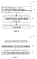
- a method 10 for manufacturing a cured composite article includes, at step 11, providing a molding apparatus 100.
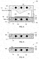
- the molding apparatus 100 includes an elastic layer 120 disposed on a rigid support 110, as indicated in Fig. 4 .
- Fig. 5 further illustrates a disassembled molding apparatus showing an enlarged side-view of the elastic layer 120 disposed on the rigid support 110.
- the elastic layer includes a first surface 121 and a second surface 122, in one embodiment.
- the rigid support 110 includes a first surface 111 and a second surface 112.
- a second surface 122 of the elastic layer 120 is disposed on the first surface 111 of the rigid support 110, in one embodiment.
- the second surface 122 of the elastic layer 120 is disposed such that the second surface 122 is contiguous to or in direct contact with the first surface 111 of the rigid support 110, as indicated in Fig. 5 . In some other embodiments, the second surface 122 of the elastic layer 120 is disposed such that there is a gap between the second surface 122 of the elastic layer 120 and the first surface 111 of the rigid support 110. In such embodiments, the second surface 122 of the elastic layer 120 and the first surface 111 of the rigid support 110 define a volume (not shown). In some embodiments, as described herein later, the volume is configured to receive a fluid.
- the rigid support 110 may have a size and configuration suitable to support a mold 140 and the composite article to be molded, as described herein later.
- the dimensions (width and length) of the rigid support 110 may be chosen to be in accordance with the dimensions of the composite article being molded.
- the molding apparatus 100 may be advantageously used to mold large composite articles. Accordingly, the first surface 111 of the rigid support 110 may be quite large and range from a few square feet to hundreds of square feet, in some embodiments.
- the rigid support 110 may include an inflexible material.
- the rigid support may include steel alloys typically used to make autoclaves and pressurized molds.
- the rigid support may include a composite material, such that that the material is sufficiently rigid to withstand the pressurization force exerted during the molding step.
- the rigid support 110 includes an inflexible or rigid surface 111 on which the elastic layer 120 is disposed.
- the first surface 111 may be flat, as indicated in Fig. 5 .
- the first surface 111 may be curved or similar shape (not shown).
- the rigid support 110 may include a table having a substantially flat surface 111.
- the rigid support 110 may further include one or more ports.
- one or more of the ports may be suitable as vacuum ports, ports for thermocouples, sensor leads, ports for resin infusion, ports for circulation of heating or cooling fluids, or as ports for heating or cooling devices.
- the ports may be located in the rigid support 110 to avoid interference with the elastic layer 120 and the mold 140.
- the rigid support 110 includes at least one fluid inlet 160, as described herein later.
- the term "elastic layer” as used herein refers to a layer that is capable of returning to its original shape or size after being stretched, deformed, compressed, or expanded.
- the elastic layer 120 may be capable of stretching from 100% to 800% of its original size.
- the elastic layer 120 may be capable of stretching from 100% to 600% of its original size.
- the elastic layer 120 may be capable of stretching from 100% to 500% of its original size.
- the width and length of the elastic layer 120 in a relaxed state is chosen to match the rigid support 110.
- the thickness of the elastic layer 120 may be varied depending upon the particular elastic material used and the expected pressure levels in the apparatus, in some embodiments.
- the elastic layer 120 includes a strong, elastic material that is impermeable to gas, fluid, or both.
- the elastic layer 120 includes thermosets, such as, silicone, neoprene, SBR, butyl or nitrile rubbers.
- the elastic layer 120 includes flexible thermoplastic materials, such as, nylon, polypropylene, or polyethylene.
- the molding apparatus 100 further includes a mold 140 disposed on the elastic layer 120 and the support 110, as indicated in Fig. 4 .
- the mold 140 includes an inner surface 141, as indicated in Fig. 4 .
- the inner surface 141 of the mold 140 further includes a portion that defines a molding surface 142.
- the mold's inner surface 141 may be machined or otherwise shaped to provide a molding surface or contour 142.
- the molding surface 142 may include a convex or a concave profile.
- the molding surface or contour 142 includes a profile in accordance with the composite article to be molded.
- the mold 140 may have a size and configuration suitable for the composite article to be molded, as described herein later.
- the dimensions (width and length) of the mold 140 may be chosen to be in accordance with the dimensions of the composite article being molded.
- the molding apparatus 100 may be advantageously used to mold large composite articles. Accordingly, the inner surface 141 of the mold 140 may be quite large and range from a few square feet to hundreds of square feet, in some embodiments.
- the mold 140 may include an inflexible material.
- the mold 140 may include steel alloys typically used to make autoclaves and pressurized molds.
- the mold 140 may include a composite material, such that that the material is sufficiently rigid to withstand the pressurization force exerted during the molding step.
- the mold 140 may further include one or more ports.
- one or more of the ports may be suitable as vacuum ports, ports for thermocouples, sensor leads, ports for circulation of heating or cooling fluids, or as ports for heating or cooling devices.
- the ports may be located in the mold 140 to avoid interference with the elastic layer 120 and the prepreg 200, as described herein later.
- the mold 140 includes at least one vacuum port 170, as described herein later.
- the inner surface of the mold 140 and the first surface 121 of the elastic layer define a molding chamber 150.
- a prepreg 200 is disposed within the molding chamber 150, as indicated in Fig. 4 .
- the term "prepreg”, as used herein, refers to a reinforcing material impregnated with a resin.
- the reinforcing material includes a fibrous material.
- the fibrous material may be in the form of a woven fabric, a non-woven, or roving.
- the resin includes a thermoset material. In some other embodiments, the resin includes a thermoplastic.
- the elastic layer 120 includes a first surface 121 and the prepreg 200 is disposed within the molding chamber 150 such that the prepreg 200 is disposed in contact with the first surface 121 of the elastic layer 120.
- the method 10 further includes a step of disposing a prepreg 200 in the molding chamber 150.
- the step 11 of providing a molding apparatus 100 includes disposing the elastic layer 120 on the rigid support 110, at step 21.
- the step 11 further includes the step of disposing a prepreg 200 on the first surface 121 of the elastic layer 120, at step 22.
- a pre-fabricated prepreg 200 may be disposed on the first surface 121 of the elastic layer 120.
- the step 22 may include disposing a reinforcing material on the first surface 121 of the elastic layer 122 followed by impregnation of the reinforcing material with a resin to form the prepreg 200.
- the step 23 further includes placing a mold 140 on the first surface of the elastic layer 120, at step 23, as indicated in Fig. 4 . In such embodiments, the prepreg 200 may be disposed on the elastic layer 120 before positioning the mold 140.
- the step 11 of providing a molding apparatus includes placing a reinforcing material on the first surface 121 of the elastic layer 120 followed by positioning a mold 140 on the elastic layer (not shown).
- the step 11 may further include injecting a resin via one or more resin infusion ports that may be present in the rigid support 110 (not shown).
- the method 10 further includes securing the mold 140 to the rigid support 110 after the step of placing the mold 140 on the elastic layer 120.
- the mold 140 may be secured to the rigid support using two or more clamping devices 102, as indicated in Fig. 4 .
- the mold 140 is secured to the rigid support 110 such that the molding apparatus 100 is completely sealed and there is no leakage of fluid used for molding, as described herein later.
- the mold 140 is secured to the rigid support 110 such that there is no leakage between the elastic layer 120 and the mold 140.
- the method 10 further includes, at step 12, providing a fluid 165 via a fluid inlet 160 against a second surface 122 of the elastic layer 120.
- Fig. 4 shows a relaxed state of the elastic layer 120 prior to the application of fluid against its second surface 122.
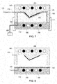
- Fig. 7 shows a pressurized state of the elastic layer 120 after the application of fluid 165 against it second surface.
- the application of fluid against the second surface 122 of the elastic layer 120 results in application of pressure of against the second surface of the 122 of the elastic layer 120, thereby expanding the elastic layer 120 to form an expanded elastic layer 125, as indicated in Fig. 7 .
- the expanded elastic layer 125 lifts away from the first surface 111 of the rigid support 110.
- the fluid 165 applies a pressure against the second surface 122 of the elastic layer 120 such that the elastic layer 120 is expanded against the inner surface 141 of the mold 140, as indicated in Fig. 7 .
- the fluid 165 fills the molding chamber 150, as indicated in Fig. 7 .
- the application of fluid 165 against the second surface 122 of the elastic layer 120 further results in pushing the prepreg 200 against the molding surface 142 of the mold 140, as indicated in Fig. 7 .
- the prepreg 200 is molded or formed into a shape in accordance with a profile of the molding surface 142 of the mold 140.
- the method includes forming a molded composite article 250, as indicated in Fig. 7 .
- the fluid 165 includes an inert gas, a liquid, or combinations thereof. In some embodiments, the fluid 165 includes water. In some embodiments, the fluid 165 includes air. In some embodiments, the fluid 165 includes an inert gas, such as, for example argon.
- the step 12 of applying a fluid further includes applying a positive pressure to the fluid 165.
- the fluid 165 may be pressurized using a suitable pressurization system at the desired pressure level before the application of fluid 165 against the second surface 122 of the elastic layer 120.
- a pressure of the fluid 165 applied to the second surface 122 of the elastic layer 120 is greater than about 1 bar.
- a pressure of the fluid 165 applied to the second surface 122 of the elastic layer 120 is greater than about 2 bar.
- a pressure of the fluid 165 applied to the second surface 122 of the elastic layer 120 is greater than about 5 bar.
- the at least one fluid port 160 is configured to provide the fluid 165 against the second surface 122 of the elastic layer 120 at a pressure greater than about 1 bar. It should be noted that the fluid port 165 configuration in Fig. 7 is shown as an exemplary embodiment only. In some embodiments, a plurality of fluid ports 165 may be employed to provide the fluid 165 against the second surface 122 of the elastic layer 120.
- the method 10 may further include a step of applying a vacuum 175 to the molding chamber 150.
- the vacuum may be applied prior to step 12, during step 12, or after step 12.
- the mold 140 may further include one or more vacuum ports 170 and a vacuum 175 may be applied to the molding chamber 150 using one or more of these ports 170, as indicated in Fig. 7 .
- application of vacuum 175 to the molding chamber 150 further pulls the first surface 121 of the elastic layer 120 towards the inner surface 142 of the mold 140.
- the method 10 includes a combination of application of pressurized fluid 165 against the elastic layer 120 and application of vacuum 175 to the molding chamber 150.
- the method 10 may further include heating one or more of the rigid support 110, the mold 140, or the fluid 165 during step 12 of applying the fluid 165 against the second surface 121 of the elastic layer 120. In some embodiments, heating the support 110, the mold 140, or the fluid 165 may provide for improved molding of the molded composite article 250. In some embodiments, the temperature of the support 110, the mold 140, or the fluid 165 may be maintained such that the curing of the prepreg 200 is not effected during the molding step 12.
- the method 10 further includes curing the molded composite article 250 in the molding chamber 150 to form a cured composite article 300.
- the methods and apparatus of the present invention advantageously allow for continuous molding and curing of composites without the need for transferring the molded composite article 250 to a separate curing system and use of autoclaves.
- the curing of the molding composite article 250 may be effected by heating one or more of the rigid support 110, the mold 140, or the fluid 165.
- the rigid support 110, the mold 140, or both may include one or more heating elements 180.
- the one or more heating elements 180 may be configured to directly effect curing of the molded composite article 250.
- the heating elements 180 may be used for heating the mold 140 and the molding surface 142 of the mold 140 such that curing of the molded composite article 250 is effected.
- the one or more heating elements 180 present in the rigid support 110 may be configured to provide heating to the fluid 165 disposed in the molding chamber 140 and the heated fluid 165 may provide heat to the molded composite article 250 to effect curing.
- the method 10 includes heating the fluid 165 to a cure temperature to effect curing of the molded composite article 250.
- the fluid 165 may be heated to a first temperature before the step 12 of applying the fluid 165 against the second surface 122 of the elastic layer 120. In such embodiments, the first temperature may be lower than the cure temperature. In some the embodiments, the fluid 165 may be further heated to a second temperature during the step 13 of curing the molded composite article 250. In such embodiments, the second temperature may be determined by the cure temperature of the molded composite article 250.
- the method 10 may include heating the fluid to the cure temperature and leaving the molding apparatus 100 in the pressurized state for a time period until the desired curing is achieved. In some embodiments, after the step 13 of curing the molded composite article, the molding apparatus 100 may be further cooled. In some embodiments, the method 10 further includes cooling one or more of the rigid support 110, the mold 140, or the fluid 165. As noted earlier, in some embodiments, the rigid support 110, the mold 140, or both may include one or more cooling elements 190. In some embodiments, the one or more cooling elements 190 may be configured to cool the fluid 165, the cured composite article 300, or both.
- the method 10 may further include discharging the fluid 165 from the molding chamber 150 using a suitable outlet (not shown) and releasing the pressure on the elastic layer 120.
- the elastic layer 120 may return to its original relaxed state and the cured composite article 300 may be removed from the molding apparatus 100, as indicated in Fig. 8 .
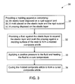
- a method 30 of manufacturing a cured composite article includes, at step 31, providing a molding apparatus 100.
- the molding apparatus 100 includes an elastic layer 120 disposed on a rigid support 110.
- the molding apparatus 100 further includes a mold 140 disposed on the elastic layer 120 and the support 110, wherein the mold 140 comprises an inner surface 141, the inner surface 141 further comprising a molding surface 142.
- a first surface 121 of the elastic layer 120 and the inner surface 141 of the mold 140 define a molding chamber 150.
- a prepreg 200 is further disposed within the molding chamber 150.
- the prepreg 200 is disposed on the first surface 121 of the elastic layer 120.
- the method 30 includes, at step 31, providing a fluid 165 via a fluid inlet 160 against a second surface 122 of the elastic layer 120.
- the method 30 includes expanding the elastic layer 120 against the inner surface 141 of the mold 140, as indicated in Fig. 7 .
- the method 30 further includes pushing the prepreg 200 against the molding surface 142 of the mold 141 to form a molded composite article 250, as indicated in Fig. 7 .
- the method further includes, at step 33, applying a positive pressure to the fluid 165 and heating the fluid 165 to a cure temperature. In one embodiment, as indicated in Fig. 3 , the method further includes, at step 34, curing the molded composite article 250 in the molding chamber 150 to form a cured composite article 300.
- an apparatus 100 for manufacturing a cured composite article 300 is provided.
- the apparatus 100 includes an elastic layer 120 disposed on a rigid support 100 and a mold 140 disposed on the elastic layer 120 and the rigid support 100.
- the mold 140 includes an inner surface 141.
- the inner surface 141 further includes a molding surface 142, as indicated in Fig. 4 .
- a first surface 121 of the elastic layer 120 and the inner surface 141 of the mold 140 defines a molding chamber 150.
- the molding chamber 150 is configured to receive a prepreg 200 disposed on the first surface 121 of the elastic layer 120, as indicated in Figures 4 and 6 .
- the apparatus 100 further includes at least one fluid port 160.
- the rigid support 110 includes the fluid port 160.
- the at least one fluid port 160 is configured to provide a fluid 165 against a second surface 122 of the elastic layer 120, as indicated in Figures 4 and 7 .
- the fluid port 160 is configured to provide a fluid 165, thereby expanding the elastic layer 120 against the inner surface 141 of the mold 140, and pushing the prepreg 200 against the molding surface 142 of the mold 140 to form a molded composite article 250.
- the at least one fluid port 160 is configured to provide the fluid 165 against the second surface 122 of the elastic layer 120 at a pressure greater than about 1 bar.
- the apparatus 100 further includes a fluid chamber 161 configured to provide the fluid 165 against the second surface 122 of the elastic layer 120 via the fluid port 160.
- the apparatus 100 further includes at least one vacuum port 170 configured to apply a 175 vacuum to the molding chamber 150, thereby pulling the first surface 121 of the elastic layer 120 towards the inner surface 141 of the mold 140.
- the apparatus 100 further includes at least one heating element 180 configured to cure the molded composite article 250, and form the cured composite article 300, as indicated in Figures 7 and 8 .
- the one or more heating elements are configured to heat one or more of the rigid support 110, the mold 140, or the fluid 165.
- the apparatus 100 further includes at least one cooling element 190, as indicated in Figures 7 and 8 .
- the one or more cooling elements 190 are configured to cool one or more of the rigid support 110, the mold 140, or the fluid 165.
- the methods and apparatus of the present invention may be advantageously suitable for making large composite components.
- a large composite component is one that has an overall dimension (length+width+thickness) greater than one foot.
- the methods and apparatus of the present invention may be used to form a cured composite article 300 selected from the group consisting of wind turbine components, aircraft components, and marine structures.
Landscapes
- Chemical & Material Sciences (AREA)
- Engineering & Computer Science (AREA)
- Composite Materials (AREA)
- Mechanical Engineering (AREA)
- Casting Or Compression Moulding Of Plastics Or The Like (AREA)
- Moulding By Coating Moulds (AREA)
Applications Claiming Priority (1)
| Application Number | Priority Date | Filing Date | Title |
|---|---|---|---|
| US13/217,586 US8591796B2 (en) | 2011-08-25 | 2011-08-25 | Methods and apparatus for molding and curing of composites |
Publications (3)
| Publication Number | Publication Date |
|---|---|
| EP2561978A2 true EP2561978A2 (de) | 2013-02-27 |
| EP2561978A3 EP2561978A3 (de) | 2017-11-22 |
| EP2561978B1 EP2561978B1 (de) | 2025-10-08 |
Family
ID=46940222
Family Applications (1)
| Application Number | Title | Priority Date | Filing Date |
|---|---|---|---|
| EP12180610.3A Active EP2561978B1 (de) | 2011-08-25 | 2012-08-16 | Verfahren und vorrichtung zum formpressen und härten von verbundstoffen |
Country Status (5)
| Country | Link |
|---|---|
| US (1) | US8591796B2 (de) |
| EP (1) | EP2561978B1 (de) |
| CN (1) | CN102950778B (de) |
| DK (1) | DK2561978T3 (de) |
| ES (1) | ES3056121T3 (de) |
Cited By (7)
| Publication number | Priority date | Publication date | Assignee | Title |
|---|---|---|---|---|
| WO2017067934A1 (de) * | 2015-10-20 | 2017-04-27 | Siempelkamp Maschinen- Und Anlagenbau Gmbh | Verfahren zum herstellen eines bauteils aus einem faserverbundwerkstoff |
| WO2017204920A1 (en) * | 2016-05-24 | 2017-11-30 | General Electric Company | Methods and systems including pressurized housings for forming materials |
| US10780614B2 (en) | 2016-05-24 | 2020-09-22 | General Electric Company | System and method for forming stacked materials |
| EP3812139A1 (de) * | 2019-10-24 | 2021-04-28 | Arrival Limited | Herstellung von verbundteilen |
| WO2021079116A1 (en) * | 2019-10-24 | 2021-04-29 | Arrival Limited | Composite panels and parts |
| US11648738B2 (en) | 2018-10-15 | 2023-05-16 | General Electric Company | Systems and methods of automated film removal |
| US11691356B2 (en) | 2021-02-08 | 2023-07-04 | General Electric Company | System and method for forming stacked materials |
Families Citing this family (5)
| Publication number | Priority date | Publication date | Assignee | Title |
|---|---|---|---|---|
| US9636876B2 (en) * | 2014-10-29 | 2017-05-02 | The Boeing Company | Method, device and apparatus for vacuum forming composite laminates |
| US10300634B2 (en) * | 2015-11-16 | 2019-05-28 | The Boeing Company | Advanced multiple grid heat sources to achieve optimized cure structure and method of making the same |
| CN108519022B (zh) * | 2017-12-29 | 2020-08-04 | 上海衡益特陶新材料有限公司 | 复合防弹件制造方法、复合防弹件和防弹制品 |
| CN108151586A (zh) * | 2017-12-29 | 2018-06-12 | 上海衡益特陶新材料有限公司 | 流体热压传导装置及其在制造复合防弹件中的应用和设备 |
| CN112172192B (zh) * | 2019-07-04 | 2022-05-27 | 中国航发商用航空发动机有限责任公司 | 预压实装置及预压实方法 |
Family Cites Families (14)
| Publication number | Priority date | Publication date | Assignee | Title |
|---|---|---|---|---|
| US4399100A (en) | 1980-12-29 | 1983-08-16 | Lockheed Corporation | Automatic process control system and method for curing polymeric materials |
| US5032525A (en) | 1988-03-31 | 1991-07-16 | United States Of America As Represented By The Secretary Of The Air Force | Qualitative process automation for autoclave cure of composite parts |
| US5530227A (en) * | 1991-04-05 | 1996-06-25 | The Boeing Company | Method and apparatus for consolidating organic matrix composites using induction heating |
| US5219498A (en) | 1991-11-12 | 1993-06-15 | Keller L Brian | Process for controlling curing and thermoforming of resins and composites |
| SE509503C2 (sv) * | 1997-05-12 | 1999-02-01 | Volvo Ab | Arrangemang, förfarande och hålkropp vid formning av plastdetaljer |
| US6290895B1 (en) * | 1997-10-14 | 2001-09-18 | General Electric Company | Selectively flexible caul and method of use |
| TW564219B (en) | 2001-01-25 | 2003-12-01 | Quickstep Technologies Pty Ltd | System and method for producing composite or bonded metal components |
| NZ565042A (en) | 2005-07-05 | 2009-10-30 | Quickstep Technologies Pty Ltd | Composite component production using fluid density and pressure |
| US8034278B2 (en) * | 2006-01-13 | 2011-10-11 | Hexcel Corporation | Pressurized molding of composite parts |
| ITMI20071308A1 (it) * | 2007-06-29 | 2008-12-30 | Mako Shark Srl | Attrezzatura per la realizzazione in pressa di pezzi in materiale composito |
| US8834782B2 (en) * | 2007-08-07 | 2014-09-16 | William L. Rodman | Composite structures and methods of making same |
| WO2010019697A1 (en) * | 2008-08-12 | 2010-02-18 | Armorsource Llc | Mold system and method for making helmet |
| CA2801886C (en) * | 2010-06-08 | 2018-04-24 | Stephen Paul Makin | Method of making automotive body parts |
| US9421717B2 (en) * | 2010-10-08 | 2016-08-23 | Gosakan Aravamudan | Manufacturing a composite |
-
2011
- 2011-08-25 US US13/217,586 patent/US8591796B2/en active Active
-
2012
- 2012-08-16 ES ES12180610T patent/ES3056121T3/es active Active
- 2012-08-16 DK DK12180610.3T patent/DK2561978T3/da active
- 2012-08-16 EP EP12180610.3A patent/EP2561978B1/de active Active
- 2012-08-24 CN CN201210306820.4A patent/CN102950778B/zh active Active
Non-Patent Citations (1)
| Title |
|---|
| None |
Cited By (9)
| Publication number | Priority date | Publication date | Assignee | Title |
|---|---|---|---|---|
| WO2017067934A1 (de) * | 2015-10-20 | 2017-04-27 | Siempelkamp Maschinen- Und Anlagenbau Gmbh | Verfahren zum herstellen eines bauteils aus einem faserverbundwerkstoff |
| JP2018531168A (ja) * | 2015-10-20 | 2018-10-25 | ジームペルカンプ・マシーネン−ウント−アンラーゲンバウ・ゲゼルシャフト・ミト・ベシュレンクテル・ハフツング | 繊維複合材料から成る部品を製造するための方法 |
| WO2017204920A1 (en) * | 2016-05-24 | 2017-11-30 | General Electric Company | Methods and systems including pressurized housings for forming materials |
| US10611097B2 (en) | 2016-05-24 | 2020-04-07 | General Electric Company | Methods and systems including pressurized housings for forming materials |
| US10780614B2 (en) | 2016-05-24 | 2020-09-22 | General Electric Company | System and method for forming stacked materials |
| US11648738B2 (en) | 2018-10-15 | 2023-05-16 | General Electric Company | Systems and methods of automated film removal |
| EP3812139A1 (de) * | 2019-10-24 | 2021-04-28 | Arrival Limited | Herstellung von verbundteilen |
| WO2021079116A1 (en) * | 2019-10-24 | 2021-04-29 | Arrival Limited | Composite panels and parts |
| US11691356B2 (en) | 2021-02-08 | 2023-07-04 | General Electric Company | System and method for forming stacked materials |
Also Published As
| Publication number | Publication date |
|---|---|
| CN102950778A (zh) | 2013-03-06 |
| EP2561978B1 (de) | 2025-10-08 |
| EP2561978A3 (de) | 2017-11-22 |
| ES3056121T3 (en) | 2026-02-18 |
| US20130049266A1 (en) | 2013-02-28 |
| DK2561978T3 (da) | 2025-11-17 |
| CN102950778B (zh) | 2017-04-05 |
| US8591796B2 (en) | 2013-11-26 |
Similar Documents
| Publication | Publication Date | Title |
|---|---|---|
| US8591796B2 (en) | Methods and apparatus for molding and curing of composites | |
| US10999052B1 (en) | Cauls and methods of using cauls to produce composite articles | |
| EP1808282B1 (de) | Formpressen von Verbundbauteilen | |
| KR100902962B1 (ko) | 구조용 부재를 형성하는 방법 및 장치 | |
| JP5533743B2 (ja) | 繊維強化プラスチックの製造方法 | |
| JP4515526B2 (ja) | 樹脂トランスファー成形法 | |
| US20120175824A1 (en) | Method of and Apparatus for Making a Composite Material | |
| US20160297153A1 (en) | Method for impregnation of a fibrous preform and device for implementation of the said method | |
| US9481136B2 (en) | Over-molded vacuum barrier and inner mold line bag carrier with soluble details in trapped closed mold tooling | |
| CN105283293A (zh) | 纤维增强塑料的制造方法及制造装置 | |
| US10052828B2 (en) | Supporting profiled element, method for producing a supporting profiled element, and use of said supporting profiled element in a method for producing a reinforced vehicle fuselage component | |
| JP2009542483A (ja) | 複合部品の製造方法 | |
| US12459170B2 (en) | Mold for manufacturing composite material molded product, and method for manufacturing composite material molded product | |
| KR20190049811A (ko) | 반자동 막-보조 압축 성형 공정 | |
| JP2008006814A (ja) | プリフォームの製造方法およびプリフォーム並びに繊維強化プラスチック桁材 | |
| JP6154670B2 (ja) | 繊維強化プラスチック部材の成形方法及び成形装置 | |
| JP5854430B2 (ja) | Frp製造装置およびfrp製造方法 | |
| US20220016812A1 (en) | Curing mold for manufacturing a turbomachine component made of composite material from a preform and method for manufacturing a component by means of such a mold | |
| JP2010274612A (ja) | Rtm成形法によるfrp成形品の製造方法とそのための金型 | |
| EP2871044A1 (de) | Verfahren zur Herstellung einer faserverstärkten Kunststoffkomponente und Formkern zur Verwendung in solch einem Verfahren | |
| JP2006159420A (ja) | Frp成形体の製造方法 | |
| Mitschang et al. | 1.8. 1■ General Objective |
Legal Events
| Date | Code | Title | Description |
|---|---|---|---|
| PUAI | Public reference made under article 153(3) epc to a published international application that has entered the european phase |
Free format text: ORIGINAL CODE: 0009012 |
|
| AK | Designated contracting states |
Kind code of ref document: A2 Designated state(s): AL AT BE BG CH CY CZ DE DK EE ES FI FR GB GR HR HU IE IS IT LI LT LU LV MC MK MT NL NO PL PT RO RS SE SI SK SM TR |
|
| AX | Request for extension of the european patent |
Extension state: BA ME |
|
| PUAL | Search report despatched |
Free format text: ORIGINAL CODE: 0009013 |
|
| AK | Designated contracting states |
Kind code of ref document: A3 Designated state(s): AL AT BE BG CH CY CZ DE DK EE ES FI FR GB GR HR HU IE IS IT LI LT LU LV MC MK MT NL NO PL PT RO RS SE SI SK SM TR |
|
| AX | Request for extension of the european patent |
Extension state: BA ME |
|
| RIC1 | Information provided on ipc code assigned before grant |
Ipc: B29C 70/44 20060101AFI20171013BHEP |
|
| STAA | Information on the status of an ep patent application or granted ep patent |
Free format text: STATUS: REQUEST FOR EXAMINATION WAS MADE |
|
| 17P | Request for examination filed |
Effective date: 20180522 |
|
| RBV | Designated contracting states (corrected) |
Designated state(s): AL AT BE BG CH CY CZ DE DK EE ES FI FR GB GR HR HU IE IS IT LI LT LU LV MC MK MT NL NO PL PT RO RS SE SI SK SM TR |
|
| STAA | Information on the status of an ep patent application or granted ep patent |
Free format text: STATUS: EXAMINATION IS IN PROGRESS |
|
| 17Q | First examination report despatched |
Effective date: 20200918 |
|
| P01 | Opt-out of the competence of the unified patent court (upc) registered |
Effective date: 20230522 |
|
| RAP1 | Party data changed (applicant data changed or rights of an application transferred) |
Owner name: LM WIND POWER A/S |
|
| RAP1 | Party data changed (applicant data changed or rights of an application transferred) |
Owner name: GENERAL ELECTRIC RENOVABLES ESPANA, S.L. |
|
| GRAP | Despatch of communication of intention to grant a patent |
Free format text: ORIGINAL CODE: EPIDOSNIGR1 |
|
| STAA | Information on the status of an ep patent application or granted ep patent |
Free format text: STATUS: GRANT OF PATENT IS INTENDED |
|
| INTG | Intention to grant announced |
Effective date: 20250716 |
|
| GRAS | Grant fee paid |
Free format text: ORIGINAL CODE: EPIDOSNIGR3 |
|
| GRAA | (expected) grant |
Free format text: ORIGINAL CODE: 0009210 |
|
| STAA | Information on the status of an ep patent application or granted ep patent |
Free format text: STATUS: THE PATENT HAS BEEN GRANTED |
|
| AK | Designated contracting states |
Kind code of ref document: B1 Designated state(s): AL AT BE BG CH CY CZ DE DK EE ES FI FR GB GR HR HU IE IS IT LI LT LU LV MC MK MT NL NO PL PT RO RS SE SI SK SM TR |
|
| REG | Reference to a national code |
Ref country code: GB Ref legal event code: FG4D Ref country code: CH Ref legal event code: F10 Free format text: ST27 STATUS EVENT CODE: U-0-0-F10-F00 (AS PROVIDED BY THE NATIONAL OFFICE) Effective date: 20251008 |
|
| REG | Reference to a national code |
Ref country code: DE Ref legal event code: R096 Ref document number: 602012081748 Country of ref document: DE |
|
| REG | Reference to a national code |
Ref country code: IE Ref legal event code: FG4D |
|
| REG | Reference to a national code |
Ref country code: DK Ref legal event code: T3 Effective date: 20251112 |
|
| REG | Reference to a national code |
Ref country code: NL Ref legal event code: MP Effective date: 20251008 |
|
| REG | Reference to a national code |
Ref country code: ES Ref legal event code: FG2A Ref document number: 3056121 Country of ref document: ES Kind code of ref document: T3 Effective date: 20260218 Ref country code: CH Ref legal event code: W10 Free format text: ST27 STATUS EVENT CODE: U-0-0-W10-W00 (AS PROVIDED BY THE NATIONAL OFFICE) Effective date: 20260218 |
|
| REG | Reference to a national code |
Ref country code: AT Ref legal event code: MK05 Ref document number: 1844504 Country of ref document: AT Kind code of ref document: T Effective date: 20251008 |
|
| PG25 | Lapsed in a contracting state [announced via postgrant information from national office to epo] |
Ref country code: NL Free format text: LAPSE BECAUSE OF FAILURE TO SUBMIT A TRANSLATION OF THE DESCRIPTION OR TO PAY THE FEE WITHIN THE PRESCRIBED TIME-LIMIT Effective date: 20251008 |
|
| RAP4 | Party data changed (patent owner data changed or rights of a patent transferred) |
Owner name: GE VERNOVA RENOVABLES ESPANA, S.L. |
|
| REG | Reference to a national code |
Ref country code: CH Ref legal event code: W10 Free format text: ST27 STATUS EVENT CODE: U-0-0-W10-W00 (AS PROVIDED BY THE NATIONAL OFFICE) Effective date: 20260325 |