EP1808282B1 - Formpressen von Verbundbauteilen - Google Patents
Formpressen von Verbundbauteilen Download PDFInfo
- Publication number
- EP1808282B1 EP1808282B1 EP07100316A EP07100316A EP1808282B1 EP 1808282 B1 EP1808282 B1 EP 1808282B1 EP 07100316 A EP07100316 A EP 07100316A EP 07100316 A EP07100316 A EP 07100316A EP 1808282 B1 EP1808282 B1 EP 1808282B1
- Authority
- EP
- European Patent Office
- Prior art keywords
- layer
- pressure
- composite body
- molding
- composite
- Prior art date
- Legal status (The legal status is an assumption and is not a legal conclusion. Google has not performed a legal analysis and makes no representation as to the accuracy of the status listed.)
- Not-in-force
Links
- 239000002131 composite material Substances 0.000 title claims abstract description 111
- 238000000465 moulding Methods 0.000 title claims abstract description 55
- 230000014759 maintenance of location Effects 0.000 claims abstract description 31
- 238000000034 method Methods 0.000 claims abstract description 24
- 238000010438 heat treatment Methods 0.000 claims description 7
- 238000003825 pressing Methods 0.000 claims description 3
- 239000000835 fiber Substances 0.000 description 31
- 229920005989 resin Polymers 0.000 description 29
- 239000011347 resin Substances 0.000 description 29
- 239000000463 material Substances 0.000 description 16
- 239000004744 fabric Substances 0.000 description 10
- 239000012530 fluid Substances 0.000 description 8
- 238000001802 infusion Methods 0.000 description 8
- 239000002952 polymeric resin Substances 0.000 description 6
- 229920003002 synthetic resin Polymers 0.000 description 6
- 239000013013 elastic material Substances 0.000 description 5
- 238000012545 processing Methods 0.000 description 5
- 239000007787 solid Substances 0.000 description 5
- -1 such as Polymers 0.000 description 5
- 239000007788 liquid Substances 0.000 description 4
- OKTJSMMVPCPJKN-UHFFFAOYSA-N Carbon Chemical compound [C] OKTJSMMVPCPJKN-UHFFFAOYSA-N 0.000 description 3
- 230000009172 bursting Effects 0.000 description 3
- 239000003795 chemical substances by application Substances 0.000 description 3
- 229920001778 nylon Polymers 0.000 description 3
- 238000009755 vacuum infusion Methods 0.000 description 3
- 239000011800 void material Substances 0.000 description 3
- 229910000851 Alloy steel Inorganic materials 0.000 description 2
- 239000004677 Nylon Substances 0.000 description 2
- 239000004698 Polyethylene Substances 0.000 description 2
- 239000000654 additive Substances 0.000 description 2
- 238000009826 distribution Methods 0.000 description 2
- 229910002804 graphite Inorganic materials 0.000 description 2
- 239000010439 graphite Substances 0.000 description 2
- 239000013529 heat transfer fluid Substances 0.000 description 2
- 239000011159 matrix material Substances 0.000 description 2
- 229920000573 polyethylene Polymers 0.000 description 2
- 229920005594 polymer fiber Polymers 0.000 description 2
- 229920000742 Cotton Polymers 0.000 description 1
- 229910001374 Invar Inorganic materials 0.000 description 1
- 229920000459 Nitrile rubber Polymers 0.000 description 1
- 239000004743 Polypropylene Substances 0.000 description 1
- 230000006978 adaptation Effects 0.000 description 1
- 238000013459 approach Methods 0.000 description 1
- 239000004760 aramid Substances 0.000 description 1
- 229920006231 aramid fiber Polymers 0.000 description 1
- 125000000484 butyl group Chemical group [H]C([*])([H])C([H])([H])C([H])([H])C([H])([H])[H] 0.000 description 1
- 229920005549 butyl rubber Polymers 0.000 description 1
- 229910052799 carbon Inorganic materials 0.000 description 1
- 239000000919 ceramic Substances 0.000 description 1
- 238000007596 consolidation process Methods 0.000 description 1
- 230000007423 decrease Effects 0.000 description 1
- 230000032798 delamination Effects 0.000 description 1
- 238000013461 design Methods 0.000 description 1
- 230000003467 diminishing effect Effects 0.000 description 1
- 230000000694 effects Effects 0.000 description 1
- 229920001971 elastomer Polymers 0.000 description 1
- 239000011521 glass Substances 0.000 description 1
- 239000003365 glass fiber Substances 0.000 description 1
- 239000003292 glue Substances 0.000 description 1
- 230000005484 gravity Effects 0.000 description 1
- 238000011065 in-situ storage Methods 0.000 description 1
- 238000010348 incorporation Methods 0.000 description 1
- 230000008595 infiltration Effects 0.000 description 1
- 238000001764 infiltration Methods 0.000 description 1
- 230000002452 interceptive effect Effects 0.000 description 1
- 238000011835 investigation Methods 0.000 description 1
- 238000004519 manufacturing process Methods 0.000 description 1
- 239000000203 mixture Substances 0.000 description 1
- 238000012986 modification Methods 0.000 description 1
- 230000004048 modification Effects 0.000 description 1
- 229920001084 poly(chloroprene) Polymers 0.000 description 1
- 229920000728 polyester Polymers 0.000 description 1
- 229920001155 polypropylene Polymers 0.000 description 1
- 229920001296 polysiloxane Polymers 0.000 description 1
- 230000002028 premature Effects 0.000 description 1
- 239000005060 rubber Substances 0.000 description 1
- 238000007789 sealing Methods 0.000 description 1
- 229920002379 silicone rubber Polymers 0.000 description 1
- 239000004945 silicone rubber Substances 0.000 description 1
- 229920003048 styrene butadiene rubber Polymers 0.000 description 1
- 229920002554 vinyl polymer Polymers 0.000 description 1
Images

Classifications
-
- B—PERFORMING OPERATIONS; TRANSPORTING
- B29—WORKING OF PLASTICS; WORKING OF SUBSTANCES IN A PLASTIC STATE IN GENERAL
- B29C—SHAPING OR JOINING OF PLASTICS; SHAPING OF MATERIAL IN A PLASTIC STATE, NOT OTHERWISE PROVIDED FOR; AFTER-TREATMENT OF THE SHAPED PRODUCTS, e.g. REPAIRING
- B29C70/00—Shaping composites, i.e. plastics material comprising reinforcements, fillers or preformed parts, e.g. inserts
- B29C70/04—Shaping composites, i.e. plastics material comprising reinforcements, fillers or preformed parts, e.g. inserts comprising reinforcements only, e.g. self-reinforcing plastics
- B29C70/28—Shaping operations therefor
- B29C70/40—Shaping or impregnating by compression not applied
- B29C70/42—Shaping or impregnating by compression not applied for producing articles of definite length, i.e. discrete articles
- B29C70/44—Shaping or impregnating by compression not applied for producing articles of definite length, i.e. discrete articles using isostatic pressure, e.g. pressure difference-moulding, vacuum bag-moulding, autoclave-moulding or expanding rubber-moulding
-
- B—PERFORMING OPERATIONS; TRANSPORTING
- B29—WORKING OF PLASTICS; WORKING OF SUBSTANCES IN A PLASTIC STATE IN GENERAL
- B29C—SHAPING OR JOINING OF PLASTICS; SHAPING OF MATERIAL IN A PLASTIC STATE, NOT OTHERWISE PROVIDED FOR; AFTER-TREATMENT OF THE SHAPED PRODUCTS, e.g. REPAIRING
- B29C43/00—Compression moulding, i.e. applying external pressure to flow the moulding material; Apparatus therefor
- B29C43/02—Compression moulding, i.e. applying external pressure to flow the moulding material; Apparatus therefor of articles of definite length, i.e. discrete articles
- B29C43/10—Isostatic pressing, i.e. using non-rigid pressure-exerting members against rigid parts or dies
- B29C43/12—Isostatic pressing, i.e. using non-rigid pressure-exerting members against rigid parts or dies using bags surrounding the moulding material or using membranes contacting the moulding material
-
- B—PERFORMING OPERATIONS; TRANSPORTING
- B29—WORKING OF PLASTICS; WORKING OF SUBSTANCES IN A PLASTIC STATE IN GENERAL
- B29C—SHAPING OR JOINING OF PLASTICS; SHAPING OF MATERIAL IN A PLASTIC STATE, NOT OTHERWISE PROVIDED FOR; AFTER-TREATMENT OF THE SHAPED PRODUCTS, e.g. REPAIRING
- B29C43/00—Compression moulding, i.e. applying external pressure to flow the moulding material; Apparatus therefor
- B29C43/32—Component parts, details or accessories; Auxiliary operations
- B29C43/36—Moulds for making articles of definite length, i.e. discrete articles
- B29C43/3642—Bags, bleeder sheets or cauls for isostatic pressing
-
- B—PERFORMING OPERATIONS; TRANSPORTING
- B29—WORKING OF PLASTICS; WORKING OF SUBSTANCES IN A PLASTIC STATE IN GENERAL
- B29C—SHAPING OR JOINING OF PLASTICS; SHAPING OF MATERIAL IN A PLASTIC STATE, NOT OTHERWISE PROVIDED FOR; AFTER-TREATMENT OF THE SHAPED PRODUCTS, e.g. REPAIRING
- B29C70/00—Shaping composites, i.e. plastics material comprising reinforcements, fillers or preformed parts, e.g. inserts
- B29C70/04—Shaping composites, i.e. plastics material comprising reinforcements, fillers or preformed parts, e.g. inserts comprising reinforcements only, e.g. self-reinforcing plastics
- B29C70/28—Shaping operations therefor
- B29C70/54—Component parts, details or accessories; Auxiliary operations, e.g. feeding or storage of prepregs or SMC after impregnation or during ageing
- B29C70/544—Details of vacuum bags, e.g. materials or shape
-
- B—PERFORMING OPERATIONS; TRANSPORTING
- B29—WORKING OF PLASTICS; WORKING OF SUBSTANCES IN A PLASTIC STATE IN GENERAL
- B29C—SHAPING OR JOINING OF PLASTICS; SHAPING OF MATERIAL IN A PLASTIC STATE, NOT OTHERWISE PROVIDED FOR; AFTER-TREATMENT OF THE SHAPED PRODUCTS, e.g. REPAIRING
- B29C43/00—Compression moulding, i.e. applying external pressure to flow the moulding material; Apparatus therefor
- B29C43/32—Component parts, details or accessories; Auxiliary operations
- B29C43/36—Moulds for making articles of definite length, i.e. discrete articles
- B29C43/3642—Bags, bleeder sheets or cauls for isostatic pressing
- B29C2043/3649—Inflatable bladders using gas or fluid and related details
-
- Y—GENERAL TAGGING OF NEW TECHNOLOGICAL DEVELOPMENTS; GENERAL TAGGING OF CROSS-SECTIONAL TECHNOLOGIES SPANNING OVER SEVERAL SECTIONS OF THE IPC; TECHNICAL SUBJECTS COVERED BY FORMER USPC CROSS-REFERENCE ART COLLECTIONS [XRACs] AND DIGESTS
- Y10—TECHNICAL SUBJECTS COVERED BY FORMER USPC
- Y10S—TECHNICAL SUBJECTS COVERED BY FORMER USPC CROSS-REFERENCE ART COLLECTIONS [XRACs] AND DIGESTS
- Y10S264/00—Plastic and nonmetallic article shaping or treating: processes
- Y10S264/50—Use of fluid pressure in molding
-
- Y—GENERAL TAGGING OF NEW TECHNOLOGICAL DEVELOPMENTS; GENERAL TAGGING OF CROSS-SECTIONAL TECHNOLOGIES SPANNING OVER SEVERAL SECTIONS OF THE IPC; TECHNICAL SUBJECTS COVERED BY FORMER USPC CROSS-REFERENCE ART COLLECTIONS [XRACs] AND DIGESTS
- Y10—TECHNICAL SUBJECTS COVERED BY FORMER USPC
- Y10S—TECHNICAL SUBJECTS COVERED BY FORMER USPC CROSS-REFERENCE ART COLLECTIONS [XRACs] AND DIGESTS
- Y10S425/00—Plastic article or earthenware shaping or treating: apparatus
- Y10S425/019—Flexible fluid pressure
Definitions
- the present invention relates generally to systems and methods for molding composite parts. More particularly, the invention is directed to systems and methods that apply pressure to the composite structure during the molding step.
- Composite materials are used extensively in the aerospace and marine industries, the wind energy turbine industry and in other situations where high strength and relatively light weight are desired.
- Composites typically include fibers and polymer resin as the two principal elements.
- a wide range of fiber types has been used in composites. Glass, graphite, carbon and ceramic fiber are common.
- the fibers can be chopped, randomly oriented, unidirectional in orientation or woven into fabric.
- the fibers used in composite materials have diameters that range from extremely small to relatively large. Although it is possible to make composites using large diameter fibers, the more common practice is to take thousands of fibers having extremely small diameters and form them into individual bundles known as tows. These multi-fiber tows are much stronger and more flexible than single fibers having the same overall diameter.
- the tows can be woven into fabric in the same manner a conventional yarns. Alternatively, the tows are arranged in parallel to provide a unidirectional fiber orientation or they can be randomly oriented.
- the ways in which the polymer resin is infused or impregnated into the complex fiber structure and the ways in which the resulting resin/fiber structure is cured are important considerations in the molding of composite parts.
- prepreg prefabricated lay-up
- the prepreg is made under manufacturing conditions that allow the amount and distribution of resin matrix within the prepreg to be carefully controlled. Once formed, the prepreg may be applied to a mold or other support surface in the same manner as a conventional manual lay-up.
- prepregs are not used immediately after they are formed. Instead, they usually are stored for use at a later time.
- Another popular way to combine the polymer resin and fibers is to use a vacuum to infuse the polymer resin into the fiber structure. Such vacuum infusion methods typically use a vacuum bag to surround the fiber structure during resin infusion.
- a common practice is to heat the composite body while at the same time applying pressure to the body. This is typically accomplished using an autoclave.
- positive pressure during molding provides many benefits including: reducing voids in the final composite part, providing complete resin infiltration of thick fiber structures, diminishing resin rich areas that are more susceptible to delamination, allowing for the use of high fiber volume fractions, allowing for the use of high viscosity resins and generally improving mechanical properties.
- Vacuum only processing of prepreg lay-ups can produce better results in terms of resin content homogeneity and a higher fiber volume fraction.
- vacuum-only processing tends to produce large parts that have higher void content due to air entrapment between prepreg layers. Less than 2% void content in composite parts having 55% fiber volume is possible with vacuum bag-only processing.
- the large scale laminates made using vacuum-only processing still exhibit higher void content than structures made using an autoclave or other system that applies positive pressure, in addition to atmospheric pressure, during the curing step.
- U.S. Patent No. 6,435,242 Another example of a pressure application system is described in U.S. Patent No. 6,435,242 where a positive pressure is applied by a bladder system that is secured to the mold via a vacuum seal.
- Other examples of pressure application systems that utilize combinations of flexible bladders and rigid components include: U.S. Patent No. 5,820,894 ; U.S. Patent No. 6,537,483 ; U.S. Patent No. 6,746,737 ; U.S. Patent No. 6,692,681 ; U.S. Patent No. 6,666,651 ; U.S. Patent No. 6,596,121 ; U.S. Patent No. 6,319,346 ; and German Patent DE 10150659 .
- a closed-mold resin infusion process has also been developed where positive pressure is applied using a rigid closed mold that includes an internal flexible sheet on one surface (See “ Investigation of a Two-Stage Injector Process to Reduce The Effects of In-Plane Resin Flow", Larsen et. al., Montana State University, AIAA-2002-0026 ).
- an apparatus and method are provided for molding composite bodies into composite parts using pressure.
- the apparatus includes a lower inflexible mold that is combined with an elastic upper mold layer to form a molding chamber in which the composite body to be molded is placed.
- An elastic pressure layer is located above the upper mold layer. The perimeters of the two elastic layers are sealed together to provide an elastic bladder that functions as a pressure chamber.
- a flexible expansion control layer is used to limit the increase in surface area of the pressure layer during pressurization.
- a perimeter retention lock is provided to prevent the perimeters of the elastic and flexible layers from moving inward or away from the lower mold during application of pressure to the pressure chamber.
- the pressure chamber is pressurized during molding to force the upper mold layer against the composite body and lower mold.
- This application of pressure during molding provides the many benefits of pressurized molding mentioned previously.
- the flexible expansion control layer allows one to pressurize the bladder to relatively high levels without over expanding and bursting the bladder.
- the apparatus may be used in combination with vacuum resin infusion systems where the composite body is surrounded with a vacuum bag to provide for infusion of resin into the composite.
- the apparatus may be heated in a variety of ways during molding when the resin system being used requires curing at elevated temperatures.
- the apparatus and methods of the present invention are particularly well suited for use in making large composite parts and provide a relatively simple, efficient and inexpensive alternative to autoclaves and other conventional pressure molding apparatus that are not well suited for use in making such large parts.
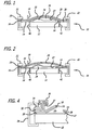
- FIG. 1 is a simplified cross-sectional representation of an apparatus in accordance with the present invention for molding a composite part where the apparatus is in a non-pressurized state.
- FIG. 2 is a simplified cross-sectional representation of the apparatus shown in Fig. 1 where the apparatus is in a pressurized state.
- FIG. 3 is a perspective view of an exemplary disassembled apparatus in accordance with the present invention.
- FIG. 4 is a sectional view of a portion of an apparatus in accordance with the present invention that shows an exemplary perimeter retention lock system.
- a disassembled preferred exemplary apparatus for molding a composite body into a composite part is shown, generally at 10 in FIG. 3 .
- the apparatus 10 includes an inflexible lower mold 12, elastic upper mold layer 14, elastic pressure layer 16, pressurization port 18, flexible expansion control layer 20 and a perimeter retention lock system shown generally at 22.
- the apparatus is designed to apply pressure to a composite body (uncured) to form or mold a composite part (cured).
- An exemplary composite body is shown at 24.
- the composite body 24 is made up of a combination of resin and fibers, as is well known.
- the apparatus 10 may be used to mold any of the resin/fiber combinations that are typically used in making composite parts.
- the apparatus may be used as a substitute for an autoclave or any of the other convention molding systems used for pressurized molding of composite materials.
- the apparatus 10 may be used to mold any size composite body. However, it is particularly well suited for use in making large composite parts from large composite bodies.
- a large composite body is one that has an overall dimension (length + width + thickness) of at least a few thirties of centimeters (feet). More typically, the overall dimension of a large composite body will range from three hundreds of centimeters (tens of feet) up to three thousands of centimeters (hundreds feet).
- Large composite parts are used widely in the aerospace, marine and wind energy turbine industries.
- An exemplary wind energy turbine blade skin has dimensions of 40 to 60 meters in length, 3 to 10 meters in width and thicknesses ranging from 2 to 30 mm.
- a typical large marine part is a boat or ship hull, which can have overall dimensions ranging from three hundreds of centiments (tens of feet) up to three thousands of centimeters (hundreds feet).
- Aerospace applications include a wide variety of structural or non-structural parts that can have overall dimensions ranging from a few thirties of centimeters (feet) up to three thousands of centimeters (hundreds of feet).
- large aerospace parts include wing skins, fuselage sections, fuselage frame sections and nose cones.
- the apparatus 10 is particularly well suited for molding relatively thick composite bodies having thicknesses that range from 12.7 mm (0.5 inch) to 76.2 mm (3 inches) and may have from a few to hundreds of plies.
- the lower mold 12 is preferably made from an inflexible material such as any of the steel alloys typically used to make autoclaves and pressurized molds. Invar 36 is an example.
- the lower mold may be made from other materials, such as composite materials, provided that the material is sufficiently rigid to withstand the single sided pressurization force exerted by the tool. See U.S. Patent No. 4,851,280 for examples of suitable composite materials that have been used as an alternative to steel alloys.
- the lower mold 12 includes an inflexible mold surface 26 on which the composite body 24. is placed for molding.
- the lower mold surface 26 may be machined or otherwise shaped to provide a molding contour.
- the mold surface 26 is shown as being flat in FIG. 3 for simplicity.
- the dimensions (width and length) of the mold 26 are chosen to match the particular part being made. As mentioned above, it is preferred that the apparatus be used to mold large parts. Accordingly, the mold surface 26 can be quite large and range from a few 0.09 cm 2 (square feet) to hundreds of 0.09 cm 2 (square feet).
- the mold 12 may be of any design and material used with typical permanent vacuum bags. Due to the application of high positive pressure, the mold underside should be reinforced. The mold can have a concave or convex profile for lay-up or resin infusion.
- the mold 12 also includes ports 40 and 42 that may be used as vacuum ports, ports for thermocouples and other sensor leads as well as resin infusion or for circulation of heating fluids or as ports for heating devices. The ports are located in the mold 12 to keep them from interfering with the elastic layers 14 and 16, flexible layer 20 and the perimeter retention lock system 22
- the elastic upper mold layer 14 has a mold surface 27 that covers the lower mold surface 26 to provide a molding cavity 28 in which the composite body 24 is located during molding of the composite body 24 into a composite part.
- the molding cavity 28 is shown in FIGS. 1 and 4 .
- the elastic upper mold layer is made from a strong, elastic material that is impermeable to gas and/or fluid. Exemplary materials include: rubbers, such as, silicone, neoprene, SBR, butyl and nitrile rubbers; and flexible bagging materials, such as, nylon, polypropylene, polyethylene and polyvinyl.
- the elastic material should preferably be capable of stretching from 100% to 600 % of its original size before failing.
- the width and length of the elastic upper mold layer 14 in a relaxed state is chosen to match the underlying lower mold 12.
- the thickness of the elastic upper mold layer 14 is varied depending upon the particular elastic material used and the expected pressure levels in the apparatus. Pressure levels on the order of just above atmospheric to 100 psi and more are possible. Pressures on the order of 206781 Pa (30 psi) to 413562 Pa (60 psi) are typically used. In general, the upper mold layer 14 will be from 0.005 mm (0.002 inch) to 0.635 mm (0.25 inch) thick.
- Preferred elastic materials include silicone rubber and high stretch nylon vacuum bag materials.
- the two layers 14 and 16 may be made from different materials, but are preferably made from material having the same composition and both layers preferably have the same relaxed dimensions.
- the perimeters of the two layers at the retention frame 32 must match, so that they can be sealed together to provide a bladder that forms pressure chamber 30, as shown in FIGS. 1, 2 and 4 .
- the term ""perimeter” is used in connection with the two layers 14 and 16, as well as the expansion control layer 20, it is intended to mean the perimeter of the layers as defined by retention frame 32 where the layers are clamped together and not the actual outer edges of the layers themselves.
- the pressurization port 18 is securely bounded or otherwise attached to pressure layer 16 to provide a route for pressurization of the chamber 30 with gas or liquid fluid.
- the flexible expansion control layer 20 is made from materials that are flexible, but relatively non-elastic.
- the material may or may not be impermeable to gas or liquid fluid.
- the material must be sufficiently strong to prevent the elastic pressure layer 16 from continuing to expand (i.e. increase in surface area) and bursting as pressure is increased in the pressure chamber 30.
- the material must be able to retain its strength at elevated molding temperatures if the apparatus is to be heated during the molding operation.
- Exemplary materials include cotton canvas, denim, fabrics made from nylon fibers, glass fibers, aramid fibers, polyethylene fibers, polyester fibers, graphite fibers and combinations thereof.
- the width and length of the flexible fabric layer 20 are chosen to match the underlying elastic upper mold layer 14, elastic pressure layer 16 and mold 12 at the perimeter as defined by the retention frame 32.
- the thickness is varied depending upon the fabric type used and the expected maximum operating pressure for the apparatus.
- a reinforced opening is provided in the fabric to allow the pressurization port 18 to pass through.
- the opening can be reinforced with the same fabric as the rest of the expansion control layer 20 or it can be reinforced using a heavier fabric or fibers or a solid sheet attached to the fabric around the opening. It is only important that the opening be reinforced sufficiently to prevent premature failure of the expansion control layer at the opening.
- the expansion control layer 20 may be made from solid films or sheets provided that they provide the required expansion control when the apparatus is pressurized. Solid films may not be as easy to shape into desired contours for certain applications. Accordingly, the use of a fabric expansion control layer is preferred.
- the perimeter retention lock 22 is composed of various elements that are designed to lock the perimeters of the elastic mold layer 14, elastic pressure layer 16 and flexible expansion control layer 20 to the lower mold 12. Locking of these three layers to the lower mold 12 prevents their perimeters from moving inward or away from the lower mold surface 26 during pressurization of the apparatus.
- an exemplary perimeter retention lock 22 includes a retention frame 32, four retention rails 34, clamp 36 for locking the expansion control layer 20 to the frame 32 and clamp 38 for locking the retention frame 32 and layers 14, 16 and 20 to the lower mold 12. It should be noted that only one set of clamps 36 and 38 are shown in FIG. 3 for simplicity.
- clamps 36 and 38 are required to lock the other three sides of the retention frame 32 to the lower mold 12.
- the number of clamps will vary and depends upon the size of the retention frame 32 as well as the particular materials used and the expected pressurization level. Typically, four or more clamps 36 are used per side to secure the flexible expansion control layer 20 between the retention frame 32 and the retention rail 34. In general, the number of clamps 38 used to secure the retention frame 32 to the mold 12 will be less than the number of clamps 36 that are used to secure the expansion control layer 20.
- the outer edge of the expansion control layer 20 is located between the retention frame 32 and retention rail 34 and securely clamped in place using clamp 36.
- the clamp 36 may be clamped directly to the retention frame 32 or, as shown in FIG. 4 , the expansion control layer 20 may be overlapped and clamped between the clamp 36 and retention frame 32. It is preferred that the clamp 36 include a clamping surface 37 that has a surface area and shape which provides for secure clamping of the expansion control layer 20 to the retention frame 32 without damaging the layer.
- the outer edges of the expansion control layer 20, mold layer 14 and pressure layer 16 are located between the retention frame 32 and lower mold surface 26 and securely clamped in place using clamp 38 to form the perimeter of the mold.
- This particular perimeter retention lock configuration insures that the expansion control layer 20 is secured tightly to the retention frame 32 and that the two elastic layers 14 and 16 and the retention frame 32 are secured to the mold 12.
- This locking configuration prevents the perimeters of the three layers 14, 16 and 20 from moving inward or away from the lower mold surface 26 during application of pressure to the pressure chamber 30.
- the two elastic layers 14 and 16 be sealed together in a tight fashion around their perimeters to form the pressure chamber 30. Especially when using a liquid fluid, no leakage is preferred, but some leakage is acceptable for gas fluids so long as the pressure source can compensate for the leakage. If desired, the two elastic layers 14 and 16 can be sealed around their perimeters using heat and/or a suitable glue or other sealing agent. Alternatively, the pressure applied by clamp 38 may be sufficient to mechanically seal the layers together to form the pressure chamber 30. It is preferred that a combination of bonding and clamping pressure be used to seal the perimeters of the two elastic layers together while at the same time securing them to the lower mold 12 with clamps 38.
- FIG. 1 A simplified view of the molding apparatus 10 in a non-pressurized state is shown in FIG. 1 .
- a corresponding view of the molding apparatus 10 in a pressurized state is shown in FIG. 2 .
- These simplified views will be used to describe the operation and use of the molding apparatus 10 to mold a composite body 24 into a composite part.
- the composite body 24 can be located in a disposable vacuum bag (not shown) and subjected to vacuum infusion of resin in accordance with known resin infusion procedures.
- a vacuum may also be applied by incorporation of a vacuum tight seal between the lower mold surface 26 and the elastic upper mold layer 14, such as with a permanent or reusable vacuum bag.
- the seal of the bag must be entirely within or outside of the perimeter retention lock system 22, so as not to crush the vacuum bag seal.
- the composite body 24 is located in the molding cavity 28, which is formed between the lower mold 12 and the elastic upper mold 14.
- the elastic upper mold layer 14 and elastic pressure layer 16 are in a relaxed state so that the volume of the pressure chamber 30 is at a minimum.
- Pressure is applied to the apparatus by introducing pressurized gas or liquid fluid into the pressure chamber 30 through the pressurization port 18.
- the pressurization of chamber 30 increases the volume of chamber 30 and causes an increase in the surface area of the elastic pressure layer 16.
- the upper mold layer 14 is compressed down against the composite body 24.
- the flexible expansion' control layer 20 prevents the pressure layer 16 from over expanding and bursting.
- the amount of expansion allowed by the control layer 20 should be less than 80% of the expansion capability of the pressure layer 16 and preferably less than a 200% increase in surface area.
- the particular expansion limit will vary depending upon the specific elastic material being used and the amount of pressure applied to the pressure chamber 30.
- the material for the expansion control layer 20 is chosen to provide the desired limits on pressure layer expansion.
- the apparatus 10 is left in the pressurized state ( FIG. 2 ) for a sufficient time to allow the composite body 24 to be consolidated and cured into the composite part.
- the body may need to be heated during the consolidation and curing process. Heat may be applied using a flexible blanket placed on top of or under the composite body 24.
- heating rods can be incorporated into the mold 12 or a heating fluid can be circulated through the ports in the mold or through the pressure chamber 30. Heating devices may also be introduced through ports 40 and/or 42.
- the pressure is released from chamber 30 and the elastic and flexible layers are allowed to return to their relaxed state as shown in FIG. 1 . If heated, the apparatus is allowed to cool. The perimeter retention lock 22 is then disengaged and the composite part removed.
Landscapes
- Engineering & Computer Science (AREA)
- Mechanical Engineering (AREA)
- Chemical & Material Sciences (AREA)
- Composite Materials (AREA)
- Casting Or Compression Moulding Of Plastics Or The Like (AREA)
- Moulds For Moulding Plastics Or The Like (AREA)
- Compositions Of Macromolecular Compounds (AREA)
Claims (12)
- Vorrichtung (10) zum Formen eines Verbundkörpers (24) in ein Verbundbauteil, wobei die Vorrichtung umfaßt:eine untere Form (12), die eine unelastische Formoberfläche (26) umfaßt, auf welcher der Verbundkörper (24) aufgelegt ist,eine elastische, obere Formschicht (14), die eine Formoberfläche (27) umfaßt, die die untere Formoberfläche (26) abdeckt, um eine Formkavität (28) bereitzustellen, in welcher sich der Verbundkörper (24) während des Formens des Verbundkörpers (24) in das Verbundbauteil befindet, wobei die obere Formschicht (14) eine Umrahmung aufweist,eine elastische Druckschicht (16), die sich oberhalb der oberen Formschicht (14) befindet, wobei die Druckschicht (16) eine Umrahmung aufweist, die gegen die obere Formschicht (14) abgedichtet ist, um eine Druckkammer (30) bereitzustellen, die sich zwischen der oberen Formschicht (14) und der Druckschicht (16) befindet,einen Druckanschluß (18), um eine Beaufschlagung der Druckkammer (30) mit Druck zu ermöglichen, um das Volumen der Druckkammer (30) zu vergrößern, wobei die Volumenvergrößerung der Druckkammer (30) die Oberfläche der Druckschicht (16) vergrößert,eine flexible Dehnungskontrollschicht (20), die sich oberhalb der Druckschicht (16) befindet, um die Vergrößerung der Oberfläche der Druckschicht (16) zu begrenzen, undeine Umrahmungsverriegelung (22), die sich um die Umrahmungen der oberen Formschicht (14), der Druckschicht (16) und der Dehnungskontrollschicht (20) herum befindet, um die Umrahmungen an einer Verschiebung während der Druckbeaufschlagung der Druckkammer nach innen oder weg von der unteren Formoberfläche (26) zu hindern.
- Vorrichtung (10) zum Formen eines Verbundkörpers (24) in ein Verbundbauteil nach Anspruch 1, wobei die Vorrichtung (10) einen großen Verbundkörper (24) umfaßt, der eine Gesamtabmessung innerhalb der Formkavität (28) von mindestens dreihundert Zentimetern (zehn Fuß) aufweist.
- Vorrichtung (10) zum Formen eines Verbundkörpers (24) in ein Verbundbauteil nach Anspruch 2, wobei der große Verbundkörper (24) aus der Gruppe gewählt ist, die aus Windenergie-Turbinenschaufeln, Luftfahrtstrukturen und Schiffsbaustrukturen besteht.
- Vorrichtung (10) zum Formen eines Verbundkörpers (24) in ein Verbundbauteil nach Anspruch 1, wobei sich ein Verbundkörper (24) in der Formkavität (28) befindet und wobei ein Unterdruckbeutel den Verbundkörper umgibt.
- Vorrichtung (10) zum Formen eines Verbundkörpers (24) in ein Verbundbauteil nach Anspruch 2, wobei ein Unterdruckbeutel den großen Verbundkörper (24) umgibt.
- Vorrichtung (10) zum Formen eines Verbundkörpers in ein Verbundbauteil nach einem der Ansprüche 1 bis 5, wobei die Vorrichtung ein Heizelement umfaßt, um die Formkavität während des Formens des Verbundkörpers in das Verbundbauteil mit Wärme zu beaufschlagen.
- Verfahren zum Formen eines Verbundkörpers (24) in ein Verbundbauteil, die Schritte umfassend:A) Bereitstellen einer Vorrichtung (10), umfassend:eine untere Form (12), die eine unelastische Formoberfläche (26) umfaßt, auf welcher der Verbundkörper aufgelegt wird,eine elastische, obere Formschicht (14), die eine Formoberfläche (27) umfaßt, die die untere Formoberfläche (26) abdeckt, um eine Formkavität (28) bereitzustellen, in welcher sich der Verbundkörper (24) während der Formens des Verbundkörpers (24) in das Verbundbauteil befindet, wobei die obere Formschicht (14) eine Umrahmung aufweist,eine elastische Druckschicht (16), die sich oberhalb der oberen Formschicht (14) befindet, wobei die Druckschicht (16) eine Umrahmung aufweist, die gegen die obere Formschicht (14) abgedichtet ist, um eine Druckkammer (30) bereitzustellen, die sich zwischen der oberen Formschicht (14) und der Druckschicht (16) befindet,einen Druckanschluß (18), um die Beaufschlagung der Druckkammer (30) mit Druck zu ermöglichen, um das Volumen der Druckkammer (30) zu vergrößern, wobei die Volumenvergrößerung der Druckkammer (30) die Oberfläche der Druckschicht (16) vergrößert,eine flexible Dehnungskontrollschicht (20), die sich oberhalb der Druckschicht (16) befindet, um die Vergrößerung der Oberfläche der Druckschicht (16) zu begrenzen,eine Umrahmungsverriegelung (22), die sich um die Umrahmungen der oberen Formschicht (14), der Druckschicht (16) und der Dehnungskontrollschicht (20) herum befindet, um die Umrahmungen an einer Verschiebung während der Druckbeaufschlagung der Druckkammer (30) nach innen oder weg von der unteren Formoberfläche (26) zu hindern,B) Einbringen eines Verbundkörpers (24) in die Formkavität (28), undC) Beaufschlagen der Druckkammer (30) mit Druck über den Druckanschluß (18), um eine Vergrößerung des Volumens der Druckkammer (30) bereitzustellen.
- Verfahren zum Formen eines Verbundkörpers (24) in ein Verbundbauteil nach Anspruch 7, das den zusätzlichen Schritt des Erwärmens des in der Formkavität (28) befindlichen Verbundkörpers (24) umfaßt.
- Verfahren zum Formen eines Verbundkörpers (24) in ein Verbundbauteil nach Anspruch 7 oder 8, wobei der Verbundkörper (24) ein großer Verbundkörper ist, der eine Gesamtabmessung von mindestens dreihundert Zentimetern (zehn Fuß) aufweist.
- Verfahren zum Formen eines Verbundkörpers (24) in ein Verbundbauteil nach Anspruch 9, wobei der große Verbundkörper (24) aus einer Gruppe gewählt ist, die aus Windenergie-Turbinenschafeln, Luftfahrtstrukturen und Schiffsbaustrukturen besteht.
- Verfahren zum Formen eines Verbundkörpers (24) in ein Verbundbauteil nach einem der Ansprüche 7 bis 10, wobei ein Unterdruckbeutel den Verbundkörper (24) umgibt.
- Verfahren zum Formen eines Verbundkörpers in ein Verbundbauteil nach Anspruch 9, wobei ein Unterdruckbeutel den großen Verbundkörper umgibt.
Applications Claiming Priority (1)
| Application Number | Priority Date | Filing Date | Title |
|---|---|---|---|
| US11/331,511 US8034278B2 (en) | 2006-01-13 | 2006-01-13 | Pressurized molding of composite parts |
Publications (2)
| Publication Number | Publication Date |
|---|---|
| EP1808282A1 EP1808282A1 (de) | 2007-07-18 |
| EP1808282B1 true EP1808282B1 (de) | 2009-04-01 |
Family
ID=37847111
Family Applications (1)
| Application Number | Title | Priority Date | Filing Date |
|---|---|---|---|
| EP07100316A Not-in-force EP1808282B1 (de) | 2006-01-13 | 2007-01-10 | Formpressen von Verbundbauteilen |
Country Status (6)
| Country | Link |
|---|---|
| US (1) | US8034278B2 (de) |
| EP (1) | EP1808282B1 (de) |
| AT (1) | ATE427200T1 (de) |
| DE (1) | DE602007000784D1 (de) |
| DK (1) | DK1808282T3 (de) |
| ES (1) | ES2325185T3 (de) |
Cited By (2)
| Publication number | Priority date | Publication date | Assignee | Title |
|---|---|---|---|---|
| EP2471649A1 (de) | 2010-12-31 | 2012-07-04 | Fundacion Inasmet | Membranmanipulations- und Komprimiervorrichtung zur automatischen Herstellung von Verbundstoffvorformen, und Verfahren zum Erhalten der Vorformen |
| DE102015211671A1 (de) * | 2015-06-24 | 2016-12-29 | Airbus Operations Gmbh | Verfahren und Vorrichtung zur Herstellung eines Bauteils unter Verwendung einer Vakuumfolie |
Families Citing this family (13)
| Publication number | Priority date | Publication date | Assignee | Title |
|---|---|---|---|---|
| AU2008218935B8 (en) * | 2007-02-23 | 2012-07-26 | Richard W. Rydin | Method of making a natural rubber vacuum bag by spray processes, Natural rubber vacuum bag made using spray process, and method for using natural rubber bag made using spray process |
| US8672665B2 (en) | 2007-05-18 | 2014-03-18 | Arjr Group, Llc | Vacuum bag with integral fluid transfer conduits and seals for resin transfer and other processes |
| WO2009152109A1 (en) * | 2008-06-13 | 2009-12-17 | Incitor, Llc | Single strand dimensional construction of dna in 3d space |
| EP3276162B1 (de) | 2008-12-05 | 2020-04-08 | Vestas Wind Systems A/S | Effiziente windturbinenschaufeln, windturbinenschaufelstrukturen sowie zugehörige systeme und verfahren zur herstellung, montage und verwendung |
| US9500179B2 (en) | 2010-05-24 | 2016-11-22 | Vestas Wind Systems A/S | Segmented wind turbine blades with truss connection regions, and associated systems and methods |
| EP2511080B1 (de) | 2011-04-12 | 2018-07-11 | Fundacion Tecnalia Research & Innovation | Vorrichtung zur Herstellung von Vorformen von kohlenstofffaserverstärkten Komponenten |
| US8591796B2 (en) * | 2011-08-25 | 2013-11-26 | General Electric Company | Methods and apparatus for molding and curing of composites |
| US9470205B2 (en) | 2013-03-13 | 2016-10-18 | Vestas Wind Systems A/S | Wind turbine blades with layered, multi-component spars, and associated systems and methods |
| US11958217B2 (en) * | 2017-10-09 | 2024-04-16 | General Electric Company | Systems and methods for compacting composite components |
| KR102128948B1 (ko) * | 2018-06-15 | 2020-07-01 | 남경필 | 자동차 내장재의 원단 부착장치 |
| CN114905770B (zh) * | 2021-02-08 | 2024-03-22 | 中国航发商用航空发动机有限责任公司 | 叶片成型方法和模具 |
| CN113103470A (zh) * | 2021-03-31 | 2021-07-13 | 青岛博锐智远减振科技有限公司 | 橡胶硫化粘合性能测试试样制备模具及制样方法 |
| CN113997601B (zh) * | 2021-11-05 | 2024-03-08 | 中航沈飞民用飞机有限责任公司 | 一种v形复合材料零件的补偿加压方法 |
Family Cites Families (20)
| Publication number | Priority date | Publication date | Assignee | Title |
|---|---|---|---|---|
| FR1301825A (fr) | 1961-05-13 | 1962-08-24 | Zd Y V I | Procédé et dispositif de moulage par compression à l'aide de membranes et durcissement chimique de matériaux chimiquement durcissables |
| DE1629479A1 (de) | 1966-11-18 | 1971-01-28 | Inst Schienenfahrzeuge | Verfahren und Vorrichtung zur Herstellung eines stoss- und geraeuschdaempfenden Radkoerpers fuer schnellaufende Schienenfahrzeuge |
| US3661683A (en) * | 1970-11-03 | 1972-05-09 | Airline Systems Inc | Patch press |
| GB2065022A (en) * | 1979-12-08 | 1981-06-24 | British Aerospace | Apparatus and method for forming and curing |
| FR2673571B1 (fr) | 1991-03-07 | 1994-09-16 | Acb | Procede de fabrication d'un stratifie constitue de renforts fibreux impregnes de resine thermodurcissable. |
| US5430937A (en) * | 1994-07-15 | 1995-07-11 | United Technologies Corporation | Apparatus and methods for fabricating a helicopter main rotor blade |
| US5772950A (en) * | 1994-08-31 | 1998-06-30 | The Boeing Company | Method of vacuum forming a composite |
| US5820894A (en) * | 1995-10-06 | 1998-10-13 | Mcdonnell Douglas Corporation | Method and apparatus for consolidating a workpiece at elevated temperature |
| US6231796B1 (en) * | 1996-04-26 | 2001-05-15 | Edward H. Allen | Pulsed method for creating composite structures |
| US6692681B1 (en) * | 1997-01-29 | 2004-02-17 | Raytheon Aircraft Company | Method and apparatus for manufacturing composite structures |
| US6319346B1 (en) * | 1997-04-23 | 2001-11-20 | Radius Engineering, Inc. | Method for manufacture of composite aircraft control surfaces |
| US6435242B1 (en) * | 1998-03-23 | 2002-08-20 | Northrop Grumman Corp | Repair pressure applicator |
| US6537483B1 (en) * | 1999-02-05 | 2003-03-25 | The B. F. Goodrich Company | Pressure equalized vacuum resin infusion process |
| US6596121B1 (en) * | 1999-11-04 | 2003-07-22 | Hydril Company | Method of making composite liner for oilfield tubular goods |
| US6562436B2 (en) * | 2000-02-25 | 2003-05-13 | The Boeing Company | Laminated composite radius filler |
| FR2811933B1 (fr) * | 2000-07-20 | 2003-05-23 | Vetrotex France Sa | Corps creux composite et son procede de fabrication |
| DE10150659A1 (de) | 2001-10-17 | 2003-05-08 | Kraft Uwe | Vorrichtung zur Herstellung von Kunststoffbauteilen |
| US6666651B2 (en) * | 2002-02-20 | 2003-12-23 | Jim Rust | Composite propeller blade with unitary metal ferrule and method of manufacture |
| US7105122B2 (en) * | 2002-10-08 | 2006-09-12 | Ossur Hf | Prosthesis socket direct casting device having multiple compression chambers |
| US7326044B2 (en) * | 2003-05-05 | 2008-02-05 | Ortho-Active Holdings Inc. | Rapid thermoform pressure forming process and apparatus |
-
2006
- 2006-01-13 US US11/331,511 patent/US8034278B2/en not_active Expired - Fee Related
-
2007
- 2007-01-10 EP EP07100316A patent/EP1808282B1/de not_active Not-in-force
- 2007-01-10 DK DK07100316T patent/DK1808282T3/da active
- 2007-01-10 DE DE602007000784T patent/DE602007000784D1/de active Active
- 2007-01-10 ES ES07100316T patent/ES2325185T3/es active Active
- 2007-01-10 AT AT07100316T patent/ATE427200T1/de active
Cited By (2)
| Publication number | Priority date | Publication date | Assignee | Title |
|---|---|---|---|---|
| EP2471649A1 (de) | 2010-12-31 | 2012-07-04 | Fundacion Inasmet | Membranmanipulations- und Komprimiervorrichtung zur automatischen Herstellung von Verbundstoffvorformen, und Verfahren zum Erhalten der Vorformen |
| DE102015211671A1 (de) * | 2015-06-24 | 2016-12-29 | Airbus Operations Gmbh | Verfahren und Vorrichtung zur Herstellung eines Bauteils unter Verwendung einer Vakuumfolie |
Also Published As
| Publication number | Publication date |
|---|---|
| DE602007000784D1 (de) | 2009-05-14 |
| DK1808282T3 (da) | 2009-07-13 |
| EP1808282A1 (de) | 2007-07-18 |
| ES2325185T3 (es) | 2009-08-27 |
| ATE427200T1 (de) | 2009-04-15 |
| US8034278B2 (en) | 2011-10-11 |
| US20070164479A1 (en) | 2007-07-19 |
Similar Documents
| Publication | Publication Date | Title |
|---|---|---|
| EP1808282B1 (de) | Formpressen von Verbundbauteilen | |
| Williams et al. | Resin infusion under flexible tooling (RIFT): a review | |
| JP5670381B2 (ja) | 制御された大気圧樹脂注入プロセス | |
| US10999052B1 (en) | Cauls and methods of using cauls to produce composite articles | |
| US8591796B2 (en) | Methods and apparatus for molding and curing of composites | |
| KR101995529B1 (ko) | 섬유 강화 복합 몰딩 | |
| US8567467B2 (en) | Process and apparatus for producing composite structures | |
| CA2245088C (en) | Method for forming inner mold line tooling without a part model | |
| US20080210372A1 (en) | Composite article debulking process | |
| US20100310818A1 (en) | Method of moulding a charge | |
| WO2008086022A1 (en) | Multi-function vacuum bag for composite part manuacture | |
| JP4639549B2 (ja) | Frpの製造方法 | |
| US20130209601A1 (en) | Processes and systems for manufacturing spars and other hollow structures | |
| JP4805375B2 (ja) | Frp構造体の製造方法 | |
| US20040000745A1 (en) | Moulding of composite materials | |
| JP4839523B2 (ja) | 繊維強化樹脂の製造方法 | |
| EP3815888B1 (de) | Reparatursysteme und reparaturen für vakuumbeutellose verbundwerkstoffe | |
| EP4074498B1 (de) | Vorrichtung und verfahren zur verarbeitung einer verbundstruktur | |
| EP4491382B1 (de) | Härtungswerkzeuganordnungen, verfahren und systeme zur verbundherstellung | |
| Sahin et al. | Production processing of fabric reinforced composites by vacuum-assisted resin transfer molding | |
| JP2009045927A (ja) | 繊維強化プラスチックの製造方法 | |
| US20240140053A1 (en) | Double Vacuum Debulk Processing | |
| JP4645775B2 (ja) | Frpの製造方法 | |
| JPH04251715A (ja) | 炭素繊維強化複合材料の作製方法 | |
| JP2006159420A (ja) | Frp成形体の製造方法 |
Legal Events
| Date | Code | Title | Description |
|---|---|---|---|
| PUAI | Public reference made under article 153(3) epc to a published international application that has entered the european phase |
Free format text: ORIGINAL CODE: 0009012 |
|
| AK | Designated contracting states |
Kind code of ref document: A1 Designated state(s): AT BE BG CH CY CZ DE DK EE ES FI FR GB GR HU IE IS IT LI LT LU LV MC NL PL PT RO SE SI SK TR |
|
| AX | Request for extension of the european patent |
Extension state: AL BA HR MK YU |
|
| 17P | Request for examination filed |
Effective date: 20080109 |
|
| 17Q | First examination report despatched |
Effective date: 20080208 |
|
| AKX | Designation fees paid | ||
| RBV | Designated contracting states (corrected) |
Designated state(s): AT BE BG CH CY CZ DE DK EE ES FI FR GB GR HU IE IS IT LI LT LU LV MC NL PL PT RO SE SI SK TR |
|
| REG | Reference to a national code |
Ref country code: DE Ref legal event code: 8566 |
|
| GRAP | Despatch of communication of intention to grant a patent |
Free format text: ORIGINAL CODE: EPIDOSNIGR1 |
|
| GRAS | Grant fee paid |
Free format text: ORIGINAL CODE: EPIDOSNIGR3 |
|
| GRAA | (expected) grant |
Free format text: ORIGINAL CODE: 0009210 |
|
| AK | Designated contracting states |
Kind code of ref document: B1 Designated state(s): AT BE BG CH CY CZ DE DK EE ES FI FR GB GR HU IE IS IT LI LT LU LV MC NL PL PT RO SE SI SK TR |
|
| REG | Reference to a national code |
Ref country code: GB Ref legal event code: FG4D |
|
| REG | Reference to a national code |
Ref country code: CH Ref legal event code: EP |
|
| REG | Reference to a national code |
Ref country code: IE Ref legal event code: FG4D |
|
| REF | Corresponds to: |
Ref document number: 602007000784 Country of ref document: DE Date of ref document: 20090514 Kind code of ref document: P |
|
| REG | Reference to a national code |
Ref country code: DK Ref legal event code: T3 |
|
| PG25 | Lapsed in a contracting state [announced via postgrant information from national office to epo] |
Ref country code: SI Free format text: LAPSE BECAUSE OF FAILURE TO SUBMIT A TRANSLATION OF THE DESCRIPTION OR TO PAY THE FEE WITHIN THE PRESCRIBED TIME-LIMIT Effective date: 20090401 |
|
| REG | Reference to a national code |
Ref country code: ES Ref legal event code: FG2A Ref document number: 2325185 Country of ref document: ES Kind code of ref document: T3 |
|
| PG25 | Lapsed in a contracting state [announced via postgrant information from national office to epo] |
Ref country code: LT Free format text: LAPSE BECAUSE OF FAILURE TO SUBMIT A TRANSLATION OF THE DESCRIPTION OR TO PAY THE FEE WITHIN THE PRESCRIBED TIME-LIMIT Effective date: 20090401 Ref country code: PT Free format text: LAPSE BECAUSE OF FAILURE TO SUBMIT A TRANSLATION OF THE DESCRIPTION OR TO PAY THE FEE WITHIN THE PRESCRIBED TIME-LIMIT Effective date: 20090902 Ref country code: FI Free format text: LAPSE BECAUSE OF FAILURE TO SUBMIT A TRANSLATION OF THE DESCRIPTION OR TO PAY THE FEE WITHIN THE PRESCRIBED TIME-LIMIT Effective date: 20090401 Ref country code: EE Free format text: LAPSE BECAUSE OF FAILURE TO SUBMIT A TRANSLATION OF THE DESCRIPTION OR TO PAY THE FEE WITHIN THE PRESCRIBED TIME-LIMIT Effective date: 20090401 |
|
| PG25 | Lapsed in a contracting state [announced via postgrant information from national office to epo] |
Ref country code: LV Free format text: LAPSE BECAUSE OF FAILURE TO SUBMIT A TRANSLATION OF THE DESCRIPTION OR TO PAY THE FEE WITHIN THE PRESCRIBED TIME-LIMIT Effective date: 20090401 Ref country code: SE Free format text: LAPSE BECAUSE OF FAILURE TO SUBMIT A TRANSLATION OF THE DESCRIPTION OR TO PAY THE FEE WITHIN THE PRESCRIBED TIME-LIMIT Effective date: 20090701 Ref country code: PL Free format text: LAPSE BECAUSE OF FAILURE TO SUBMIT A TRANSLATION OF THE DESCRIPTION OR TO PAY THE FEE WITHIN THE PRESCRIBED TIME-LIMIT Effective date: 20090401 Ref country code: IS Free format text: LAPSE BECAUSE OF FAILURE TO SUBMIT A TRANSLATION OF THE DESCRIPTION OR TO PAY THE FEE WITHIN THE PRESCRIBED TIME-LIMIT Effective date: 20090801 |
|
| PG25 | Lapsed in a contracting state [announced via postgrant information from national office to epo] |
Ref country code: CZ Free format text: LAPSE BECAUSE OF FAILURE TO SUBMIT A TRANSLATION OF THE DESCRIPTION OR TO PAY THE FEE WITHIN THE PRESCRIBED TIME-LIMIT Effective date: 20090401 Ref country code: RO Free format text: LAPSE BECAUSE OF FAILURE TO SUBMIT A TRANSLATION OF THE DESCRIPTION OR TO PAY THE FEE WITHIN THE PRESCRIBED TIME-LIMIT Effective date: 20090401 |
|
| PLBE | No opposition filed within time limit |
Free format text: ORIGINAL CODE: 0009261 |
|
| STAA | Information on the status of an ep patent application or granted ep patent |
Free format text: STATUS: NO OPPOSITION FILED WITHIN TIME LIMIT |
|
| PG25 | Lapsed in a contracting state [announced via postgrant information from national office to epo] |
Ref country code: BE Free format text: LAPSE BECAUSE OF FAILURE TO SUBMIT A TRANSLATION OF THE DESCRIPTION OR TO PAY THE FEE WITHIN THE PRESCRIBED TIME-LIMIT Effective date: 20090401 Ref country code: SK Free format text: LAPSE BECAUSE OF FAILURE TO SUBMIT A TRANSLATION OF THE DESCRIPTION OR TO PAY THE FEE WITHIN THE PRESCRIBED TIME-LIMIT Effective date: 20090401 |
|
| 26N | No opposition filed |
Effective date: 20100105 |
|
| PG25 | Lapsed in a contracting state [announced via postgrant information from national office to epo] |
Ref country code: BG Free format text: LAPSE BECAUSE OF FAILURE TO SUBMIT A TRANSLATION OF THE DESCRIPTION OR TO PAY THE FEE WITHIN THE PRESCRIBED TIME-LIMIT Effective date: 20090701 |
|
| PG25 | Lapsed in a contracting state [announced via postgrant information from national office to epo] |
Ref country code: MC Free format text: LAPSE BECAUSE OF NON-PAYMENT OF DUE FEES Effective date: 20100131 |
|
| REG | Reference to a national code |
Ref country code: IE Ref legal event code: MM4A |
|
| PG25 | Lapsed in a contracting state [announced via postgrant information from national office to epo] |
Ref country code: GR Free format text: LAPSE BECAUSE OF FAILURE TO SUBMIT A TRANSLATION OF THE DESCRIPTION OR TO PAY THE FEE WITHIN THE PRESCRIBED TIME-LIMIT Effective date: 20090702 |
|
| PG25 | Lapsed in a contracting state [announced via postgrant information from national office to epo] |
Ref country code: IE Free format text: LAPSE BECAUSE OF NON-PAYMENT OF DUE FEES Effective date: 20100110 |
|
| PGRI | Patent reinstated in contracting state [announced from national office to epo] |
Ref country code: IT Effective date: 20110501 |
|
| REG | Reference to a national code |
Ref country code: CH Ref legal event code: PL |
|
| PG25 | Lapsed in a contracting state [announced via postgrant information from national office to epo] |
Ref country code: CH Free format text: LAPSE BECAUSE OF NON-PAYMENT OF DUE FEES Effective date: 20110131 Ref country code: LI Free format text: LAPSE BECAUSE OF NON-PAYMENT OF DUE FEES Effective date: 20110131 |
|
| PG25 | Lapsed in a contracting state [announced via postgrant information from national office to epo] |
Ref country code: CY Free format text: LAPSE BECAUSE OF FAILURE TO SUBMIT A TRANSLATION OF THE DESCRIPTION OR TO PAY THE FEE WITHIN THE PRESCRIBED TIME-LIMIT Effective date: 20090401 |
|
| PG25 | Lapsed in a contracting state [announced via postgrant information from national office to epo] |
Ref country code: LU Free format text: LAPSE BECAUSE OF NON-PAYMENT OF DUE FEES Effective date: 20100110 Ref country code: HU Free format text: LAPSE BECAUSE OF FAILURE TO SUBMIT A TRANSLATION OF THE DESCRIPTION OR TO PAY THE FEE WITHIN THE PRESCRIBED TIME-LIMIT Effective date: 20091002 |
|
| PG25 | Lapsed in a contracting state [announced via postgrant information from national office to epo] |
Ref country code: TR Free format text: LAPSE BECAUSE OF FAILURE TO SUBMIT A TRANSLATION OF THE DESCRIPTION OR TO PAY THE FEE WITHIN THE PRESCRIBED TIME-LIMIT Effective date: 20090401 |
|
| PGFP | Annual fee paid to national office [announced via postgrant information from national office to epo] |
Ref country code: ES Payment date: 20131211 Year of fee payment: 8 |
|
| PGFP | Annual fee paid to national office [announced via postgrant information from national office to epo] |
Ref country code: NL Payment date: 20140110 Year of fee payment: 8 |
|
| PGFP | Annual fee paid to national office [announced via postgrant information from national office to epo] |
Ref country code: IT Payment date: 20140113 Year of fee payment: 8 Ref country code: AT Payment date: 20131224 Year of fee payment: 8 |
|
| REG | Reference to a national code |
Ref country code: NL Ref legal event code: V1 Effective date: 20150801 |
|
| REG | Reference to a national code |
Ref country code: AT Ref legal event code: MM01 Ref document number: 427200 Country of ref document: AT Kind code of ref document: T Effective date: 20150110 |
|
| PG25 | Lapsed in a contracting state [announced via postgrant information from national office to epo] |
Ref country code: NL Free format text: LAPSE BECAUSE OF NON-PAYMENT OF DUE FEES Effective date: 20150801 |
|
| PG25 | Lapsed in a contracting state [announced via postgrant information from national office to epo] |
Ref country code: AT Free format text: LAPSE BECAUSE OF NON-PAYMENT OF DUE FEES Effective date: 20150110 |
|
| REG | Reference to a national code |
Ref country code: FR Ref legal event code: PLFP Year of fee payment: 10 |
|
| PG25 | Lapsed in a contracting state [announced via postgrant information from national office to epo] |
Ref country code: IT Free format text: LAPSE BECAUSE OF NON-PAYMENT OF DUE FEES Effective date: 20150110 |
|
| REG | Reference to a national code |
Ref country code: ES Ref legal event code: FD2A Effective date: 20160226 |
|
| PGFP | Annual fee paid to national office [announced via postgrant information from national office to epo] |
Ref country code: FR Payment date: 20151208 Year of fee payment: 10 |
|
| PG25 | Lapsed in a contracting state [announced via postgrant information from national office to epo] |
Ref country code: ES Free format text: LAPSE BECAUSE OF NON-PAYMENT OF DUE FEES Effective date: 20150111 |
|
| PGFP | Annual fee paid to national office [announced via postgrant information from national office to epo] |
Ref country code: DE Payment date: 20160105 Year of fee payment: 10 Ref country code: DK Payment date: 20160112 Year of fee payment: 10 |
|
| PGFP | Annual fee paid to national office [announced via postgrant information from national office to epo] |
Ref country code: GB Payment date: 20160106 Year of fee payment: 10 |
|
| REG | Reference to a national code |
Ref country code: DE Ref legal event code: R119 Ref document number: 602007000784 Country of ref document: DE |
|
| REG | Reference to a national code |
Ref country code: DK Ref legal event code: EBP Effective date: 20170131 |
|
| GBPC | Gb: european patent ceased through non-payment of renewal fee |
Effective date: 20170110 |
|
| REG | Reference to a national code |
Ref country code: FR Ref legal event code: ST Effective date: 20170929 |
|
| PG25 | Lapsed in a contracting state [announced via postgrant information from national office to epo] |
Ref country code: FR Free format text: LAPSE BECAUSE OF NON-PAYMENT OF DUE FEES Effective date: 20170131 |
|
| PG25 | Lapsed in a contracting state [announced via postgrant information from national office to epo] |
Ref country code: DE Free format text: LAPSE BECAUSE OF NON-PAYMENT OF DUE FEES Effective date: 20170801 Ref country code: GB Free format text: LAPSE BECAUSE OF NON-PAYMENT OF DUE FEES Effective date: 20170110 |
|
| PG25 | Lapsed in a contracting state [announced via postgrant information from national office to epo] |
Ref country code: DK Free format text: LAPSE BECAUSE OF NON-PAYMENT OF DUE FEES Effective date: 20170131 |