EP2559978B1 - Mobiles Ultraschall-Messgerät zur Füllstandsbestimmung bei Behältern aller Art - Google Patents
Mobiles Ultraschall-Messgerät zur Füllstandsbestimmung bei Behältern aller Art Download PDFInfo
- Publication number
- EP2559978B1 EP2559978B1 EP11006823.6A EP11006823A EP2559978B1 EP 2559978 B1 EP2559978 B1 EP 2559978B1 EP 11006823 A EP11006823 A EP 11006823A EP 2559978 B1 EP2559978 B1 EP 2559978B1
- Authority
- EP
- European Patent Office
- Prior art keywords
- coupling
- measuring device
- measuring
- container
- wall
- Prior art date
- Legal status (The legal status is an assumption and is not a legal conclusion. Google has not performed a legal analysis and makes no representation as to the accuracy of the status listed.)
- Active
Links
Images


Classifications
-
- G—PHYSICS
- G01—MEASURING; TESTING
- G01F—MEASURING VOLUME, VOLUME FLOW, MASS FLOW OR LIQUID LEVEL; METERING BY VOLUME
- G01F23/00—Indicating or measuring liquid level or level of fluent solid material, e.g. indicating in terms of volume or indicating by means of an alarm
- G01F23/22—Indicating or measuring liquid level or level of fluent solid material, e.g. indicating in terms of volume or indicating by means of an alarm by measuring physical variables, other than linear dimensions, pressure or weight, dependent on the level to be measured, e.g. by difference of heat transfer of steam or water
- G01F23/28—Indicating or measuring liquid level or level of fluent solid material, e.g. indicating in terms of volume or indicating by means of an alarm by measuring physical variables, other than linear dimensions, pressure or weight, dependent on the level to be measured, e.g. by difference of heat transfer of steam or water by measuring the variations of parameters of electromagnetic or acoustic waves applied directly to the liquid or fluent solid material
- G01F23/296—Acoustic waves
- G01F23/2961—Acoustic waves for discrete levels
-
- G—PHYSICS
- G01—MEASURING; TESTING
- G01F—MEASURING VOLUME, VOLUME FLOW, MASS FLOW OR LIQUID LEVEL; METERING BY VOLUME
- G01F23/00—Indicating or measuring liquid level or level of fluent solid material, e.g. indicating in terms of volume or indicating by means of an alarm
- G01F23/22—Indicating or measuring liquid level or level of fluent solid material, e.g. indicating in terms of volume or indicating by means of an alarm by measuring physical variables, other than linear dimensions, pressure or weight, dependent on the level to be measured, e.g. by difference of heat transfer of steam or water
- G01F23/28—Indicating or measuring liquid level or level of fluent solid material, e.g. indicating in terms of volume or indicating by means of an alarm by measuring physical variables, other than linear dimensions, pressure or weight, dependent on the level to be measured, e.g. by difference of heat transfer of steam or water by measuring the variations of parameters of electromagnetic or acoustic waves applied directly to the liquid or fluent solid material
- G01F23/296—Acoustic waves
- G01F23/2968—Transducers specially adapted for acoustic level indicators
Definitions
- the invention relates to a measuring device for determining a fill level of a liquid in a container.
- the measuring device can be used in particular for mobile use and for all types of containers, e.g. for determining the level of liquid gas containers e.g. in the camping area.
- Determining a fill level of a liquid in a container is always problematic if the container is not visible for technical reasons, for example, and does not have a fill level indicator. This is the case, for example, in the case of a container made of metal for storing and providing liquid gas, which cannot be opened due to the internal pressure present.
- Such gas bottles are used for example in the camping area for cooking or heating in a caravan or mobile home. They are also used for cooking or heating in households or for operating burners, patio heaters or grill trolleys in the catering sector. Similar containers in which filling level monitoring can be difficult or complex can also be found in the food industry, in the building trade, e.g. when operating technical burners, in the supply area e.g. in the provision of liquid chlorine for water treatment or in fire fighting e.g. the provision of extinguishing liquids.
- a temperature measuring method in which the temperature of a gas flowing out of a liquid gas bottle is measured. The level of the gas in the LPG bottle can be concluded from this.
- this method is error-prone and inaccurate and can only be carried out while the gas is being extracted.
- liquid containers such as tanks
- a float system the float system being coupled to a display device via which a fill level of the container can be displayed.
- float systems are expensive and therefore cannot be used sensibly for interchangeable bottles.
- the float systems can jam under mechanical influences such as shaking the tank.
- a level measurement using an ultrasonic measuring system in which an ultrasonic signal is introduced into the liquid from below through a wall of the container.
- the fill level in the container can be calculated on the basis of a transit time of the ultrasound signal through the liquid and its echo which arises at an upper liquid level at the transition between the liquid and the air.
- Such a level gauge shows, for example EP 0 955 529 A1 .
- the fill level measuring device has a pressing mechanism, by means of which an ultrasonic transducer firmly connected to an ultrasonic coupling layer is pressed against the container when a container is applied to the fill level measuring device in such a way that the coupling layer nestles against the surface of the container. When the container is removed, the ultrasonic transducer is released from the container.
- the fill level measuring device With the fill level measuring device, the phase boundary between a liquid and gaseous medium of the gas bottle can be located and thus the fill level can be determined and indicated.
- this level measuring device it is necessary to place the container on the level measuring device. This makes it necessary to detach the container from an existing system, to decouple it from a removal device and / or to apply it to the level measuring device. This is particularly problematic when the container is heavy, which is often the case with LPG bottles.
- the DE 103 31 044 A1 shows a holding device for a container and for a level measuring device.
- the holding device makes it possible, in an open position in which a gas bottle can be inserted into the holding device with great force, to arrange the fill level measuring device in a protective position. In a closed position, the level measuring device can be pressed against an outer wall of the gas bottle and a measurement level. It is clear from this that the carrying out of such a measuring method involves a high level of manual effort and great stress.
- a device for determining the content of a liquefied gas bottle in which a transmission signal emitted by a sound sensor and a reception signal received by a sound receiver are compared by means of a microprocessor, as a result of which a resonance of the gas bottle that is characteristic of the content of the gas bottle can be determined.
- the method can only be used for gas bottles of a certain type and size and for a certain gas, for example for 11 kg steel propane gas bottles. It takes a long time to measure and is susceptible to errors that can affect the characteristic resonance of the gas cylinder.
- an ultrasonic transducer is mounted on the outside of the container at a measuring point which is at the level of the level to be monitored.
- the ultrasonic transducer is fixed in place on the container wall by means of an adapter, for example screwed, welded, glued or fastened by means of a tensioning strap placed around the container.
- the device can thus be used essentially on a single container, since it is firmly connected to it.
- only the predetermined fill level can be determined. It is therefore not suitable for simple application or detection of any level, for example on interchangeable bottles.
- a measuring device which is in the form of a mobile hand-held device which comprises both a transmitting device, a receiving device, a coupling device and an LED.
- the LED only indicates to the user whether a reflected ultrasound signal has been received.
- a measuring device for measuring a fill level of liquids in a tank is known, the measuring device being arranged on the tank via magnets.
- the result of the level measurement is displayed to the user via a display unit which is designed as a green LED.
- EP 1 679 495 A2 describes a measuring device which is constructed in two parts, only the receiving device, the transmitting device and the coupling device being provided in a mobile part.
- a pistol-like part of a measuring device which comprises a transmitting device, a receiving device and a coupling device. Status LEDs are also arranged on the pistol-like part.
- the invention has for its object to provide a measuring device for determining a level of a liquid in a container, which is inexpensive and easy to handle, and which allows the level of the container to be quickly and without mechanical removal of the container from a system, such as a Withdrawal and / or consumption system.
- the transmitting device for generating the ultrasonic waves can emit the ultrasonic signal in any strength and frequency, for example once, several times or in a pulsed manner. It can have an ultrasound transducer that can convert electrical energy into ultrasound energy.
- the transmission device can have a loudspeaker.
- the transmission device can have a piezoelectric element such as, for example, a piezoelectric ceramic or a piezoelectric crystal with applied electrodes. When an alternating voltage is applied to the electrodes, the piezoelectric element is excited to mechanical vibrations at the frequency of the alternating voltage and the ultrasonic signal is thereby generated.
- the receiving device for receiving the echo can be any receiving device for ultrasonic signals and can have an ultrasonic transducer such as a microphone or likewise a piezoelectric element with electrodes applied thereon. If the piezoelectric element is excited to mechanical vibrations by received ultrasound waves, an alternating voltage with the frequency of the mechanical vibrations is generated between the electrodes. As a result, the ultrasound waves, for example the echo of the ultrasound signal transmitted by the transmitting device, can be received and can, for example, be passed on electrically to the evaluation device.
- an ultrasonic transducer such as a microphone or likewise a piezoelectric element with electrodes applied thereon. If the piezoelectric element is excited to mechanical vibrations by received ultrasound waves, an alternating voltage with the frequency of the mechanical vibrations is generated between the electrodes.
- the ultrasound waves for example the echo of the ultrasound signal transmitted by the transmitting device, can be received and can, for example, be passed on electrically to the evaluation device.
- the coupling device can be suitable for directly coupling the measuring device or the coupling device to a wall of a container, the fill level of which is to be determined.
- the ultrasound signal can be introduced into the wall by the coupling device through the coupling device and the echo of the ultrasound signal can be fed out of the wall through the coupling device Be receivable.
- the measurement result can be determinable.
- the measurement result can indicate, for example, whether or not there is liquid in an area of an interior of the container that is immediately adjacent to a surface of the wall to which the coupling device is coupled.
- the area of the surface of the wall in which the coupling device is coupled is also referred to below as the coupling surface.
- the container can be any container for holding the liquid.
- the container can be, for example, a tank, a barrel, a canister or a tube for liquid conduction.
- a simple observation of the fill level may not be possible.
- an insight into the interior of the container may be difficult or impossible due to an opaque wall and / or a dark environment.
- it can be a pressure container for holding liquid gas, such as a gas bottle or gas cartridge, into which no view can be taken because of the stable walls and the high internal pressure.
- gas bottles can have a volume of up to 150 liters and a pressure of up to 300 bar. Because of the high pressure, they are made of aluminum or steel, for example, and are therefore often very heavy. Level monitoring with the known methods mentioned at the outset is therefore difficult with such gas cylinders.
- the measuring device can use a method for level determination, for example, which is based on the fact that ultrasonic waves propagate differently in gases or liquids.
- Ultrasound waves propagate in liquids with essentially little attenuation.
- ultrasonic waves are strongly damped in air.
- a phase transition i.e. a passage from one solid, liquid or gaseous material into another
- ultrasonic waves can be refracted or diffracted and interference between the ultrasonic waves can occur.
- ultrasound waves propagate well after being introduced into a liquid and are reflected at the phase transitions, for example to a solid or to a gaseous medium, and are returned as an echo.
- a possible echo cannot be received at all or, if so, only weakly.
- the coupling device can, for example, have such a coupling medium and thus enable the ultrasound signal to be introduced into the wall of the container and the echo to be diverted from the wall of the container.
- the coupling device can be coupled directly and directly to the wall of the container.
- the coupling can take place directly and without entrapping air, for example by pressing or pressing the coupling device against the wall of the container.
- the coupling device can have as coupling medium, for example, an elastic coupling cushion with adapted acoustic properties, a suitable thickness and with, for example, smooth, corrugated and / or nubbed support surfaces provided for resting on the wall.
- the coupling pad can lie directly on the wall when pressed and, thanks to its elasticity, fit tightly against the wall and essentially without air.
- the coupling device or the coupling cushion can function as a sound conductor and introduce the ultrasound signal generated by the transmission device into the wall of the container.
- the coupling device or the coupling cushion or a further coupling device or a further coupling cushion can pick up the echo of the ultrasound signal from the wall of the container and conduct it to the receiving device.
- the evaluation device can, for example, control the transmission of the ultrasound signal by the transmission device and, on this basis or with reference to the ultrasound signal, evaluate the echo of the ultrasound signal received by the reception device.
- an expression or a quality of the echo can be determined, for example determined on the basis of measurable quantities.
- the expression or quality of the echo or the echo itself can be classified on this basis.
- a classification for example an assignment of the echo to a predetermined class, can be carried out on the basis of measurable properties of the echo.
- the classes can be predetermined in such a way that one class includes echoes that can arise if the liquid is behind the coupling surface in the immediately adjacent area of the interior of the container, and another class contains echoes that can arise if there is no liquid there , This enables the level to be determined.
- the evaluation device can have, for example, a signal processing device, for example in the form of a microprocessor arranged on a circuit board and connected to the transmitting device and the receiving device via signal lines. For example, it can specify a frequency, a strength or a pulse of the ultrasound signal to be emitted, and then evaluate the echo of the emitted ultrasound signal with regard to its frequency, its strength or its pulse. For example, the echo can be amplified and / or filtered before evaluation. For example, the echo can be classified or evaluated on the basis of its frequency, its strength or its pulse.
- the echo or its strength, its frequency or its pulse depends on whether or not the liquid is located behind the coupling surface in a region of the interior of the container immediately adjacent there. If there is a liquid there, the ultrasound signal can propagate in the liquid with low attenuation and be reflected on a phase transition to a solid or a gaseous medium, for example on an opposite wall or the air behind it, or on a surface of the liquid. The resulting echo of the ultrasound signal can also spread in the liquid with little attenuation and can therefore be clearly received by the receiving device. If there is no liquid in the area of the interior of the container behind the coupling surface, but e.g. Air or a gas, the ultrasonic signal is strongly attenuated.
- the ultrasonic signal is therefore not directed to the opposite wall or to a liquid level, but is damped beforehand.
- An echo of the ultrasound signal is therefore not or only very weakly receivable by the receiving device. Consequently, the echo can be classified according to the strength of its reception and can be assigned, for example, to a class "signal transmission through liquid medium” or "signal transmission through gaseous medium".
- the evaluation device can therefore determine with a high degree of accuracy whether or not there is a liquid behind the coupling surface, that is to say behind the surface of the wall to which the coupling device is coupled. This can be indicated by the classification of the echo and determine the measurement result of the evaluation device.
- the measurement result can be output in any manner by the output device, that is to say made visible to an operator of the measuring device.
- the output device can have an optical display, such as a display or a lighting device, through which the measurement result can be output optically.
- the output device can also have a buzzer or a loudspeaker through which the measurement result can be output acoustically, for example by means of a voice output or a sound signal.
- the operator is informed whether the liquid is behind the coupling surface or not.
- the operator can detect the fill level in the container or localize the liquid level as desired.
- the measuring device can be placed directly on a smooth outer skin of the container.
- the method can therefore be used for any container.
- the container does not have to be moved from a position in which it is located or decoupled from a system in which it is connected, for example, by a valve. Only a part of the wall of the container must be accessible for direct contact with the measuring device.
- the measurement can be carried out in any position, for example on a standing or lying container, and is independent of whether gas is withdrawn at the moment of the measurement or not. The measurement is carried out quickly and is very easy for the operator.
- the measuring device can be adapted or designed for use on different types of containers made of different materials such as steel, aluminum or plastic, as well as on different liquids. Consequently, the measuring device allows a simple and inexpensive determination of the level of any liquid in any container.
- the transmitting device, the receiving device, the coupling device, the evaluation device and the output device can be arranged in or on a mobile, for example portable, handpiece.
- the handpiece can have a length of 15 cm or 20 cm and a weight of 150 g or 200 g.
- the measuring device can therefore also be used in a simple manner if there is only little space for coupling the measuring device in an environment of the container.
- the portable, mobile measuring device can be taken to different containers, so that the fill levels of a large number of containers can be recorded with just one measuring device.
- the integration of the measuring device in a handpiece makes the measuring device usable and easy to use in the home or in the camping area.
- the manual holding and coupling of the hand-held measuring device makes the application easy for both laypersons and private individuals.
- the housing of the handpiece can, for example, be made of plastic in an ergonomic and attractive design.
- the transmitting device, the receiving device, the evaluation device and / or the output device can be supplied with electrical energy, for example, by an energy store arranged in the handpiece.
- electrical energy for example, by an energy store arranged in the handpiece.
- commercially available batteries or rechargeable batteries can be provided as the electrical energy store. This enables good availability of the measuring device regardless of access to a power supply network, as well as cost-effective operation with standard energy storage devices.
- the coupling device can have a contact device, the contact device can be moved between an open position and a closed position, and when the closed position is reached, the ultrasound signal can be transmitted, the echo of the ultrasound signal can be received and / or the measurement result can be determined.
- the coupling device can be coupled to the wall by pressing the coupling device and can be uncoupled from the wall by detaching. This enables the measurement process to be triggered intuitively while at the same time positioning the coupling device well on the wall of the container.
- the contact device can, for example, be permanently or elastically coupled to the coupling device as a switch or microswitch and, for example, can be moved into the closed position when the coupling device is pressed against the wall, as a result of which the measuring process can be started. This enables the operator to initiate the measurement process intuitively. In this embodiment, there is therefore no need to provide a separate switch for triggering the measuring process by the operator.
- the measuring device can, for example, be switched on by the contact device when the closed position is reached and the measurement can be started. Furthermore, the measuring device can, for example, be automatically switched off again after a predetermined period of time, for example after 20 seconds, within which no operator input has been made by the operator on the measuring device. This enables simple, intuitive operation and protects the energy storage of the energy store. A separate switch does not have to be provided.
- an acoustic signal device can be provided for outputting an acoustic signal when the determination of the measurement result is ended.
- an acoustic signal for example, can be output to inform the operator when the device is switched on, when the measurement is triggered, when the measurement is completed and / or when the device is switched off.
- the coupling device can have a spring device, wherein the contact device can be held in the open position by the spring device.
- the spring device can have any spring element, such as a spiral spring, a rubber buffer or a rubber cap.
- the spring device can be coupled to the contact device in such a way that the spring device moves the contact device into the open position, for example when the device is relaxed.
- the contact device is moved into the closed position, for example when the coupling device is pressed into the wall, the spring device can be tensioned.
- the contact device is automatically moved into the open position.
- the coupling device can have the function of a pressure switch, which triggers the measuring process when the coupling device is pressed, that is to say when it is pressed against the wall of the container, or when the contact device is moved into the closed position.
- the spring device ensures that the contact device is moved into the open position, so that the coupling device can immediately trigger a new measuring process when it is coupled again. This enables simple, intuitive operation of the measuring device and ensures good acoustic coupling.
- the coupling device has a cap that has an elastic material.
- the transmitting device and / or the receiving device can be arranged inside the cap, for example directly adjacent to an end face of the cap.
- the contact device can be coupled to the cap.
- the elastic material allows the cap to nestle against the wall, for example, or to adapt to the shape of the wall in such a way that trapping air when coupling is prevented.
- the outside of the cap can be smooth, which ensures a good coupling of the cap in the absence of air and thus a good acoustic coupling to the container wall.
- the cap can consist of a plastic or rubber and have a suitable thickness for good acoustic coupling and uncoupling.
- the coupling cushion can be formed on the end face of the cap with a thickness that ensures good acoustic coupling.
- a coupling gel for example viscous, such as a silicone gel, for example, can be applied when coupling to an uneven wall.
- a coupling gel for example viscous, such as a silicone gel, for example, can be applied when coupling to an uneven wall.
- this is not necessary in most cases, since a clear measurement result can also be achieved when the cap is connected dry.
- the transmitting and / or receiving device can be arranged inside the cap, for example on the front side and / or immediately adjacent to the coupling pad, which enables the ultrasound signal or its echo to be conducted in or out directly. In this position, the transmitting and receiving device can be well protected by the cap against external influences, for example against the ingress of dirt or liquid.
- the contact device can be coupled to the cap in such a way that the contact device can be moved directly into the closed position by pressing the cap.
- the contact device can be fastened to an essentially rigid plastic part or to a plastic sleeve or can be designed, for example, as an extension or finger.
- the cap can be pulled over the plastic part or the plastic sleeve.
- the plastic sleeve can move axially along a longitudinal axis of the measuring device pushed into the measuring device while moving the finger into the closed position and actuating a microswitch, for example.
- the unit consisting of the plastic sleeve and the cap can protect the sensitive parts of the transmitter device, the receiver device, the contact device and the microswitch as well as the evaluation device from external influences. This increases the lifespan and robustness of the measuring device.
- a mechanical stop can be provided which limits axial movement of the plastic sleeve when the cap is pressed on. In this way it can be achieved that the contact device can be moved into the closed position with a certain pressure, but that too high a pressure, which for example could destroy the microswitch that can be switched in the closed position or damage the finger, can be prevented or intercepted.
- the cap can spring outwards when the contact pressure is released against the wall and thereby pull the plastic sleeve outwards.
- the contact device coupled to the plastic sleeve can be moved from the closed position into the open position. Consequently, the cap can take over the function of the spring device in this embodiment.
- the transmitting device, the receiving device and / or the contact device with the cap can be integrated and / or vulcanized into a component that is axially movable in the measuring device.
- the component forms an integrated measuring head or measuring and switching head which can be moved axially back and forth in the measuring device and which, when coupled to the wall of the container, is pressed axially into the measuring device and, when detached from the wall of the container, is moved out of the measuring device can.
- This facilitates simple operation of the measuring device, ensures a protected position of the integrated transmitting and receiving device and allows simple mounting of the measuring device in production.
- the measuring device has an ultrasound transducer which integrates the transmitting device and the receiving device.
- the ultrasound transducer can have a piezoceramic or a piezo crystal which, when supplied with an AC voltage via two electrodes, can generate a corresponding ultrasound wave, and which, when an ultrasound wave hits it with a certain frequency, sends a corresponding AC voltage to the Electrodes generated. This enables the measuring device to be designed simply and inexpensively.
- the output device can have an optical signal device, wherein the optical signal device can be switchable as a function of a measurement result.
- the optical signal device can be switched on when a liquid is detected in the coupling area and cannot be switched on when a gas is detected in the coupling area.
- colored signal devices such as colored light-emitting diodes (LED) in a first and second color, for example in red and green, can be provided.
- a green light-emitting diode can be switched on when a liquid is detected and a red light-emitting diode when a gas or air is detected.
- a further light-emitting diode in a third, for example yellow, color can be switched on after the start of a measurement process until the measurement result is available and in other operating states.
- an acoustic signal can be issued when the measurement is ended.
- the light of the optical signal device can be directed through a transparent light guide to a suitable point on the measuring device or the handpiece or the housing and can be emitted there in a manner visible to the operator.
- the use of colored light-emitting diodes enables the operator to output the measurement result in an intuitive way.
- the output device can be designed inexpensively in this way, a complicated image or text display is not necessary.
- the stop device can be on the end face of the measuring device and in a typical operating position of the measuring device, for example laterally, for example on the left and right next to the coupling device. It can axially enclose the coupling device axially along a longitudinal axis of the measuring device or the measuring and switching head. It can have a material with a higher strength or rigidity than that of the coupling device.
- the provision of the stop device enables the operator to control the angle of attack when coupling the coupling device to the wall of the container and thus to achieve a good acoustic coupling. Furthermore, the measuring device can be protected against excessive pressure by the stop device. In particular, excessive contact pressure can be absorbed by the stop device. Too little pressure can be felt by the operator due to the missing stop.
- the rigid material can be, for example, a plastic or a metal.
- a switchable lighting device By means of a switchable lighting device, light in the area of the coupling device can be emitted in such a way that the wall of the container is illuminated when the measuring device is brought in and thus the selection of a suitable coupling surface or contact point can be supported. This makes it easier, in particular, to measure the level of containers in dark, hard-to-reach places.
- the switchable lighting device can only generate lighting and energy can only be used for this if the operator considers it helpful and switches on the lighting device.
- the translucent material can be a transparent plastic which can be illuminated by the lighting device, for example by one or more light-emitting diodes.
- the stop device can, for example, as a glass body or as a body made of a transparent plastic, radially enclose the measuring head of the measuring device containing the coupling device, which enables good positioning and illumination during coupling.
- the glass body can be a suitable one Have surface design, for example with projections or narrow corrugations for bumping against the wall and with recessed, wider surfaces that are protected from scratching in this position.
- a method for determining a fill level of a liquid in a container with the aid of a measuring device as described above comprises a measuring process with pressing the coupling device against a side wall of the container at a level, generating the ultrasonic signal by the transmitting device and introducing the ultrasonic signal into the wall through the coupling device, a rejection of the echo from the wall by the coupling device and a detection of the echo by the receiving device, a determination of the measurement result based on a classification of the echo, the measurement result indicating whether there is a behind a surface of the wall , to which the coupling device is coupled, a directly adjacent area of an interior of the container or not, and a output of the measurement result by the output device, and an area around the coupling device that is illuminated on on demand by an operator via the switchable lighting device in the area of the coupling device.
- the method can use any embodiment of the measuring device described above.
- the coupling device of the measuring device is pressed against a side wall of the container at a height level that can be chosen, for example, by the operator.
- the operator is informed whether or not there is a liquid behind the wall in the coupling area in which the coupling device is coupled to the wall. Accordingly, the operator can estimate whether a level or liquid level in the container is above or below the height level. This enables the operator to easily and intuitively estimate the fill level, such as checking whether a minimum fill level is still included.
- One embodiment of the method instructs the measurement process to be triggered by pressing the coupling device against the wall.
- the contact device By pressing the coupling device against the wall, as described above, the contact device can, for example, be moved into the closed position and the measurement process can thus be triggered. This enables the measurement process to be triggered intuitively without the operator having to operate a switch, for example. An end of the measuring process can be indicated to the operator by an acoustic signal, for example. A separate one Control element for triggering and / or ending the measuring process therefore does not have to be provided on the measuring device.
- the measuring device can, for example, be switched off after a predetermined period of time in which the operator has not made any operating instructions.
- the stop device described above which essentially consists of a translucent material, can be illuminated by the lighting device.
- the lighting device This enables the operator to recognize a suitable coupling surface on the wall of the container even in an inaccessible, dark area and to couple the measuring device in a suitable manner.
- a flashlight function can also support the operator outside of the measuring process and thus increase the acceptance of the measuring device.
- the fill level can be estimated at a further height level by repeating the measuring process by pressing the coupling device against the side wall. For example, the operator can carry out the measurement process successively and several times at different height levels. This enables him to estimate the level of the container with any accuracy. Since only the pressing of the coupling device against the wall and, in addition, no further operating specification may be necessary for triggering the measuring process, the measuring process can be repeated by the operator with very little effort.
- Fig. 1 shows schematically in a side sectional view a gas bottle 1 with a base 2, which is partially filled with a liquid gas 3. An air 4 is enclosed in the gas bottle 1 above a surface level 3a of the liquid gas 3.
- a measuring device 6 is arranged on the side of a wall 5 of the gas bottle 1 and, via a coupling cushion 7, establishes a direct coupling between the wall 5 of the gas bottle 1 and a piezoceramic transmitting and receiving device 8 of the measuring device 6.
- the coupling pad 7, which is made of an elastic plastic, for example, thus allows a direct, air-free acoustic dry coupling of the transmitting and receiving device 8 to the wall 5 of the gas bottle 1.
- the transmitting and receiving device 8 is electronically connected to an evaluation device 9 of the measuring device 6, which can have, for example, a microprocessor on a circuit board.
- the evaluation device 9 is equipped with e.g. a light-emitting device 10 having a light-emitting diode is connected, by means of which an evaluation result of the evaluation device 9 is output, that is to say made visible to an operator of the measuring device 6.
- the transmitting and receiving device 8, the evaluation device 9 and the lighting device 10 can be supplied with electrical energy from a battery 11.
- a microswitch (not shown) can be actuated, which triggers a transmission of an ultrasonic signal by the transmitting and receiving device 8.
- the ultrasonic signal can be introduced into the wall 5 by the acoustic coupling to the wall 5 and through this into the liquid gas 3 located behind the wall. Since the ultrasound signal, as illustrated by a first arrow 12, is passed through the liquid gas 3 to an opposite section of the wall 5 essentially undamped, an echo of the ultrasound signal arises at the opposite section of the wall 5, which, as by a second arrow 13 illustrated, likewise essentially undamped by the liquid gas 3 and by the wall 5 via the coupling cushion 7 to the transmitting and receiving device 8. In the transmitting and receiving device 8, the received echo can be converted into an electronic signal and passed to the evaluation device 9.
- the evaluation device 9 can determine a measurement result based on the received echo, which indicates whether the liquid gas 3 or the air 4 is located behind the surface of the wall 5 to which the coupling pad 7 is coupled.
- the measurement result can be displayed on the lighting device 10, for example by switching a colored light-emitting diode in a first color.
- Fig. 1 the measuring device 6 is shown with dashed lines in a further position 6 ', in which the ultrasonic signal generated by the transmitting and receiving device 8 is introduced via the coupling pad 7 on a coupling surface of the wall 5, behind which there is not the liquid gas 3, but the Air 4 is located.
- the ultrasound signal is strongly damped in the air 4, so that an echo of the ultrasound signal cannot be received or can hardly be measured.
- This can be recognized by the evaluation device 9 and can be displayed to the operator, for example by driving a further colored light-emitting diode, for example in a further color.
- the operator can limit and localize the surface level 3a of the liquid gas 3 and thus detect the fill level of the liquid gas 3 in the gas bottle 1.
- the gas bottle 1 does not have to be moved or, for example, uncoupled from a connection valve.
- the level can be measured in any position of the gas bottle 1 and regardless of whether or not the liquid gas 3 is removed from the gas bottle 1 at the time of the measurement.
- the measurement can be carried out quickly and easily by pressing the coupling pad 7 against the wall 5.
- the measurement result is displayed intuitively, for example by colored lighting of the lighting device 10. Since the measuring process can be triggered by pressing the coupling pad 7, no further operating element on the measuring device 6 and no further operating action by the operator is necessary.
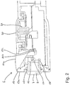
- Fig. 2 shows an example of a side sectional view through an embodiment of the measuring device 6.
- the coupling cushion 7, which receives the transmitting and receiving device 8 in the form of an elastic cap and a direct, for example dry, acoustic coupling of the transmitting and receiving device 8 to the wall 5 of the gas bottle 1.
- the coupling pad 7 designed as a cap is put over a rigid sleeve 15, for example made of a plastic, which, when the coupling pad 7 is pressed against the wall in the measuring device 6, for example axially along a perpendicular to the end face Longitudinal axis of the measuring device 6 is arranged movably.
- a finger 16 is formed on the sleeve 15, which can be resiliently movable, for example, and which can be pressed onto a microswitch 17 when the coupling cushion 7 is pressed, thereby causing the sleeve 15 to be pushed into the measuring device 6.
- the microswitch 17 which can be arranged for example on a circuit board of the evaluation device 9, the in Fig. 1 Illustrated measuring process can be triggered, for example, by generating the ultrasonic signal by the transmitting and receiving device 8.
- a limiter 18 can be provided, which forms a mechanical stop for the axial movability of the sleeve.
- the limiter 18 can consequently mechanically prevent the sleeve 15 from being pushed in with an excessive pressure and thus an excessive pressure from the finger 16 onto the microswitch 17. This enables effective protection of the switching mechanism of a measuring head comprising the coupling pad 7, the transmitting and receiving device 8, the sleeve 15 and the finger 16 even when the measuring head is pressed firmly against the wall 5 by the operator.
- the lighting device 10 is in the in Fig. 2
- the embodiment shown is formed, for example, by a light guide 10a consisting of a transparent plastic, which can direct a light of two colored light-emitting diodes 10b and 10c to an outside of the measuring device 6 that is visible to the operator. As a result, the display of the measurement result for the operator is easily visually detectable.
- the sleeve 15 is radially enclosed with the coupling pad 7 placed over it and the measuring head is enclosed by a glass body 19, for example made of a transparent plastic.
- the essentially rigid glass body 19 can, for example, form a mechanical stop when the coupling pad 7 is pressed against the wall 5 and thus provide additional protection against the application of excessive pressure to the switching mechanism of the measuring head.
- the glass body can lead out the light of a light-emitting diode (not shown) that can be switched by the operator from the measuring device 6 on the end face and thus enable good illumination of the wall 5 when the measuring head is applied to the wall 5.
- the glass body 19 can have corrugations 19a on the end face, which can prevent scratching of the surfaces of the glass body 19 set back behind the corrugations 19a.
- the light-emitting diode that shines through the glass body 19 can be switched, for example, by means of a button 20, by means of which an extension 21 can be pressed, for example, onto a further microswitch on the circuit board.
- the button 20 When the button 20 is actuated, the light-emitting diode can, for example, be switched on and off when the button 20 is released.
- Fig. 3 is the embodiment of the measuring device 6 from Fig. 2 shown in a perspective external view with a view of the end measuring head.
- the measuring device is enclosed by a compact plastic housing 22 in the form of a handpiece with an axial length of approximately 15 cm to a maximum of 20 cm, which can have a grip surface 23 for ergonomic design, for example.
- the compact, ergonomic design enables easy handling of the measuring device 6 when filling level.
- the coupling pad 7 located in front of the measuring head is surrounded axially about a longitudinal axis of the measuring device 6 by the glass body 19 provided on the end face with the corrugations 19a and having light outlets 19b and 19c.
- the light guide 10a of the lighting device 10 emerges from the plastic housing 22 of the measuring device 6 on a top side facing the face of the operator in a typical operating position and enables the measurement result to be output in a manner that is visually easy to understand.
- the button 20 for actuating the lighting device which illuminates the glass body 19 is arranged on the upper side.
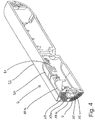
- Fig. 4 shows in perspective a lateral section through the plastic housing 22 of the measuring device 6, from which the arrangement of the button 20 with the underlying extension 21, the light guide 10a, the glass body 19 provided with the corrugations 19a and the protruding on the end of the measuring device 6 via the sleeve 15 coupling pad 7 slipped with the finger 16 can be seen.
- This embodiment illustrates the compact and ergonomic design of the measuring device 6 and illustrates the simple and intuitive one-hand operation by the operator.
Landscapes
- Physics & Mathematics (AREA)
- Acoustics & Sound (AREA)
- Electromagnetism (AREA)
- Thermal Sciences (AREA)
- Fluid Mechanics (AREA)
- General Physics & Mathematics (AREA)
- Measurement Of Levels Of Liquids Or Fluent Solid Materials (AREA)
Description
- Die Erfindung betrifft gemäß Patentanspruch 1 ein Messgerät zum Bestimmen eines Füllstands einer Flüssigkeit in einem Behälter. Das Messgerät kann insbesondere für den mobilen Einsatz und bei Behältern aller Art verwendet werden, beispielsweise zur Füllstandsbestimmung bei Flüssiggasbehältern z.B. im Campingbereich.
- Das Bestimmen eines Füllstands einer Flüssigkeit in einem Behälter ist immer dann problematisch, wenn der Behälter beispielsweise aus technischen Gründen nicht einsehbar ist und keine Füllstandsanzeigevorrichtung aufweist. Dies ist beispielsweise der Fall bei einem aus Metall gefertigten Behälter zum Aufbewahren und Bereitstellen von Flüssiggas, der wegen des vorliegenden Innendrucks nicht geöffnet werden kann.
- Derartige Gasflaschen werden beispielsweise im Campingbereich zum Kochen oder Heizen in einem Caravan oder Wohnmobil verwendet. Sie finden darüber hinaus auch beim Kochen oder Heizen in Haushalten oder beim Betreiben von Brennern, Heizpilzen oder Grillwagen im Gastronomiebereich Verwendung. Ähnliche Behältnisse, bei denen sich eine Füllstandsüberwachung schwierig oder aufwändig gestalten kann, finden sich auch in der Lebensmittelindustrie, im Bauhandwerk z.B. beim Betrieb technischer Brenner, im Versorgungsbereich z.B. bei der Bereitstellung von Flüssigchlor zur Wasseraufbereitung, oder bei der Feuerbekämpfung z.B. der Bereitstellung von Löschflüssigkeiten.
- Es ist bekannt, den Füllstand derartiger Flüssigkeitsbehälter beispielsweise durch Wiegen zu bestimmen. Dies ist allerdings oft ungenau, insbesondere wegen des hohen Taragewichts (Leergewichts) der Flüssiggasflaschen. Weiterhin muss das Leergewicht bekannt sein und die Flasche beispielsweise auf einer Waage platziert werden. Hierfür muss sie gegebenenfalls aus einem bestehenden System entnommen werden, z.B. von einer Entnahmevorrichtung abgekoppelt werden, was hohen Aufwand verursachen kann.
- Weiterhin ist ein Temperaturmessverfahren bekannt, bei dem die Temperatur eines aus einer Flüssiggasflasche ausströmenden Gases gemessen wird. Hieraus kann auf den Füllstand des Gases in der Flüssiggasflasche geschlossen werden. Dieses Verfahren ist allerdings fehleranfällig und ungenau und kann nur während einer Entnahme des Gases durchgeführt werden.
- Weiterhin ist es bekannt, Flüssigkeitsbehälter wie beispielsweise Tanks mit einem Schwimmersystem auszustatten, wobei das Schwimmersystem an eine Anzeigevorrichtung angekoppelt ist, über die ein Füllstand des Behälters anzeigbar ist. Derartige Schwimmersysteme sind allerdings teuer und somit für Wechselflaschen nicht sinnvoll einsetzbar. Zudem können die Schwimmersysteme bei mechanischen Einflüssen wie beispielsweise einem Schütteln des Tanks verklemmen.
- Darüber hinaus ist eine Füllstandsmessung mit Hilfe eines Ultraschallmesssystems bekannt, bei der ein Ultraschallsignal von unten durch eine Wand des Behälters in die Flüssigkeit eingeleitet wird. Anhand einer Laufzeit des Ultraschallsignals durch die Flüssigkeit und seines an einem oberen Flüssigkeitsspiegel am Übergang zwischen der Flüssigkeit und der Luft entstehenden Echos kann der Füllstand im Behälter berechnet werden.
- Ein derartiges Füllstandsmessgerät zeigt beispielsweise die
EP 0 955 529 A1 . Das Füllstandsmessgerät weist einen Anpressmechanismus auf, durch den ein mit einer Ultraschall-Ankoppelschicht fest verbundener Ultraschallwandler bei einem Aufbringen eines Behälters auf das Füllstandsmessgerät derart gegen den Behälter gepresst wird, dass sich die Ankoppelschicht an die Oberfläche des Behälters schmiegt. Bei einem Abnehmen des Behälters wird der Ultraschallwandler wieder vom Behälter gelöst. Mit dem Füllstandsmessgerät kann die Phasengrenze zwischen einem flüssigen und gasförmigen Medium der Gasflasche geortet und so der Füllstand ermittelt und angegeben werden. Allerdings ist es bei diesem Füllstandsmessgerät notwendig, den Behälter auf das Füllstandsmessgerät aufzusetzen. Dies macht es erforderlich, den Behälter aus einem bestehenden System herauszulösen, von einer Entnahmevorrichtung abzukoppeln und/oder auf dem Füllstandsmessgerät aufzubringen. Dies ist insbesondere dann problematisch, wenn den Behälter ein hohes Gewicht aufweist, was bei Flüssiggasflaschen häufig der Fall ist. - Die
DE 103 31 044 A1 zeigt eine Haltevorrichtung für einen Behälter und für eine Füllstandsmesseinrichtung. Die Haltevorrichtung ermöglicht es, in einer Offenstellung, in der eine Gasflasche beispielsweise mit großer Wucht in die Haltevorrichtung eingesetzt werden kann, die Füllstandsmesseinrichtung in einer Schutzstellung anzuordnen. In einer Geschlossenstellung kann die Füllstandsmesseinrichtung an eine Außenwand der Gasflasche gedrückt werden und eine Messung des Füllstands vorgenommen werden. Hieraus wird deutlich, dass das Vornehmen eines derartigen Messverfahrens mit einem hohen manuellen Aufwand und mit großer Belastung einhergeht. - In der
DE 197 11 093 C2 ist ein Gerät zur Bestimmung des Inhalts einer Flüssiggasflasche gezeigt, bei dem ein von einem Schallsensor ausgesendetes Sendesignal und ein von einem Schallempfänger empfangenes Empfangssignal mittels eines Mikroprozessors verglichen wird, wodurch eine für die Inhaltsmenge der Gasflasche charakteristische Resonanz der Gasflasche ermittelt werden kann. Das Verfahren ist wegen der Bestimmung der charakteristischen Resonanz der Gasflasche allerdings nur für Gasflaschen einer bestimmten Art und Größe und für ein bestimmtes Gas anwendbar, beispielsweise für 11 kg Propangasflaschen aus Stahl. Es benötigt eine lange Messzeit und ist fehleranfällig gegenüber allen Störungen, die sich auf die charakteristische Resonanz der Gasflasche auswirken können. - In der
DE 195 38 696 A1 ist zur Überwachung eines vorbestimmten Füllstands einer Flüssigkeit in einem Behälter ein Ultraschallwandler an der Außenseite des Behälters an einer Messstelle montiert, die auf der Höhe des zu überwachenden Füllstands liegt. Der Ultraschallwandler ist ortsfest mittels eines Adapters an der Behälterwand befestigt, beispielsweise verschraubt, verschweißt, geklebt oder mittels eines um den Behälter gelegten Spannbandes befestigt. Die Vorrichtung ist somit im Wesentlichen zur Anwendung an einem einzigen Behälter verwendbar, da sie mit diesem fest verbunden wird. Weiterhin kann lediglich der vorbestimmte Füllstand bestimmt werden. Sie ist damit zur einfachen Anwendung bzw. Erfassung eines beliebigen Füllstands beispielsweise an Wechselflaschen nicht geeignet. - Aus der
GB 2 126 342 A - In der
DE 20 2011 003 126 U1 ist ein Messgerät zur Messung eines Füllstands von Flüssigkeiten in einem Tank bekannt, wobei das Messgerät über Magnete am Tank angeordnet wird. Das Ergebnis der Messung des Füllstands wird dem Benutzer über eine Anzeigeeinheit angezeigt, die als grün leuchtende LED ausgeführt ist. - Ferner ist in der
EP 1 679 495 A2 ein Messgerät beschrieben, das zweiteilig aufgebaut ist, wobei in einem mobilen Teil lediglich die Empfangsvorrichtung, die Sendevorrichtung sowie die Koppelvorrichtung vorgesehen ist. - Aus der
US 2004/0035208 A1 ist ein pistolenartiger Teil eines Messgeräts bekannt, das eine Sendevorrichtung, eine Empfangsvorrichtung sowie eine Koppelvorrichtung umfasst. Ferner sind Status-LEDs an dem pistolenartiger Teil angeordnet. - Der Erfindung liegt die Aufgabe zugrunde, ein Messgerät zum Bestimmen eines Füllstands einer Flüssigkeit in einem Behälter anzugeben, welches kostengünstig und einfach handhabbar ist, und welches es ermöglicht, den Füllstand des Behälters schnell und ohne ein mechanisches Herauslösen des Behälters aus einem System, beispielsweise einem Entnahme- und/oder Verbrauchsystem, zu ermitteln.
- Diese Aufgabe wird durch ein Messgerät gemäß Patentanspruch 1 und durch ein Verfahren gemäß Patentanspruch 10 gelöst. Weiterentwicklungen der Erfindung sind den abhängigen Ansprüchen zu entnehmen.
- Die Sendevorrichtung zum Erzeugen der Ultraschallwellen kann das Ultraschallsignal in einer beliebigen Stärke und Frequenz, beispielsweise einmalig, mehrfach oder gepulst, aussenden. Sie kann einen Ultraschallwandler aufweisen, der elektrische Energie in Ultraschallenergie wandeln kann. Beispielsweise kann die Sendevorrichtung einen Lautsprecher aufweisen. Alternativ kann die Sendevorrichtung ein piezoelektrisches Element wie beispielsweise eine piezoelektrische Keramik oder einen piezoelektrischen Kristall mit aufgebrachten Elektroden aufweisen. Wenn an die Elektroden eine Wechselspannung angelegt wird, wird das piezoelektrische Element zu mechanischen Schwingungen mit der Frequenz der Wechselspannung angeregt und dadurch das Ultraschallsignal erzeugt.
- Die Empfangsvorrichtung zum Empfangen des Echos kann eine beliebige Empfangsvorrichtung für Ultraschallsignale sein und einen Ultraschallwandler wie beispielsweise ein Mikrofon oder ebenfalls ein piezoelektrisches Element mit darauf aufgebrachten Elektroden aufweisen. Wird das piezoelektrische Element durch empfangene Ultraschallwellen zu mechanischen Schwingungen angeregt, so wird zwischen den Elektroden eine Wechselspannung mit der Frequenz der mechanischen Schwingungen erzeugt. Hierdurch werden die Ultraschallwellen, beispielsweise das Echo des von der Sendevorrichtung gesendeten Ultraschallsignals, empfangbar und können beispielsweise an die Auswertevorrichtung elektrisch weitergeleitet werden.
- Die Koppelvorrichtung kann zum unmittelbaren Ankoppeln des Messgeräts bzw. der Koppelvorrichtung an eine Wand eines Behälters, dessen Füllstand zu bestimmen ist, geeignet sein. Beispielsweise kann das Ultraschallsignal von der Sendevorrichtung durch die Koppelvorrichtung in die Wand einleitbar und das Echo des Ultraschallsignals durch die Koppelvorrichtung aus der Wand zu der Empfangsvorrichtung ausleitbar sein. Durch Auswerten, beispielsweise Klassifizieren des Echos kann, wie im Folgenden näher beschrieben, das Messergebnis bestimmbar sein. Das Messergebnis kann beispielsweise angeben, ob sich in einem hinter einer Fläche der Wand, an der die Koppelvorrichtung angekoppelt ist, unmittelbar angrenzenden Bereich eines Inneren des Behälters eine Flüssigkeit befindet oder nicht. Der Bereich der Fläche der Wand, in dem die Koppelvorrichtung angekoppelt ist, wird im Folgenden auch als Koppelfläche bezeichnet.
- Der Behälter kann ein beliebiger Behälter zum Aufnehmen der Flüssigkeit sein. Der Behälter kann beispielsweise ein Tank, ein Fass, ein Kanister oder eine Röhre zur Flüssigkeitsleitung sein. Weiterhin kann eine einfache Beobachtung des Füllstands nicht möglich sein. Beispielsweise kann ein Einblick in das Innere des Behälters durch eine undurchsichtige Umwandung und/oder eine dunkle Umgebung erschwert oder unmöglich sein. Insbesondere kann es sich um einen Druckbehälter zur Aufnahme von Flüssiggas wie beispielsweise eine Gasflasche oder Gaskartusche handeln, in die wegen der stabilen Wände und wegen des hohen Innendrucks kein Einblick genommen werden kann. Derartige Gasflaschen können ein Volumen von bis zu 150 Litern besitzen und einen Druck von bis zu 300 bar aufweisen. Sie werden wegen des hohen Druckes beispielsweise aus Aluminium oder Stahl gefertigt und weisen daher häufig ein hohes Gewicht auf. Eine Füllstandsüberwachung mit den eingangs genannten bekannten Methoden gestaltet sich bei derartigen Gasflaschen daher schwierig.
- Das Messgerät kann zur Füllstandsbestimmung beispielsweise ein Verfahren verwenden, das darauf beruht, dass sich Ultraschallwellen in Gasen bzw. Flüssigkeiten unterschiedlich ausbreiten. In Flüssigkeiten breiten sich Ultraschallwellen im Wesentlichen dämpfungsarm aus. In Luft hingegen werden Ultraschallwellen stark gedämpft. Bei einem Phasenübergang, das heißt einem Durchtritt von einem festen, flüssigen oder gasförmigen Material in ein anderes, können Ultraschallwellen gebrochen oder gebeugt werden, und eine Interferenz zwischen den Ultraschallwellen kann auftreten. Demzufolge breiten sich Ultraschallwellen nachdem Einleiten in eine Flüssigkeit gut aus und werden an den Phasenübergängen beispielsweise zu einem Festkörper oder zu einem gasförmigen Medium reflektiert und als Echo zurückgeleitet. Nach einem Einleiten in Luft ist wegen der starken Dämpfung ein etwaiges Echo überhaupt nicht oder wenn, dann nur schwach zu empfangen.
- Ein Übergang von Ultraschallwellen in einen Festkörper oder eine Flüssigkeit erfolgt nur, wenn die Ultraschallwellen in unmittelbarer Nähe des Festkörpers bzw. der Flüssigkeit abgestrahlt werden, oder wenn ein Koppelmedium mit angepassten akustischen Eigenschaften zwischengelagert ist. Die Koppelvorrichtung kann beispielsweise ein derartiges Koppelmedium aufweisen und somit ein Einleiten des Ultraschallsignals in die Wand des Behälters und ein Ausleiten des Echos aus der Wand des Behälters ermöglichen.
- Die Koppelvorrichtung kann hierzu unmittelbar und direkt an die Wand des Behälters angekoppelt werden. Insbesondere kann das Koppeln direkt und ohne Lufteinschluss beispielsweise durch Andrücken bzw. Anpressen der Koppelvorrichtung an die Wand des Behälters erfolgen. Hierzu kann die Koppelvorrichtung als Koppelmedium beispielsweise ein elastisches Koppelkissen mit angepassten akustischen Eigenschaften, einer geeigneten Dicke und mit zur Auflage an der Wand vorgesehenen, beispielsweise glatten, geriffelten und/oder genoppten Auflageflächen aufweisen. Das Koppelkissen kann beim Andrücken direkt auf der Wand aufliegen und sich durch seine Elastizität dicht und im Wesentlichen ohne Lufteinschluss an die Wand anschmiegen.
- In dieser Position kann die Koppelvorrichtung bzw. das Koppelkissen als Schallleiter fungieren und das von der Sendevorrichtung erzeugte Ultraschallsignal in die Wand des Behälters einleiten. Ebenso kann die Koppelvorrichtung bzw. das Koppelkissen oder eine weitere Koppelvorrichtung bzw. ein weiteres Koppelkissen das Echo des Ultraschallsignals aus der Wand des Behälters aufnehmen und zur Empfangsvorrichtung ausleiten.
- Die Auswertevorrichtung kann beispielsweise das Aussenden des Ultraschallsignals durch die Sendevorrichtung steuern und auf dieser Basis bzw. mit Bezug auf das Ultraschallsignal das von der Empfangsvorrichtung empfangene Echo des Ultraschallsignals auswerten. Beispielsweise kann eine Ausprägung oder eine Qualität des Echos bestimmt, beispielsweise anhand messbarer Größen ermittelt werden. Die Ausprägung bzw. Qualität des Echos oder das Echo selbst können auf dieser Basis klassifiziert werden. Beispielsweise kann anhand messbarer Eigenschaften des Echos eine Klassifizierung, beispielsweise eine Zuordnung des Echos zu einer vorbestimmten Klasse, vorgenommen werden. Die Klassen können derart vorbestimmt sein, dass eine Klasse Echos umfasst, die entstehen können, wenn sich hinter der Koppelfläche im unmittelbar angrenzenden Bereich des Inneren des Behälters die Flüssigkeit befindet, und eine weitere Klasse Echos, die entstehen können, wenn sich dort keine Flüssigkeit befindet. Dies ermöglicht ein Bestimmen des Füllstands.
- Die Auswertevorrichtung kann beispielsweise eine Signalverarbeitungsvorrichtung aufweisen, zum Beispiel in Form eines auf einer Platine angeordneten, über Signalleitungen mit der Sendevorrichtung und der Empfangsvorrichtung verbundenen Mikroprozessors. Sie kann beispielsweise eine Frequenz, eine Stärke oder einen Puls des auszusendenden Ultraschallsignals vorgeben, und anschließend das Echo des ausgesendeten Ultraschallsignals im Hinblick auf seine Frequenz, seine Stärke oder seinen Puls auswerten. Beispielsweise kann das Echo vor dem Auswerten verstärkt und/oder gefiltert werden. Beispielsweise kann das Echo auf Basis seiner Frequenz, seiner Stärke oder seines Pulses klassifiziert bzw. bewertet werden.
- Wie bereits beschrieben, hängt das Echo bzw. seine Stärke, seine Frequenz oder sein Puls davon ab, ob sich hinter der Koppelfläche in einem unmittelbar dort angrenzenden Bereich des Inneren des Behälters die Flüssigkeit befindet oder nicht. Befindet sich dort eine Flüssigkeit, so kann das Ultraschallsignal sich dämpfungsarm in der Flüssigkeit ausbreiten und an einen Phasenübergang zu einem Festkörper oder einem gasförmigen Medium, beispielsweise an einer gegenüberliegenden Wand bzw. der dahinterliegenden Luft, oder an einer Oberfläche der Flüssigkeit reflektiert werden. Das so entstehende Echo des Ultraschallsignals kann sich in der Flüssigkeit ebenfalls dämpfungsarm ausbreiten und ist daher deutlich durch die Empfangsvorrichtung empfangbar. Befindet sich im Bereich des Inneren des Behälters hinter der Koppelfläche jedoch keine Flüssigkeit, sondern z.B. Luft oder ein Gas, so wird das Ultraschallsignal stark gedämpft. Das Ultraschallsignal wird daher nicht bis an die gegenüberliegende Wand oder bis an einen Flüssigkeitsspiegel geleitet, sondern vorher gedämpft. Ein Echo des Ultraschallsignals ist daher nicht oder nur sehr schwach durch die Empfangsvorrichtung empfangbar. Folglich kann das Echo nach einer Stärke seines Empfangs klassifiziert und beispielsweise einer Klasse "Signalübermittlung durch flüssiges Medium" oder "Signalübermittlung durch gasförmiges Medium" zugeordnet werden.
- Durch einen Abgleich des gesendeten Ultraschallsignals und des empfangenen Echos kann die Auswertevorrichtung daher mit einer hohen Genauigkeit bestimmen, ob sich hinter der Koppelfläche, also hinter der Fläche der Wand, an der die Koppelvorrichtung angekoppelt ist, eine Flüssigkeit befindet oder nicht. Dies kann durch die Klassifizierung des Echos angegeben werden und das Messergebnis der Auswertevorrichtung bestimmen.
- Das Messergebnis kann in beliebiger Weise durch die Ausgabevorrichtung ausgegeben, also für einen Bediener des Messgeräts erkennbar gemacht werden. Beispielsweise kann die Ausgabevorrichtung eine optische Anzeige wie beispielsweise ein Display oder eine Leuchtvorrichtung aufweisen, durch die das Messergebnis optisch ausgegeben werden kann. Alternativ oder zusätzlich kann die Ausgabevorrichtung auch einen Summer oder einen Lautsprecher aufweisen, durch die das Messergebnis akustisch, beispielsweise durch eine Sprachausgabe oder ein Tonsignal, ausgegeben werden kann.
- Durch das Ausgeben des Messergebnisses wird der Bediener darüber informiert, ob sich hinter der Koppelfläche die Flüssigkeit befindet oder nicht. Durch sukzessives Wiederholen des Messvorgangs, beispielsweise seitlich an dem Behälter auf unterschiedlichen Höhenniveaus, kann der Bediener den Füllstand in dem Behälter erfassen bzw. den Flüssigkeitsspiegel beliebig genau lokalisieren.
- Dies kann ohne eine Einflussnahme auf den Behälter oder seine Außenhaut, insbesondere ohne ein Öffnen oder Bewegen des Behälters geschehen. Am Behälter müssen keine besonderen Vorrichtungen vorgesehen sein, das Messgerät kann direkt auf einer glatten Außenhaut des Behälters aufgesetzt werden. Das Verfahren kann daher für beliebige Behälter angewendet werden. Insbesondere muss der Behälter nicht aus einer Position, in der er sich befindet, bewegt werden oder aus einem System, in dem er beispielsweise durch ein Ventil angeschlossen ist, abgekoppelt werden. Lediglich ein Teilbereich der Wand des Behälters muss für den direkten Kontakt mit dem Messgerät zugänglich sein. Die Messung kann in jeder Lage, beispielsweise an einem stehenden oder liegenden Behälter vorgenommen werden, und ist unabhängig davon, ob im Moment der Messung Gas entnommen wird oder nicht. Die Messung geht schnell vonstatten und ist für den Bediener mit nur geringem Aufwand verbunden. Durch eine Anpassung beispielsweise einer Auswertelogik bzw. einer Auswertesoftware der Auswertevorrichtung kann das Messgerät für den Einsatz an unterschiedlich gearteten Behältern aus unterschiedlichen Materialien wie beispielsweise Stahl, Aluminium oder Kunststoff, sowie an unterschiedliche Flüssigkeiten angepasst bzw. ausgelegt werden. Folglich erlaubt das Messgerät ein einfaches und kostengünstiges Bestimmen eines Füllstands einer beliebigen Flüssigkeit in einem beliebigen Behälter.
- Die Sendevorrichtung, die Empfangsvorrichtung, die Koppelvorrichtung, die Auswertevorrichtung und die Ausgabevorrichtung können in oder an einem mobilen, beispielsweise tragbaren Handstück angeordnet sein. Beispielsweise kann dass Handstück eine Länge von 15 cm oder 20 cm und ein Gewicht von 150 g oder 200 g aufweisen. Dies erlaubt die Gestaltung des Messgeräts als mobiles, tragbares und für den Benutzer einfach handhabbares Gerät, beispielsweise mit den Ausmaßen eines Mobiltelefons oder einer Taschenlampe. Das Messgerät kann daher auch dann einfach eingesetzt werden, wenn in einer Umgebung des Behälters nur wenig Raum zum Ankoppeln des Messgeräts vorhanden ist. Weiterhin kann das tragbare, mobile Messgerät zu verschiedenen Behältern mitgenommen werden, sodass mit nur einem Messgerät die Füllstände einer Vielzahl von Behältern erfasst werden können. Die Integration des Messgeräts in einem Handstück macht das Messgerät auch im häuslichen oder im Campingbereich einsetzbar und leicht handhabbar. Das manuelle Halten und Ankoppeln des handgehaltenen Messgeräts macht die Anwendung auch für den Laien und Privatmann einfach. Das Gehäuse des Handstücks kann beispielsweise aus Kunststoff in einem ergonomischen und attraktiven Design gestaltet sein.
- In einer Ausführungsform können die Sendevorrichtung, die Empfangsvorrichtung, die Auswertevorrichtung und/oder die Ausgabevorrichtung beispielsweise durch einen in dem Handstück angeordneten Energiespeicher mit elektrischer Energie versorgbar sein. Als elektrischer Energiespeicher können beispielsweise handelsübliche Batterien oder wiederaufladbare Akkumulatoren vorgesehen sein. Dies ermöglicht eine gute Verfügbarkeit des Messgeräts unabhängig von Zugängen zu einem Stromversorgungsnetz, sowie einen kostengünstigen Betrieb mit handelsüblichen Energiespeichern.
- In einer Ausführungsform kann die Koppelvorrichtung eine Kontakteinrichtung aufweisen, die Kontakteinrichtung zwischen einer Offenstellung und einer Geschlossenstellung bewegbar ist, und bei einem Erreichen der Geschlossenstellung das Ultraschallsignal sendbar, das Echo des Ultraschallsignals empfangbar und/oder das Messergebnis bestimmbar ist.
- Beispielsweise kann die Koppelvorrichtung durch ein Andrücken der Koppelvorrichtung an die Wand ankoppelbar und durch ein Lösen von der Wand abkoppelbar sein. Dies ermöglicht ein intuitives Auslösen des Messvorgangs bei gleichzeitig guter Positionierung der Koppelvorrichtung an der Wand des Behälters.
- Die Kontakteinrichtung kann beispielsweise als ein Schalter oder Mikroschalter mit der Koppelvorrichtung fest oder elastisch gekoppelt sein und beispielsweise beim Andrücken der Koppelvorrichtung an die Wand in die Geschlossenstellung bewegbar sein, wodurch der Messvorgang gestartet werden kann. Dies ermöglicht ein intuitives Auslösen des Messvorgangs durch den Bediener. In dieser Ausführungsform muss daher kein separater Schalter zum Auslösen des Messvorgangs durch den Bediener vorgesehen sein.
- Das Messgerät kann beispielsweise beim Erreichen der Geschlossenstellung durch die Kontakteinrichtung eingeschaltet und die Messung gestartet werden. Weiterhin kann das Messgerät beispielsweise nach einer vorgegebenen Zeitspanne, wie beispielsweise nach 20 Sekunden, innerhalb der keine Bedienvorgabe durch den Bediener an dem Messgerät gemacht wurde, automatisch wieder abgeschaltet werden. Dies ermöglicht eine einfache, intuitive Bedienung und schont den Energievorrat des Energiespeichers. Ein separater Schalter muss nicht vorgesehen werden.
- In einer Ausführungsform kann eine akustische Signalvorrichtung zum Ausgeben eines akustischen Signals beim Beenden des Bestimmens des Messergebnisses vorgesehen sein. In dieser Ausführungsform kann zur Information des Bedieners beim Einschalten des Geräts, beim Auslösen der Messung, beim Abschluss der Messung und/oder beim Ausschalten des Geräts ein beispielsweise akustisches Signal ausgegeben werden.
- In einer weiteren Ausführungsform kann die Koppelvorrichtung eine Federeinrichtung aufweisen, wobei die Kontakteinrichtung durch die Federeinrichtung in der Offenstellung haltbar ist.
- Die Federeinrichtung kann ein beliebiges Federelement aufweisen, wie beispielsweise eine Spiralfeder, einen Gummipuffer oder eine Gummikappe. Die Federeinrichtung kann mit der Kontakteinrichtung derart gekoppelt sein, dass die Federeinrichtung beispielsweise bei einem Entspannen die Kontakteinrichtung in die Offenstellung bewegt. Beim Bewegen der Kontakteinrichtung in die Geschlossenstellung, beispielsweise beim Andrücken der Koppelvorrichtung in die Wand, kann die Federeinrichtung gespannt werden. Folglich wird beim darauffolgenden Lösen von der Wand die Kontakteinrichtung automatisch in die Offenstellung bewegt.
- Folglich kann die Koppelvorrichtung die Funktion eines Druckschalters haben, der bei einem Drücken, also bei einem Andrücken der Koppelvorrichtung an die Wand des Behälters, bzw. bei einem Bewegen der Kontakteinrichtung in die Geschlossenstellung den Messvorgang auslöst. Nach dem Lösen der Koppelvorrichtung von der Wand stellt die Federeinrichtung sicher, dass die Kontakteinrichtung in die Offenstellung bewegt wird, sodass die Koppelvorrichtung bei einem erneuten Koppeln sofort einen neuen Messvorgang auslösen kann. Dies ermöglicht ein einfaches, intuitives Bedienen des Messgeräts und stellt eine gute akustische Kopplung sicher.
- In einer weiteren Ausführungsform weist die Koppelvorrichtung eine ein elastisches Material aufweisende Kappe auf. Die Sendevorrichtung und/oder die Empfangsvorrichtung können innerhalb der Kappe, beispielsweise unmittelbar angrenzend an eine Stirnseite der Kappe angeordnet sein. Die Kontakteinrichtung kann mit der Kappe gekoppelt sein.
- Durch das elastische Material kann sich die Kappe beispielsweise an die Wand anschmiegen bzw. sich der Form der Wand derart anpassen, dass ein Einschließen von Luft beim Ankoppeln verhindert werden kann. Die Außenseite der Kappe kann glatt sein, was ein gutes Ankoppeln der Kappe unter Ausschluss von Luft und somit eine gute akustische Ankopplung an die Behälterwand sicherstellt.
- Die Kappe kann aus einem Kunststoff bzw. Gummi bestehen und eine geeignete Dicke für eine gute akustische Ein- und Auskopplung aufweisen. Beispielsweise kann an der Stirnseite der Kappe das Koppelkissen mit einer eine gute akustische Kopplung sicherstellenden Dicke ausgeformt sein.
- Zusätzlich kann beim Ankoppeln beispielsweise an eine Unebenheiten aufweisende Wand ein beispielsweise viskoses Koppelgel wie beispielsweise ein Silikongel aufgebracht werden. Dies ist allerdings in den meisten Fällen nicht notwendig, da auch bei einer Trockenankopplung der Kappe ein eindeutiges Messergebnis erzielt werden kann.
- Die Sende- und/oder die Empfangsvorrichtung können innerhalb der Kappe beispielsweise an der Stirnseite und/oder unmittelbar angrenzend an das Koppelkissen angeordnet sein, was eine direkte Ein- bzw. Ausleitung des Ultraschallsignals bzw. seines Echos ermöglicht. Die Sende- und Empfangsvorrichtung können an dieser Position durch die Kappe gut gegen äußere Einflüsse geschützt werden, beispielsweise gegen ein Eindringen von Schmutz oder Flüssigkeit.
- Die Kontakteinrichtung kann mit der Kappe derart gekoppelt sein, dass durch ein Andrücken der Kappe die Kontakteinrichtung unmittelbar in die Geschlossenstellung bewegbar ist. Beispielsweise kann die Kontakteinrichtung an einem im Wesentlichen starren Kunststoffteil oder an einer Kunststoffhülse befestigt oder beispielsweise als Fortsatz oder Finger ausgeführt sein. Die Kappe kann über das Kunststoffteil bzw. die Kunststoffhülse gezogen sein. So kann bei einem Andrücken der Kappe die Kunststoffhülse axial entlang einer Längsachse des Messgeräts in das Messgerät hineingeschoben und dabei der Finger in die Geschlossenstellung bewegt werden und beispielsweise einen Mikroschalter betätigen.
- Die aus der Kunststoffhülse und der Kappe bestehende Einheit kann die innen liegenden, empfindlichen Teile der Sendevorrichtung, der Empfangsvorrichtung, der Kontakteinrichtung und des Mikroschalters sowie auch die Auswertevorrichtung vor äußeren Einflüssen schützen. Dies erhöht die Lebensdauer und Robustheit des Messgeräts.
- Weiterhin kann ein mechanischer Anschlag vorgesehen sein, der eine axiale Bewegung der Kunststoffhülse beim Aufdrücken der Kappe beschränkt. Hierdurch kann erreicht werden, dass die Kontakteinrichtung zwar mit einem bestimmten Druck in die Geschlossenstellung bewegbar sein kann, dass aber ein zu hoher Druck, welcher beispielsweise den in der Geschlossenstellung schaltbaren Mikroschalter zerstören oder den Finger beschädigen könnte, verhindert bzw. abgefangen werden kann.
- In dieser Ausführungsform kann die Kappe bei einem Nachlassen des Anpressdrucks gegen die Wand nach außen federn und dadurch die Kunststoffhülse nach außen ziehen. Hierdurch kann die mit der Kunststoffhülse gekoppelte Kontakteinrichtung aus der Geschlossenstellung in die Offenstellung bewegbar sein. Folglich kann die Kappe in dieser Ausführungsform die Funktion der Federeinrichtung übernehmen.
- In einer weiteren Variante kann die Sendevorrichtung, die Empfangsvorrichtung und/oder die Kontakteinrichtung mit der Kappe zu einem in dem Messgerät axial beweglichen Bauteil integriert und/oder vulkanisiert sein.
- Das Bauteil bildet einen integrierten Messkopf oder Mess- und Schaltkopf, der in dem Messgerät axial hin- und herbewegbar ist, und der beim Ankoppeln an die Wand des Behälters axial in das Messgerät hineingedrückt und beim Lösen von der Wand des Behälters aus dem Messgerät herausbewegt werden kann. Dies erleichtert ein einfaches Bedienen des Messgeräts, sorgt für eine geschützte Position der integrierten Sende- und Empfangsvorrichtung und erlaubt eine einfache Montage des Messgeräts in der Fertigung.
- In einer weiteren Ausführungsform weist das Messgerät einen die Sendevorrichtung und die Empfangsvorrichtung integrierenden Ultraschallwandler auf.
- Wie bereits beschrieben, kann der Ultraschallwandler eine Piezokeramik oder einen Piezokristall aufweisen, der, wenn über zwei Elektroden mit einer Wechselspannung beschickt, eine entsprechende Ultraschallwelle erzeugen kann, und der, wenn eine Ultraschallwelle mit einer bestimmten Frequenz auf ihn auftrifft, eine entsprechende Wechselspannung an den Elektroden erzeugt. Dies ermöglicht eine einfache und kostengünstige Gestaltung des Messgeräts.
- In einer weiteren Ausführungsform kann die Ausgabevorrichtung eine optische Signalvorrichtung aufweisen, wobei die optische Signalvorrichtung in Abhängigkeit von einem Messergebnis schaltbar sein kann.
- Beispielsweise kann die optische Signalvorrichtung beim Feststellen einer Flüssigkeit in dem Ankoppelbereich angeschaltet werden und beim Feststellen eines Gases in dem Ankoppelbereich nicht angeschaltet werden. Weiterhin können farbige Signalvorrichtungen, wie beispielsweise farbige Leuchtdioden (LED) in einer ersten und zweiten Farbe, zum Beispiel in Rot und Grün, vorgesehen sein. Beispielsweise kann beim Feststellen einer Flüssigkeit eine grüne Leuchtdiode angeschaltet werden, und beim Feststellen eines Gases bzw. von Luft eine rote Leuchtdiode. Eine weitere Leuchtdiode in einer dritten, beispielsweise gelben Farbe kann nach den Starten eines Messvorgangs bis zum Vorliegen des Messergebnisses und in sonstigen Betriebszuständen angeschaltet sein. Zusätzlich kann ein akustisches Signal beim Beenden der Messung ausgegeben werden.
- Das Licht der optischen Signalvorrichtung kann durch einen transparenten Lichtleiter an eine geeigneten Stelle des Messgeräts bzw. des Handstücks oder des Gehäuses geleitet und dort sichtbar für den Bediener abgestrahlt werden. Die Verwendung farbiger Leuchtdioden ermöglicht es, das Messergebnis intuitiv erfassbar für den Bediener auszugeben. Weiterhin kann die Ausgabevorrichtung auf diese Weise kostengünstig gestaltet sein, eine komplizierte Bild- oder Textanzeige ist nicht notwendig.
- Die Anschlagvorrichtung kann stirnseitig an dem Messgerät und in einer typischen Bedienstellung des Messgeräts beispielsweise seitlich, z.B. links und rechts neben der Koppelvorrichtung, angeordnet sein. Sie kann die Koppelvorrichtung axial entlang einer Längsachse des Messgeräts oder den Mess- und Schaltkopf axial umschließen. Sie kann ein Material mit einer höheren Festigkeit bzw. Steifigkeit als das der Koppelvorrichtung aufweisen.
- Das Vorsehen der Anschlagvorrichtung ermöglicht es dem Bediener, den Anstellwinkel beim Ankoppeln der Koppelvorrichtung an der Wand des Behälters zu kontrollieren und somit eine gute akustische Kopplung zu erreichen. Weiterhin kann durch die Anschlagvorrichtung das Messgerät vor einem zu hohen Druck geschützt werden. Insbesondere kann ein zu hoher Anpressdruck durch die Anschlagvorrichtung abgefangen werden. Ein zu geringer Druck wird wegen des fehlenden Anschlags für den Bediener haptisch erfassbar. Das starre Material kann beispielsweise ein Kunststoff oder ein Metall sein.
- Durch eine schaltbare Leuchtvorrichtung kann Licht im Bereich der Koppelvorrichtung derart abgestrahlt werden, dass die Wand des Behälters beim Hinführen des Messgeräts beleuchtet und so die Wahl einer geeigneten Ankoppelfläche bzw. Anpressstelle unterstützt werden kann. Dies erleichtert insbesondere die Füllstandsmessung von Behältern an dunklen, schwer zugänglichen Stellen. Durch die schaltbare Leuchtvorrichtung kann eine Beleuchtung nur dann erzeugt und Energie hierfür nur dann aufgewendet werden, wenn der Bediener dies für hilfreich hält und die Leuchtvorrichtung anschaltet.
- Das lichtdurchlässige Material kann ein transparenter Kunststoff sein, der durch die Leuchtvorrichtung, beispielsweise durch eine oder mehrere Leuchtdioden, durchleuchtbar ist.
- Die Anschlagvorrichtung kann beispielsweise als Glaskörper oder als Körper aus einem transparenten Kunststoff den die Koppelvorrichtung beinhaltenden Messkopf des Messgeräts radial umschließen, was eine gute Positionierung und Ausleuchtung beim Koppeln ermöglicht. Um ein Verkratzen einer Außenfläche des Glaskörpers zu verhindern oder zu verringern, kann der Glaskörper eine geeignete Oberflächengestaltung aufweisen, beispielsweise mit Vorsprüngen bzw. schmalen Riffeln zum Anstoßen an der Wand und mit zurückgesetzten, breiteren Flächen, die in dieser Lage vor einem Verkratzen geschützt sind.
- Ein Verfahren zum Bestimmen eines Füllstands einer Flüssigkeit in einem Behälter mit Hilfe eines Messgeräts wie vorstehend beschrieben weist einen Messvorgang auf mit einem Andrücken der Koppelvorrichtung an eine seitliche Wand des Behälters auf einem Höhenniveau, einem Erzeugen des Ultraschallsignals durch die Sendevorrichtung und einem Einleiten des Ultraschallsignals in die Wand durch die Koppelvorrichtung, einem Ausleiten des Echos aus der Wand durch die Koppelvorrichtung und einem Erfassen des Echos durch die Empfangsvorrichtung, einem Bestimmen des Messergebnisses auf Basis einer Klassifizierung des Echos, wobei das Messergebnis angibt, ob sich in einem hinter einer Fläche der Wand, an der die Koppelvorrichtung angekoppelt ist, unmittelbar angrenzenden Bereich eines Inneren des Behälters eine Flüssigkeit befindet oder nicht, und einem Ausgeben des Messergebnisses durch die Ausgabevorrichtung, sowie ein Ausleuchten eines um die Koppelvorrichtung gelegenen Bereichs auf Anforderung durch einen Bediener über die schaltbare Leuchtvorrichtung im Bereich der Koppelvorrichtung.
- Das Verfahren kann eine beliebige Ausführungsform des vorstehend beschriebenen Messgeräts verwenden. Die Koppelvorrichtung des Messgeräts wird in dem Verfahren an eine seitliche Wand des Behälters auf einem beispielsweise durch den Bediener beliebig zu wählenden Höhenniveau angedrückt. Durch das Ausgeben des Messergebnisses, welches in der vorstehend beschriebenen Weise gewonnen wird, wird der Bediener darüber informiert, ob sich in dem Koppelbereich, in dem die Koppelvorrichtung an der Wand angekoppelt ist, hinter der Wand eine Flüssigkeit befindet oder nicht. Entsprechend kann der Bediener abschätzen, ob ein Füllstand bzw. Flüssigkeitspegel in dem Behälter oberhalb oder unterhalb des Höhenniveaus ist. Dies ermöglicht ein einfaches, intuitives Abschätzen des Füllstands durch den Bediener, wie beispielsweise ein Prüfen, ob ein minimaler Füllstand noch enthalten ist.
- Eine Ausführungsform des Verfahrens weist ein Auslösen des Messvorgangs durch Andrücken der Koppelvorrichtung an die Wand an.
- Durch das Andrücken der Koppelvorrichtung an die Wand kann, wie oben beschrieben, beispielsweise die Kontaktvorrichtung in die Geschlossenstellung bewegt werden und so der Messvorgang ausgelöst werden. Dies ermöglicht ein intuitives Auslösen des Messvorgangs ohne ein separates Betätigen beispielsweise eines Schalters durch den Bediener. Ein Ende des Messvorgangs kann dem Bediener beispielsweise durch ein akustisches Signal angezeigt werden. Ein separates Bedienelement zum Auslösen und/oder Beenden des Messvorgangs muss an dem Messgerät daher nicht vorgesehen sein. Das Messgerät kann beispielsweise nach einem vorgegebenen Zeitraum, in dem der Bediener keine Bedienvorgabe gemacht hat, ausgeschaltet werden.
- Beispielsweise kann auf Anforderung des Bedieners durch Betätigen eines Tasters die oben beschriebene, im Wesentlichen aus einem lichtdurchlässigen Material bestehende Anschlagvorrichtung durch die Leuchtvorrichtung durchleuchtet werden. Dies ermöglicht es dem Bediener, auch in einem unzugänglichen, dunklen Bereich eine geeignete Koppelfläche an der Wand des Behälters zu erkennen und das Messgerät geeignet anzukoppeln. Weiterhin kann eine derartige Taschenlampenfunktion den Bediener auch außerhalb des Messvorgangs unterstützen und so die Akzeptanz des Messgeräts erhöhen.
- Der Füllstand kann durch Wiederholen des Messvorgangs mit Andrücken der Koppelvorrichtung an die seitliche Wand auf einem weiteren Höhenniveau abgeschätzt werden. Beispielsweise kann der Bediener den Messvorgang sukzessive und mehrfach auf verschiedenen Höhenniveaus durchführen. Dies ermöglicht es ihm, den Füllstand des Behälters mit beliebiger Genauigkeit abzuschätzen. Da für das Auslösen des Messvorgangs lediglich das Andrücken der Koppelvorrichtung an die Wand und darüber hinaus keine weitere Bedienvorgabe notwendig sein kann, kann der Messvorgang mit nur sehr geringem Aufwand durch den Bediener wiederholt werden.
- Diese und weitere Merkmale der Erfindung werden nachfolgend anhand von Beispielen unter Zuhilfenahme der begleitenden Figuren näher erläutert. Es zeigen:
- Fig. 1
- eine Flüssiggasflasche und ein Messgerät zum Bestimmen eines Füllstands in der Flüssiggasflasche;
- Fig. 2
- eine Ausführungsform des Messgeräts aus
Fig. 1 in einer seitlichen Schnittansicht; - Fig. 3
- die Ausführungsform aus
Fig. 2 in einer perspektivischen Außenansicht; und - Fig. 4
- eine perspektivische Schnittansicht der Ausführungsform aus
Fig. 2 -
Fig. 1 zeigt schematisch in einer seitlichen Schnittansicht eine Gasflasche 1 mit einem Standfuß 2, welche mit einem Flüssiggas 3 teilweise befüllt ist. Oberhalb eines Oberflächenspiegels 3a des Flüssiggases 3 ist eine Luft 4 in der Gasflasche 1 eingeschlossen. - Seitlich an einer Wand 5 der Gasflasche 1 ist ein Messgerät 6 angeordnet, welches über ein Koppelkissen 7 eine unmittelbare Kopplung zwischen der Wand 5 der Gasflasche 1 und einer piezokeramischen Sende- und Empfangsvorrichtung 8 des Messgeräts 6 herstellt. Das beispielsweise aus einem elastischen Kunststoff bestehende Koppelkissen 7 erlaubt so eine direkte, Luft ausschließende akustische Trockenankopplung der Sende- und Empfangsvorrichtung 8 an die Wand 5 der Gasflasche 1.
- Die Sende- und Empfangsvorrichtung 8 ist elektronisch mit einer Auswertevorrichtung 9 des Messgeräts 6 verbunden, welche beispielsweise einen Mikroprozessor auf einer Platine aufweisen kann. Die Auswertevorrichtung 9 ist mit einer z.B. eine Leuchtdiode aufweisenden Leuchtvorrichtung 10 verbunden, durch die ein Auswerteergebnis der Auswertevorrichtung 9 ausgegeben, also für einen Bediener des Messgeräts 6 optisch erfassbar gemacht wird. Die Sende- und Empfangsvorrichtung 8, die Auswertevorrichtung 9 und die Leuchtvorrichtung 10 sind aus einer Batterie 11 mit elektrischer Energie versorgbar.
- In dem Messgerät 6 kann beispielsweise bei einem Andrücken des Koppelkissens 7 an die Wand 5 ein Mikroschalter (nicht gezeigt) betätigt werden, der ein Senden eines Ultraschallsignals durch die Sende- und Empfangsvorrichtung 8 auslöst. Das Ultraschallsignal kann durch die akustische Ankopplung an die Wand 5 in die Wand 5 und durch diese in das hinter der Wand befindliche Flüssiggas 3 eingeleitet werden. Da das Ultraschallsignal, wie durch einen ersten Pfeil 12 illustriert, im Wesentlichen ungedämpft durch das Flüssiggas 3 bis zu einem gegenüberliegenden Abschnitt der Wand 5 geleitet wird, entsteht an dem gegenüberliegenden Abschnitt der Wand 5 ein Echo des Ultraschallsignals, welches, wie durch einen zweiten Pfeil 13 illustriert, ebenfalls im Wesentlichen ungedämpft durch das Flüssiggas 3 und durch die Wand 5 über das Koppelkissen 7 zur Sende- und Empfangsvorrichtung 8 reflektiert werden kann. In der Sende- und Empfangsvorrichtung 8 kann das empfangene Echo in ein elektronisches Signal gewandelt und zur Auswertevorrichtung 9 geleitet werden.
- Die Auswertevorrichtung 9 kann auf Basis des empfangenen Echos ein Messergebnis bestimmen, welches angibt, ob sich hinter der Fläche der Wand 5, an der das Koppelkissen 7 angekoppelt ist, das Flüssiggas 3 oder die Luft 4 befindet. An der Leuchtvorrichtung 10 kann das Messergebnis beispielsweise durch Schalten einer farbigen Leuchtdiode in einer ersten Farbe angezeigt werden.
- In
Fig. 1 ist das Messgerät 6 mit gestrichelten Linien in einer weiteren Position 6' gezeigt, in der das von der Sende- und Empfangsvorrichtung 8 erzeugte Ultraschallsignal über das Koppelkissen 7 an einer Koppelfläche der Wand 5 eingeleitet wird, hinter der sich nicht das Flüssiggas 3, sondern die Luft 4 befindet. Wie durch den kurzen Pfeil 14 dargestellt, wird das Ultraschallsignal in der Luft 4 stark gedämpft, sodass ein Echo des Ultraschallsignals nicht empfangbar oder kaum messbar ist. Dies kann durch die Auswertevorrichtung 9 erkannt und beispielsweise durch Ansteuern einer weiteren farbigen Leuchtdiode beispielsweise in einer weiteren Farbe dem Bediener angezeigt werden. - Durch ein wiederholtes Ausführen des Messvorgangs kann der Bediener den Oberflächenspiegel 3a des Flüssiggases 3 eingrenzen, lokalisieren und so den Füllstand des Flüssiggases 3 in der Gasflasche 1 erfassen. Die Gasflasche 1 muss hierzu nicht bewegt oder beispielsweise von einem Anschlussventil abgekoppelt werden. Eine Messung des Füllstands ist in jeder Lage der Gasflasche 1 möglich und unabhängig davon, ob zum Zeitpunkt der Messung das Flüssiggas 3 aus der Gasflasche 1 entnommen wird oder nicht. Die Messung kann schnell und einfach durch Andrücken des Koppelkissens 7 an die Wand 5 durchgeführt werden. Das Messergebnis wird intuitiv beispielsweise durch eine farbige Beleuchtung der Leuchtvorrichtung 10 angezeigt. Da der Messvorgang durch Andrücken des Koppelkissens 7 ausgelöst werden kann, ist hierzu kein weiteres Bedienelement an dem Messgerät 6 und keine weitere Bedienhandlung des Bedieners notwendig.
-
Fig. 2 zeigt beispielhaft eine seitliche Schnittansicht durch eine Ausführungsform des Messgeräts 6. An einer in der Zeichnung links dargestellten Stirnseite des Messgeräts 6 befindet sich das Koppelkissen 7, das in Form einer elastischen Kappe die Sende- und Empfangsvorrichtung 8 aufnimmt und eine direkte, beispielsweise trockene akustische Kopplung der Sende- und Empfangsvorrichtung 8 zu der Wand 5 der Gasflasche 1 ermöglicht. Das als Kappe ausgebildete Koppelkissen 7 ist über eine starre, beispielsweise aus einem Kunststoff gefertigte Hülse 15 gestülpt, welche bei einem Andrücken des Koppelkissens 7 an die Wand in dem Messgerät 6 beispielsweise axial entlang einer senkrecht zur Stirnseite stehenden Längsachse des Messgeräts 6 beweglich angeordnet ist. An der Hülse 15 ist ein Finger 16 ausgebildet, welcher beispielsweise federnd beweglich sein kann und welcher bei einem Andrücken des Koppelkissens 7 mit einem dadurch verursachten Einschieben der Hülse 15 in das Messgerät 6 auf einen Mikroschalter 17 gedrückt werden kann. Durch das Andrücken des Mikroschalters 17, welcher beispielsweise auf einer Platine der Auswertevorrichtung 9 angeordnet sein kann, kann der inFig. 1 illustrierte Messvorgang beispielsweise durch Erzeugen des Ultraschallsignals durch die Sende- und Empfangsvorrichtung 8 ausgelöst werden. - Um die axiale Bewegbarkeit der Hülse 15 innerhalb des Messgeräts 6 zu begrenzen, kann ein Begrenzer 18 vorgesehen sein, der einen mechanischen Anschlag der axialen Bewegbarkeit der Hülse bildet. Durch den Begrenzer 18 kann folglich ein Einschieben der Hülse 15 mit einem zu starken Druck und damit ein Aufbringen eines zu hohen Drucks durch den Finger 16 auf den Mikroschalter 17 mechanisch verhindert werden. Dies ermöglicht einen effektiven Schutz der Schaltmechanik eines das Koppelkissen 7, die Sende- und Empfangsvorrichtung 8, die Hülse 15 und den Finger 16 umfassenden Messkopfs auch bei einem kräftigen Andrücken des Messkopfs an die Wand 5 durch den Bediener.
- Die Leuchtvorrichtung 10 wird in der in
Fig. 2 gezeigten Ausführungsform durch einen beispielsweise aus einem transparenten Kunststoff bestehenden Lichtleiter 10a gebildet, welcher ein Licht zweier farbiger Leuchtdioden 10b und 10c an eine für den Bediener sichtbare Außenseite des Messgeräts 6 leiten kann. Hierdurch wird die Anzeige des Messergebnisses für den Bediener einfach optisch erfassbar. - In der gezeigten Ausführungsform ist die Hülse 15 mit dem übergestülpten Koppelkissen 7 radial und den Messkopf umschließend von einem beispielsweise aus einem transparenten Kunststoff bestehenden Glaskörper 19 umschlossen. Der im Wesentlichen starre Glaskörper 19 kann beispielsweise einen mechanischen Anschlag beim Andrücken des Koppelkissens 7 an die Wand 5 bilden und so einen zusätzlichen Schutz vor dem Aufbringen eines zu hohen Drucks auf die Schaltmechanik des Messkopfs bilden.
- Weiterhin kann der Glaskörper das Licht einer durch den Bediener schaltbaren Leuchtdiode (nicht gezeigt) aus dem Messgerät 6 stirnseitig ausleiten und so eine gute Beleuchtung der Wand 5 beim Aufbringen des Messkopfs auf die Wand 5 ermöglichen. Der Glaskörper 19 kann stirnseitig Riffel 19a aufweisen, die ein Verkratzen der hinter den Riffeln 19a zurückgesetzten Oberflächen des Glaskörpers 19 verhindern können.
- Die den Glaskörper 19 durchleuchtende Leuchtdiode kann beispielsweise mittels eines Tasters 20, durch welchen ein Fortsatz 21 beispielsweise auf einen weiteren Mikroschalter der Platine gedrückt werden kann, geschaltet werden. Bei einem Betätigen des Tasters 20 kann die Leuchtdiode beispielsweise ein- und bei einem Loslassen des Tasters 20 ausgeschaltet werden.
- In
Fig. 3 ist die Ausführungsform des Messgeräts 6 ausFig. 2 in einer perspektivischen Außenansicht mit Blick auf den stirnseitigen Messkopf gezeigt. - Das Messgerät ist von einem kompakten Kunststoffgehäuse 22 in Form eines Handstücks mit einer axialen Länge von ungefähr 15 cm bis maximal 20 cm umschlossen, welches zur ergonomischen Gestaltung beispielsweise eine Grifffläche 23 aufweisen kann. Die kompakte, ergonomische Gestaltung ermöglicht eine einfache Handhabung des Messgeräts 6 bei der Füllstandserfassung.
- Das am Messkopf stirnseitig vorgelagerte Koppelkissen 7 ist axial um eine Längsachse des Messgeräts 6 von dem stirnseitig mit den Riffeln 19a versehenen Glaskörper 19 mit Lichtauslässen 19b und 19c umgeben. An einer in einer typischen Bedienhaltung dem Gesicht des Bedieners zugewandten Oberseite tritt der Lichtleiter 10a der Leuchtvorrichtung 10 aus dem Kunststoffgehäuse 22 des Messgeräts 6 und ermöglicht eine visuell einfach erfassbare Ausgabe des Messergebnisses. Weiterhin ist an der Oberseite der Taster 20 zum Betätigen der den Glaskörper 19 durchleuchtenden Leuchtvorrichtung angeordnet.
-
Fig. 4 zeigt perspektivisch einen seitlichen Schnitt durch das Kunststoffgehäuse 22 des Messgeräts 6, aus der die Anordnung des Tasters 20 mit dem darunterliegenden Fortsatz 21, des Lichtleiters 10a, des mit den Riffeln 19a versehenen Glaskörpers 19 und des stirnseitig an dem Messgerät 6 vorstehenden, über die Hülse 15 mit dem Finger 16 gestülpten Koppelkissens 7 ersichtlich ist. Diese Ausführungsform illustriert die kompakte und ergonomische Ausgestaltung des Messgeräts 6 und verdeutlicht die einfache und intuitive Ein-Hand-Bedienung durch den Bediener.
Claims (11)
- Messgerät (6) zur Füllstandsbestimmung an einem Behälter von außerhalb, mit- einer Sendevorrichtung (8) zum Aussenden eines Ultraschallsignals;- einer Empfangsvorrichtung (8) zum Empfangen eines Echos des Ultraschallsignals;- einer Koppelvorrichtung (7) zum Ausleiten des Ultraschallsignals von der Sendevorrichtung (8) und zum Einleiten des Echos des Ultraschallsignals zu der Empfangsvorrichtung;- einer Auswertevorrichtung (9) zum Bestimmen eines Messergebnisses auf Basis einer Klassifizierung des von der Empfangsvorrichtung (8) empfangenen Echos des Ultraschallsignals, wobei das Messergebnis angibt, ob sich in einem hinter einer Fläche der Behälterwand, an der die Koppelvorrichtung (7) angekoppelt ist, unmittelbar angrenzenden Bereich eines Inneren des Behälters eine Flüssigkeit befindet oder nicht; und- einer Ausgabevorrichtung (10) zum Ausgeben des Messergebnisses; wobei- die Sendevorrichtung (8), die Empfangsvorrichtung (8), die Koppelvorrichtung (7), die Auswertevorrichtung (9) und die Ausgabevorrichtung (10) in oder an einem mobilen Handstück angeordnet sind, wobei- eine schaltbare Leuchtvorrichtung im Bereich der Koppelvorrichtung (7) angeordnet ist, und wobei- an wenigstens zwei gegenüberliegenden Seiten der Koppelvorrichtung (7) eine Anschlagvorrichtung (19) aus einem im Wesentlichen starren, lichtdurchlässigen Material angeordnet ist, das im Wesentlichen durch die Leuchtvorrichtung durchleuchtbar ist, und- ein Anstellwinkel der Koppelvorrichtung (7) beim Ankoppeln der Koppelvorrichtung (7) an eine Wand (5) des Behälters durch die Anschlagvorrichtung (19) begrenzbar ist.
- Messgerät (6) nach Anspruch 1, wobei- die Koppelvorrichtung (7) eine Kontakteinrichtung (15, 16) aufweist,- die Kontakteinrichtung (15, 16) zwischen einer Offenstellung, in der sich ein Schalter in seiner geöffneten Stellung befindet, und einer Geschlossenstellung bewegbar ist, in der sich der Schalter in seiner geschlossenen Stellung befindet, und- bei einem Erreichen der Geschlossenstellung die Sendevorrichtung (8) eingerichtet ist, das Ultraschallsignal zu senden, die Empfangsvorrichtung (8) eingerichtet ist, das Echo des Ultraschallsignals zu empfangen und/oder die Auswerteeinheit eingerichtet ist, das Messergebnis zu bestimmen.
- Messgerät (6) nach Anspruch 2, wobei- die Koppelvorrichtung (7) eine Federeinrichtung (7) aufweist, und- die Kontakteinrichtung (15, 16) durch die Federeinrichtung (7) in der Offenstellung haltbar ist.
- Messgerät (6) nach Anspruch 2 oder 3, wobei- die Koppelvorrichtung (7) axial beweglich entlang einer Längsachse des Messgeräts (6) in dem Handstück angeordnet ist; und- die Koppelvorrichtung (7), die Sendevorrichtung (8) und/oder die Empfangsvorrichtung (8) bei einem Bewegen der Kontakteinrichtung in die Geschlossenstellung in das Handstück einschiebbar sind.
- Messgerät (6) nach einem der Ansprüche 2 bis 4, wobei- die Koppelvorrichtung (7) eine ein elastisches Material aufweisende Kappe aufweist,- die Sendevorrichtung (8) und/oder die Empfangsvorrichtung (8) Bestandteile der Kappe sind und innerhalb der Kappe unmittelbar angrenzend an einer Stirnseite der Kappe angeordnet sind, und- die Kontakteinrichtung (15, 16) mit der Kappe gekoppelt ist.
- Messgerät (6) nach einem der Ansprüche 2 bis 5, wobei- die Sendevorrichtung (8), die Empfangsvorrichtung (8) und/oder die Kontakteinrichtung (15, 16) mit der Kappe zu einem in dem Messgerät axial entlang einer Längsachse des Messgeräts (6) beweglichen Bauteil integriert und/oder vulkanisiert sind.
- Messgerät (6) nach einem der vorstehenden Ansprüche, mit- einem die Sendevorrichtung (8) und die Empfangsvorrichtung (8) integrierenden Ultraschallwandler (8).
- Messgerät (6) nach einem der vorstehenden Ansprüche, wobei- die Ausgabevorrichtung (10) eine optische Signalvorrichtung (10, 10a, 10b, 10c) aufweist, wobei die optische Signalvorrichtung (10, 10a, 10b, 10c) in Abhängigkeit von dem Messergebnis schaltbar ist.
- Messgerät (6) nach einem der vorstehenden Ansprüche, wobei- das Messgerät (6) eine akustische Signalvorrichtung zum Ausgeben eines akustischen Signals beim Beenden des Bestimmens des Messergebnisses aufweist.
- Verfahren zum Bestimmen eines Füllstands einer Flüssigkeit (3) in einem Behälter (1) mit Hilfe eines Messgeräts (6) nach einem der vorstehenden Ansprüche in einem Messvorgang mit:- Andrücken der Koppelvorrichtung (7) an eine seitliche Wand (5) des Behälters (1) auf einem Höhenniveau;- Erzeugen des Ultraschallsignals durch die Sendevorrichtung (8) und Einleiten des Ultraschallsignals in die Wand durch die Koppelvorrichtung (7);- Ausleiten des Echos aus der Wand durch die Koppelvorrichtung (7) und Erfassen des Echos durch die Empfangsvorrichtung (8);- Bestimmen des Messergebnisses durch die Auswertevorrichtung (9) auf Basis einer Klassifizierung des Echos, wobei das Messergebnis angibt, ob sich in einem hinter einer Fläche der Wand (5), an der die Koppelvorrichtung (7) angekoppelt ist, unmittelbar angrenzenden Bereich eines Inneren des Behälters (1) eine Flüssigkeit (3) befindet oder nicht;- Ausgeben des Messergebnisses durch die Ausgabevorrichtung (10); und- Ausleuchten eines um die Koppelvorrichtung (7) gelegenen Bereichs auf Anforderung durch einen Bediener über die schaltbare Leuchtvorrichtung im Bereich der Koppelvorrichtung.
- Verfahren nach Anspruch 10, mit- Auslösen des Messvorgangs durch Andrücken der Koppelvorrichtung (7) an die Wand (5).
Priority Applications (1)
| Application Number | Priority Date | Filing Date | Title |
|---|---|---|---|
| EP11006823.6A EP2559978B1 (de) | 2011-08-19 | 2011-08-19 | Mobiles Ultraschall-Messgerät zur Füllstandsbestimmung bei Behältern aller Art |
Applications Claiming Priority (1)
| Application Number | Priority Date | Filing Date | Title |
|---|---|---|---|
| EP11006823.6A EP2559978B1 (de) | 2011-08-19 | 2011-08-19 | Mobiles Ultraschall-Messgerät zur Füllstandsbestimmung bei Behältern aller Art |
Publications (2)
| Publication Number | Publication Date |
|---|---|
| EP2559978A1 EP2559978A1 (de) | 2013-02-20 |
| EP2559978B1 true EP2559978B1 (de) | 2020-02-26 |
Family
ID=44763729
Family Applications (1)
| Application Number | Title | Priority Date | Filing Date |
|---|---|---|---|
| EP11006823.6A Active EP2559978B1 (de) | 2011-08-19 | 2011-08-19 | Mobiles Ultraschall-Messgerät zur Füllstandsbestimmung bei Behältern aller Art |
Country Status (1)
| Country | Link |
|---|---|
| EP (1) | EP2559978B1 (de) |
Families Citing this family (6)
| Publication number | Priority date | Publication date | Assignee | Title |
|---|---|---|---|---|
| AU201712794S (en) | 2016-11-23 | 2017-05-23 | Dometic Sweden Ab | Ventilation and air conditioning apparatus |
| CN106768186B (zh) * | 2017-02-10 | 2023-04-07 | 桂林新洲机械设备有限公司 | 高精度大型饲料储料罐储料高度测量显示装置 |
| AU2018366469B2 (en) | 2017-11-16 | 2024-09-12 | Dometic Sweden Ab | Air conditioning apparatus for recreational vehicles |
| USD905217S1 (en) | 2018-09-05 | 2020-12-15 | Dometic Sweden Ab | Air conditioning apparatus |
| IT201900019193A1 (it) | 2019-10-17 | 2021-04-17 | Dometic Sweden Ab | Apparato di condizionamento dell'aria per veicoli ricreativi |
| EP4653825A1 (de) * | 2024-05-24 | 2025-11-26 | Honeywell International Inc. | Berührungsloser niveauschalter |
Family Cites Families (8)
| Publication number | Priority date | Publication date | Assignee | Title |
|---|---|---|---|---|
| GB2126342A (en) * | 1982-09-06 | 1984-03-21 | Innovative Tech Ltd | Liquid level detector |
| DE19538696C2 (de) | 1995-10-17 | 1997-09-25 | Endress Hauser Gmbh Co | Anordnung zur Überwachung eines vorbestimmten Füllstands einer Flüssigkeit in einem Behälter |
| DE19711093C2 (de) | 1996-09-23 | 2002-04-11 | Reich Kg Regel & Sicherheits | Gerät zur Bestimmung des Inhalts einer Gasflasche |
| DE19820482C1 (de) | 1998-05-07 | 1999-07-01 | Truma Geraetetechnik Gmbh & Co | Füllstandsmeßgerät |
| US6938488B2 (en) * | 2002-08-21 | 2005-09-06 | Battelle Memorial Institute | Acoustic inspection device |
| DE10331044B4 (de) | 2003-07-09 | 2007-01-04 | Truma Gerätetechnik GmbH & Co. | Haltevorrichtung für einen Behälter und für eine Füllstandsmesseinrichtung |
| US7360417B2 (en) * | 2005-01-10 | 2008-04-22 | Gems Sensors, Inc. | Fluid level detector |
| DE202011003126U1 (de) * | 2011-02-23 | 2011-05-05 | Gaslock Gmbh | Vorrichtung zur Messung des Füllstands von Flüssigkeiten |
-
2011
- 2011-08-19 EP EP11006823.6A patent/EP2559978B1/de active Active
Non-Patent Citations (1)
| Title |
|---|
| None * |
Also Published As
| Publication number | Publication date |
|---|---|
| EP2559978A1 (de) | 2013-02-20 |
Similar Documents
| Publication | Publication Date | Title |
|---|---|---|
| DE202011110687U1 (de) | Mobiles Messgerät zur Füllbestandsbestimmung bei Behältern aller Art | |
| EP2559978A1 (de) | Mobiles Ultraschall-Messgerät zur Füllstandsbestimmung bei Behältern aller Art | |
| EP3526542B1 (de) | Terahertz-messgerät zur ermittlung einer schichtdicke eines prüfobjektes und entsprechendes messverfahren | |
| US6938488B2 (en) | Acoustic inspection device | |
| EP2247927A1 (de) | Verfahren zur zustandsüberprüfung einer pipette, pipettierverfahren, pipettiervorrichtung und saugrohr für eine pipettiervorrichtung | |
| EP0961106A1 (de) | Füllstandsmessgerät zur Messung des Füllstands eines Füllguts in einem Behälter | |
| DE202012013077U1 (de) | Vorrichtung zur Messung des Füllstands von Flüssigkeiten | |
| EP2801798A1 (de) | Füllstandsmessgerät mit Spüleinrichtung | |
| US8911891B2 (en) | Battery electrolyte level detector apparatus | |
| EP4286890A3 (de) | Tdr-wandler | |
| EP2639788B1 (de) | Ultraschallsensor | |
| DE102017106045B4 (de) | Verfahren zur Kalibration eines Füllstandmessgeräts und Anord-nung aus einem Füllstandmessgerät und einem Reflektor zur Durchführung des Verfahrens | |
| AT17018U1 (de) | ||
| DE202011003126U1 (de) | Vorrichtung zur Messung des Füllstands von Flüssigkeiten | |
| DE102007061187A1 (de) | Vorrichtung zur Positionsbestimmung eines Schwimmerkörpers und Vorrichtung zur Aufnahme einer Flüssigkeit | |
| EP1801549A3 (de) | Hohlleiter für ein Mikrowellen-Füllstandsmessgerät | |
| DE4119147A1 (de) | Nachweisgeraet fuer aktiv abstrahlende flaechen von ultraschall-schwingern | |
| EP3620238B1 (de) | Ultraschallbehandlungsvorrichtung zum behandeln eines bauteils | |
| EP0831308B1 (de) | Gerät zur Bestimmung des Füllstands einer Flüssiggasflasche | |
| EP1659421A3 (de) | Sensor zur Überwachung des Nahbereichs an einem Kraftfahrzeug | |
| EP1186869A3 (de) | Füllstandsmessvorrichtung | |
| DE102014112368A1 (de) | Messvorrichtung zum Charakterisieren eines Prüflings mittels Ultraschall | |
| LU101301B1 (de) | Blutuntersuchungsgerät | |
| WO2009021755A3 (de) | Doppelkolbenstange | |
| WO2021244919A1 (de) | Ultraschallwandler und verfahren zum betrieb eines ultraschallwandlers |
Legal Events
| Date | Code | Title | Description |
|---|---|---|---|
| PUAI | Public reference made under article 153(3) epc to a published international application that has entered the european phase |
Free format text: ORIGINAL CODE: 0009012 |
|
| AK | Designated contracting states |
Kind code of ref document: A1 Designated state(s): AL AT BE BG CH CY CZ DE DK EE ES FI FR GB GR HR HU IE IS IT LI LT LU LV MC MK MT NL NO PL PT RO RS SE SI SK SM TR |
|
| AX | Request for extension of the european patent |
Extension state: BA ME |
|
| 17P | Request for examination filed |
Effective date: 20130820 |
|
| RBV | Designated contracting states (corrected) |
Designated state(s): AL AT BE BG CH CY CZ DE DK EE ES FI FR GB GR HR HU IE IS IT LI LT LU LV MC MK MT NL NO PL PT RO RS SE SI SK SM TR |
|
| 17Q | First examination report despatched |
Effective date: 20160622 |
|
| GRAP | Despatch of communication of intention to grant a patent |
Free format text: ORIGINAL CODE: EPIDOSNIGR1 |
|
| STAA | Information on the status of an ep patent application or granted ep patent |
Free format text: STATUS: GRANT OF PATENT IS INTENDED |
|
| INTG | Intention to grant announced |
Effective date: 20190926 |
|
| GRAS | Grant fee paid |
Free format text: ORIGINAL CODE: EPIDOSNIGR3 |
|
| GRAA | (expected) grant |
Free format text: ORIGINAL CODE: 0009210 |
|
| STAA | Information on the status of an ep patent application or granted ep patent |
Free format text: STATUS: THE PATENT HAS BEEN GRANTED |
|
| AK | Designated contracting states |
Kind code of ref document: B1 Designated state(s): AL AT BE BG CH CY CZ DE DK EE ES FI FR GB GR HR HU IE IS IT LI LT LU LV MC MK MT NL NO PL PT RO RS SE SI SK SM TR |
|
| REG | Reference to a national code |
Ref country code: GB Ref legal event code: FG4D Free format text: NOT ENGLISH |
|
| REG | Reference to a national code |
Ref country code: CH Ref legal event code: EP |
|
| REG | Reference to a national code |
Ref country code: AT Ref legal event code: REF Ref document number: 1238212 Country of ref document: AT Kind code of ref document: T Effective date: 20200315 |
|
| REG | Reference to a national code |
Ref country code: IE Ref legal event code: FG4D Free format text: LANGUAGE OF EP DOCUMENT: GERMAN |
|
| REG | Reference to a national code |
Ref country code: DE Ref legal event code: R096 Ref document number: 502011016486 Country of ref document: DE |
|
| PG25 | Lapsed in a contracting state [announced via postgrant information from national office to epo] |
Ref country code: RS Free format text: LAPSE BECAUSE OF FAILURE TO SUBMIT A TRANSLATION OF THE DESCRIPTION OR TO PAY THE FEE WITHIN THE PRESCRIBED TIME-LIMIT Effective date: 20200226 Ref country code: FI Free format text: LAPSE BECAUSE OF FAILURE TO SUBMIT A TRANSLATION OF THE DESCRIPTION OR TO PAY THE FEE WITHIN THE PRESCRIBED TIME-LIMIT Effective date: 20200226 Ref country code: NO Free format text: LAPSE BECAUSE OF FAILURE TO SUBMIT A TRANSLATION OF THE DESCRIPTION OR TO PAY THE FEE WITHIN THE PRESCRIBED TIME-LIMIT Effective date: 20200526 |
|
| REG | Reference to a national code |
Ref country code: NL Ref legal event code: MP Effective date: 20200226 |
|
| REG | Reference to a national code |
Ref country code: LT Ref legal event code: MG4D |
|
| PG25 | Lapsed in a contracting state [announced via postgrant information from national office to epo] |
Ref country code: BG Free format text: LAPSE BECAUSE OF FAILURE TO SUBMIT A TRANSLATION OF THE DESCRIPTION OR TO PAY THE FEE WITHIN THE PRESCRIBED TIME-LIMIT Effective date: 20200526 Ref country code: IS Free format text: LAPSE BECAUSE OF FAILURE TO SUBMIT A TRANSLATION OF THE DESCRIPTION OR TO PAY THE FEE WITHIN THE PRESCRIBED TIME-LIMIT Effective date: 20200626 Ref country code: SE Free format text: LAPSE BECAUSE OF FAILURE TO SUBMIT A TRANSLATION OF THE DESCRIPTION OR TO PAY THE FEE WITHIN THE PRESCRIBED TIME-LIMIT Effective date: 20200226 Ref country code: LV Free format text: LAPSE BECAUSE OF FAILURE TO SUBMIT A TRANSLATION OF THE DESCRIPTION OR TO PAY THE FEE WITHIN THE PRESCRIBED TIME-LIMIT Effective date: 20200226 Ref country code: HR Free format text: LAPSE BECAUSE OF FAILURE TO SUBMIT A TRANSLATION OF THE DESCRIPTION OR TO PAY THE FEE WITHIN THE PRESCRIBED TIME-LIMIT Effective date: 20200226 Ref country code: GR Free format text: LAPSE BECAUSE OF FAILURE TO SUBMIT A TRANSLATION OF THE DESCRIPTION OR TO PAY THE FEE WITHIN THE PRESCRIBED TIME-LIMIT Effective date: 20200527 |
|
| PG25 | Lapsed in a contracting state [announced via postgrant information from national office to epo] |
Ref country code: NL Free format text: LAPSE BECAUSE OF FAILURE TO SUBMIT A TRANSLATION OF THE DESCRIPTION OR TO PAY THE FEE WITHIN THE PRESCRIBED TIME-LIMIT Effective date: 20200226 |
|
| PG25 | Lapsed in a contracting state [announced via postgrant information from national office to epo] |
Ref country code: EE Free format text: LAPSE BECAUSE OF FAILURE TO SUBMIT A TRANSLATION OF THE DESCRIPTION OR TO PAY THE FEE WITHIN THE PRESCRIBED TIME-LIMIT Effective date: 20200226 Ref country code: SM Free format text: LAPSE BECAUSE OF FAILURE TO SUBMIT A TRANSLATION OF THE DESCRIPTION OR TO PAY THE FEE WITHIN THE PRESCRIBED TIME-LIMIT Effective date: 20200226 Ref country code: RO Free format text: LAPSE BECAUSE OF FAILURE TO SUBMIT A TRANSLATION OF THE DESCRIPTION OR TO PAY THE FEE WITHIN THE PRESCRIBED TIME-LIMIT Effective date: 20200226 Ref country code: DK Free format text: LAPSE BECAUSE OF FAILURE TO SUBMIT A TRANSLATION OF THE DESCRIPTION OR TO PAY THE FEE WITHIN THE PRESCRIBED TIME-LIMIT Effective date: 20200226 Ref country code: LT Free format text: LAPSE BECAUSE OF FAILURE TO SUBMIT A TRANSLATION OF THE DESCRIPTION OR TO PAY THE FEE WITHIN THE PRESCRIBED TIME-LIMIT Effective date: 20200226 Ref country code: SK Free format text: LAPSE BECAUSE OF FAILURE TO SUBMIT A TRANSLATION OF THE DESCRIPTION OR TO PAY THE FEE WITHIN THE PRESCRIBED TIME-LIMIT Effective date: 20200226 Ref country code: PT Free format text: LAPSE BECAUSE OF FAILURE TO SUBMIT A TRANSLATION OF THE DESCRIPTION OR TO PAY THE FEE WITHIN THE PRESCRIBED TIME-LIMIT Effective date: 20200719 Ref country code: CZ Free format text: LAPSE BECAUSE OF FAILURE TO SUBMIT A TRANSLATION OF THE DESCRIPTION OR TO PAY THE FEE WITHIN THE PRESCRIBED TIME-LIMIT Effective date: 20200226 Ref country code: ES Free format text: LAPSE BECAUSE OF FAILURE TO SUBMIT A TRANSLATION OF THE DESCRIPTION OR TO PAY THE FEE WITHIN THE PRESCRIBED TIME-LIMIT Effective date: 20200226 |
|
| REG | Reference to a national code |
Ref country code: DE Ref legal event code: R097 Ref document number: 502011016486 Country of ref document: DE |
|
| PLBE | No opposition filed within time limit |
Free format text: ORIGINAL CODE: 0009261 |
|
| STAA | Information on the status of an ep patent application or granted ep patent |
Free format text: STATUS: NO OPPOSITION FILED WITHIN TIME LIMIT |
|
| PG25 | Lapsed in a contracting state [announced via postgrant information from national office to epo] |
Ref country code: IT Free format text: LAPSE BECAUSE OF FAILURE TO SUBMIT A TRANSLATION OF THE DESCRIPTION OR TO PAY THE FEE WITHIN THE PRESCRIBED TIME-LIMIT Effective date: 20200226 |
|
| 26N | No opposition filed |
Effective date: 20201127 |
|
| PG25 | Lapsed in a contracting state [announced via postgrant information from national office to epo] |
Ref country code: SI Free format text: LAPSE BECAUSE OF FAILURE TO SUBMIT A TRANSLATION OF THE DESCRIPTION OR TO PAY THE FEE WITHIN THE PRESCRIBED TIME-LIMIT Effective date: 20200226 Ref country code: PL Free format text: LAPSE BECAUSE OF FAILURE TO SUBMIT A TRANSLATION OF THE DESCRIPTION OR TO PAY THE FEE WITHIN THE PRESCRIBED TIME-LIMIT Effective date: 20200226 |
|
| PG25 | Lapsed in a contracting state [announced via postgrant information from national office to epo] |
Ref country code: MC Free format text: LAPSE BECAUSE OF FAILURE TO SUBMIT A TRANSLATION OF THE DESCRIPTION OR TO PAY THE FEE WITHIN THE PRESCRIBED TIME-LIMIT Effective date: 20200226 |
|
| REG | Reference to a national code |
Ref country code: CH Ref legal event code: PL |
|
| PG25 | Lapsed in a contracting state [announced via postgrant information from national office to epo] |
Ref country code: LU Free format text: LAPSE BECAUSE OF NON-PAYMENT OF DUE FEES Effective date: 20200819 Ref country code: CH Free format text: LAPSE BECAUSE OF NON-PAYMENT OF DUE FEES Effective date: 20200831 Ref country code: LI Free format text: LAPSE BECAUSE OF NON-PAYMENT OF DUE FEES Effective date: 20200831 |
|
| REG | Reference to a national code |
Ref country code: BE Ref legal event code: MM Effective date: 20200831 |
|
| PG25 | Lapsed in a contracting state [announced via postgrant information from national office to epo] |
Ref country code: IE Free format text: LAPSE BECAUSE OF NON-PAYMENT OF DUE FEES Effective date: 20200819 Ref country code: BE Free format text: LAPSE BECAUSE OF NON-PAYMENT OF DUE FEES Effective date: 20200831 |
|
| REG | Reference to a national code |
Ref country code: AT Ref legal event code: MM01 Ref document number: 1238212 Country of ref document: AT Kind code of ref document: T Effective date: 20200819 |
|
| PG25 | Lapsed in a contracting state [announced via postgrant information from national office to epo] |
Ref country code: AT Free format text: LAPSE BECAUSE OF NON-PAYMENT OF DUE FEES Effective date: 20200819 |
|
| PG25 | Lapsed in a contracting state [announced via postgrant information from national office to epo] |
Ref country code: TR Free format text: LAPSE BECAUSE OF FAILURE TO SUBMIT A TRANSLATION OF THE DESCRIPTION OR TO PAY THE FEE WITHIN THE PRESCRIBED TIME-LIMIT Effective date: 20200226 Ref country code: MT Free format text: LAPSE BECAUSE OF FAILURE TO SUBMIT A TRANSLATION OF THE DESCRIPTION OR TO PAY THE FEE WITHIN THE PRESCRIBED TIME-LIMIT Effective date: 20200226 Ref country code: CY Free format text: LAPSE BECAUSE OF FAILURE TO SUBMIT A TRANSLATION OF THE DESCRIPTION OR TO PAY THE FEE WITHIN THE PRESCRIBED TIME-LIMIT Effective date: 20200226 |
|
| PG25 | Lapsed in a contracting state [announced via postgrant information from national office to epo] |
Ref country code: MK Free format text: LAPSE BECAUSE OF FAILURE TO SUBMIT A TRANSLATION OF THE DESCRIPTION OR TO PAY THE FEE WITHIN THE PRESCRIBED TIME-LIMIT Effective date: 20200226 Ref country code: AL Free format text: LAPSE BECAUSE OF FAILURE TO SUBMIT A TRANSLATION OF THE DESCRIPTION OR TO PAY THE FEE WITHIN THE PRESCRIBED TIME-LIMIT Effective date: 20200226 |
|
| P01 | Opt-out of the competence of the unified patent court (upc) registered |
Effective date: 20230514 |
|
| PGFP | Annual fee paid to national office [announced via postgrant information from national office to epo] |
Ref country code: DE Payment date: 20250827 Year of fee payment: 15 |
|
| PGFP | Annual fee paid to national office [announced via postgrant information from national office to epo] |
Ref country code: GB Payment date: 20250827 Year of fee payment: 15 |
|
| PGFP | Annual fee paid to national office [announced via postgrant information from national office to epo] |
Ref country code: FR Payment date: 20250825 Year of fee payment: 15 |