EP2559950A2 - Aufbau von aufgewärmter und gepumpter Sekundärflüssigkeit als Rückfluss nach Flüssigkeit - Google Patents
Aufbau von aufgewärmter und gepumpter Sekundärflüssigkeit als Rückfluss nach Flüssigkeit Download PDFInfo
- Publication number
- EP2559950A2 EP2559950A2 EP12180890A EP12180890A EP2559950A2 EP 2559950 A2 EP2559950 A2 EP 2559950A2 EP 12180890 A EP12180890 A EP 12180890A EP 12180890 A EP12180890 A EP 12180890A EP 2559950 A2 EP2559950 A2 EP 2559950A2
- Authority
- EP
- European Patent Office
- Prior art keywords
- fluid
- secondary fluid
- thermal energy
- flowpath
- heat exchanger
- Prior art date
- Legal status (The legal status is an assumption and is not a legal conclusion. Google has not performed a legal analysis and makes no representation as to the accuracy of the status listed.)
- Granted
Links
Images













Classifications
-
- F—MECHANICAL ENGINEERING; LIGHTING; HEATING; WEAPONS; BLASTING
- F24—HEATING; RANGES; VENTILATING
- F24D—DOMESTIC- OR SPACE-HEATING SYSTEMS, e.g. CENTRAL HEATING SYSTEMS; DOMESTIC HOT-WATER SUPPLY SYSTEMS; ELEMENTS OR COMPONENTS THEREFOR
- F24D5/00—Hot-air central heating systems; Exhaust gas central heating systems
- F24D5/02—Hot-air central heating systems; Exhaust gas central heating systems operating with discharge of hot air into the space or area to be heated
-
- F—MECHANICAL ENGINEERING; LIGHTING; HEATING; WEAPONS; BLASTING
- F24—HEATING; RANGES; VENTILATING
- F24F—AIR-CONDITIONING; AIR-HUMIDIFICATION; VENTILATION; USE OF AIR CURRENTS FOR SCREENING
- F24F1/00—Room units for air-conditioning, e.g. separate or self-contained units or units receiving primary air from a central station
- F24F1/0007—Indoor units, e.g. fan coil units
- F24F1/0043—Indoor units, e.g. fan coil units characterised by mounting arrangements
- F24F1/0047—Indoor units, e.g. fan coil units characterised by mounting arrangements mounted in the ceiling or at the ceiling
-
- F—MECHANICAL ENGINEERING; LIGHTING; HEATING; WEAPONS; BLASTING
- F24—HEATING; RANGES; VENTILATING
- F24F—AIR-CONDITIONING; AIR-HUMIDIFICATION; VENTILATION; USE OF AIR CURRENTS FOR SCREENING
- F24F1/00—Room units for air-conditioning, e.g. separate or self-contained units or units receiving primary air from a central station
- F24F1/01—Room units for air-conditioning, e.g. separate or self-contained units or units receiving primary air from a central station in which secondary air is induced by injector action of the primary air
-
- F—MECHANICAL ENGINEERING; LIGHTING; HEATING; WEAPONS; BLASTING
- F24—HEATING; RANGES; VENTILATING
- F24F—AIR-CONDITIONING; AIR-HUMIDIFICATION; VENTILATION; USE OF AIR CURRENTS FOR SCREENING
- F24F13/00—Details common to, or for air-conditioning, air-humidification, ventilation or use of air currents for screening
- F24F13/30—Arrangement or mounting of heat-exchangers
-
- F—MECHANICAL ENGINEERING; LIGHTING; HEATING; WEAPONS; BLASTING
- F28—HEAT EXCHANGE IN GENERAL
- F28F—DETAILS OF HEAT-EXCHANGE AND HEAT-TRANSFER APPARATUS, OF GENERAL APPLICATION
- F28F9/00—Casings; Header boxes; Auxiliary supports for elements; Auxiliary members within casings
- F28F9/02—Header boxes; End plates
- F28F9/026—Header boxes; End plates with static flow control means, e.g. with means for uniformly distributing heat exchange media into conduits
- F28F9/0265—Header boxes; End plates with static flow control means, e.g. with means for uniformly distributing heat exchange media into conduits by using guiding means or impingement means inside the header box
- F28F9/0268—Header boxes; End plates with static flow control means, e.g. with means for uniformly distributing heat exchange media into conduits by using guiding means or impingement means inside the header box in the form of multiple deflectors for channeling the heat exchange medium
-
- F—MECHANICAL ENGINEERING; LIGHTING; HEATING; WEAPONS; BLASTING
- F24—HEATING; RANGES; VENTILATING
- F24D—DOMESTIC- OR SPACE-HEATING SYSTEMS, e.g. CENTRAL HEATING SYSTEMS; DOMESTIC HOT-WATER SUPPLY SYSTEMS; ELEMENTS OR COMPONENTS THEREFOR
- F24D19/00—Details
- F24D19/008—Details related to central heating radiators
- F24D19/0087—Fan arrangements for forced convection
-
- F—MECHANICAL ENGINEERING; LIGHTING; HEATING; WEAPONS; BLASTING
- F28—HEAT EXCHANGE IN GENERAL
- F28D—HEAT-EXCHANGE APPARATUS, NOT PROVIDED FOR IN ANOTHER SUBCLASS, IN WHICH THE HEAT-EXCHANGE MEDIA DO NOT COME INTO DIRECT CONTACT
- F28D21/00—Heat-exchange apparatus not covered by any of the groups F28D1/00 - F28D20/00
- F28D2021/0019—Other heat exchangers for particular applications; Heat exchange systems not otherwise provided for
- F28D2021/0035—Other heat exchangers for particular applications; Heat exchange systems not otherwise provided for for domestic or space heating, e.g. heating radiators
-
- F—MECHANICAL ENGINEERING; LIGHTING; HEATING; WEAPONS; BLASTING
- F28—HEAT EXCHANGE IN GENERAL
- F28F—DETAILS OF HEAT-EXCHANGE AND HEAT-TRANSFER APPARATUS, OF GENERAL APPLICATION
- F28F2250/00—Arrangements for modifying the flow of the heat exchange media, e.g. flow guiding means; Particular flow patterns
- F28F2250/08—Fluid driving means, e.g. pumps, fans
-
- Y—GENERAL TAGGING OF NEW TECHNOLOGICAL DEVELOPMENTS; GENERAL TAGGING OF CROSS-SECTIONAL TECHNOLOGIES SPANNING OVER SEVERAL SECTIONS OF THE IPC; TECHNICAL SUBJECTS COVERED BY FORMER USPC CROSS-REFERENCE ART COLLECTIONS [XRACs] AND DIGESTS
- Y02—TECHNOLOGIES OR APPLICATIONS FOR MITIGATION OR ADAPTATION AGAINST CLIMATE CHANGE
- Y02B—CLIMATE CHANGE MITIGATION TECHNOLOGIES RELATED TO BUILDINGS, e.g. HOUSING, HOUSE APPLIANCES OR RELATED END-USER APPLICATIONS
- Y02B30/00—Energy efficient heating, ventilation or air conditioning [HVAC]
Definitions
- the present invention utilizes a pressurized thermal energy fluid to pass through a heat exchanger having flowpath (100) and a fluid actuation device (200) installed in a fluid actuation device assembly (20) in series connection, parallel connection or series-parallel connection for allowing the heat exchanger having flowpath (100) to release the thermal energy and the fluid actuation device (200) installed in the fluid actuation device assembly (20) to generate the rotary kinetic energy, thereby directly or through a magnetic non-contact insulation type transmission device (210) driving a secondary fluid pump set (202) to pump the secondary fluid to pass through a flowpath structure of secondary fluid (500) and a flow guide plate of secondary fluid (600) and the heat exchanger having flowpath (100) installed in a building, and then to enter a temperature differentiation body space configured by secondary fluid in the interior of the building, wherein a part of the secondary fluid with thermal energy passing the heat exchanger having flowpath (100) and the temperature differentiation body space returns as
- a conventional heat exchanger having a fluid pipeline for allowing thermal energy fluid to pass through often utilizes the external mechanical rotary kinetic energy or power of an electric motor to drive a fluid pump set to rotate, and then further to drive the air flow to pass through the heat exchanger thereby increasing the heat exchange efficiency of the heat exchanger, primary drawbacks thereof are increasing the cost for installation and increasing the consumed energy, in addition, the air flow with thermal energy is pumped to an opened space and a reflux operation is not provided, thus thermal energy would be unnecessarily dissipated.
- the present invention utilizes a pressurized thermal energy fluid to pass through a heat exchanger having flowpath (100) and a fluid actuation device (200) installed in a fluid actuation device assembly (20) in series connection, parallel connection or series-parallel connection for allowing the heat exchanger having flowpath (100) to release the thermal energy and the fluid actuation device (200) installed in the fluid actuation device assembly (20) to generate the rotary kinetic energy, thereby directly or through a magnetic non-contact insulation type transmission device (210) driving a secondary fluid pump set (202) to pump the secondary fluid to pass the heat exchanger having flowpath (100), such that the heat exchanger having flowpath (100) is enabled to perform thermal releasing of cooling or heating to the secondary fluid, and the mentioned components are installed in a closed type or semi-opened building, and the fluid actuation device (200) driven by the thermal energy fluid is utilized to drive the secondary fluid pump set (202) for pumping the secondary fluid to pass through a
- a heat exchanger includes a heat exchange pipeline (105) through which a heat exchange fluid is pumped; a secondary fluid flowpath (500) arranged to direct the secondary fluid over the heat exchange pipeline; and a fluid pump (202) disposed in the heat exchanger pipeline so as to be driven by the flow of heat exchange fluid and arranged so as to pump at least a part of the secondary fluid from an outlet (750) through the secondary fluid flowpath.
- a conventional heat exchanger having a fluid pipeline for allowing thermal energy fluid to pass through often utilizes the external mechanical rotary kinetic energy or power of an electric motor to drive a fluid pump set to rotate, and then further to drive the air flow to pass through the heat exchanger thereby increasing the heat exchange efficiency of the heat exchanger, primary drawbacks thereof are increasing the cost for installation and increasing the consumed energy, in addition, the air flow with thermal energy is pumped to an opened space and a reflux operation is not provided, thus thermal energy would be unnecessarily dissipated;
- the present invention utilizes a pressurized thermal energy fluid to pass through a heat exchanger having flowpath (100) and a fluid actuation device (200) installed in a fluid actuation device assembly (20) in series connection, parallel connection or series-parallel connection for allowing the heat exchanger having flowpath (100) to release the thermal energy and the fluid actuation device (200) installed in the fluid actuation device assembly (20) to
- the building warmed and pumped secondary fluid as reflux by fluid is structured through the fluid kinetic energy and thermal energy of a pressurized thermal energy source, which mainly consists of:
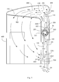
- FIG. 3 is a lateral structural view showing the present invention being applied in a semi-opened building, wherein the heat exchanger having flowpath (100) being installed in the flowpath structure of secondary fluid (500) and close to the secondary fluid outlet port (750), according to one embodiment of the present invention;
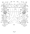
- FIG. 4 is a front view of the embodiment disclosed in FIG. 3 ;
- the building warmed and pumped secondary fluid as reflux by fluid is structured through the fluid kinetic energy and thermal energy of a pressurized thermal energy source, which mainly consists of:
- FIG. 5 is a lateral structural view showing the present invention being applied in a closed type building, wherein the heat exchanger having flowpath (100) being installed in the flowpath structure of secondary fluid (500) and close to the fluid actuation device assembly (20), according to one embodiment of the present invention;
- FIG. 6 is a front view of the embodiment disclosed in FIG. 5 ;
- the building warmed and pumped secondary fluid as reflux by fluid is structured through the flowing kinetic energy and thermal energy of a pressurized thermal energy source, which mainly consists of:
- FIG. 7 is a lateral structural view showing the present invention being applied in a closed type building, wherein the heat exchanger having flowpath (100) being installed in the flowpath structure of secondary fluid (500) and close to the secondary fluid outlet port (750), according to one embodiment of the present invention;
- FIG. 8 is a front view of the embodiment disclosed in FIG. 7 ;
- the building warmed and pumped secondary fluid as reflux by fluid is structured through the fluid kinetic energy and thermal energy of a pressurized thermal energy source, which mainly consists of:
- the secondary fluid is configured by liquid fluid, and the thermal energy fluid can be gaseous or liquid thermal energy fluid, and disposed in a tank-shaped, pool-shaped or sealed space;
- one or both of the secondary fluid inlet port (700) and the secondary fluid outlet port (750) can be further installed with an inlet port protection net of secondary fluid (800), or an outlet port protection net of secondary fluid (900);
- the thermal energy fluid from the thermal energy fluid source can be further in series installed with a thermal energy fluid pump (1201) having the function of boosting the fluid pressure;
- the thermal energy fluid pipeline (105) can be further in series installed with a flow regulation valve of thermal energy fluid (1202) for regulating the flow amount of thermal energy fluid;
- a same building can be provided with two or more than two sets of thermally actuated and pumped secondary fluid as reflux systems, which includes two or more than two sets of heat exchangers with flowpath (100), fluid actuation device assemblies (20) containing fluid actuation devices (200) and secondary fluid pump sets (202), thermal energy fluid pipelines (105), flowpath structures of secondary fluid (500), flow guide plates of secondary fluid (600) and secondary fluid inlet ports (700), thereby to structure the building warmed and pumped secondary fluid as reflux by fluid, and to form the circulative pumping of partial secondary fluid;
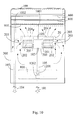
- Fig. 9 is a schematic view showing plural sets of the structure disclosed in FIG. 1 being installed, according to one embodiment of the present invention.
- FIG. 10 is a front view of the embodiment disclosed in FIG. 9 ;
- the building warmed and pumped secondary fluid as reflux by fluid is structured through the fluid kinetic energy and thermal energy of a pressurized thermal energy source, which mainly consists of:
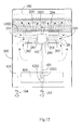
- Fig. 11 is a schematic view showing plural sets of the structure disclosed in FIG. 3 being installed, according to one embodiment of the present invention.
- FIG. 12 is a front view of the embodiment disclosed in FIG. 11 ;
- the building warmed and pumped secondary fluid as reflux by fluid is structured through the fluid kinetic energy and thermal energy of a pressurized thermal energy source, which mainly consists of:
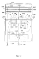
- Fig. 13 is a schematic view showing plural sets of the structure disclosed in FIG. 5 being installed, according to one embodiment of the present invention.
- FIG. 14 is a front view of the embodiment disclosed in FIG. 13 ;
- the building warmed and pumped secondary fluid as reflux by fluid is structured through the fluid kinetic energy and thermal energy of a pressurized thermal energy source, which mainly consists of:
- the same building can be provided with two or more than two sets of thermally actuated and pumped secondary fluid as reflux systems, which includes two or more than two sets of heat exchangers with flowpath (100), fluid actuation device assemblies (20) containing fluid actuation devices (200) and secondary fluid pump sets (202), thermal energy fluid pipelines (105), flowpath structures of secondary fluid (500), flow guide plates of secondary fluid (600) and secondary fluid inlet ports (700), thereby to structure the building warmed and pumped secondary fluid as reflux by fluid, and to form the circulative pumping of partial secondary fluid;
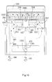
- Fig. 15 is a schematic view showing plural sets of the structure disclosed in FIG. 7 being installed, according to one embodiment of the present invention.
- FIG. 16 is a front view of the embodiment disclosed in FIG. 15 ;
- the building warmed and pumped secondary fluid as reflux by fluid is structured through the fluid kinetic energy and thermal energy of a pressurized thermal energy source, which mainly consists of:
- the same building can be provided with two or more than two sets of thermally actuated and pumped secondary fluid as reflux systems, which includes two or more than two sets of heat exchangers with flowpath (100), fluid actuation device assemblies (20) containing fluid actuation devices (200) and secondary fluid pump sets (202), thermal energy fluid pipelines (105), flowpath structures of secondary fluid (500), flow guide plates of secondary fluid (600) and secondary fluid inlet ports (700), thereby to structure the building warmed and pumped secondary fluid as reflux by fluid, and to form the circulative pumping of partial secondary fluid;
- the temperature differentiation body installed in the temperature differentiation space includes gaseous or liquid fluid, or a solid member disposed in the mentioned gaseous or liquid fluid;
- thermal energy fluid includes gaseous or liquid thermal energy fluid
- the building warmed and pumped secondary fluid as reflux by fluid includes to be applied in the liquid secondary fluid in a tubular or pool-shaped or tank-shaped building, or a lake, or river, or ocean, wherein the thermal energy is transmitted to the secondary fluid serving as the temperature differentiation body through inputting the gaseous or liquid thermal energy fluid;
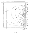
- FIG. 17 is a schematic view showing the present invention being applied in the secondary fluid in a tubular or pool-shaped or tank-shaped semi-opened building, or a lake, or river, or ocean, and the heat exchanger having flowpath (100) being installed in the flowpath structure of secondary fluid (500) and close to the fluid actuation device assembly (20).
- FIG. 18 is a front cross sectional view of FIG. 17 taken along an A-A line.
- the building warmed and pumped secondary fluid as reflux by fluid is structured through the fluid kinetic energy and thermal energy of a pressurized thermal energy source, which mainly consists of:
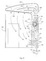
- FIG. 19 is a schematic view showing the present invention being applied in the secondary fluid in a tubular, or spherical, or tank-shaped, or storage room, or cabinet-like sealed building, and the heat exchanger having flowpath (100) being installed in the flowpath structure of secondary fluid (500) and close to the fluid actuation device assembly (20).
- FIG. 20 is a front cross sectional view of FIG. 19 taken along a B-B line.
- the building warmed and pumped secondary fluid as reflux by fluid is structured through the fluid kinetic energy and thermal energy of a pressurized thermal energy source, which mainly consists of:
- the heat exchanger having flowpath (100) and the fluid actuation device (200) driven by thermal energy fluid can be installed by one of the following means according to actual needs, including:
- FIG. 21 is a lateral view showing the embodiment disclosed in FIG. 1 not being installed with the heat exchanger having flowpath (100), and the fluid actuation device (200) being provided to drive the secondary fluid pump set (202) to pump the secondary fluid from the temperature differentiation body space to the internal space of the semi-opened building (300), according to the present invention.
- FIG. 22 is a front view of the embodiment disclosed in FIG. 21 .
- FIG. 21 and FIG. 22 it mainly consists of:
- FIG. 23 is a lateral view showing the embodiment disclosed in FIG. 1 not being installed with the heat exchanger having flowpath (100), and the fluid actuation device (200) being provided to drive the secondary fluid pump set (202) to pump the secondary fluid from the temperature differentiation body space to the internal space of the closed type building (400), according to the present invention.
- FIG. 24 is a front view of the embodiment disclosed in FIG. 23 .
- FIG. 23 and FIG. 24 it mainly consists of:
- the source of the pressurized thermal energy fluid is configured by one or more than one of the followings, including:
- FIG. 27 is a schematic view showing the thermal energy fluid pump (1201) pumping the thermal energy fluid to pass through the fluid pipeline for transmitting natural thermal energy (1100) installed in the natural thermal energy body (1101) for being heated or cooled then pumped out, so as to configure the thermal energy fluid loop, according to the present invention
- the driving means of the fluid actuation device (200) to the secondary fluid pump set (202) includes utilizing the rotation shat (201) inputting the rotary kinetic energy to the input shaft of magnetic non-contact insulation type transmission device (220) of the magnetic non-contact insulation type transmission device (210), then the output shaft of magnetic non-contact insulation type transmission device (221) of the magnetic non-contact insulation type transmission device (210) further driving the secondary fluid pump set (202), wherein the magnetic non-contact insulation type transmission device (210) is equipped with the input shaft of magnetic non-contact insulation type transmission device (220) for driving a passive rotation part of magnetic coupling member (211) of the magnetic non-contact insulation type transmission device (210), and then through a non-magnetic conductive insulation layer to drive an active rotation part of magnetic coupling member (212) of the magnetic non-contact insulation type transmission device (210), and though the passive side with permanent magnet to drive the passive rotation part of magnetic coupling member (211), thereby driving the secondary fluid
- FIG. 28 is a schematic structural view showing a conventional magnetic non-contact insulation type transmission device (210).
- the matching applications of the thermal energy fluid and secondary fluid include one or more than one of the followings:
Landscapes
- Engineering & Computer Science (AREA)
- Mechanical Engineering (AREA)
- General Engineering & Computer Science (AREA)
- Chemical & Material Sciences (AREA)
- Combustion & Propulsion (AREA)
- Physics & Mathematics (AREA)
- Thermal Sciences (AREA)
- Other Air-Conditioning Systems (AREA)
- Instantaneous Water Boilers, Portable Hot-Water Supply Apparatuses, And Control Of Portable Hot-Water Supply Apparatuses (AREA)
- Machine Tool Units (AREA)
- Heat-Exchange Devices With Radiators And Conduit Assemblies (AREA)
- Wind Motors (AREA)
Applications Claiming Priority (2)
| Application Number | Priority Date | Filing Date | Title |
|---|---|---|---|
| US201113213209A | 2011-08-19 | 2011-08-19 | |
| US13/215,266 US9109806B2 (en) | 2011-08-19 | 2011-08-23 | Heating/cooling system that utilizes secondary fluid pumped through a heat exchanger by the pressure of a thermal exchange fluid |
Publications (3)
| Publication Number | Publication Date |
|---|---|
| EP2559950A2 true EP2559950A2 (de) | 2013-02-20 |
| EP2559950A3 EP2559950A3 (de) | 2018-04-04 |
| EP2559950B1 EP2559950B1 (de) | 2022-12-21 |
Family
ID=46724258
Family Applications (1)
| Application Number | Title | Priority Date | Filing Date |
|---|---|---|---|
| EP12180890.1A Active EP2559950B1 (de) | 2011-08-19 | 2012-08-17 | Gebäude-Heiz-Kühl-System mit gepumpter Sekundärflüssigkeit |
Country Status (6)
| Country | Link |
|---|---|
| US (1) | US9109806B2 (de) |
| EP (1) | EP2559950B1 (de) |
| JP (1) | JP6210660B2 (de) |
| CN (2) | CN202853012U (de) |
| AU (1) | AU2012216289B2 (de) |
| TW (2) | TWM463289U (de) |
Cited By (2)
| Publication number | Priority date | Publication date | Assignee | Title |
|---|---|---|---|---|
| GB2525876A (en) * | 2014-05-06 | 2015-11-11 | Francis Gateley | Fan Radiator G M |
| CN114502894A (zh) * | 2019-10-07 | 2022-05-13 | 三菱电机株式会社 | 空气调节机的控制装置、空气调节机、空气调节机的控制方法以及程序 |
Families Citing this family (2)
| Publication number | Priority date | Publication date | Assignee | Title |
|---|---|---|---|---|
| US9109806B2 (en) * | 2011-08-19 | 2015-08-18 | Tai-Her Yang | Heating/cooling system that utilizes secondary fluid pumped through a heat exchanger by the pressure of a thermal exchange fluid |
| CN115127135B (zh) * | 2022-06-20 | 2023-08-08 | 上海巴拿拿科技有限公司 | 一种厂房余热风冷除尘装置 |
Family Cites Families (79)
| Publication number | Priority date | Publication date | Assignee | Title |
|---|---|---|---|---|
| US795761A (en) * | 1901-02-25 | 1905-07-25 | Fulton Co | Atmospheric pressure and temperature motor. |
| US1826950A (en) * | 1928-01-18 | 1931-10-13 | John Wood Mfg Co | Heat exchange apparatus |
| US2649082A (en) * | 1950-06-03 | 1953-08-18 | Engineering Controls Inc | Engine cooling system utilizing waste heat |
| JPS4919813Y1 (de) * | 1968-12-28 | 1974-05-27 | ||
| US3736744A (en) * | 1970-10-13 | 1973-06-05 | W Bailey | Propellants from earth{40 s heats |
| ES402013A1 (es) * | 1971-04-24 | 1975-03-01 | Zanussi A Spa Industrie | Aparato para el acondicionamiento de aire en habitaciones. |
| GB1423350A (en) * | 1972-05-12 | 1976-02-04 | Cooling Dev Ltd | Gas-moving devices |
| US3822554A (en) * | 1972-06-26 | 1974-07-09 | F Kelly | Heat engine |
| US3846987A (en) * | 1973-10-16 | 1974-11-12 | G Baldwin | Rotary fluid motor |
| US3972195A (en) * | 1973-12-14 | 1976-08-03 | Biphase Engines, Inc. | Two-phase engine |
| US3908381A (en) * | 1974-11-20 | 1975-09-30 | Sperry Rand Corp | Geothermal energy conversion system for maximum energy extraction |
| US3953971A (en) * | 1975-01-02 | 1976-05-04 | Parker Sidney A | Power generation arrangement |
| US3952723A (en) * | 1975-02-14 | 1976-04-27 | Browning Engineering Corporation | Windmills |
| US3989189A (en) * | 1975-04-16 | 1976-11-02 | Shimadzu Seisakusho Ltd. | Heating system |
| NZ181445A (en) * | 1975-07-25 | 1978-11-13 | G Blake | Plant groving containers mounted on water powered rotable support |
| US4112687A (en) * | 1975-09-16 | 1978-09-12 | William Paul Dixon | Power source for subsea oil wells |
| US4036017A (en) * | 1976-01-19 | 1977-07-19 | Israel Siegel | Low pressure engine |
| US4041705A (en) * | 1976-04-07 | 1977-08-16 | Israel Siegel | Low temperature engine |
| US4135366A (en) * | 1976-08-02 | 1979-01-23 | Israel Siegel | Valveless differential temperature engine |
| US4059959A (en) * | 1976-11-05 | 1977-11-29 | Sperry Rand Corporation | Geothermal energy processing system with improved heat rejection |
| US4077220A (en) * | 1976-11-09 | 1978-03-07 | Sperry Rand Corporation | Gravity head geothermal energy conversion system |
| US4122675A (en) * | 1977-03-17 | 1978-10-31 | Jack Polyak | Solar heat supplemented convection air stack with turbine blades |
| US4209982A (en) * | 1977-04-07 | 1980-07-01 | Arthur W. Fisher, III | Low temperature fluid energy conversion system |
| US4095429A (en) * | 1977-05-05 | 1978-06-20 | Morey Robert E | Solar gravity engine |
| US4114809A (en) * | 1977-06-09 | 1978-09-19 | Sampson Arthur R | Wind powered hydraulic heating system |
| US4117696A (en) * | 1977-07-05 | 1978-10-03 | Battelle Development Corporation | Heat pump |
| US4197715A (en) * | 1977-07-05 | 1980-04-15 | Battelle Development Corporation | Heat pump |
| US4324983A (en) * | 1977-09-15 | 1982-04-13 | Humiston Gerald F | Binary vapor cycle method of electrical power generation |
| US4143522A (en) * | 1977-09-30 | 1979-03-13 | World Energy Systems | Windmill operated system |
| US4142367A (en) * | 1977-10-17 | 1979-03-06 | Eleanor A. Guisti Dondero | Domestic water pressure-flow powered generator system |
| US4307573A (en) * | 1978-01-11 | 1981-12-29 | King William L | Thermal-cycle engine |
| US4187686A (en) * | 1978-01-16 | 1980-02-12 | Pommier Lorenzo A | Power generator utilizing elevation-temperature differential |
| US4181468A (en) * | 1978-03-09 | 1980-01-01 | Sperry Rand Corporation | Geothermal energy pump monitor and telemetric system |
| US4201060A (en) * | 1978-08-24 | 1980-05-06 | Union Oil Company Of California | Geothermal power plant |
| US4260902A (en) * | 1978-11-28 | 1981-04-07 | Crider William A | Fluid-driven rotary engine |
| US4220003A (en) * | 1979-03-30 | 1980-09-02 | Kiyoshi Doi | Apparatus for generating rotational power |
| US4254626A (en) * | 1979-08-14 | 1981-03-10 | Sea Solar Power | Deaerating system for sea thermal power plants |
| US4299198A (en) * | 1979-09-17 | 1981-11-10 | Woodhull William M | Wind power conversion and control system |
| US4370859A (en) * | 1979-11-26 | 1983-02-01 | Lucien Y. Bronicki | Method of and means for lifting water and generating power therefrom |
| US4342196A (en) * | 1980-07-22 | 1982-08-03 | Yeh Hsu Chieh | Method and apparatus for generating power and irrigating plants with solar energy and earth heat |
| US4423599A (en) * | 1980-08-01 | 1984-01-03 | Veale Charles C | Solar energy utilization apparatus and method |
| US4328673A (en) * | 1980-08-25 | 1982-05-11 | Sperry Corporation | Geothermal pump dual cycle system |
| US4448237A (en) * | 1980-11-17 | 1984-05-15 | William Riley | System for efficiently exchanging heat with ground water in an aquifer |
| US4637209A (en) * | 1981-05-26 | 1987-01-20 | Clark Garry E | Fluid driven power plant |
| US4455834A (en) * | 1981-09-25 | 1984-06-26 | Earle John L | Windmill power apparatus and method |
| US4742682A (en) * | 1982-02-18 | 1988-05-10 | Geophysical Engineering Co. | Energy-saving, direct-contact, parallel-flow heat exchanger |
| JPS6144153U (ja) * | 1984-08-24 | 1986-03-24 | 住友軽金属工業株式会社 | 温泉熱利用熱交換装置 |
| US4588424A (en) * | 1984-10-16 | 1986-05-13 | Heath Rodney T | Fluid pumping system |
| US4607169A (en) * | 1985-01-03 | 1986-08-19 | Donnelly Jr Joseph R | Artesian well generated power system |
| JPS61145217U (de) * | 1985-02-28 | 1986-09-08 | ||
| JPH0439971Y2 (de) * | 1986-06-16 | 1992-09-18 | ||
| US5117635A (en) * | 1990-08-06 | 1992-06-02 | Westinghouse Electric Corp. | High power density propulsion/power system for underwater applications |
| US5226593A (en) * | 1992-01-10 | 1993-07-13 | Beryozkin Vladimir L | Method and means of heating space areas and objects |
| CN2114112U (zh) * | 1992-02-12 | 1992-08-26 | 开鲁县粮食局 | 双向空气对流机 |
| US5488828A (en) * | 1993-05-14 | 1996-02-06 | Brossard; Pierre | Energy generating apparatus |
| US5685147A (en) * | 1995-06-12 | 1997-11-11 | Brassea; Angel | Buoyancy and thermal differentials energy generator |
| DE19525945C2 (de) * | 1995-07-18 | 2000-08-17 | Joachim Griepentrog | Verfahren und Vorrichtung zur Erzeugung behaglicher Raumluftzustände |
| US5709201A (en) * | 1995-10-03 | 1998-01-20 | Anser Thermal Technologies, Inc. | Method and apparatus for heating a liquid medium |
| US6594997B2 (en) * | 2001-10-09 | 2003-07-22 | Pat Romanelli | Vapor engines utilizing closed loop fluorocarbon circuit for power generation |
| JP2004085108A (ja) * | 2002-08-28 | 2004-03-18 | Keisuke Kasahara | 熱媒の熱伝導促進方法とその熱媒製品 |
| TWI303305B (en) * | 2003-04-15 | 2008-11-21 | Tai Her Yang | Natural thermo-carrier heat release sytem |
| JP2006017339A (ja) * | 2004-06-30 | 2006-01-19 | Denso Corp | 冷凍サイクル |
| US7340899B1 (en) * | 2004-10-26 | 2008-03-11 | Solar Energy Production Corporation | Solar power generation system |
| US7084521B1 (en) * | 2005-02-17 | 2006-08-01 | Martin Gerald G | Method and apparatus for generating hydro-electric power |
| JP2007255763A (ja) * | 2006-03-22 | 2007-10-04 | Dai-Dan Co Ltd | 送風ユニット |
| JP2007262298A (ja) * | 2006-03-29 | 2007-10-11 | Fujitsu General Ltd | 潤滑油、冷媒回路装置および過冷却度の改善方法 |
| US7870735B2 (en) * | 2007-03-07 | 2011-01-18 | Romanelli Energy Systems, L.L.C. | Closed loop expandable gas circuit for power generation |
| DE102007014274A1 (de) * | 2007-03-16 | 2008-09-25 | Ltg Aktiengesellschaft | Verfahren zum Temperieren von Luft in einem Raum sowie Wandelement zur Raumtemperierung |
| US7877999B2 (en) * | 2007-04-13 | 2011-02-01 | Cool Energy, Inc. | Power generation and space conditioning using a thermodynamic engine driven through environmental heating and cooling |
| CN100430661C (zh) * | 2007-06-22 | 2008-11-05 | 哈尔滨工业大学 | 利用自然风能的热量回收新风换气装置 |
| US7958731B2 (en) * | 2009-01-20 | 2011-06-14 | Sustainx, Inc. | Systems and methods for combined thermal and compressed gas energy conversion systems |
| US20100018672A1 (en) * | 2008-07-22 | 2010-01-28 | Tai-Her Yang | Conducting type inter-piping fluid thermal energy transfer device |
| US20100018679A1 (en) * | 2008-07-22 | 2010-01-28 | Tai-Her Yang | Isothermal method and device using periodic direction-change utility water flow |
| US8215104B2 (en) * | 2008-09-29 | 2012-07-10 | William Riley | Energy from subterranean reservoir fluid |
| CN101965456B (zh) * | 2009-04-15 | 2014-10-29 | 观音能量株式会社 | 太阳能热发电装置 |
| US9163512B2 (en) * | 2009-09-16 | 2015-10-20 | Solar Logic Incorporated | Bladeless turbine |
| US8449726B2 (en) * | 2010-06-30 | 2013-05-28 | Fahad Alawadi | Solar thermal system for the partial desalination of seawater and electrical energy |
| US8459248B2 (en) * | 2010-12-06 | 2013-06-11 | Solarlogic, Llc | Solar fluid heating and cooling system |
| US9109806B2 (en) * | 2011-08-19 | 2015-08-18 | Tai-Her Yang | Heating/cooling system that utilizes secondary fluid pumped through a heat exchanger by the pressure of a thermal exchange fluid |
-
2011
- 2011-08-23 US US13/215,266 patent/US9109806B2/en active Active
-
2012
- 2012-08-15 TW TW101215695U patent/TWM463289U/zh unknown
- 2012-08-15 TW TW101129497A patent/TWI618902B/zh active
- 2012-08-16 CN CN2012204076345U patent/CN202853012U/zh not_active Expired - Lifetime
- 2012-08-16 CN CN201210292711.1A patent/CN102954544B/zh active Active
- 2012-08-17 EP EP12180890.1A patent/EP2559950B1/de active Active
- 2012-08-17 AU AU2012216289A patent/AU2012216289B2/en active Active
- 2012-08-20 JP JP2012181498A patent/JP6210660B2/ja active Active
Non-Patent Citations (1)
| Title |
|---|
| None |
Cited By (2)
| Publication number | Priority date | Publication date | Assignee | Title |
|---|---|---|---|---|
| GB2525876A (en) * | 2014-05-06 | 2015-11-11 | Francis Gateley | Fan Radiator G M |
| CN114502894A (zh) * | 2019-10-07 | 2022-05-13 | 三菱电机株式会社 | 空气调节机的控制装置、空气调节机、空气调节机的控制方法以及程序 |
Also Published As
| Publication number | Publication date |
|---|---|
| CN202853012U (zh) | 2013-04-03 |
| CN102954544B (zh) | 2017-03-01 |
| TW201319484A (zh) | 2013-05-16 |
| TWM463289U (zh) | 2013-10-11 |
| AU2012216289B2 (en) | 2016-12-22 |
| EP2559950A3 (de) | 2018-04-04 |
| CN102954544A (zh) | 2013-03-06 |
| JP6210660B2 (ja) | 2017-10-11 |
| JP2013044521A (ja) | 2013-03-04 |
| TWI618902B (zh) | 2018-03-21 |
| AU2012216289A1 (en) | 2013-03-07 |
| EP2559950B1 (de) | 2022-12-21 |
| US9109806B2 (en) | 2015-08-18 |
| US20130043011A1 (en) | 2013-02-21 |
Similar Documents
| Publication | Publication Date | Title |
|---|---|---|
| US8607854B2 (en) | Fluid heat transfer device having plural counter flow circuits with periodic flow direction change therethrough | |
| CN102761201A (zh) | 用于电机的冷却设置 | |
| EP2559950B1 (de) | Gebäude-Heiz-Kühl-System mit gepumpter Sekundärflüssigkeit | |
| Tang et al. | Experimental investigation on thermal management performance of an integrated heat sink with a piezoelectric micropump | |
| CN103368468B (zh) | 磁热发电系统 | |
| US9759456B2 (en) | Combined heat and power heat pump | |
| US20120125575A1 (en) | Cold/heat discharge with inner fluid to actuate the external fluid pump | |
| CN107002712A (zh) | 用于液压机组的冷却装置和冷却装置的使用 | |
| JP4410283B2 (ja) | 水冷装置 | |
| CN102450954B (zh) | 热电式饮用装置及热电式热泵 | |
| CN113629311B (zh) | 换热器、车载电池热管理系统、车辆及充电站 | |
| US9115935B2 (en) | Single flow circuit heat absorbing/release device for periodic positive and reverse directional pumping | |
| ES2353703T3 (es) | Sistema intercambiador de calor. | |
| JP2012023258A (ja) | 温度差発電装置及び温度差発電方法 | |
| CN223681399U (zh) | 一种散热系统 | |
| CN220776362U (zh) | 一种散热器总成及工程机械 | |
| CN223758634U (zh) | 数据中心液冷空调系统 | |
| CN219534654U (zh) | 一种紧凑型电池液冷机组 | |
| CN117476576B (zh) | 一种芯片冷却系统及控制方法 | |
| CN111076448A (zh) | 一种热水利用装置及冷冻水系统 | |
| CN201187958Y (zh) | 一种空压机余热自动采集换热器 | |
| CN101382403B (zh) | 模块化芯体冷却系统 | |
| CN117104482A (zh) | 推进器及水域可移动设备 | |
| WO2009133330A1 (en) | Pump apparatus | |
| CN202444377U (zh) | 风力发电机 |
Legal Events
| Date | Code | Title | Description |
|---|---|---|---|
| PUAI | Public reference made under article 153(3) epc to a published international application that has entered the european phase |
Free format text: ORIGINAL CODE: 0009012 |
|
| AK | Designated contracting states |
Kind code of ref document: A2 Designated state(s): AL AT BE BG CH CY CZ DE DK EE ES FI FR GB GR HR HU IE IS IT LI LT LU LV MC MK MT NL NO PL PT RO RS SE SI SK SM TR |
|
| AX | Request for extension of the european patent |
Extension state: BA ME |
|
| PUAL | Search report despatched |
Free format text: ORIGINAL CODE: 0009013 |
|
| AK | Designated contracting states |
Kind code of ref document: A3 Designated state(s): AL AT BE BG CH CY CZ DE DK EE ES FI FR GB GR HR HU IE IS IT LI LT LU LV MC MK MT NL NO PL PT RO RS SE SI SK SM TR |
|
| AX | Request for extension of the european patent |
Extension state: BA ME |
|
| RIC1 | Information provided on ipc code assigned before grant |
Ipc: F24F 1/01 20110101ALI20180227BHEP Ipc: F28F 9/02 20060101ALI20180227BHEP Ipc: F24D 19/00 20060101ALI20180227BHEP Ipc: F24D 5/02 20060101ALI20180227BHEP Ipc: F28D 1/02 20060101ALI20180227BHEP Ipc: F24F 13/30 20060101ALI20180227BHEP Ipc: F24F 1/00 20110101AFI20180227BHEP |
|
| STAA | Information on the status of an ep patent application or granted ep patent |
Free format text: STATUS: THE APPLICATION HAS BEEN PUBLISHED |
|
| STAA | Information on the status of an ep patent application or granted ep patent |
Free format text: STATUS: REQUEST FOR EXAMINATION WAS MADE |
|
| 17P | Request for examination filed |
Effective date: 20190116 |
|
| RBV | Designated contracting states (corrected) |
Designated state(s): AL AT BE BG CH CY CZ DE DK EE ES FI FR GB GR HR HU IE IS IT LI LT LU LV MC MK MT NL NO PL PT RO RS SE SI SK SM TR |
|
| STAA | Information on the status of an ep patent application or granted ep patent |
Free format text: STATUS: EXAMINATION IS IN PROGRESS |
|
| 17Q | First examination report despatched |
Effective date: 20191002 |
|
| GRAP | Despatch of communication of intention to grant a patent |
Free format text: ORIGINAL CODE: EPIDOSNIGR1 |
|
| STAA | Information on the status of an ep patent application or granted ep patent |
Free format text: STATUS: GRANT OF PATENT IS INTENDED |
|
| INTG | Intention to grant announced |
Effective date: 20220712 |
|
| GRAS | Grant fee paid |
Free format text: ORIGINAL CODE: EPIDOSNIGR3 |
|
| GRAA | (expected) grant |
Free format text: ORIGINAL CODE: 0009210 |
|
| STAA | Information on the status of an ep patent application or granted ep patent |
Free format text: STATUS: THE PATENT HAS BEEN GRANTED |
|
| AK | Designated contracting states |
Kind code of ref document: B1 Designated state(s): AL AT BE BG CH CY CZ DE DK EE ES FI FR GB GR HR HU IE IS IT LI LT LU LV MC MK MT NL NO PL PT RO RS SE SI SK SM TR |
|
| REG | Reference to a national code |
Ref country code: GB Ref legal event code: FG4D |
|
| REG | Reference to a national code |
Ref country code: DE Ref legal event code: R096 Ref document number: 602012079131 Country of ref document: DE |
|
| REG | Reference to a national code |
Ref country code: CH Ref legal event code: EP |
|
| REG | Reference to a national code |
Ref country code: AT Ref legal event code: REF Ref document number: 1539271 Country of ref document: AT Kind code of ref document: T Effective date: 20230115 |
|
| REG | Reference to a national code |
Ref country code: IE Ref legal event code: FG4D |
|
| REG | Reference to a national code |
Ref country code: NL Ref legal event code: FP |
|
| REG | Reference to a national code |
Ref country code: LT Ref legal event code: MG9D |
|
| PG25 | Lapsed in a contracting state [announced via postgrant information from national office to epo] |
Ref country code: SE Free format text: LAPSE BECAUSE OF FAILURE TO SUBMIT A TRANSLATION OF THE DESCRIPTION OR TO PAY THE FEE WITHIN THE PRESCRIBED TIME-LIMIT Effective date: 20221221 Ref country code: NO Free format text: LAPSE BECAUSE OF FAILURE TO SUBMIT A TRANSLATION OF THE DESCRIPTION OR TO PAY THE FEE WITHIN THE PRESCRIBED TIME-LIMIT Effective date: 20230321 Ref country code: LT Free format text: LAPSE BECAUSE OF FAILURE TO SUBMIT A TRANSLATION OF THE DESCRIPTION OR TO PAY THE FEE WITHIN THE PRESCRIBED TIME-LIMIT Effective date: 20221221 Ref country code: FI Free format text: LAPSE BECAUSE OF FAILURE TO SUBMIT A TRANSLATION OF THE DESCRIPTION OR TO PAY THE FEE WITHIN THE PRESCRIBED TIME-LIMIT Effective date: 20221221 |
|
| REG | Reference to a national code |
Ref country code: AT Ref legal event code: MK05 Ref document number: 1539271 Country of ref document: AT Kind code of ref document: T Effective date: 20221221 |
|
| PG25 | Lapsed in a contracting state [announced via postgrant information from national office to epo] |
Ref country code: RS Free format text: LAPSE BECAUSE OF FAILURE TO SUBMIT A TRANSLATION OF THE DESCRIPTION OR TO PAY THE FEE WITHIN THE PRESCRIBED TIME-LIMIT Effective date: 20221221 Ref country code: LV Free format text: LAPSE BECAUSE OF FAILURE TO SUBMIT A TRANSLATION OF THE DESCRIPTION OR TO PAY THE FEE WITHIN THE PRESCRIBED TIME-LIMIT Effective date: 20221221 Ref country code: HR Free format text: LAPSE BECAUSE OF FAILURE TO SUBMIT A TRANSLATION OF THE DESCRIPTION OR TO PAY THE FEE WITHIN THE PRESCRIBED TIME-LIMIT Effective date: 20221221 Ref country code: GR Free format text: LAPSE BECAUSE OF FAILURE TO SUBMIT A TRANSLATION OF THE DESCRIPTION OR TO PAY THE FEE WITHIN THE PRESCRIBED TIME-LIMIT Effective date: 20230322 |
|
| PG25 | Lapsed in a contracting state [announced via postgrant information from national office to epo] |
Ref country code: SM Free format text: LAPSE BECAUSE OF FAILURE TO SUBMIT A TRANSLATION OF THE DESCRIPTION OR TO PAY THE FEE WITHIN THE PRESCRIBED TIME-LIMIT Effective date: 20221221 Ref country code: RO Free format text: LAPSE BECAUSE OF FAILURE TO SUBMIT A TRANSLATION OF THE DESCRIPTION OR TO PAY THE FEE WITHIN THE PRESCRIBED TIME-LIMIT Effective date: 20221221 Ref country code: PT Free format text: LAPSE BECAUSE OF FAILURE TO SUBMIT A TRANSLATION OF THE DESCRIPTION OR TO PAY THE FEE WITHIN THE PRESCRIBED TIME-LIMIT Effective date: 20230421 Ref country code: ES Free format text: LAPSE BECAUSE OF FAILURE TO SUBMIT A TRANSLATION OF THE DESCRIPTION OR TO PAY THE FEE WITHIN THE PRESCRIBED TIME-LIMIT Effective date: 20221221 Ref country code: EE Free format text: LAPSE BECAUSE OF FAILURE TO SUBMIT A TRANSLATION OF THE DESCRIPTION OR TO PAY THE FEE WITHIN THE PRESCRIBED TIME-LIMIT Effective date: 20221221 Ref country code: CZ Free format text: LAPSE BECAUSE OF FAILURE TO SUBMIT A TRANSLATION OF THE DESCRIPTION OR TO PAY THE FEE WITHIN THE PRESCRIBED TIME-LIMIT Effective date: 20221221 Ref country code: AT Free format text: LAPSE BECAUSE OF FAILURE TO SUBMIT A TRANSLATION OF THE DESCRIPTION OR TO PAY THE FEE WITHIN THE PRESCRIBED TIME-LIMIT Effective date: 20221221 |
|
| PG25 | Lapsed in a contracting state [announced via postgrant information from national office to epo] |
Ref country code: SK Free format text: LAPSE BECAUSE OF FAILURE TO SUBMIT A TRANSLATION OF THE DESCRIPTION OR TO PAY THE FEE WITHIN THE PRESCRIBED TIME-LIMIT Effective date: 20221221 Ref country code: PL Free format text: LAPSE BECAUSE OF FAILURE TO SUBMIT A TRANSLATION OF THE DESCRIPTION OR TO PAY THE FEE WITHIN THE PRESCRIBED TIME-LIMIT Effective date: 20221221 Ref country code: IS Free format text: LAPSE BECAUSE OF FAILURE TO SUBMIT A TRANSLATION OF THE DESCRIPTION OR TO PAY THE FEE WITHIN THE PRESCRIBED TIME-LIMIT Effective date: 20230421 Ref country code: AL Free format text: LAPSE BECAUSE OF FAILURE TO SUBMIT A TRANSLATION OF THE DESCRIPTION OR TO PAY THE FEE WITHIN THE PRESCRIBED TIME-LIMIT Effective date: 20221221 |
|
| REG | Reference to a national code |
Ref country code: DE Ref legal event code: R097 Ref document number: 602012079131 Country of ref document: DE |
|
| PLBE | No opposition filed within time limit |
Free format text: ORIGINAL CODE: 0009261 |
|
| STAA | Information on the status of an ep patent application or granted ep patent |
Free format text: STATUS: NO OPPOSITION FILED WITHIN TIME LIMIT |
|
| PG25 | Lapsed in a contracting state [announced via postgrant information from national office to epo] |
Ref country code: DK Free format text: LAPSE BECAUSE OF FAILURE TO SUBMIT A TRANSLATION OF THE DESCRIPTION OR TO PAY THE FEE WITHIN THE PRESCRIBED TIME-LIMIT Effective date: 20221221 |
|
| PGFP | Annual fee paid to national office [announced via postgrant information from national office to epo] |
Ref country code: CH Payment date: 20230906 Year of fee payment: 12 |
|
| 26N | No opposition filed |
Effective date: 20230922 |
|
| PG25 | Lapsed in a contracting state [announced via postgrant information from national office to epo] |
Ref country code: SI Free format text: LAPSE BECAUSE OF FAILURE TO SUBMIT A TRANSLATION OF THE DESCRIPTION OR TO PAY THE FEE WITHIN THE PRESCRIBED TIME-LIMIT Effective date: 20221221 |
|
| PG25 | Lapsed in a contracting state [announced via postgrant information from national office to epo] |
Ref country code: MC Free format text: LAPSE BECAUSE OF FAILURE TO SUBMIT A TRANSLATION OF THE DESCRIPTION OR TO PAY THE FEE WITHIN THE PRESCRIBED TIME-LIMIT Effective date: 20221221 |
|
| PG25 | Lapsed in a contracting state [announced via postgrant information from national office to epo] |
Ref country code: MC Free format text: LAPSE BECAUSE OF FAILURE TO SUBMIT A TRANSLATION OF THE DESCRIPTION OR TO PAY THE FEE WITHIN THE PRESCRIBED TIME-LIMIT Effective date: 20221221 |
|
| PG25 | Lapsed in a contracting state [announced via postgrant information from national office to epo] |
Ref country code: LU Free format text: LAPSE BECAUSE OF NON-PAYMENT OF DUE FEES Effective date: 20230817 |
|
| PG25 | Lapsed in a contracting state [announced via postgrant information from national office to epo] |
Ref country code: LU Free format text: LAPSE BECAUSE OF NON-PAYMENT OF DUE FEES Effective date: 20230817 |
|
| REG | Reference to a national code |
Ref country code: BE Ref legal event code: MM Effective date: 20230831 |
|
| REG | Reference to a national code |
Ref country code: IE Ref legal event code: MM4A |
|
| PG25 | Lapsed in a contracting state [announced via postgrant information from national office to epo] |
Ref country code: IT Free format text: LAPSE BECAUSE OF FAILURE TO SUBMIT A TRANSLATION OF THE DESCRIPTION OR TO PAY THE FEE WITHIN THE PRESCRIBED TIME-LIMIT Effective date: 20221221 |
|
| PG25 | Lapsed in a contracting state [announced via postgrant information from national office to epo] |
Ref country code: IE Free format text: LAPSE BECAUSE OF NON-PAYMENT OF DUE FEES Effective date: 20230817 |
|
| PG25 | Lapsed in a contracting state [announced via postgrant information from national office to epo] |
Ref country code: IE Free format text: LAPSE BECAUSE OF NON-PAYMENT OF DUE FEES Effective date: 20230817 |
|
| PG25 | Lapsed in a contracting state [announced via postgrant information from national office to epo] |
Ref country code: BE Free format text: LAPSE BECAUSE OF NON-PAYMENT OF DUE FEES Effective date: 20230831 |
|
| PG25 | Lapsed in a contracting state [announced via postgrant information from national office to epo] |
Ref country code: BG Free format text: LAPSE BECAUSE OF FAILURE TO SUBMIT A TRANSLATION OF THE DESCRIPTION OR TO PAY THE FEE WITHIN THE PRESCRIBED TIME-LIMIT Effective date: 20221221 |
|
| PG25 | Lapsed in a contracting state [announced via postgrant information from national office to epo] |
Ref country code: BG Free format text: LAPSE BECAUSE OF FAILURE TO SUBMIT A TRANSLATION OF THE DESCRIPTION OR TO PAY THE FEE WITHIN THE PRESCRIBED TIME-LIMIT Effective date: 20221221 |
|
| REG | Reference to a national code |
Ref country code: CH Ref legal event code: PL |
|
| PG25 | Lapsed in a contracting state [announced via postgrant information from national office to epo] |
Ref country code: CH Free format text: LAPSE BECAUSE OF NON-PAYMENT OF DUE FEES Effective date: 20240831 |
|
| PG25 | Lapsed in a contracting state [announced via postgrant information from national office to epo] |
Ref country code: CY Free format text: LAPSE BECAUSE OF FAILURE TO SUBMIT A TRANSLATION OF THE DESCRIPTION OR TO PAY THE FEE WITHIN THE PRESCRIBED TIME-LIMIT; INVALID AB INITIO Effective date: 20120817 |
|
| PG25 | Lapsed in a contracting state [announced via postgrant information from national office to epo] |
Ref country code: HU Free format text: LAPSE BECAUSE OF FAILURE TO SUBMIT A TRANSLATION OF THE DESCRIPTION OR TO PAY THE FEE WITHIN THE PRESCRIBED TIME-LIMIT; INVALID AB INITIO Effective date: 20120817 |
|
| PGFP | Annual fee paid to national office [announced via postgrant information from national office to epo] |
Ref country code: DE Payment date: 20250919 Year of fee payment: 14 |
|
| PGFP | Annual fee paid to national office [announced via postgrant information from national office to epo] |
Ref country code: NL Payment date: 20250829 Year of fee payment: 14 |
|
| PGFP | Annual fee paid to national office [announced via postgrant information from national office to epo] |
Ref country code: GB Payment date: 20250829 Year of fee payment: 14 |
|
| PGFP | Annual fee paid to national office [announced via postgrant information from national office to epo] |
Ref country code: FR Payment date: 20250829 Year of fee payment: 14 |
|
| PG25 | Lapsed in a contracting state [announced via postgrant information from national office to epo] |
Ref country code: TR Free format text: LAPSE BECAUSE OF FAILURE TO SUBMIT A TRANSLATION OF THE DESCRIPTION OR TO PAY THE FEE WITHIN THE PRESCRIBED TIME-LIMIT Effective date: 20221221 |