EP2558751B1 - Arrangement of a valve in a bore of a duct housing - Google Patents
Arrangement of a valve in a bore of a duct housing Download PDFInfo
- Publication number
- EP2558751B1 EP2558751B1 EP11710758.1A EP11710758A EP2558751B1 EP 2558751 B1 EP2558751 B1 EP 2558751B1 EP 11710758 A EP11710758 A EP 11710758A EP 2558751 B1 EP2558751 B1 EP 2558751B1
- Authority
- EP
- European Patent Office
- Prior art keywords
- valve
- housing
- bore
- surrounding
- arrangement
- Prior art date
- Legal status (The legal status is an assumption and is not a legal conclusion. Google has not performed a legal analysis and makes no representation as to the accuracy of the status listed.)
- Revoked
Links
Images
Classifications
-
- F—MECHANICAL ENGINEERING; LIGHTING; HEATING; WEAPONS; BLASTING
- F16—ENGINEERING ELEMENTS AND UNITS; GENERAL MEASURES FOR PRODUCING AND MAINTAINING EFFECTIVE FUNCTIONING OF MACHINES OR INSTALLATIONS; THERMAL INSULATION IN GENERAL
- F16K—VALVES; TAPS; COCKS; ACTUATING-FLOATS; DEVICES FOR VENTING OR AERATING
- F16K1/00—Lift valves or globe valves, i.e. cut-off apparatus with closure members having at least a component of their opening and closing motion perpendicular to the closing faces
- F16K1/32—Details
- F16K1/34—Cutting-off parts, e.g. valve members, seats
- F16K1/44—Details of seats or valve members of double-seat valves
-
- F—MECHANICAL ENGINEERING; LIGHTING; HEATING; WEAPONS; BLASTING
- F02—COMBUSTION ENGINES; HOT-GAS OR COMBUSTION-PRODUCT ENGINE PLANTS
- F02M—SUPPLYING COMBUSTION ENGINES IN GENERAL WITH COMBUSTIBLE MIXTURES OR CONSTITUENTS THEREOF
- F02M26/00—Engine-pertinent apparatus for adding exhaust gases to combustion-air, main fuel or fuel-air mixture, e.g. by exhaust gas recirculation [EGR] systems
- F02M26/11—Manufacture or assembly of EGR systems; Materials or coatings specially adapted for EGR systems
-
- F—MECHANICAL ENGINEERING; LIGHTING; HEATING; WEAPONS; BLASTING
- F02—COMBUSTION ENGINES; HOT-GAS OR COMBUSTION-PRODUCT ENGINE PLANTS
- F02M—SUPPLYING COMBUSTION ENGINES IN GENERAL WITH COMBUSTIBLE MIXTURES OR CONSTITUENTS THEREOF
- F02M26/00—Engine-pertinent apparatus for adding exhaust gases to combustion-air, main fuel or fuel-air mixture, e.g. by exhaust gas recirculation [EGR] systems
- F02M26/65—Constructional details of EGR valves
- F02M26/66—Lift valves, e.g. poppet valves
- F02M26/69—Lift valves, e.g. poppet valves having two or more valve-closing members
-
- F—MECHANICAL ENGINEERING; LIGHTING; HEATING; WEAPONS; BLASTING
- F02—COMBUSTION ENGINES; HOT-GAS OR COMBUSTION-PRODUCT ENGINE PLANTS
- F02M—SUPPLYING COMBUSTION ENGINES IN GENERAL WITH COMBUSTIBLE MIXTURES OR CONSTITUENTS THEREOF
- F02M26/00—Engine-pertinent apparatus for adding exhaust gases to combustion-air, main fuel or fuel-air mixture, e.g. by exhaust gas recirculation [EGR] systems
- F02M26/65—Constructional details of EGR valves
- F02M26/72—Housings
-
- F—MECHANICAL ENGINEERING; LIGHTING; HEATING; WEAPONS; BLASTING
- F16—ENGINEERING ELEMENTS AND UNITS; GENERAL MEASURES FOR PRODUCING AND MAINTAINING EFFECTIVE FUNCTIONING OF MACHINES OR INSTALLATIONS; THERMAL INSULATION IN GENERAL
- F16K—VALVES; TAPS; COCKS; ACTUATING-FLOATS; DEVICES FOR VENTING OR AERATING
- F16K11/00—Multiple-way valves, e.g. mixing valves; Pipe fittings incorporating such valves
- F16K11/02—Multiple-way valves, e.g. mixing valves; Pipe fittings incorporating such valves with all movable sealing faces moving as one unit
- F16K11/04—Multiple-way valves, e.g. mixing valves; Pipe fittings incorporating such valves with all movable sealing faces moving as one unit comprising only lift valves
Definitions
- the invention relates to an arrangement of a valve in a bore of a channel housing with a one-piece valve housing in which an inlet and at least one outlet are formed and which is inserted into the bore of the channel housing, wherein in the valve housing a translationally movable valve rod is arranged, on which at least arranged with a valve seat corresponding valve closing body.
- valves are used for example in internal combustion engines as exhaust gas recirculation valves in exhaust gas recirculation channels.
- This embodiment as a pluggable valve with a housing, which already forms parts of one or more channels, has the advantage that such a valve can be completely pre-assembled and shipped and only then installed in the channel housing.
- Such a valve is inserted into the channel housing from an open side of a bore in the channel housing and fastened to the channel housing, for example by means of screws.
- an exhaust gas recirculation valve which is designed as a plug-in valve, wherein the plug valve has an exhaust gas inlet and two exhaust gas outlets.
- the connection between the input and the output can be regulated by means of two valve members arranged on a common actuating rod be lowered by these on a valve seat or lifted off this.
- the inlet is arranged between the two valve seats and thus also between the two exhaust outlets.
- the arrangement of the valve takes place in a bore of the surrounding channel housing.
- the valve housing and the channel housing each have a continuous uniform diameter. These two diameters are usually designed as a continuous fit of fit, whereby a sufficient tightness to the outside and between the channels is usually ensured.
- problems arise with such an arrangement in the installation and removal of the valve housing In particular, with repeated installation and removal, grooves are formed on the mutually facing housing walls, which leads to a growing leakage.
- the outer diameter of the plug valve is slightly smaller than the bore diameter of the channel housing, wherein the channel housing and the valve housing having a corresponding shoulder, which forms a bearing surface.
- the channel housing and the valve housing having a corresponding shoulder, which forms a bearing surface.
- On this bearing surface and on the mounting surface of the plug valve on the outer wall of the channel housing each bead seals are placed, which are clamped between the two housing parts and thus lead to a radial seal.
- additional shoulders and seals would be required. The seals could not be preassembled so that the valve supplier can not guarantee correct and tight installation in the housing.
- a separate valve seat is formed in the surrounding channel housing.
- the housing of the plug valve is stepped and each has a smaller outer diameter than the inner diameter of the surrounding channel housing.
- a seal takes place in accordance with n axial direction.
- the valve seat is formed on the valve housing. A seal to the outside and between the housing parts takes place in each case via sealing rings.
- valve assembly in which the valve housing is cylindrical and is inserted into a stepped bore having annular recesses, whereby outside of the valve seats surrounding areas a distance from the outer wall of the valve housing is provided.
- the invention relates to an arrangement of a valve in a bore of a channel housing with a valve housing in which an inlet and at least one outlet are formed and which is inserted into the bore of the channel housing, wherein in the valve housing, a translationally movable valve rod is arranged, on which at least one arranged with a valve seat corresponding valve closing body.
- the invention solves the problem in that the bore is step-shaped, wherein the bore diameter decreases in the insertion of the valve housing and the outer diameter of the valve housing is stepped such that a fit to the respective bore diameter is formed in the at least one valve seat surrounding areas, while the Other areas have an outer diameter which is smaller than the radially surrounding bore diameter and smaller than the outer diameter of the adjacent, the at least one valve seat surrounding areas, so that there is a gap between the valve housing and the surrounding channel housing in these areas, a good seal reached.
- such a valve with relatively little effort can be mounted, since the sliding surfaces of the two housings are significantly reduced to each other.
- the mechanical loading of the two surfaces sliding along one another also decreases, so that the abrasion is significantly reduced with repeated assembly and disassembly and thus largely unchanged leakage rates are achieved.
- the valve has two valve closing bodies on a valve rod, by means of which two through-flow passages surrounded by valve seats can be regulated, which lead to two outlets on the valve housing, the inlet being arranged between the two outlets.
- two valve closing bodies on a valve rod by means of which two through-flow passages surrounded by valve seats can be regulated, which lead to two outlets on the valve housing, the inlet being arranged between the two outlets.
- both have the valve seats surrounding areas of the valve housing to an outer diameter which substantially corresponds to the associated bore diameter of the channel housing. Over these contact surfaces is thus the Seal realized between the two housings. At the same time, the seal on the seal-relevant areas around the inlet and thus around the area of higher pressure is meaningfully limited. It is ensured both a seal to the environment and with respect to the outlets.
- the channel housing has three different bore diameters, two of which correspond to the two areas surrounding the valve seats, which are arranged axially to the two sides of the inlet.
- a simple insertion of the valve into the bore is possible, since the two fits are realized in different diameters and thus contact of the housing is given only in the last insertion area.
- the bore paragraphs viewed in the insertion direction of the valve housing are each formed directly in front of the corresponding fit fits. This shortens the axial contact length when inserting the valve to a minimum, so that the wear of the surfaces during assembly and disassembly is significantly reduced.
- the valve housing preferably has a chamfer or rounding at the end which projects in the insertion direction.
- valve housing between the two valve seats on a region in which the outer diameter of the valve housing is smaller than the surrounding bore diameter so that there is a gap between the valve housing and the surrounding channel housing in this area.
- this area is also one of the gradations of the housing bore.
- valve housing preferably has a region between the insertion opening of the channel housing and the valve seat arranged closer to the insertion opening, in which the outer diameter of the valve housing is smaller than the surrounding bore diameter, so that there is a gap between the valve housing and the surrounding channel housing in this area , In this area is also a gradation of the housing bore. This also leads to shortened sliding surfaces during assembly and disassembly of the valve.
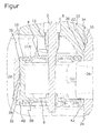
- the figure shows a side view of a section of a valve in a bore of a channel housing in a sectional view.
- the illustrated valve consists of a valve rod 2, which is movable in translation via an actuator (not shown), on which two valve closing bodies 4, 6 are at least axially fixed.
- the valve rod 2 is axially guided in a slide bushing 8, which is mounted in a valve housing 10.
- the valve rod 2 is in her to the slide bushing subsequent area surrounded by a shielding plate 11, which prevents penetration of gas into the sliding bush 10 as far as possible.
- the valve housing 10 has a radial inlet 12 and a radial outlet 14 and an axial outlet 16, wherein the inlet 12 is arranged axially between the two outlets 14, 16.
- Between the inlet 12 and the outlets 14, 16 is in each case an adjustable flow cross-section, each surrounded by a valve seat 18, 20, which in turn cooperates with one of the valve closing body 4, 6 such that upon movement of the valve rod 2 and thus the Valve-closing body 4, 6, the two flow cross-sections are reduced by synchronously lowering the valve closing body 4, 6 in the direction of the valve seats 18, 20 or increased by synchronous removal of the valve seats 18, 20.
- the valve seats 18, 20 are fastened in the valve housing 10.
- the valve housing 10 is disposed in a bore 22 of a channel housing 24, wherein leaks between the two housings 10, 24 must be avoided.
- the channel housing 24 has a first channel section 26, which corresponds to the inlet 12 of the valve housing 10, and a secondary channel section 28 which communicates with the channels 14, 16.
- the bore 22 has a first bore shoulder 30 and a second bore shoulder 32, at which the bore diameter is reduced stepwise in the insertion direction of the valve from the insertion opening.
- the insertion direction corresponds to the direction of movement of the valve closing body for releasing the flow cross sections.
- the valve is inserted in the direction of the axial outlet 16 of the insertion opening, not shown, of the channel housing 24 into the bore 22.
- the valve housing has five successively arranged regions of different outer diameter in the axial direction.
- a first region 34 When mounted, in the insertion direction of the valve, a first region 34 has an outer diameter which is smaller than the bore diameter radially surrounding this region 34, so that no contact occurs between the walls.
- the first bore shoulder 30 Radially out of this region 34, the first bore shoulder 30 is arranged, which is in the immediate vicinity of a second region 36 adjoining the first region 34, which has a larger outer diameter than the first region 34.
- This region 36 has a fit fit to the bore 22 and extends axially with respect to the valve seat 18 on both sides.
- a third region 38 adjoining the second region 36 again has a smaller outer diameter which is also smaller than the smallest bore diameter beyond the second bore paragraph 32 and also extends beyond it, a gap between the housings 10, 24.
- a region 40 of the valve housing 10 which adjoins the area 38 in an axial direction in turn has a substantially identical outside diameter as the surrounding bore 22.
- the diameter of the region 40 is smaller than that of the second region 36, since it is located beyond the bore shoulder 32 and thus has an interference fit to the smallest bore diameter.
- This area 40 in turn surrounds the valve seat 20, so that the inlet 12 is surrounded on both axial sides of the fit fits.
- a fifth region in the form of a chamfer 42 which tapers in the direction of the outlet 16.
- valve housing 10 can first be easily inserted through the chamfer 42 in the bore.
- a first resistance during insertion in the axial direction is formed only when the fourth region 40 is pushed over the shoulder 32 of the bore 22.
- This area 40 then slides along the surrounding bore wall.
- a second fit fit is achieved only when the second portion 36 is pushed over the bore 30 paragraph.
- the Fügein or sliding surface lengths are significantly shortened by this design.
- the seal is made by the fit between the bore diameter and the second region 36 and the fourth region 40 of the valve housing 10.
- the fourth region 40 prevents leakage from the inlet 26 to the outlet 16 while the second region 36 a leakage flow from the inlet 26 to the outlet 14th prevented.
- a seal from the radial outlet 14 to the environment is not required depending on the pressure conditions or can be done via the attachment of the plug valve to the housing.
- the formation of a further gradation of the housing in the sense of the application would be conceivable.
Description
Die Erfindung betrifft eine Anordnung eines Ventils in einer Bohrung eines Kanalgehäuses mit einem einstückigen Ventilgehäuse, in dem ein Eintritt und zumindest ein Austritt ausgebildet sind und welches in die Bohrung des Kanalgehäuses eingesteckt ist, wobei im Ventilgehäuse eine translatorisch bewegbare Ventilstange angeordnet ist, auf welcher zumindest ein mit einem Ventilsitz korrespondierender Ventilschließkörper angeordnet ist.The invention relates to an arrangement of a valve in a bore of a channel housing with a one-piece valve housing in which an inlet and at least one outlet are formed and which is inserted into the bore of the channel housing, wherein in the valve housing a translationally movable valve rod is arranged, on which at least arranged with a valve seat corresponding valve closing body.
Derartige Ventile werden beispielsweise in Verbrennungskraftmaschinen als Abgasrückführventile in Abgasrückführkanälen eingesetzt. Diese Ausführung als steckbares Ventil mit einem Gehäuse, welches bereits Teile eines oder mehrerer Kanäle bildet, hat den Vorteil, dass ein derartiges Ventil komplett vormontiert und verschickt und erst anschließend im Kanalgehäuse eingebaut werden kann. Ein solches Ventil wird in das Kanalgehäuse von einer offenen Seite einer Bohrung im Kanalgehäuse eingesteckt und am Kanalgehäuse beispielsweise mittels Schrauben befestigt. Es ist jedoch darauf zu achten, dass kein Abgas nach außen dringen kann, also keine Leckagen vorhanden sind, die zu einer Belastung der Umwelt führen.Such valves are used for example in internal combustion engines as exhaust gas recirculation valves in exhaust gas recirculation channels. This embodiment as a pluggable valve with a housing, which already forms parts of one or more channels, has the advantage that such a valve can be completely pre-assembled and shipped and only then installed in the channel housing. Such a valve is inserted into the channel housing from an open side of a bore in the channel housing and fastened to the channel housing, for example by means of screws. However, it is important to ensure that no exhaust gas can escape to the outside, so there are no leaks that lead to a burden on the environment.
Entsprechend wird in der
Daher wird in der
Des Weiteren ist aus der
Zusätzlich sind aus der
Des Weiteren ist aus der
Es stellt sich daher die Aufgabe, eine Anordnung eines Ventils in einer Bohrung eines Kanalgehäuses zu schaffen, bei der ohne zusätzliche Abdichtelemente eine ausreichende Dichtwirkung zwischen den Gehäusen sichergestellt wird und dennoch eine mehrmalige Montage und Demontage, ohne dass unzulässig steigende Leckagen auftreten, möglich wird.It is therefore the object to provide an arrangement of a valve in a bore of a channel housing, in which a sufficient sealing effect between the housings is ensured without additional sealing elements and yet a repeated assembly and disassembly, without impermissibly rising leaks occur is possible.
Diese Aufgabe wird durch eine Ventilanordnung mit den Merkmalen des Hauptanspruchs gelöst.This object is achieved by a valve arrangement having the features of the main claim.
Die Erfindung betrifft eine Anordnung eines Ventils in einer Bohrung eines Kanalgehäuses mit einem Ventilgehäuse, in dem ein Eintritt und zumindest ein Austritt ausgebildet sind und welches in die Bohrung des Kanalgehäuses eingesteckt ist, wobei im Ventilgehäuse eine translatorisch bewegbare Ventilstange angeordnet ist, auf welcher zumindest ein mit einem Ventilsitz korrespondierender Ventilschließkörper angeordnet ist. Die Erfindung löst die Aufgabe dadurch, dass die Bohrung stufenförmig ausgebildet ist, wobei der Bohrungsdurchmesser in Einsteckrichtung des Ventilgehäuses sinkt und der Außendurchmesser des Ventilgehäuses derart abgestuft ist, dass ein Passungssitz zum jeweiligen Bohrungsdurchmesser in den den zumindest einen Ventilsitz umgebenden Bereichen ausgebildet ist, während die anderen Bereiche einen Außendurchmesser aufweisen, der kleiner ist als der radial umgebende Bohrungsdurchmesser und kleiner ist als der Außendurchmesser der angrenzenden, den zumindest einen Ventilsitz umgebenden Bereiche, so dass in diesen Bereichen ein Spalt zwischen dem Ventilgehäuse und dem umgebenden Kanalgehäuse besteht, wird eine gute Abdichtung erreicht. Gleichzeitig ist ein solches Ventil mit relativ geringem Kraftaufwand montierbar, da die Gleitflächen der beiden Gehäuse aneinander deutlich reduziert werden. Entsprechend sinkt auch die mechanische Belastung der beiden aneinander entlang gleitenden Flächen, so dass der Abrieb bei mehrmaliger Montage und Demontage deutlich reduziert wird und somit weitestgehend unveränderte Leckageraten erzielt werden.The invention relates to an arrangement of a valve in a bore of a channel housing with a valve housing in which an inlet and at least one outlet are formed and which is inserted into the bore of the channel housing, wherein in the valve housing, a translationally movable valve rod is arranged, on which at least one arranged with a valve seat corresponding valve closing body. The invention solves the problem in that the bore is step-shaped, wherein the bore diameter decreases in the insertion of the valve housing and the outer diameter of the valve housing is stepped such that a fit to the respective bore diameter is formed in the at least one valve seat surrounding areas, while the Other areas have an outer diameter which is smaller than the radially surrounding bore diameter and smaller than the outer diameter of the adjacent, the at least one valve seat surrounding areas, so that there is a gap between the valve housing and the surrounding channel housing in these areas, a good seal reached. At the same time, such a valve with relatively little effort can be mounted, since the sliding surfaces of the two housings are significantly reduced to each other. Correspondingly, the mechanical loading of the two surfaces sliding along one another also decreases, so that the abrasion is significantly reduced with repeated assembly and disassembly and thus largely unchanged leakage rates are achieved.
Vorzugsweise weist das Ventil zwei Ventilschließkörper auf einer Ventilstange auf, über welche zwei von Ventilsitzen umgebene Durchströmungsquerschnitte regelbar sind, welche zu zwei Austritten am Ventilgehäuse führen, wobei der Eintritt zwischen den beiden Austritten angeordnet ist. Bei einem derartigen Ventil besteht ein Kräftegleichgewicht am Ventil durch die zwei entgegengesetzt belasteten Ventilschließkörper in jedem Betriebszustand, deren Betätigung synchron erfolgt. Dies ermöglicht eine genauere Steuerung sowie die Verwendung eines kleineren Antriebes für das Ventil.Preferably, the valve has two valve closing bodies on a valve rod, by means of which two through-flow passages surrounded by valve seats can be regulated, which lead to two outlets on the valve housing, the inlet being arranged between the two outlets. In such a valve, there is a balance of forces on the valve through the two oppositely loaded valve closing body in each operating condition, the operation is synchronous. This allows more accurate control and the use of a smaller actuator for the valve.
In einer vorteilhaften Ausgestaltung weisen beide die Ventilsitze umgebenden Bereiche des Ventilgehäuses einen Außendurchmesser auf, der im Wesentlichen dem zugehörigen Bohrungsdurchmesser des Kanalgehäuses entspricht. Über diese Berührungsflächen wird somit die Abdichtung zwischen den beiden Gehäusen verwirklicht. Gleichzeitig wird die Abdichtung auf die dichtungsrelevanten Bereiche um den Einlass und somit um den Bereich höheren Druckes sinnvoll beschränkt. Es wird sowohl eine Abdichtung zur Umgebung als auch bezüglich der Auslässe sichergestellt.In an advantageous embodiment, both have the valve seats surrounding areas of the valve housing to an outer diameter which substantially corresponds to the associated bore diameter of the channel housing. Over these contact surfaces is thus the Seal realized between the two housings. At the same time, the seal on the seal-relevant areas around the inlet and thus around the area of higher pressure is meaningfully limited. It is ensured both a seal to the environment and with respect to the outlets.
In einer Weiterbildung der Erfindung weist das Kanalgehäuse drei unterschiedliche Bohrungsdurchmesser auf, wovon zwei mit den beiden die Ventilsitze umgebenden Bereiche korrespondieren, welche axial zu den beiden Seiten des Eintritts angeordnet sind. Bei dieser Ausführung ist ein einfaches Einstecken des Ventils in die Bohrung möglich, da die beiden Passungen in unterschiedlichen Durchmessern verwirklicht sind und somit ein Kontakt der Gehäuse erst im letzten Einschubbereich gegeben ist.In one development of the invention, the channel housing has three different bore diameters, two of which correspond to the two areas surrounding the valve seats, which are arranged axially to the two sides of the inlet. In this embodiment, a simple insertion of the valve into the bore is possible, since the two fits are realized in different diameters and thus contact of the housing is given only in the last insertion area.
In einer vorteilhaften Ausgestaltung sind die Bohrungsabsätze in Einsteckrichtung des Ventilgehäuses betrachtet jeweils unmittelbar vor den korrespondierenden Passungssitzen ausgebildet. Das verkürzt die axiale Kontaktlänge beim Einstecken des Ventils auf ein Minimum, so dass die Abnutzung der Flächen bei der Montage und Demontage deutlich verringert wird.In an advantageous embodiment, the bore paragraphs viewed in the insertion direction of the valve housing are each formed directly in front of the corresponding fit fits. This shortens the axial contact length when inserting the valve to a minimum, so that the wear of the surfaces during assembly and disassembly is significantly reduced.
Vorzugsweise weist das Ventilgehäuse am in Einsteckrichtung betrachtet vorlaufenden Ende eine Fase oder Rundung auf. Hierdurch wird eine Führung beim Einstecken des Ventils verwirklicht und ein Klemmen durch Verkanten bei der Montage vermieden.The valve housing preferably has a chamfer or rounding at the end which projects in the insertion direction. As a result, a guide is realized when inserting the valve and avoid jamming by tilting during assembly.
In einer weiterführenden Ausführungsform weist das Ventilgehäuse zwischen den beiden Ventilsitzen einen Bereich auf, in dem der Außendurchmesser des Ventilgehäuses geringer ist als der umgebende Bohrungsdurchmesser so dass in diesem Bereich ein Spalt zwischen dem Ventilgehäuse und dem umgebenden Kanalgehäuse besteht. In diesem Bereich liegt auch eine der Abstufungen der Gehäusebohrung. Dies führt erneut zu verkürzten Gleitflächen und einer Unempfindlichkeit bezüglich axial einzuhaltender Toleranzen.In a further embodiment, the valve housing between the two valve seats on a region in which the outer diameter of the valve housing is smaller than the surrounding bore diameter so that there is a gap between the valve housing and the surrounding channel housing in this area. In this area is also one of the gradations of the housing bore. this leads to again shortened sliding surfaces and insensitivity to axial tolerances to be respected.
Des Weiteren weist das Ventilgehäuse vorzugsweise zwischen der Einstecköffnung des Kanalgehäuses und dem näher zur Einstecköffnung angeordneten Ventilsitz einen Bereich auf, in dem der Außendurchmesser des Ventilgehäuses geringer ist als der umgebende Bohrungsdurchmesser, so dass in diesem Bereich ein Spalt zwischen dem Ventilgehäuse und dem umgebenden Kanalgehäuse besteht. In diesem Bereich befindet sich ebenfalls eine Abstufung der Gehäusebohrung. Auch dies führt zu verkürzten Gleitflächen bei der Montage und Demontage des Ventils.Furthermore, the valve housing preferably has a region between the insertion opening of the channel housing and the valve seat arranged closer to the insertion opening, in which the outer diameter of the valve housing is smaller than the surrounding bore diameter, so that there is a gap between the valve housing and the surrounding channel housing in this area , In this area is also a gradation of the housing bore. This also leads to shortened sliding surfaces during assembly and disassembly of the valve.
Es wird somit eine Anordnung eines Ventils in einer Bohrung eines Kanalgehäuses geschaffen, mittels derer der Verschleiß bei der Montage und Demontage an den Gleitflächen der Bohrung beziehungsweise des Ventilgehäuses deutlich reduziert wird. Es wird somit eine zuverlässige Abdichtung bei kraftreduzierter Montage und Demontage des Ventils geschaffen. So werden Leckagen auch bei mehrmaligem Ein- und Ausbau zuverlässig vermieden.It is thus provided an arrangement of a valve in a bore of a channel housing, by means of which the wear during assembly and disassembly of the sliding surfaces of the bore or the valve housing is significantly reduced. It is thus created a reliable seal with reduced power assembly and disassembly of the valve. So leakages are reliably avoided even with repeated installation and removal.
Eine Ausführung einer erfindungsgemäßen Anordnung wird anhand eines in der Figur dargestellten Abgasrückführventils in einer Bohrung eines Kanalgehäuses eines Abgasrückführkanals im Folgenden beschrieben.An embodiment of an arrangement according to the invention is described below with reference to an exhaust gas recirculation valve shown in the figure in a bore of a duct housing of an exhaust gas recirculation passage.
Die Figur zeigt eine Seitenansicht eines Ausschnitts eines Ventils in einer Bohrung eines Kanalgehäuses in geschnittener Darstellung.The figure shows a side view of a section of a valve in a bore of a channel housing in a sectional view.
Das dargestellte Ventil besteht aus einer translatorisch über einen nicht dargestellten Aktuator bewegbaren Ventilstange 2, auf der zwei Ventilschließkörper 4, 6 zumindest axial befestigt sind. Die Ventilstange 2 wird in einer Gleitbuchse 8 axial geführt, welche in einem Ventilgehäuse 10 gelagert ist. Die Ventilstange 2 wird in ihrem sich an die Gleitbuchse anschließenden Bereich von einem Abschirmblech 11 umgeben, welches ein Eindringen von Gas in die Gleitbuchse 10 weitestgehend verhindert.The illustrated valve consists of a valve rod 2, which is movable in translation via an actuator (not shown), on which two
Das Ventilgehäuse 10 weist einen radialen Eintritt 12 sowie einen radialen Austritt 14 und einen axialen Austritt 16 auf, wobei der Eintritt 12 axial zwischen den beiden Austritten 14, 16 angeordnet ist. Zwischen dem Eintritt 12 und den Austritten 14, 16 befindet sich jeweils ein regelbarer Durchströmungsquerschnitt, der jeweils von einem Ventilsitz 18, 20 umgeben ist, der wiederum jeweils mit einem der Ventilschließkörper 4, 6 derart zusammenwirkt, dass bei Bewegung der Ventilstange 2 und somit der Ventilschließkörper 4, 6 die beiden Durchströmungsquerschnitte durch synchrones Absenken der Ventilschließkörper 4, 6 in Richtung der Ventilsitze 18, 20 verkleinert werden oder durch synchrones Entfernen von den Ventilsitzen 18, 20 vergrößert werden. Hierdurch kann in bekannter Weise die Menge eines zu regelnden Gasstroms geändert werden. Die Ventilsitze 18, 20 sind dabei im Ventilgehäuse 10 befestigt.The
Das Ventilgehäuse 10 ist in einer Bohrung 22 eines Kanalgehäuses 24 angeordnet, wobei Leckagen zwischen den beiden Gehäusen 10, 24 vermieden werden müssen. Das Kanalgehäuse 24 weist einen mit dem Einlass 12 des Ventilgehäuses 10 korrespondierenden vorgeschalteten ersten Kanalabschnitt 26 sowie einen mit den Austritten 14, 16 kommunizierenden weiterführenden zweiten Kanalabschnitt 28 auf.The
Die Bohrung 22 weist einen ersten Bohrungsabsatz 30 sowie einen zweiten Bohrungsabsatz 32 auf, an denen sich der Bohrungsdurchmesser jeweils stufenförmig in Einsteckrichtung des Ventils von der Einstecköffnung aus verringert. Die Einsteckrichtung entspricht der Bewegungsrichtung der Ventilschließkörper zum Freigeben der Durchströmungsquerschnitte. Somit wird das Ventil in Richtung des axialen Austritts 16 von der nicht dargestellten Einstecköffnung des Kanalgehäuses 24 aus in die Bohrung 22 eingesteckt.The
Das Ventilgehäuse weist in axialer Richtung fünf hintereinander angeordnete Bereiche unterschiedlicher Außendurchmesser auf. Im montierten Zustand weist in Einsteckrichtung des Ventils betrachtet ein erster Bereich 34 einen Außendurchmesser auf, welcher kleiner ist als der diesen Bereich 34 radial umgebende Bohrungsdurchmesser, so dass keine Berührung zwischen den Wänden auftritt. Radial außerhalb dieses Bereiches 34 ist auch der erste Bohrungsabsatz 30 angeordnet, der sich in unmittelbarer Nähe eines sich an den ersten Bereich 34 anschließenden zweiten Bereiches 36 befindet, der einen größeren Außendurchmesser aufweist als der erste Bereich 34. Dieser Bereich 36 weist einen Passungssitz zur Bohrung 22 auf und erstreckt sich axial bezüglich des Ventilsitzes 18 zu beiden Seiten.The valve housing has five successively arranged regions of different outer diameter in the axial direction. When mounted, in the insertion direction of the valve, a
Ein sich an den zweiten Bereich 36 anschließender dritter Bereich 38 weist wiederum einen kleineren Außendurchmesser auf, welcher auch kleiner ist als der kleinste Bohrungsdurchmesser jenseits des zweiten Bohrungsabsatzes 32 und erstreckt sich auch über diesen hinweg, wobei ein Spalt zwischen den Gehäusen 10, 24 besteht.A
Ein sich wiederum an den Bereich 38 axial anschließender Bereich 40 des Ventilgehäuses 10 weist wiederum einen im Wesentlichen gleichen Außendurchmesser wie die umgebende Bohrung 22 auf. Allerdings ist der Durchmesser des Bereiches 40 kleiner als der des zweiten Bereiches 36, da er jenseits des Bohrungsabsatzes 32 angeordnet ist und somit zum kleinsten Bohrungsdurchmesser einen Passungssitz aufweist. Dieser Bereich 40 umgibt wiederum den Ventilsitz 20, so dass der Eintritt 12 an beiden axialen Seiten von den Passungssitzen umgeben ist. Hieran schließt sich ein fünfter Bereich in Form einer Fase 42 an, die sich in Richtung zum Austritt 16 verjüngt.A
Die Ausformungen haben zur Folge, dass das Ventilgehäuse 10 zunächst durch die Fase 42 einfach in die Bohrung eingelassen werden kann. Ein erster Widerstand beim Einstecken in axialer Richtung entsteht erst wenn der vierte Bereich 40 über den Absatz 32 der Bohrung 22 geschoben wird. Dieser Bereich 40 gleitet dann an der umliegenden Bohrungswand entlang. Ein zweiter Passungssitz wird erst erreicht, wenn auch der zweite Bereich 36 über den Bohrungsabsatz 30 geschoben wird. Jedoch werden die Fügelängen beziehungsweise Gleitflächenlängen durch diese Ausführung deutlich verkürzt. Die Abdichtung erfolgt durch die Passung zwischen dem Bohrungsdurchmesser und dem zweiten Bereich 36 beziehungsweise dem vierten Bereich 40 des Ventilgehäuses 10. Dabei verhindert der vierte Bereich 40 eine Leckage vom Eintritt 26 zum Austritt 16 während der zweite Bereich 36 einen Leckagestrom vom Eintritt 26 zum Austritt 14 verhindert. Eine Abdichtung vom radialen Austritt 14 zur Umgebung ist je nach Druckverhältnissen nicht erforderlich oder kann über die Befestigung des Steckventils am Gehäuse erfolgen. Selbstverständlich wäre auch die Ausbildung einer weiteren Abstufung der Gehäuse im Sinne der Anmeldung denkbar.The formations have the consequence that the
Es wird somit eine Anordnung eines Ventils in einer Bohrung eines Gehäuses geschaffen, bei dem eine zuverlässige Abdichtung auch bei mehrmaliger Montage und Demontage gesichert ist, da eine Abnutzung der gegeneinander abdichtenden Fügeflächen weitestgehend vermieden wird, indem die Fügeflächen deutlich gekürzt werden. Dennoch wird eine zuverlässige Abdichtung gewährleistet, ohne zusätzliche Dichtungen verwenden zu müssen.It is thus an arrangement of a valve in a bore of a housing created in which a reliable seal is secured even with repeated assembly and disassembly, since wear of the mutually sealing joint surfaces is largely avoided by the joint surfaces are significantly reduced. Nevertheless, a reliable seal is ensured without having to use additional seals.
Es sollte deutlich sein, dass verschiedene konstruktive Änderungen innerhalb des Schutzbereiches der Anmeldung im Vergleich zum beschriebenen Ausführungsbeispiel denkbar sind. Insbesondere sind die Abstufungen und Durchmesser dem jeweilig zu verbauenden Ventil anzupassen. Auch sind die Längen Fügeflächen den Druckverhältnissen anzupassen.It should be clear that various design changes within the scope of the application compared to the described embodiment are conceivable. In particular, the gradations and diameters are the respective valve to be installed adapt. The lengths joining surfaces are also adapted to the pressure conditions.
Claims (8)
- An arrangement of a valve in a bore of a duct housing, the arrangement comprising:an integral valve housing (10) comprising an inlet (12) and at least one outlet /14; 16), the valve housing being plugged into the bore (22) of the duct housing (24),a translational valve rod (2) arranged in the valve housing (10), at least one valve-closure member (4; 6) being arranged on the valve rod, the at least one valve-closure member corresponding with at least one valve seat (18; 20),characterized in thatthe bore (22) is stepped, the bore diameter of the bore decreasing when viewed from a plug-in direction of the valve housing (10), and wherein the outer diameter of the valve housing (10) being stepped such that it forms an fitting seat with the bore diameter in regions (36, 40) radially surrounding the at least one valve seat (18; 20), while the other regions (34, 38, 42) have an outer diameter which is smaller than the respective radially surrounding bore diameter and smaller than the outer diameter of the adjacent regions (36, 40) surrounding the at least one valve seat (18; 20), so that, in these regions (34, 38, 42), a gap exists between the valve housing (10) and the surrounding duct housing (24).
- The arrangement of a valve in a bore of a duct housing as recited in claim 1, characterized in that the valve has two valve-closure members (4, 6) on the one valve rod (2), by which two flow cross sections surrounded by valve seats (18, 20), the flow cross sections leading to two outlets (14, 16) at the valve housing (10), the inlet (12) being arranged between the two outlets (14, 16).
- The arrangement of a valve in a bore of a duct housing as recited in claim 2, characterized in that both regions (36, 40) of the valve housing (10) surrounding the valve seats (18, 20) have an outer diameter that substantially corresponds to the corresponding bore diameter of the duct housing (24).
- The arrangement of a valve in a bore of a duct housing as recited in one of the preceding claims, characterized in that the duct housing (24) comprises three different bore diameters, wherein two of the three different bore diameters correspond with the regions (36, 40) surrounding the two valve seats (18, 20) and are arranged axially on either side of the inlet (12).
- The arrangement of a valve in a bore of a duct housing as recited in claim 4, characterized in that the bore shoulders (30, 32) are formed directly in front of the interference fit when viewed from the plug-in direction of the valve housing (10).
- The arrangement of a valve in a bore of a duct housing as recited in one of the preceding claims, characterized in that the valve housing (10) comprises a leading end which is chamfered (40) or curved when viewed from the plug-in direction.
- The arrangement of a valve in a bore of a duct housing as recited in one of the preceding claims, characterized in that the valve housing (10) has a region (38) between the two valve seats (18, 20), in which the outer diameter of the valve housing (10) is smaller than the surrounding bore diameter, so that in this region (38) a gap exists between the valve housing (10) and the surrounding duct housing (24).
- The arrangement of a valve in a bore of a duct housing as recited in one of the preceding claims, characterized in that the valve housing (10) has a region (34) arranged between a plug-in opening of the duct housing (24) and the valve seat (18) arranged closer to the plug-in opening, wherein, in this region, the outer diameter of the valve housing (10) is smaller than the surrounding bore diameter, so that in this region (34) a gap exists between the valve housing (10) and the surrounding duct housing (24).
Applications Claiming Priority (2)
| Application Number | Priority Date | Filing Date | Title |
|---|---|---|---|
| DE102010014841.5A DE102010014841B4 (en) | 2010-04-13 | 2010-04-13 | Arrangement of a valve in a bore of a channel housing |
| PCT/EP2011/054425 WO2011128191A1 (en) | 2010-04-13 | 2011-03-23 | Arrangement of a valve in a bore of a duct housing |
Publications (2)
| Publication Number | Publication Date |
|---|---|
| EP2558751A1 EP2558751A1 (en) | 2013-02-20 |
| EP2558751B1 true EP2558751B1 (en) | 2015-10-07 |
Family
ID=43971027
Family Applications (1)
| Application Number | Title | Priority Date | Filing Date |
|---|---|---|---|
| EP11710758.1A Revoked EP2558751B1 (en) | 2010-04-13 | 2011-03-23 | Arrangement of a valve in a bore of a duct housing |
Country Status (5)
| Country | Link |
|---|---|
| US (1) | US20130327972A1 (en) |
| EP (1) | EP2558751B1 (en) |
| JP (1) | JP5784106B2 (en) |
| DE (1) | DE102010014841B4 (en) |
| WO (1) | WO2011128191A1 (en) |
Families Citing this family (4)
| Publication number | Priority date | Publication date | Assignee | Title |
|---|---|---|---|---|
| WO2013160632A1 (en) * | 2012-04-27 | 2013-10-31 | Perkins Engines Company Limited | Improvements in valves |
| DE102012107830A1 (en) * | 2012-08-24 | 2014-05-15 | Karl Dungs Gmbh & Co. Kg | Double seat valve with safe closing function |
| DE102013101785A1 (en) | 2013-02-22 | 2014-08-28 | Pierburg Gmbh | Exhaust valve device for an internal combustion engine |
| CN110345301B (en) * | 2019-07-30 | 2024-03-15 | 中信戴卡股份有限公司 | Quantitative mud valve at bottom of case |
Citations (19)
| Publication number | Priority date | Publication date | Assignee | Title |
|---|---|---|---|---|
| GB657112A (en) | 1948-05-31 | 1951-09-12 | Grice & Young Ltd | Improvements in or relating to automatic shut-off valves or cocks for coal gas and the like |
| DE1038857B (en) | 1954-05-22 | 1958-09-11 | Erich Herion | Electromagnetic double seat valve |
| US2880748A (en) | 1954-08-02 | 1959-04-07 | Cleo A Elsey | Motor valve structure |
| DE1282379B (en) | 1965-11-04 | 1968-11-07 | Danfoss As | Valve |
| DE4000041A1 (en) | 1989-01-21 | 1990-07-26 | Zahnradfabrik Friedrichshafen | Fixing system for valve unit - has stop with disc segment sliding into housing |
| EP0679821A1 (en) | 1994-04-25 | 1995-11-02 | Chaffoteaux Et Maury | Electrically actuated 3-way valve |
| EP0715692B1 (en) | 1994-06-29 | 1998-03-18 | Holter Regelarmaturen GmbH & Co. KG | Pump-protecting valve |
| DE19836648A1 (en) | 1998-08-13 | 2000-02-17 | Pierburg Ag | Fluid valve |
| WO2001000982A1 (en) * | 1999-06-29 | 2001-01-04 | Delphi Technologies, Inc. | Pressure balanced gas valve |
| EP1072784A2 (en) | 1999-07-28 | 2001-01-31 | Delphi Technologies, Inc. | Exhaust gas recirculation valve |
| US6227183B1 (en) | 1998-05-06 | 2001-05-08 | Mitsubishi Denki Kabushiki Kaisha | Mounting device for exhaust gas re-circulation valve |
| DE10023582A1 (en) | 2000-05-13 | 2001-11-15 | Bosch Gmbh Robert | Valve has chamber with inlet and outlet ducts, lifting rod, actuator, valve element, and valve seating |
| DE10213693A1 (en) | 2002-03-27 | 2003-10-23 | Pierburg Gmbh | Sealing system for exhaust gas recirculation valve mounted in IC engine cylinder head comprises rib on base of valve casing and second rib which seals outer end of valve against top of cylinder head |
| EP1367306A1 (en) | 2002-05-31 | 2003-12-03 | Grundfos a/s | Valve cartridge |
| EP1378655A2 (en) | 2002-07-02 | 2004-01-07 | BorgWarner Inc. | Gaseous fluid metering valve |
| US20040060604A1 (en) | 2002-09-26 | 2004-04-01 | Eagle Industry Co., Ltd. | Capacity control valve and control method therefor |
| DE10332915A1 (en) | 2003-07-19 | 2005-02-17 | Pierburg Gmbh | Exhaust return-feeding system for self-igniting internal combustion engine, has a fluidic connection between exhaust side of turbocharger and a gap between valve rod and guide body of exhaust return-feed valve |
| US20080053545A1 (en) | 2006-09-05 | 2008-03-06 | Wears William E | Parabolic bonnet for three-way valve |
| EP2243947A1 (en) * | 2009-04-18 | 2010-10-27 | Mahle International GmbH | Intake module with integrated exhaust gas recirculation |
Family Cites Families (3)
| Publication number | Priority date | Publication date | Assignee | Title |
|---|---|---|---|---|
| US4011892A (en) * | 1975-03-14 | 1977-03-15 | Marotta Scientific Controls, Inc. | Three port non-interflow poppet valve |
| US4079886A (en) * | 1977-02-17 | 1978-03-21 | Emerson Electric Co. | Double ported expansion valve |
| DE102008014099B4 (en) * | 2007-03-27 | 2012-08-23 | Mando Corp. | Valve for an anti-lock brake system |
-
2010
- 2010-04-13 DE DE102010014841.5A patent/DE102010014841B4/en not_active Revoked
-
2011
- 2011-03-23 EP EP11710758.1A patent/EP2558751B1/en not_active Revoked
- 2011-03-23 US US13/640,740 patent/US20130327972A1/en not_active Abandoned
- 2011-03-23 JP JP2013504192A patent/JP5784106B2/en not_active Expired - Fee Related
- 2011-03-23 WO PCT/EP2011/054425 patent/WO2011128191A1/en active Application Filing
Patent Citations (20)
| Publication number | Priority date | Publication date | Assignee | Title |
|---|---|---|---|---|
| GB657112A (en) | 1948-05-31 | 1951-09-12 | Grice & Young Ltd | Improvements in or relating to automatic shut-off valves or cocks for coal gas and the like |
| DE1038857B (en) | 1954-05-22 | 1958-09-11 | Erich Herion | Electromagnetic double seat valve |
| US2880748A (en) | 1954-08-02 | 1959-04-07 | Cleo A Elsey | Motor valve structure |
| DE1282379B (en) | 1965-11-04 | 1968-11-07 | Danfoss As | Valve |
| DE4000041A1 (en) | 1989-01-21 | 1990-07-26 | Zahnradfabrik Friedrichshafen | Fixing system for valve unit - has stop with disc segment sliding into housing |
| EP0679821A1 (en) | 1994-04-25 | 1995-11-02 | Chaffoteaux Et Maury | Electrically actuated 3-way valve |
| DE69502536T2 (en) | 1994-04-25 | 1998-12-03 | Chaffoteaux Et Maury | Electrically controlled 3-way valve |
| EP0715692B1 (en) | 1994-06-29 | 1998-03-18 | Holter Regelarmaturen GmbH & Co. KG | Pump-protecting valve |
| US6227183B1 (en) | 1998-05-06 | 2001-05-08 | Mitsubishi Denki Kabushiki Kaisha | Mounting device for exhaust gas re-circulation valve |
| DE19836648A1 (en) | 1998-08-13 | 2000-02-17 | Pierburg Ag | Fluid valve |
| WO2001000982A1 (en) * | 1999-06-29 | 2001-01-04 | Delphi Technologies, Inc. | Pressure balanced gas valve |
| EP1072784A2 (en) | 1999-07-28 | 2001-01-31 | Delphi Technologies, Inc. | Exhaust gas recirculation valve |
| DE10023582A1 (en) | 2000-05-13 | 2001-11-15 | Bosch Gmbh Robert | Valve has chamber with inlet and outlet ducts, lifting rod, actuator, valve element, and valve seating |
| DE10213693A1 (en) | 2002-03-27 | 2003-10-23 | Pierburg Gmbh | Sealing system for exhaust gas recirculation valve mounted in IC engine cylinder head comprises rib on base of valve casing and second rib which seals outer end of valve against top of cylinder head |
| EP1367306A1 (en) | 2002-05-31 | 2003-12-03 | Grundfos a/s | Valve cartridge |
| EP1378655A2 (en) | 2002-07-02 | 2004-01-07 | BorgWarner Inc. | Gaseous fluid metering valve |
| US20040060604A1 (en) | 2002-09-26 | 2004-04-01 | Eagle Industry Co., Ltd. | Capacity control valve and control method therefor |
| DE10332915A1 (en) | 2003-07-19 | 2005-02-17 | Pierburg Gmbh | Exhaust return-feeding system for self-igniting internal combustion engine, has a fluidic connection between exhaust side of turbocharger and a gap between valve rod and guide body of exhaust return-feed valve |
| US20080053545A1 (en) | 2006-09-05 | 2008-03-06 | Wears William E | Parabolic bonnet for three-way valve |
| EP2243947A1 (en) * | 2009-04-18 | 2010-10-27 | Mahle International GmbH | Intake module with integrated exhaust gas recirculation |
Also Published As
| Publication number | Publication date |
|---|---|
| DE102010014841A1 (en) | 2011-10-13 |
| US20130327972A1 (en) | 2013-12-12 |
| WO2011128191A1 (en) | 2011-10-20 |
| JP2013524096A (en) | 2013-06-17 |
| DE102010014841B4 (en) | 2014-10-23 |
| EP2558751A1 (en) | 2013-02-20 |
| JP5784106B2 (en) | 2015-09-24 |
Similar Documents
| Publication | Publication Date | Title |
|---|---|---|
| DE102010035622B4 (en) | Exhaust gas recirculation valve for an internal combustion engine | |
| DE102010006023B4 (en) | Sealing arrangement for a control device of an internal combustion engine | |
| DE102011077766A1 (en) | Actuating device for an exhaust gas flow control of an exhaust gas turbocharger | |
| DE202011109832U1 (en) | Actuating device for an exhaust gas flow control of an exhaust gas turbocharger | |
| EP2997249B1 (en) | Egr valve for combustion engine | |
| EP2711594A1 (en) | Valve | |
| EP2558751B1 (en) | Arrangement of a valve in a bore of a duct housing | |
| EP2929165A1 (en) | Flap device for an internal combustion engine | |
| EP3121497B1 (en) | Control valve for adjusting a process fluid flow of a technical process plant | |
| DE202015104151U1 (en) | Control valve | |
| DE102015111460B4 (en) | Valve | |
| DE102011050263B4 (en) | Valve device for an internal combustion engine | |
| DE102014108997A1 (en) | High temperature valve for an internal combustion engine | |
| DE202022102340U1 (en) | valve seat, poppet valve member and poppet valve | |
| DE102011054091B4 (en) | Sealing arrangement for a valve disposed in a bore of an exhaust passage housing exhaust valve | |
| DE10306001A1 (en) | Double cut-off and regulating fitting for gases has housing containing valves, valve seats and armatures with two-stage magnets | |
| EP3686465A1 (en) | Quick switch valve | |
| WO2019206687A1 (en) | Exhaust gas valve for an internal combustion engine | |
| EP3683434B1 (en) | Exhaust return valve for a combustion engine | |
| DE102015111252B4 (en) | Valve for an exhaust system of an internal combustion engine | |
| EP3401538B1 (en) | Exhaust valve for a combustion engine | |
| DE102022124163A1 (en) | Insert arrangement, control valve and process engineering system | |
| DE102016102562B4 (en) | Exhaust flap device for an internal combustion engine | |
| WO2022002302A1 (en) | Valve device having a valve sitting in a valve socket | |
| EP3475554A1 (en) | Exhaust-gas flap device and method for the installation of an exhaust-gas flap device of said type |
Legal Events
| Date | Code | Title | Description |
|---|---|---|---|
| PUAI | Public reference made under article 153(3) epc to a published international application that has entered the european phase |
Free format text: ORIGINAL CODE: 0009012 |
|
| 17P | Request for examination filed |
Effective date: 20120911 |
|
| AK | Designated contracting states |
Kind code of ref document: A1 Designated state(s): AL AT BE BG CH CY CZ DE DK EE ES FI FR GB GR HR HU IE IS IT LI LT LU LV MC MK MT NL NO PL PT RO RS SE SI SK SM TR |
|
| DAX | Request for extension of the european patent (deleted) | ||
| 17Q | First examination report despatched |
Effective date: 20140102 |
|
| REG | Reference to a national code |
Ref country code: DE Ref legal event code: R079 Ref document number: 502011008010 Country of ref document: DE Free format text: PREVIOUS MAIN CLASS: F16K0011040000 Ipc: F16K0001440000 |
|
| GRAP | Despatch of communication of intention to grant a patent |
Free format text: ORIGINAL CODE: EPIDOSNIGR1 |
|
| RIC1 | Information provided on ipc code assigned before grant |
Ipc: F02M 25/07 20060101ALI20150529BHEP Ipc: F16K 1/44 20060101AFI20150529BHEP Ipc: F16K 11/04 20060101ALI20150529BHEP |
|
| INTG | Intention to grant announced |
Effective date: 20150623 |
|
| GRAS | Grant fee paid |
Free format text: ORIGINAL CODE: EPIDOSNIGR3 |
|
| GRAA | (expected) grant |
Free format text: ORIGINAL CODE: 0009210 |
|
| AK | Designated contracting states |
Kind code of ref document: B1 Designated state(s): AL AT BE BG CH CY CZ DE DK EE ES FI FR GB GR HR HU IE IS IT LI LT LU LV MC MK MT NL NO PL PT RO RS SE SI SK SM TR |
|
| REG | Reference to a national code |
Ref country code: GB Ref legal event code: FG4D Free format text: NOT ENGLISH |
|
| REG | Reference to a national code |
Ref country code: AT Ref legal event code: REF Ref document number: 753953 Country of ref document: AT Kind code of ref document: T Effective date: 20151015 Ref country code: CH Ref legal event code: EP |
|
| REG | Reference to a national code |
Ref country code: IE Ref legal event code: FG4D Free format text: LANGUAGE OF EP DOCUMENT: GERMAN |
|
| REG | Reference to a national code |
Ref country code: DE Ref legal event code: R096 Ref document number: 502011008010 Country of ref document: DE |
|
| REG | Reference to a national code |
Ref country code: NL Ref legal event code: MP Effective date: 20151007 |
|
| REG | Reference to a national code |
Ref country code: LT Ref legal event code: MG4D |
|
| PG25 | Lapsed in a contracting state [announced via postgrant information from national office to epo] |
Ref country code: NO Free format text: LAPSE BECAUSE OF FAILURE TO SUBMIT A TRANSLATION OF THE DESCRIPTION OR TO PAY THE FEE WITHIN THE PRESCRIBED TIME-LIMIT Effective date: 20160107 Ref country code: HR Free format text: LAPSE BECAUSE OF FAILURE TO SUBMIT A TRANSLATION OF THE DESCRIPTION OR TO PAY THE FEE WITHIN THE PRESCRIBED TIME-LIMIT Effective date: 20151007 Ref country code: LT Free format text: LAPSE BECAUSE OF FAILURE TO SUBMIT A TRANSLATION OF THE DESCRIPTION OR TO PAY THE FEE WITHIN THE PRESCRIBED TIME-LIMIT Effective date: 20151007 Ref country code: ES Free format text: LAPSE BECAUSE OF FAILURE TO SUBMIT A TRANSLATION OF THE DESCRIPTION OR TO PAY THE FEE WITHIN THE PRESCRIBED TIME-LIMIT Effective date: 20151007 Ref country code: NL Free format text: LAPSE BECAUSE OF FAILURE TO SUBMIT A TRANSLATION OF THE DESCRIPTION OR TO PAY THE FEE WITHIN THE PRESCRIBED TIME-LIMIT Effective date: 20151007 Ref country code: IS Free format text: LAPSE BECAUSE OF FAILURE TO SUBMIT A TRANSLATION OF THE DESCRIPTION OR TO PAY THE FEE WITHIN THE PRESCRIBED TIME-LIMIT Effective date: 20160207 |
|
| PGFP | Annual fee paid to national office [announced via postgrant information from national office to epo] |
Ref country code: DE Payment date: 20160322 Year of fee payment: 6 |
|
| PG25 | Lapsed in a contracting state [announced via postgrant information from national office to epo] |
Ref country code: GR Free format text: LAPSE BECAUSE OF FAILURE TO SUBMIT A TRANSLATION OF THE DESCRIPTION OR TO PAY THE FEE WITHIN THE PRESCRIBED TIME-LIMIT Effective date: 20160108 Ref country code: SE Free format text: LAPSE BECAUSE OF FAILURE TO SUBMIT A TRANSLATION OF THE DESCRIPTION OR TO PAY THE FEE WITHIN THE PRESCRIBED TIME-LIMIT Effective date: 20151007 Ref country code: PL Free format text: LAPSE BECAUSE OF FAILURE TO SUBMIT A TRANSLATION OF THE DESCRIPTION OR TO PAY THE FEE WITHIN THE PRESCRIBED TIME-LIMIT Effective date: 20151007 Ref country code: RS Free format text: LAPSE BECAUSE OF FAILURE TO SUBMIT A TRANSLATION OF THE DESCRIPTION OR TO PAY THE FEE WITHIN THE PRESCRIBED TIME-LIMIT Effective date: 20151007 Ref country code: FI Free format text: LAPSE BECAUSE OF FAILURE TO SUBMIT A TRANSLATION OF THE DESCRIPTION OR TO PAY THE FEE WITHIN THE PRESCRIBED TIME-LIMIT Effective date: 20151007 Ref country code: PT Free format text: LAPSE BECAUSE OF FAILURE TO SUBMIT A TRANSLATION OF THE DESCRIPTION OR TO PAY THE FEE WITHIN THE PRESCRIBED TIME-LIMIT Effective date: 20160208 Ref country code: LV Free format text: LAPSE BECAUSE OF FAILURE TO SUBMIT A TRANSLATION OF THE DESCRIPTION OR TO PAY THE FEE WITHIN THE PRESCRIBED TIME-LIMIT Effective date: 20151007 |
|
| PGFP | Annual fee paid to national office [announced via postgrant information from national office to epo] |
Ref country code: GB Payment date: 20160322 Year of fee payment: 6 |
|
| REG | Reference to a national code |
Ref country code: DE Ref legal event code: R026 Ref document number: 502011008010 Country of ref document: DE |
|
| PLBI | Opposition filed |
Free format text: ORIGINAL CODE: 0009260 |
|
| PG25 | Lapsed in a contracting state [announced via postgrant information from national office to epo] |
Ref country code: CZ Free format text: LAPSE BECAUSE OF FAILURE TO SUBMIT A TRANSLATION OF THE DESCRIPTION OR TO PAY THE FEE WITHIN THE PRESCRIBED TIME-LIMIT Effective date: 20151007 |
|
| 26 | Opposition filed |
Opponent name: BORGWARNER ESSLINGEN GMBH Effective date: 20160623 |
|
| PLAX | Notice of opposition and request to file observation + time limit sent |
Free format text: ORIGINAL CODE: EPIDOSNOBS2 |
|
| PG25 | Lapsed in a contracting state [announced via postgrant information from national office to epo] |
Ref country code: SM Free format text: LAPSE BECAUSE OF FAILURE TO SUBMIT A TRANSLATION OF THE DESCRIPTION OR TO PAY THE FEE WITHIN THE PRESCRIBED TIME-LIMIT Effective date: 20151007 Ref country code: RO Free format text: LAPSE BECAUSE OF FAILURE TO SUBMIT A TRANSLATION OF THE DESCRIPTION OR TO PAY THE FEE WITHIN THE PRESCRIBED TIME-LIMIT Effective date: 20151007 Ref country code: BE Free format text: LAPSE BECAUSE OF NON-PAYMENT OF DUE FEES Effective date: 20160331 Ref country code: EE Free format text: LAPSE BECAUSE OF FAILURE TO SUBMIT A TRANSLATION OF THE DESCRIPTION OR TO PAY THE FEE WITHIN THE PRESCRIBED TIME-LIMIT Effective date: 20151007 Ref country code: DK Free format text: LAPSE BECAUSE OF FAILURE TO SUBMIT A TRANSLATION OF THE DESCRIPTION OR TO PAY THE FEE WITHIN THE PRESCRIBED TIME-LIMIT Effective date: 20151007 Ref country code: SK Free format text: LAPSE BECAUSE OF FAILURE TO SUBMIT A TRANSLATION OF THE DESCRIPTION OR TO PAY THE FEE WITHIN THE PRESCRIBED TIME-LIMIT Effective date: 20151007 |
|
| PGFP | Annual fee paid to national office [announced via postgrant information from national office to epo] |
Ref country code: IT Payment date: 20160318 Year of fee payment: 6 |
|
| PG25 | Lapsed in a contracting state [announced via postgrant information from national office to epo] |
Ref country code: LU Free format text: LAPSE BECAUSE OF FAILURE TO SUBMIT A TRANSLATION OF THE DESCRIPTION OR TO PAY THE FEE WITHIN THE PRESCRIBED TIME-LIMIT Effective date: 20160323 Ref country code: MC Free format text: LAPSE BECAUSE OF FAILURE TO SUBMIT A TRANSLATION OF THE DESCRIPTION OR TO PAY THE FEE WITHIN THE PRESCRIBED TIME-LIMIT Effective date: 20151007 |
|
| REG | Reference to a national code |
Ref country code: CH Ref legal event code: PL |
|
| PG25 | Lapsed in a contracting state [announced via postgrant information from national office to epo] |
Ref country code: SI Free format text: LAPSE BECAUSE OF FAILURE TO SUBMIT A TRANSLATION OF THE DESCRIPTION OR TO PAY THE FEE WITHIN THE PRESCRIBED TIME-LIMIT Effective date: 20151007 |
|
| PLBB | Reply of patent proprietor to notice(s) of opposition received |
Free format text: ORIGINAL CODE: EPIDOSNOBS3 |
|
| REG | Reference to a national code |
Ref country code: IE Ref legal event code: MM4A |
|
| REG | Reference to a national code |
Ref country code: FR Ref legal event code: ST Effective date: 20161130 |
|
| PG25 | Lapsed in a contracting state [announced via postgrant information from national office to epo] |
Ref country code: IE Free format text: LAPSE BECAUSE OF NON-PAYMENT OF DUE FEES Effective date: 20160323 Ref country code: CH Free format text: LAPSE BECAUSE OF NON-PAYMENT OF DUE FEES Effective date: 20160331 Ref country code: LI Free format text: LAPSE BECAUSE OF NON-PAYMENT OF DUE FEES Effective date: 20160331 Ref country code: FR Free format text: LAPSE BECAUSE OF NON-PAYMENT OF DUE FEES Effective date: 20160331 |
|
| RDAF | Communication despatched that patent is revoked |
Free format text: ORIGINAL CODE: EPIDOSNREV1 |
|
| STAA | Information on the status of an ep patent application or granted ep patent |
Free format text: STATUS: THE PATENT HAS BEEN GRANTED |
|
| REG | Reference to a national code |
Ref country code: DE Ref legal event code: R064 Ref document number: 502011008010 Country of ref document: DE Ref country code: DE Ref legal event code: R103 Ref document number: 502011008010 Country of ref document: DE |
|
| REG | Reference to a national code |
Ref country code: AT Ref legal event code: MM01 Ref document number: 753953 Country of ref document: AT Kind code of ref document: T Effective date: 20160323 |
|
| RDAG | Patent revoked |
Free format text: ORIGINAL CODE: 0009271 |
|
| STAA | Information on the status of an ep patent application or granted ep patent |
Free format text: STATUS: PATENT REVOKED |
|
| 27W | Patent revoked |
Effective date: 20170302 |
|
| GBPR | Gb: patent revoked under art. 102 of the ep convention designating the uk as contracting state |
Effective date: 20170302 |
|
| PG25 | Lapsed in a contracting state [announced via postgrant information from national office to epo] |
Ref country code: MT Free format text: LAPSE BECAUSE OF FAILURE TO SUBMIT A TRANSLATION OF THE DESCRIPTION OR TO PAY THE FEE WITHIN THE PRESCRIBED TIME-LIMIT Effective date: 20151007 Ref country code: AT Free format text: LAPSE BECAUSE OF NON-PAYMENT OF DUE FEES Effective date: 20160323 |
|
| REG | Reference to a national code |
Ref country code: AT Ref legal event code: MA03 Ref document number: 753953 Country of ref document: AT Kind code of ref document: T Effective date: 20170302 |
|
| PG25 | Lapsed in a contracting state [announced via postgrant information from national office to epo] |
Ref country code: AL Free format text: LAPSE BECAUSE OF FAILURE TO SUBMIT A TRANSLATION OF THE DESCRIPTION OR TO PAY THE FEE WITHIN THE PRESCRIBED TIME-LIMIT Effective date: 20151007 |
|
| STAA | Information on the status of an ep patent application or granted ep patent |
Free format text: STATUS: PATENT REVOKED |
|
| PG25 | Lapsed in a contracting state [announced via postgrant information from national office to epo] |
Ref country code: BG Free format text: LAPSE BECAUSE OF FAILURE TO SUBMIT A TRANSLATION OF THE DESCRIPTION OR TO PAY THE FEE WITHIN THE PRESCRIBED TIME-LIMIT Effective date: 20151007 |
|
| PG25 | Lapsed in a contracting state [announced via postgrant information from national office to epo] |
Ref country code: CY Free format text: LAPSE BECAUSE OF FAILURE TO SUBMIT A TRANSLATION OF THE DESCRIPTION OR TO PAY THE FEE WITHIN THE PRESCRIBED TIME-LIMIT Effective date: 20151007 |
|
| PG25 | Lapsed in a contracting state [announced via postgrant information from national office to epo] |
Ref country code: TR Free format text: LAPSE BECAUSE OF FAILURE TO SUBMIT A TRANSLATION OF THE DESCRIPTION OR TO PAY THE FEE WITHIN THE PRESCRIBED TIME-LIMIT Effective date: 20151007 |