EP2557384B1 - Eckenmetall-Temperaturdämpfer für Hochtemperatur-Wärmetauscher - Google Patents
Eckenmetall-Temperaturdämpfer für Hochtemperatur-Wärmetauscher Download PDFInfo
- Publication number
- EP2557384B1 EP2557384B1 EP12178569.5A EP12178569A EP2557384B1 EP 2557384 B1 EP2557384 B1 EP 2557384B1 EP 12178569 A EP12178569 A EP 12178569A EP 2557384 B1 EP2557384 B1 EP 2557384B1
- Authority
- EP
- European Patent Office
- Prior art keywords
- heat exchanger
- corner
- passages
- gussets
- flow
- Prior art date
- Legal status (The legal status is an assumption and is not a legal conclusion. Google has not performed a legal analysis and makes no representation as to the accuracy of the status listed.)
- Not-in-force
Links
Images




Classifications
-
- F—MECHANICAL ENGINEERING; LIGHTING; HEATING; WEAPONS; BLASTING
- F28—HEAT EXCHANGE IN GENERAL
- F28F—DETAILS OF HEAT-EXCHANGE AND HEAT-TRANSFER APPARATUS, OF GENERAL APPLICATION
- F28F9/00—Casings; Header boxes; Auxiliary supports for elements; Auxiliary members within casings
- F28F9/02—Header boxes; End plates
- F28F9/026—Header boxes; End plates with static flow control means, e.g. with means for uniformly distributing heat exchange media into conduits
- F28F9/028—Header boxes; End plates with static flow control means, e.g. with means for uniformly distributing heat exchange media into conduits by using inserts for modifying the pattern of flow inside the header box, e.g. by using flow restrictors or permeable bodies or blocks with channels
-
- B—PERFORMING OPERATIONS; TRANSPORTING
- B23—MACHINE TOOLS; METAL-WORKING NOT OTHERWISE PROVIDED FOR
- B23K—SOLDERING OR UNSOLDERING; WELDING; CLADDING OR PLATING BY SOLDERING OR WELDING; CUTTING BY APPLYING HEAT LOCALLY, e.g. FLAME CUTTING; WORKING BY LASER BEAM
- B23K1/00—Soldering, e.g. brazing, or unsoldering
- B23K1/0008—Soldering, e.g. brazing, or unsoldering specially adapted for particular articles or work
- B23K1/0012—Brazing of heat exchangers
-
- F—MECHANICAL ENGINEERING; LIGHTING; HEATING; WEAPONS; BLASTING
- F28—HEAT EXCHANGE IN GENERAL
- F28D—HEAT-EXCHANGE APPARATUS, NOT PROVIDED FOR IN ANOTHER SUBCLASS, IN WHICH THE HEAT-EXCHANGE MEDIA DO NOT COME INTO DIRECT CONTACT
- F28D9/00—Heat-exchange apparatus having stationary plate-like or laminated conduit assemblies for both heat-exchange media, the media being in contact with different sides of a conduit wall
-
- F—MECHANICAL ENGINEERING; LIGHTING; HEATING; WEAPONS; BLASTING
- F28—HEAT EXCHANGE IN GENERAL
- F28F—DETAILS OF HEAT-EXCHANGE AND HEAT-TRANSFER APPARATUS, OF GENERAL APPLICATION
- F28F13/00—Arrangements for modifying heat-transfer, e.g. increasing, decreasing
- F28F13/06—Arrangements for modifying heat-transfer, e.g. increasing, decreasing by affecting the pattern of flow of the heat-exchange media
-
- F—MECHANICAL ENGINEERING; LIGHTING; HEATING; WEAPONS; BLASTING
- F28—HEAT EXCHANGE IN GENERAL
- F28F—DETAILS OF HEAT-EXCHANGE AND HEAT-TRANSFER APPARATUS, OF GENERAL APPLICATION
- F28F13/00—Arrangements for modifying heat-transfer, e.g. increasing, decreasing
- F28F13/14—Arrangements for modifying heat-transfer, e.g. increasing, decreasing by endowing the walls of conduits with zones of different degrees of conduction of heat
-
- F—MECHANICAL ENGINEERING; LIGHTING; HEATING; WEAPONS; BLASTING
- F28—HEAT EXCHANGE IN GENERAL
- F28F—DETAILS OF HEAT-EXCHANGE AND HEAT-TRANSFER APPARATUS, OF GENERAL APPLICATION
- F28F9/00—Casings; Header boxes; Auxiliary supports for elements; Auxiliary members within casings
- F28F9/20—Arrangements of heat reflectors, e.g. separately-insertible reflecting walls
-
- F—MECHANICAL ENGINEERING; LIGHTING; HEATING; WEAPONS; BLASTING
- F28—HEAT EXCHANGE IN GENERAL
- F28F—DETAILS OF HEAT-EXCHANGE AND HEAT-TRANSFER APPARATUS, OF GENERAL APPLICATION
- F28F2265/00—Safety or protection arrangements; Arrangements for preventing malfunction
- F28F2265/10—Safety or protection arrangements; Arrangements for preventing malfunction for preventing overheating, e.g. heat shields
-
- F—MECHANICAL ENGINEERING; LIGHTING; HEATING; WEAPONS; BLASTING
- F28—HEAT EXCHANGE IN GENERAL
- F28F—DETAILS OF HEAT-EXCHANGE AND HEAT-TRANSFER APPARATUS, OF GENERAL APPLICATION
- F28F2270/00—Thermal insulation; Thermal decoupling
Definitions
- the present invention relates to apparatus and methods in the field of heat exchangers and, more particularly, to apparatus and methods for controlling the flow through a heat exchanger to minimize incidence of low cycle fatigue metal damage.
- a typical high temperature cross- or counter-flow, plate-fin heat exchanger e.g., an aircraft precooler
- LCF low cycle fatigue
- Typical strategies for extending the useful LCF life of a heat exchanger involve increasing the gauge (thickness) of various metal components used to construct the entire heat exchanger. These strategies usually add significant weight to the heat exchanger and often degrade overall performance since metal is added to areas that are not associated with a described localized problem. Because these are "whole" heat exchanger approaches to a localized problem, they quickly become limited in the extent to which they can mitigate the scale of the localized problem. They are also limited in applicability since design changes become more difficult to implement at the point in the timeline when LCF issues become illuminated analytically.
- US 4,227,570 discloses a heat exchange structure wherein a radiator (10) has a cooling core (24) extending between a top tank (22) and a bottom tank (20) with the bottom tank (20) being open (38) at one side.
- US 2010/147499 discloses a heat exchange element having a stacked-layer structure in which sheet-like partition members added a moisture absorbent thereto and spacing members are stacked alternately, the spacing members being joined with the partition members so as to form air flow passages together with the partition members.
- US2005022982A1 discloses heat exchangers comprising a plurality of first passages, for transporting a first fluid or gas therethrough, and one or more second passages for transporting a second fluid or gas therethrough.
- the heat exchanger includes a flow director disposed therein for diverting or distributing the flow of first or second fluid or gas in a manner different from a natural fluid or gas flow within the heat exchanger.
- GB686431 discloses a heat-exchanger built up from rectangular plates between the edges of which flat strips are welded to form alternate channels for fluid media flowing in mutually perpendicular directions, at least one set of channels being in communication with a distributing or collecting manifold. At the corners of the plates, the strips may be broadened.
- US 2,595,308 discloses a gas-to-gas heat exchanger.
- EP 0117565 discloses a cross flow-type heat exchanger wherein the ridges of the heat exchange member in its laminated direction are cut off and the reinforcing plate is mounted along each cut-off portion to protect the corners from damage and to prevent the two sorts of air current from becoming mixed together.
- the present invention provides a stacked plate heat exchanger according to claim 1 of the appended claims.
- a heat exchanger comprises a corner metal temperature attenuator adapted to block inlet flow to every other passage in a stack of passages in the heat exchanger, beginning with a second passage inward from each end of the stack.
- a plate fin heat exchanger comprises a first plurality of passages, beginning with a first passage adjacent to a sidewall of the heat exchanger, adapted to accept a first fluid flow; a second plurality of passages, beginning with a second passage adjacent to the sidewall of the heat exchanger, adapted to accept a second fluid flow; a plurality of fins disposed between alternating passages of the first plurality of passages and the second plurality of passages; and a corner metal temperature attenuator adapted to block a portion of the second fluid flow.
- a method for reducing low cycle fatigue metal damage in a plate fin heat exchanger comprises blocking a portion of flow through the second and alternating passages of the heat exchanger, wherein the flow is blocked in corners of an inlet face of the heat exchanger.
- embodiments of the present invention provide a heat exchanger having a corner metal temperature attenuator that may attenuate a localized stack wise temperature gradient.
- the corner metal temperature attenuator may locally reduce or eliminate the source of large amplitude temperature swings near the end of the stack of passages which are correlated with the areas of greatest low cycle fatigue (LCF) damage.
- the corner metal temperature attenuator may locally block the inlet flow to every other (alternating) passage in the stack, beginning with the second passage inward from each end of the stack.
- the width of the blocked flow at any passage can be minimized using existing analytical methods to determine the threshold at which the metal damage index (DI) falls below a predetermined threshold at that location. Since the damage index naturally attenuates toward the passage stack midplane, the width toward the stack midplane and eventually may go to zero blockage for all remaining alternating passages.
- DI metal damage index
- embodiments of the present invention target the local areas of a heat exchanger core 10 that may exhibit the highest incidence of LCF metal damage.
- An oscillating stack-wise thermal gradient may begin at the location of the heat exchanger sideplate 12.
- the sideplates 12 bookend the entire stack of alternating hot passages 14 and cold passages 16 which are themselves separated by metal separator plates 18 called tube-sheets. Whether the base temperature is hot or cold is determined primarily by the flow through an outer passage 20 just inside the sideplate 12. If there is cold flow through the outer passage 20, then the next passage inward will be a hot passage. This second passage (hot) may drive an increase in temperature inward down through the stack. The next alternating passage will be cold and hence there will be a turn in the metal temperatures toward the cold flow. These alternating peaks and valleys of temperature may become more cyclic as the stack geometry becomes regular and as the edge effects near the sideplate 12 are attenuated.
- the highest stack-wise gradients couple with the least structural rigidity to form corner areas of high strain and hence, high damage.
- corner blocking gussets 22 are attached to the heat exchanger core 10.
- the corner blocking gussets 22 include four right-triangular shaped, thin metal gussets brazed or welded to an inlet core face 24 in each of the four corners of the inlet core face 24 which feeds the 2 nd and every alternating passage.
- the triangular profile is normal to flow (as indicated by arrow 26), thus blocking the flow.
- a base 28 of the corner blocking gussets 22 is attached nearest to the sideplate 12 with the triangle tapering toward a centerline 30 (indicated by a point at the core face 24) of the passages 14.
- the height of the gussets 22 may be determined by analytical methods which verify that no further passage requires blocked flow in order to have the maximum DI of the metal in that passage at or below a predetermined design goal.
- a base 38 of the gussets 32 may be attached nearest to the sideplate 12 with the gusset 32 tapering toward the centerline 30 of the stack of passages 14.
- the height of the gussets 32 may be determined by analytical methods which may verify that no further passage requires blocked flow in order to have the maximum DI of the metal in that passage at or below a predetermined design goal. This method is similar to the method shown in Figure 1 , but the gussets 32 attach to the manifold 36 instead of the core itself.
- the gussets 22, 32 of the above methods are shown as flat, the gussets 22, 32 may project away from the core face with a smooth profile to help reduce the effect on pressure drop, so long as the projected blocking profile on the core face meets specifications.
- a transverse plain fin segment 40 may be inserted and brazed into the flow passages 14 (see Figure 1 ) of a heat exchanger core 10-1.
- Plain fin segments 40 of the same height as the passage fin matrix and of a length determined by an analysis for the blocking width may be inserted into a notch (not shown) in the fin matrix for each of the desired edge-blocked flow passages.
- the fin segments 40 may be placed so that a fin wall is transverse to flow (indicated by arrow 26), thus blocking the flow at a leading edge 42 of the passage at each of its edges.
- two plain fin segments 40 per passage may be placed in the notch in the functional fin matrix and up against each edge of the passages and with a predetermined width sufficient to reduce the DI in that passage at or below a predetermined design goal.
- the fin segments 40 may decrease in length (blocked width) in passages moving down away from the sideplate 12 (see Figure 1 ) and toward the centerline 30 of the stack of passages. At some depth in the stack of passages, no edge flow blockage will be required.
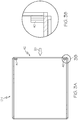
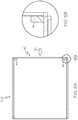
- FIG. 5A and 5B which are not an embodiment of the present invention, a result similar to that shown in Figures 4A and 4B may be achieved by inserting and brazing separate header bar segments 48 to block the flow 26 through a heat exchanger core 10-3.
- the flow 26 may naturally expand into the full passage width.
- extended metal pieces 50 with a normal profile similar to the header bar segments 48 of Figures 5A and 5B , can be extended in the dimension extending into the passage depth, thereby affirmatively blocking flow over a fixed area of the separator plates 18 (see Figure 1 ).
- the functional fin matrix may be notched to accommodate the profile of these edge blocking segments (extended metal pieces 50).
Landscapes
- Engineering & Computer Science (AREA)
- Mechanical Engineering (AREA)
- Physics & Mathematics (AREA)
- Thermal Sciences (AREA)
- General Engineering & Computer Science (AREA)
- Heat-Exchange Devices With Radiators And Conduit Assemblies (AREA)
Claims (5)
- Stapelscheibenwärmetauscher (10), der Folgendes umfasst:zwei Wärmetauscherseitenplatten (12);mehrere Metalltrennplatten (18);wobei die Seitenplatten (12) einen gesamten Stapel der alternierenden Durchgänge (14, 16) stützen, wobei jeweils zwei der Durchgänge (14, 16) durch eine der Metalltrennplatten (18) abgetrennt werden,gekennzeichnet durch:einen Eckentemperaturdämpfer, der Folgendes umfasst:mehrere Eckenwinkelstücke (22), wobei jedes ein dünnes Winkelstück ist und eine Dreiecksform aufweist, die dazu ausgeführt ist, eine vorbestimmte Menge an Einlassstrom (26), die einer Höhe der Eckenwinkelstücke (22) entspricht, zu jedem anderen Durchgang in einem Stapel von Durchgängen (14, 16) in dem Wärmetauscher zu blockieren, beginnend bei einem von jedem Ende des Stapels nach innen gelegenen zweiten Durchgang.
- Stapelscheibenwärmetauscher nach Anspruch 1, der ferner eine Einlasskernseite (24) umfasst, wobei die Eckenwinkelstücke (22) senkrecht zum Einlassstrom an Ecken der Kernseite (24) des Wärmetauschers angeordnet sind.
- Stapelscheibenwärmetauscher nach Anspruch 2, wobei die Eckenwinkelstücke (22) die Form eines rechtwinkligen Dreiecks aufweisen.
- Stapelscheibenwärmetauscher nach Anspruch 3, der ferner einen Einlassverteiler (34) umfasst, der an der Einlasskernseite (24) befestigt ist, wobei die Eckenwinkelstücke (32) an Ecken des Einlassverteilers (34) des Wärmetauschers angeordnet sind.
- Stapelscheibenwärmetauscher nach Anspruch 4, wobei jedes der Eckenblockierungswinkelstücke (32) eine Basis (28) aufweist, die an der nächsten Seitenplatte (12) derart angebracht ist, dass sich jedes der Eckenblockierungswinkelstücke, die eine dreieckige Querschnittsform aufweisen, zu einer Mittellinie (30) der Durchgänge (14) hin verjüngt.
Applications Claiming Priority (1)
| Application Number | Priority Date | Filing Date | Title |
|---|---|---|---|
| US13/208,309 US9151548B2 (en) | 2011-08-11 | 2011-08-11 | High temperature heat exchanger corner metal temperature attenuator |
Publications (2)
| Publication Number | Publication Date |
|---|---|
| EP2557384A1 EP2557384A1 (de) | 2013-02-13 |
| EP2557384B1 true EP2557384B1 (de) | 2018-02-21 |
Family
ID=46603692
Family Applications (1)
| Application Number | Title | Priority Date | Filing Date |
|---|---|---|---|
| EP12178569.5A Not-in-force EP2557384B1 (de) | 2011-08-11 | 2012-07-30 | Eckenmetall-Temperaturdämpfer für Hochtemperatur-Wärmetauscher |
Country Status (2)
| Country | Link |
|---|---|
| US (1) | US9151548B2 (de) |
| EP (1) | EP2557384B1 (de) |
Families Citing this family (3)
| Publication number | Priority date | Publication date | Assignee | Title |
|---|---|---|---|---|
| US9671178B2 (en) * | 2013-08-09 | 2017-06-06 | Hamilton Sundstrand Corporation | Heat exchanger thermal fatigue stress reduction |
| US20160377350A1 (en) * | 2015-06-29 | 2016-12-29 | Honeywell International Inc. | Optimized plate fin heat exchanger for improved compliance to improve thermal life |
| CN110486975B (zh) * | 2019-08-29 | 2021-08-24 | 上海理工大学 | 二级矩形叠层微通道制冷器 |
Citations (1)
| Publication number | Priority date | Publication date | Assignee | Title |
|---|---|---|---|---|
| US4596285A (en) * | 1985-03-28 | 1986-06-24 | North Atlantic Technologies, Inc. | Heat exchanger with resilient corner seals |
Family Cites Families (15)
| Publication number | Priority date | Publication date | Assignee | Title |
|---|---|---|---|---|
| US2595308A (en) | 1948-03-03 | 1952-05-06 | Modine Mfg Co | Gas-to-gas heat exchanger |
| GB686431A (en) | 1950-01-31 | 1953-01-21 | Bataafsche Petroleum | Recuperative plate heat-exchanger |
| US3165151A (en) | 1962-04-09 | 1965-01-12 | Young Radiator Co | Heat-transfer trussed-radiator |
| US3196942A (en) | 1963-07-05 | 1965-07-27 | United Aircraft Corp | Heat exchanger construction including tubular closure plates |
| US3948317A (en) | 1973-02-16 | 1976-04-06 | Owens-Illinois, Inc. | Structural reinforced glass-ceramic matrix products and method |
| US4227570A (en) | 1979-10-01 | 1980-10-14 | Caterpillar Tractor Co. | Heat exchange structure |
| JPS59134776U (ja) * | 1983-02-28 | 1984-09-08 | 株式会社バ−ナ−インタ−ナシヨナル | 直交流型熱交換器 |
| US4551229A (en) | 1984-03-19 | 1985-11-05 | Chevron Research Company | Cracking of heavy hydrocarbons with improved yields of valuable liquid products |
| US4844151A (en) | 1986-12-23 | 1989-07-04 | Sundstrand Corporation | Heat exchanger apparatus |
| US5540899A (en) | 1994-12-22 | 1996-07-30 | Uop | BI-directional control of temperatures in reactant channels |
| US6675746B2 (en) | 1999-12-01 | 2004-01-13 | Advanced Mechanical Technology, Inc. | Heat exchanger with internal pin elements |
| US6997250B2 (en) | 2003-08-01 | 2006-02-14 | Honeywell International, Inc. | Heat exchanger with flow director |
| EP2169339B1 (de) | 2007-06-18 | 2015-07-22 | Mitsubishi Electric Corporation | Wärmeaustauschelement, verfahren zur herstellung des wärmeaustauschelements, wärmetauscher und wärmeaustausch- und lüftungsvorrichtung |
| FR2939879B1 (fr) * | 2008-12-15 | 2011-03-04 | Vitherm | Echangeur thermique a plaques soudees |
| NL2004565C2 (en) * | 2010-04-16 | 2011-10-18 | Mircea Dinulescu | Plate type heat exchanger having outer heat exchanger plates with improved connections to end panels. |
-
2011
- 2011-08-11 US US13/208,309 patent/US9151548B2/en active Active
-
2012
- 2012-07-30 EP EP12178569.5A patent/EP2557384B1/de not_active Not-in-force
Patent Citations (1)
| Publication number | Priority date | Publication date | Assignee | Title |
|---|---|---|---|---|
| US4596285A (en) * | 1985-03-28 | 1986-06-24 | North Atlantic Technologies, Inc. | Heat exchanger with resilient corner seals |
Also Published As
| Publication number | Publication date |
|---|---|
| EP2557384A1 (de) | 2013-02-13 |
| US9151548B2 (en) | 2015-10-06 |
| US20130037247A1 (en) | 2013-02-14 |
Similar Documents
| Publication | Publication Date | Title |
|---|---|---|
| US10222142B2 (en) | Heat exchanger designs using variable geometries and configurations | |
| EP2410278B1 (de) | Plattenwärmetauscher und kälte-klimatisierungsvorrichtung | |
| EP3553447A1 (de) | Wärmeverstärkungsmerkmale in einem gegossenen wärmetauscher | |
| JP5772748B2 (ja) | 蒸発器 | |
| US20170211896A1 (en) | Heat exchanger with center manifold | |
| US20140290920A1 (en) | Air to air heat exchanger | |
| US20160377350A1 (en) | Optimized plate fin heat exchanger for improved compliance to improve thermal life | |
| US9151548B2 (en) | High temperature heat exchanger corner metal temperature attenuator | |
| US12013194B2 (en) | Asymmetric cross counter flow heat exchanger | |
| EP3537084B1 (de) | Segmentierte rippen für einen gegossenen wärmetauscher | |
| JP4079119B2 (ja) | 熱交換器 | |
| EP3176533A1 (de) | Querstromkeramikwärmetauscher und verfahren zur herstellung | |
| EP4067800A1 (de) | Wärmetauscher | |
| EP3734213B1 (de) | Versetzter/schräger kreuzgegenstrom-wärmetauscher | |
| US20160025007A1 (en) | Plate heat exchanger of improved thermal efficiency for a turboshaft engine | |
| EP3553448B1 (de) | Sekundär angewendetes kaltseitenfeatures für gegossenen wärmetauscher | |
| US20210033352A1 (en) | Plate fin crossflow heat exchanger | |
| EP3043138B1 (de) | Wärmetauscher mit wellenförmiger rippenstruktur. | |
| EP4385736A1 (de) | Variable durchgänge für optimierung von delta p und wärmeübertragung entlang des strömungswegs | |
| EP3754280A1 (de) | Wärmetauscherverschlussriegel | |
| US10330391B2 (en) | Heat exchanger assembly | |
| EP4008985B1 (de) | Wärmetauscher für temperaturen unter dem gefrierpunkt mit separatem schmelzfluid | |
| US20170363369A1 (en) | Reduced thermal expansion closure bars for a heat exchanger | |
| US20080202731A1 (en) | One-Piece Turbulence Insert | |
| CN108088278B (zh) | 一种改善液体分布不均的板翅式换热器翅片组件及换热器 |
Legal Events
| Date | Code | Title | Description |
|---|---|---|---|
| PUAI | Public reference made under article 153(3) epc to a published international application that has entered the european phase |
Free format text: ORIGINAL CODE: 0009012 |
|
| 17P | Request for examination filed |
Effective date: 20120730 |
|
| AK | Designated contracting states |
Kind code of ref document: A1 Designated state(s): AL AT BE BG CH CY CZ DE DK EE ES FI FR GB GR HR HU IE IS IT LI LT LU LV MC MK MT NL NO PL PT RO RS SE SI SK SM TR |
|
| AX | Request for extension of the european patent |
Extension state: BA ME |
|
| 17Q | First examination report despatched |
Effective date: 20130123 |
|
| RAP1 | Party data changed (applicant data changed or rights of an application transferred) |
Owner name: HONEYWELL INTERNATIONAL INC. |
|
| GRAP | Despatch of communication of intention to grant a patent |
Free format text: ORIGINAL CODE: EPIDOSNIGR1 |
|
| RIC1 | Information provided on ipc code assigned before grant |
Ipc: F28F 13/14 20060101ALI20170911BHEP Ipc: F28F 13/06 20060101ALI20170911BHEP Ipc: F28F 9/20 20060101ALI20170911BHEP Ipc: F28D 9/00 20060101AFI20170911BHEP Ipc: F28F 9/02 20060101ALI20170911BHEP Ipc: B23K 1/00 20060101ALN20170911BHEP |
|
| INTG | Intention to grant announced |
Effective date: 20171004 |
|
| GRAS | Grant fee paid |
Free format text: ORIGINAL CODE: EPIDOSNIGR3 |
|
| GRAA | (expected) grant |
Free format text: ORIGINAL CODE: 0009210 |
|
| AK | Designated contracting states |
Kind code of ref document: B1 Designated state(s): AL AT BE BG CH CY CZ DE DK EE ES FI FR GB GR HR HU IE IS IT LI LT LU LV MC MK MT NL NO PL PT RO RS SE SI SK SM TR |
|
| REG | Reference to a national code |
Ref country code: GB Ref legal event code: FG4D |
|
| REG | Reference to a national code |
Ref country code: CH Ref legal event code: EP |
|
| REG | Reference to a national code |
Ref country code: AT Ref legal event code: REF Ref document number: 972220 Country of ref document: AT Kind code of ref document: T Effective date: 20180315 |
|
| REG | Reference to a national code |
Ref country code: IE Ref legal event code: FG4D |
|
| REG | Reference to a national code |
Ref country code: DE Ref legal event code: R096 Ref document number: 602012042962 Country of ref document: DE |
|
| REG | Reference to a national code |
Ref country code: NL Ref legal event code: MP Effective date: 20180221 |
|
| REG | Reference to a national code |
Ref country code: LT Ref legal event code: MG4D |
|
| REG | Reference to a national code |
Ref country code: AT Ref legal event code: MK05 Ref document number: 972220 Country of ref document: AT Kind code of ref document: T Effective date: 20180221 |
|
| PG25 | Lapsed in a contracting state [announced via postgrant information from national office to epo] |
Ref country code: LT Free format text: LAPSE BECAUSE OF FAILURE TO SUBMIT A TRANSLATION OF THE DESCRIPTION OR TO PAY THE FEE WITHIN THE PRESCRIBED TIME-LIMIT Effective date: 20180221 Ref country code: NL Free format text: LAPSE BECAUSE OF FAILURE TO SUBMIT A TRANSLATION OF THE DESCRIPTION OR TO PAY THE FEE WITHIN THE PRESCRIBED TIME-LIMIT Effective date: 20180221 Ref country code: NO Free format text: LAPSE BECAUSE OF FAILURE TO SUBMIT A TRANSLATION OF THE DESCRIPTION OR TO PAY THE FEE WITHIN THE PRESCRIBED TIME-LIMIT Effective date: 20180521 Ref country code: ES Free format text: LAPSE BECAUSE OF FAILURE TO SUBMIT A TRANSLATION OF THE DESCRIPTION OR TO PAY THE FEE WITHIN THE PRESCRIBED TIME-LIMIT Effective date: 20180221 Ref country code: HR Free format text: LAPSE BECAUSE OF FAILURE TO SUBMIT A TRANSLATION OF THE DESCRIPTION OR TO PAY THE FEE WITHIN THE PRESCRIBED TIME-LIMIT Effective date: 20180221 Ref country code: FI Free format text: LAPSE BECAUSE OF FAILURE TO SUBMIT A TRANSLATION OF THE DESCRIPTION OR TO PAY THE FEE WITHIN THE PRESCRIBED TIME-LIMIT Effective date: 20180221 Ref country code: CY Free format text: LAPSE BECAUSE OF FAILURE TO SUBMIT A TRANSLATION OF THE DESCRIPTION OR TO PAY THE FEE WITHIN THE PRESCRIBED TIME-LIMIT Effective date: 20180221 |
|
| PG25 | Lapsed in a contracting state [announced via postgrant information from national office to epo] |
Ref country code: LV Free format text: LAPSE BECAUSE OF FAILURE TO SUBMIT A TRANSLATION OF THE DESCRIPTION OR TO PAY THE FEE WITHIN THE PRESCRIBED TIME-LIMIT Effective date: 20180221 Ref country code: SE Free format text: LAPSE BECAUSE OF FAILURE TO SUBMIT A TRANSLATION OF THE DESCRIPTION OR TO PAY THE FEE WITHIN THE PRESCRIBED TIME-LIMIT Effective date: 20180221 Ref country code: RS Free format text: LAPSE BECAUSE OF FAILURE TO SUBMIT A TRANSLATION OF THE DESCRIPTION OR TO PAY THE FEE WITHIN THE PRESCRIBED TIME-LIMIT Effective date: 20180221 Ref country code: GR Free format text: LAPSE BECAUSE OF FAILURE TO SUBMIT A TRANSLATION OF THE DESCRIPTION OR TO PAY THE FEE WITHIN THE PRESCRIBED TIME-LIMIT Effective date: 20180522 Ref country code: BG Free format text: LAPSE BECAUSE OF FAILURE TO SUBMIT A TRANSLATION OF THE DESCRIPTION OR TO PAY THE FEE WITHIN THE PRESCRIBED TIME-LIMIT Effective date: 20180521 Ref country code: AT Free format text: LAPSE BECAUSE OF FAILURE TO SUBMIT A TRANSLATION OF THE DESCRIPTION OR TO PAY THE FEE WITHIN THE PRESCRIBED TIME-LIMIT Effective date: 20180221 |
|
| PG25 | Lapsed in a contracting state [announced via postgrant information from national office to epo] |
Ref country code: AL Free format text: LAPSE BECAUSE OF FAILURE TO SUBMIT A TRANSLATION OF THE DESCRIPTION OR TO PAY THE FEE WITHIN THE PRESCRIBED TIME-LIMIT Effective date: 20180221 Ref country code: IT Free format text: LAPSE BECAUSE OF FAILURE TO SUBMIT A TRANSLATION OF THE DESCRIPTION OR TO PAY THE FEE WITHIN THE PRESCRIBED TIME-LIMIT Effective date: 20180221 Ref country code: PL Free format text: LAPSE BECAUSE OF FAILURE TO SUBMIT A TRANSLATION OF THE DESCRIPTION OR TO PAY THE FEE WITHIN THE PRESCRIBED TIME-LIMIT Effective date: 20180221 Ref country code: EE Free format text: LAPSE BECAUSE OF FAILURE TO SUBMIT A TRANSLATION OF THE DESCRIPTION OR TO PAY THE FEE WITHIN THE PRESCRIBED TIME-LIMIT Effective date: 20180221 Ref country code: RO Free format text: LAPSE BECAUSE OF FAILURE TO SUBMIT A TRANSLATION OF THE DESCRIPTION OR TO PAY THE FEE WITHIN THE PRESCRIBED TIME-LIMIT Effective date: 20180221 |
|
| REG | Reference to a national code |
Ref country code: DE Ref legal event code: R097 Ref document number: 602012042962 Country of ref document: DE |
|
| PG25 | Lapsed in a contracting state [announced via postgrant information from national office to epo] |
Ref country code: SM Free format text: LAPSE BECAUSE OF FAILURE TO SUBMIT A TRANSLATION OF THE DESCRIPTION OR TO PAY THE FEE WITHIN THE PRESCRIBED TIME-LIMIT Effective date: 20180221 Ref country code: SK Free format text: LAPSE BECAUSE OF FAILURE TO SUBMIT A TRANSLATION OF THE DESCRIPTION OR TO PAY THE FEE WITHIN THE PRESCRIBED TIME-LIMIT Effective date: 20180221 Ref country code: CZ Free format text: LAPSE BECAUSE OF FAILURE TO SUBMIT A TRANSLATION OF THE DESCRIPTION OR TO PAY THE FEE WITHIN THE PRESCRIBED TIME-LIMIT Effective date: 20180221 Ref country code: DK Free format text: LAPSE BECAUSE OF FAILURE TO SUBMIT A TRANSLATION OF THE DESCRIPTION OR TO PAY THE FEE WITHIN THE PRESCRIBED TIME-LIMIT Effective date: 20180221 |
|
| PLBE | No opposition filed within time limit |
Free format text: ORIGINAL CODE: 0009261 |
|
| STAA | Information on the status of an ep patent application or granted ep patent |
Free format text: STATUS: NO OPPOSITION FILED WITHIN TIME LIMIT |
|
| 26N | No opposition filed |
Effective date: 20181122 |
|
| PG25 | Lapsed in a contracting state [announced via postgrant information from national office to epo] |
Ref country code: SI Free format text: LAPSE BECAUSE OF FAILURE TO SUBMIT A TRANSLATION OF THE DESCRIPTION OR TO PAY THE FEE WITHIN THE PRESCRIBED TIME-LIMIT Effective date: 20180221 |
|
| REG | Reference to a national code |
Ref country code: CH Ref legal event code: PL |
|
| PG25 | Lapsed in a contracting state [announced via postgrant information from national office to epo] |
Ref country code: MC Free format text: LAPSE BECAUSE OF FAILURE TO SUBMIT A TRANSLATION OF THE DESCRIPTION OR TO PAY THE FEE WITHIN THE PRESCRIBED TIME-LIMIT Effective date: 20180221 Ref country code: LU Free format text: LAPSE BECAUSE OF NON-PAYMENT OF DUE FEES Effective date: 20180730 |
|
| REG | Reference to a national code |
Ref country code: BE Ref legal event code: MM Effective date: 20180731 |
|
| PG25 | Lapsed in a contracting state [announced via postgrant information from national office to epo] |
Ref country code: CH Free format text: LAPSE BECAUSE OF NON-PAYMENT OF DUE FEES Effective date: 20180731 Ref country code: LI Free format text: LAPSE BECAUSE OF NON-PAYMENT OF DUE FEES Effective date: 20180731 Ref country code: FR Free format text: LAPSE BECAUSE OF NON-PAYMENT OF DUE FEES Effective date: 20180731 |
|
| REG | Reference to a national code |
Ref country code: IE Ref legal event code: MM4A |
|
| PG25 | Lapsed in a contracting state [announced via postgrant information from national office to epo] |
Ref country code: BE Free format text: LAPSE BECAUSE OF NON-PAYMENT OF DUE FEES Effective date: 20180731 |
|
| PG25 | Lapsed in a contracting state [announced via postgrant information from national office to epo] |
Ref country code: IE Free format text: LAPSE BECAUSE OF NON-PAYMENT OF DUE FEES Effective date: 20180730 |
|
| PG25 | Lapsed in a contracting state [announced via postgrant information from national office to epo] |
Ref country code: MT Free format text: LAPSE BECAUSE OF NON-PAYMENT OF DUE FEES Effective date: 20180730 |
|
| PG25 | Lapsed in a contracting state [announced via postgrant information from national office to epo] |
Ref country code: TR Free format text: LAPSE BECAUSE OF FAILURE TO SUBMIT A TRANSLATION OF THE DESCRIPTION OR TO PAY THE FEE WITHIN THE PRESCRIBED TIME-LIMIT Effective date: 20180221 |
|
| PG25 | Lapsed in a contracting state [announced via postgrant information from national office to epo] |
Ref country code: PT Free format text: LAPSE BECAUSE OF FAILURE TO SUBMIT A TRANSLATION OF THE DESCRIPTION OR TO PAY THE FEE WITHIN THE PRESCRIBED TIME-LIMIT Effective date: 20180221 Ref country code: HU Free format text: LAPSE BECAUSE OF FAILURE TO SUBMIT A TRANSLATION OF THE DESCRIPTION OR TO PAY THE FEE WITHIN THE PRESCRIBED TIME-LIMIT; INVALID AB INITIO Effective date: 20120730 |
|
| PG25 | Lapsed in a contracting state [announced via postgrant information from national office to epo] |
Ref country code: MK Free format text: LAPSE BECAUSE OF NON-PAYMENT OF DUE FEES Effective date: 20180221 |
|
| PG25 | Lapsed in a contracting state [announced via postgrant information from national office to epo] |
Ref country code: IS Free format text: LAPSE BECAUSE OF FAILURE TO SUBMIT A TRANSLATION OF THE DESCRIPTION OR TO PAY THE FEE WITHIN THE PRESCRIBED TIME-LIMIT Effective date: 20180621 |
|
| PGFP | Annual fee paid to national office [announced via postgrant information from national office to epo] |
Ref country code: GB Payment date: 20220719 Year of fee payment: 11 Ref country code: DE Payment date: 20220727 Year of fee payment: 11 |
|
| P01 | Opt-out of the competence of the unified patent court (upc) registered |
Effective date: 20230525 |
|
| REG | Reference to a national code |
Ref country code: DE Ref legal event code: R119 Ref document number: 602012042962 Country of ref document: DE |
|
| GBPC | Gb: european patent ceased through non-payment of renewal fee |
Effective date: 20230730 |
|
| PG25 | Lapsed in a contracting state [announced via postgrant information from national office to epo] |
Ref country code: DE Free format text: LAPSE BECAUSE OF NON-PAYMENT OF DUE FEES Effective date: 20240201 Ref country code: GB Free format text: LAPSE BECAUSE OF NON-PAYMENT OF DUE FEES Effective date: 20230730 |