EP2555811B1 - Endoprosthesis - Google Patents
Endoprosthesis Download PDFInfo
- Publication number
- EP2555811B1 EP2555811B1 EP11710645.0A EP11710645A EP2555811B1 EP 2555811 B1 EP2555811 B1 EP 2555811B1 EP 11710645 A EP11710645 A EP 11710645A EP 2555811 B1 EP2555811 B1 EP 2555811B1
- Authority
- EP
- European Patent Office
- Prior art keywords
- stent
- metal
- core
- bio
- strut
- Prior art date
- Legal status (The legal status is an assumption and is not a legal conclusion. Google has not performed a legal analysis and makes no representation as to the accuracy of the status listed.)
- Not-in-force
Links
Images


Classifications
-
- A—HUMAN NECESSITIES
- A61—MEDICAL OR VETERINARY SCIENCE; HYGIENE
- A61L—METHODS OR APPARATUS FOR STERILISING MATERIALS OR OBJECTS IN GENERAL; DISINFECTION, STERILISATION OR DEODORISATION OF AIR; CHEMICAL ASPECTS OF BANDAGES, DRESSINGS, ABSORBENT PADS OR SURGICAL ARTICLES; MATERIALS FOR BANDAGES, DRESSINGS, ABSORBENT PADS OR SURGICAL ARTICLES
- A61L31/00—Materials for other surgical articles, e.g. stents, stent-grafts, shunts, surgical drapes, guide wires, materials for adhesion prevention, occluding devices, surgical gloves, tissue fixation devices
- A61L31/08—Materials for coatings
- A61L31/082—Inorganic materials
- A61L31/088—Other specific inorganic materials not covered by A61L31/084 or A61L31/086
-
- A—HUMAN NECESSITIES
- A61—MEDICAL OR VETERINARY SCIENCE; HYGIENE
- A61L—METHODS OR APPARATUS FOR STERILISING MATERIALS OR OBJECTS IN GENERAL; DISINFECTION, STERILISATION OR DEODORISATION OF AIR; CHEMICAL ASPECTS OF BANDAGES, DRESSINGS, ABSORBENT PADS OR SURGICAL ARTICLES; MATERIALS FOR BANDAGES, DRESSINGS, ABSORBENT PADS OR SURGICAL ARTICLES
- A61L31/00—Materials for other surgical articles, e.g. stents, stent-grafts, shunts, surgical drapes, guide wires, materials for adhesion prevention, occluding devices, surgical gloves, tissue fixation devices
- A61L31/04—Macromolecular materials
- A61L31/043—Proteins; Polypeptides; Degradation products thereof
- A61L31/044—Collagen
-
- A—HUMAN NECESSITIES
- A61—MEDICAL OR VETERINARY SCIENCE; HYGIENE
- A61L—METHODS OR APPARATUS FOR STERILISING MATERIALS OR OBJECTS IN GENERAL; DISINFECTION, STERILISATION OR DEODORISATION OF AIR; CHEMICAL ASPECTS OF BANDAGES, DRESSINGS, ABSORBENT PADS OR SURGICAL ARTICLES; MATERIALS FOR BANDAGES, DRESSINGS, ABSORBENT PADS OR SURGICAL ARTICLES
- A61L31/00—Materials for other surgical articles, e.g. stents, stent-grafts, shunts, surgical drapes, guide wires, materials for adhesion prevention, occluding devices, surgical gloves, tissue fixation devices
- A61L31/04—Macromolecular materials
- A61L31/06—Macromolecular materials obtained otherwise than by reactions only involving carbon-to-carbon unsaturated bonds
-
- A—HUMAN NECESSITIES
- A61—MEDICAL OR VETERINARY SCIENCE; HYGIENE
- A61L—METHODS OR APPARATUS FOR STERILISING MATERIALS OR OBJECTS IN GENERAL; DISINFECTION, STERILISATION OR DEODORISATION OF AIR; CHEMICAL ASPECTS OF BANDAGES, DRESSINGS, ABSORBENT PADS OR SURGICAL ARTICLES; MATERIALS FOR BANDAGES, DRESSINGS, ABSORBENT PADS OR SURGICAL ARTICLES
- A61L31/00—Materials for other surgical articles, e.g. stents, stent-grafts, shunts, surgical drapes, guide wires, materials for adhesion prevention, occluding devices, surgical gloves, tissue fixation devices
- A61L31/08—Materials for coatings
- A61L31/10—Macromolecular materials
-
- A—HUMAN NECESSITIES
- A61—MEDICAL OR VETERINARY SCIENCE; HYGIENE
- A61L—METHODS OR APPARATUS FOR STERILISING MATERIALS OR OBJECTS IN GENERAL; DISINFECTION, STERILISATION OR DEODORISATION OF AIR; CHEMICAL ASPECTS OF BANDAGES, DRESSINGS, ABSORBENT PADS OR SURGICAL ARTICLES; MATERIALS FOR BANDAGES, DRESSINGS, ABSORBENT PADS OR SURGICAL ARTICLES
- A61L31/00—Materials for other surgical articles, e.g. stents, stent-grafts, shunts, surgical drapes, guide wires, materials for adhesion prevention, occluding devices, surgical gloves, tissue fixation devices
- A61L31/14—Materials characterised by their function or physical properties, e.g. injectable or lubricating compositions, shape-memory materials, surface modified materials
- A61L31/148—Materials at least partially resorbable by the body
-
- A—HUMAN NECESSITIES
- A61—MEDICAL OR VETERINARY SCIENCE; HYGIENE
- A61L—METHODS OR APPARATUS FOR STERILISING MATERIALS OR OBJECTS IN GENERAL; DISINFECTION, STERILISATION OR DEODORISATION OF AIR; CHEMICAL ASPECTS OF BANDAGES, DRESSINGS, ABSORBENT PADS OR SURGICAL ARTICLES; MATERIALS FOR BANDAGES, DRESSINGS, ABSORBENT PADS OR SURGICAL ARTICLES
- A61L31/00—Materials for other surgical articles, e.g. stents, stent-grafts, shunts, surgical drapes, guide wires, materials for adhesion prevention, occluding devices, surgical gloves, tissue fixation devices
- A61L31/14—Materials characterised by their function or physical properties, e.g. injectable or lubricating compositions, shape-memory materials, surface modified materials
- A61L31/16—Biologically active materials, e.g. therapeutic substances
-
- Y—GENERAL TAGGING OF NEW TECHNOLOGICAL DEVELOPMENTS; GENERAL TAGGING OF CROSS-SECTIONAL TECHNOLOGIES SPANNING OVER SEVERAL SECTIONS OF THE IPC; TECHNICAL SUBJECTS COVERED BY FORMER USPC CROSS-REFERENCE ART COLLECTIONS [XRACs] AND DIGESTS
- Y10—TECHNICAL SUBJECTS COVERED BY FORMER USPC
- Y10T—TECHNICAL SUBJECTS COVERED BY FORMER US CLASSIFICATION
- Y10T29/00—Metal working
- Y10T29/49—Method of mechanical manufacture
- Y10T29/49826—Assembling or joining
Definitions
- This invention relates to stents.
- the body includes various passageways such as arteries, other blood vessels and other body lumens. These passageways sometimes become occluded or weakened. For example, the passageways can be occluded by a tumor, restricted by plaque, or weakened by an aneurysm. When this occurs, the passageway can be reopened or reinforced with a medical stent.
- An stent is typically a tubular member that is placed in a lumen in the body. Examples of endoprostheses include stents, covered stents, and stent-grafts.
- Endoprostheses such as stents can be delivered inside the body by a catheter that supports the stent in a compacted or reduced-size form as the stent is transported to a desired site. Upon reaching the site, the stent is expanded, e.g., so that it can contact the walls of the lumen. Stent delivery is further discussed in Heath, U.S. 6,290,721 .
- the expansion mechanism may include forcing the stent to expand radially.
- the expansion mechanism can include the catheter carrying a balloon, which carries a balloon-expandable stent.
- the balloon can be inflated to deform and to fix the expanded stent at a predetermined position in contact with the lumen wall.
- the balloon can then be deflated, and the catheter withdrawn from the lumen.
- the invention features a bio-erodible implantable stent as further defined in appended claim 1.
- the core comprises a bio-erodible polymer.
- the bio-erodible polymer is PLA, PLGA, or a combination thereof.
- the core comprises a collagen.
- the core includes a drug.
- the core includes radiopaque particles.
- the bio-erodible metal comprises iron or an alloy thereof.
- the bio-erodible metal comprises magnesium or an alloy thereof.
- the bio-erodible metal comprises a plurality of pores through which physiological fluids can access the core upon implantation.
- the pores are micron-sized pores having a diameter of about 1 micron to about 20 microns.
- the bio-erodible metal is provided with channels through which physiological fluids can access the core upon implantation.
- the bio-erodible metal is in the form of a mesh.
- the bio-erodible metal has a thickness of about 20 microns to about 40 microns.
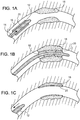
- a stent 20 is placed over a balloon 12 carried near a distal end of a catheter 14, and is directed through the lumen 16 ( figure 1A ) until the portion carrying the balloon and stent reaches the region of an occlusion 18.
- the stent 20 is then radially expanded by inflating the balloon 12 and compressed against the vessel wall with the result that occlusion 18 is compressed, and the vessel wall surrounding it undergoes a radial expansion ( figure 1B ).
- the pressure is then released from the balloon and the catheter is withdrawn from the vessel ( figure 1C ).
- an expandable stent 20 can have a stent body having the form of a tubular member defined by a plurality of bands 22 and a plurality of connectors 24 that extend between and connect adjacent bands.
- bands 22 can be expanded from an initial, smaller diameter to a larger diameter to contact stent 20 against a wall of a vessel, thereby maintaining the patency of the vessel.
- Connectors 24 can provide stent 20 with flexibility and conformability that allow the stent to adapt to the contours of the vessel.
- One or more bands 22 form acute angles 23. The angle 23 increases upon expansion of the stent.
- Stent body 20, bands 22 and connectors 24 can have a luminal surface 26, an abluminal surface 28, and a sidewall surface 29.
- the bands and/or connectors have a width, W, and a thickness, T, of about 50 to 150 microns.
- the stent 20 can be a biodegradable stent that degrades after being delivered into a body lumen and being in contact with a body lumen.
- the bands 22 and the connectors 24 can include a biodegradable material, for example, a biodegradable polymer, such as polylactic acid (PLA), poly(lactic-co-glycolic acid) (PLGA), or polyelectrolyte complexes such as heparin ⁇ chitosan, carboxymethyl cellulose, and aminoalkyl methacrylate copolymer, a biodegradable metal, such as iron, iron alloy, tungsten, tungsten alloy, magnesium, magnesium alloy, a biodegradable metal oxide, such as magnesium oxide, calcium oxide, or other materials, such as collagen.
- a biodegradable polymer such as polylactic acid (PLA), poly(lactic-co-glycolic acid) (PLGA), or polyelectrolyte complexes such as heparin ⁇ chitosan, carboxy
- the stent wall includes a combination of materials, such as a metal and a polymer, arranged to provide advantageous mechanical properties, biodegradability, and drug delivery.
- the volume of the stent material included in the stent 20 is selected, for example, minimized, so that a limited, e.g., minimal, amount of degraded stent material is disposed in the body lumen and imposes a controlled, e.g., minimal, biological effect on the body at a cellular level.
- the volume of the stent 20 and the stent material are selected to provide a desired mechanical strength, e.g., radial strength, for expansion of the stent 20 and for supporting the stent 20 in the expanded state for a required length of time t , e.g., about a month to about three months.
- the biodegradable stent 20 can prevent galvanic reactions between the stent and a body fluid or body tissue when the stent is in use.
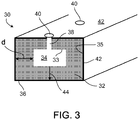
- a hollow stent strut 30 (components of the bands and the connectors) includes an inner layer 32 having an interior surface 33 surrounding a hollow interior 34 and an outer layer 36 on an exterior surface 35 of the inner layer 32.
- the hollow interior 34 is connected to the exterior of the strut 30 through pathways 38 in the inner and outer layers 32, 36 (not all shown), and ports 40 in the outer layer 36.
- the body fluid contacts both an external surface 42 of the outer layer 36 and the interior surface 33 of the inner layer 32 and the strut 30 corrodes from both the inside and the outside.
- the strut 30 corrodes in an inside-out manner, i.e., substantially from the hollow interior 34, e.g., for about one month, before the second layer 36 is corroded to expose the exterior surface 35 of the first layer 32 to the body fluid. During this time t , the mechanical strength of the strut 30 is substantially maintained. After the exposure of the exterior surface 35, the corrosion of the strut 30 accelerates.
- the inner layer 32 can include a metal that has an increasing density from the interior surface 33 to the exterior surface 35 along a radial direction 44.
- the low density portion of the inner layer 32 corrodes earlier and also faster than the high density portion, which further facilitates corroding the strut inside-out and maintaining the mechanical strength of the strut.
- the metal can be nanoporous metal foams having a thickness d of about 100 nm to about 50 microns.
- the diameters of the pores in the porous metal foams can be about 1 nm to about 5 nm.
- the metal foam can provide a mechanical strength similar to a bulk material having a similar thickness, while keeping the total volume of the stent material low.
- the nanoporous metal foams can be a three-dimensional network of high-strength or ultra-high-strength nanocolumns or nanowires, and can be highly porous.
- the nanoporous metal foams include about 5%, 10%, 15%, and/or up to about 20%, 25% pores by volume. A similar volume of the stent material is reduced in comparison with the bulk material.
- the porous structure of the foams provides a large surface area for the body fluid to contact the foams and the corrosion can be accelerated.
- Suitable metal for use in the inner layer 32 can include iron, magnesium, their alloys, or other biodegradable metals.
- Suitable material for use in the outer layer 36 can be a metal that corrodes more slowly than the metal in the inner layer 32.
- the outer layer 36 can include iron.
- the outer layer 36 can also be a biodegradable polymeric coating, for example, a PLGA coating or a PLA coating.
- additional particles such as metal particles or electroconductive polypyrole nanoparticles, can be disposed in the biodegradable polymeric coating to further reduce the corrosion rate and/or the mechanical strength of the outer layer 36.
- the thickness of the outer layer 36 can be chosen so that the outer layer 36 is substantially fully corroded before, at the same time as, or after the inner layer 32 is substantially fully corroded. Because the inner layer 32 is corroded inside-out and can be independent of the corrosion of the outer layer 36, the outer layer 36 can have a relatively thin thickness and low corrosion rate to reduce the total volume of the stent material.
- the strut 30 can carry a drug in the outer layer 36 that elutes when in contact with the body fluid.
- the drug can elute at a rate similar to the corrosion rate of the outer layer 36 and can last, for example, about a month.
- the length of time t before the outer layer 36 is corroded away and for the elution of the drug can be controlled by the thickness and/or corrosion rate of the layer 36.
- the inner layer 32 can also carry a drug, for example, in the pores of the porous foams. The drug in the inner layer 32 can have a higher elution rate than the elution rate of the drug in the outer layer 36.
- the strut 30 can contain radiopaque particles (not shown), such as gold nanoparticles, in the hollow interior 34.
- a gold nanoparticle layer can be formed on the interior surface 33 of the inner layer 32 to assist visualization of the stent at different functional stages, e.g., delivery or corrosion.
- the radiopaque particles can be co-deposited with metal particles that form the inner layer 32 using, for example, the Mantis technique (discussed below).
- the dimensions of the ports 40, the pathways 38, and the hollow interior 34 can also affect the time length t during which the stent is mechanically supported by the outer layer 36.
- small diameters of the ports 40 and pathways 38 can provide a long time length t .
- Each port 40 can have a diameter of about 0.5 micrometer to about 10 micrometers; the diameter of each pathway 38 can be about 0.5 micrometer to about 10 micrometers; and the hollow interior 34 can have in inner diameter of about 0.5 micrometer to about 50 micrometers.
- the ports 40 and the pathways 38 can be in the form of a continuous trench (not shown) indented from the surface 42 of the outer layer 36 and in the inner and outer layers 32, 36.
- the trench structure can allow the body fluid to reach the hollow interior 34 quickly and accelerates the corrosion.
- the ports 40 and/or the trench can be sealed by weak spots ( figure 4 ) in the outer layer 36.
- the inner layer 32 of the strut 30 does not start corroding until the weak spots are corroded away and the time length t can be extended.
- Other configurations and dimensions of the portions of the strut 30 can be used for obtaining a desired time length t , mechanical strength, drug elution profile, and/or corrosion rate of the strut.
- Figure 4 shows an example of making the stent strut 30.
- a thin polymer stent template 46 is provided (48), for example, by micro-molding. Information about the micro-molding technology is available, for example, from Sovrin Plastics at Slough, England.
- the dimensions of the template 46 can be selected based on the dimensions of the hollow interior (e.g., hollow interior 34 of figure 3 ) to be formed in the strut.
- Nanoporous metal networks 50, 54, 58 are sequentially formed (52a-52c) on the molded stent template 46 using, for example, a nano-cluster deposition system (IFC Medical or Mantis (UK)).
- nanosized metal particles e.g., iron particles
- carrying charges are accelerated towards the template 46 under a bias voltage.
- the particles collide with each other and with the template 46, and can partly melt, depending on their velocities.
- the nanoporous networks 50, 54, 58 are formed by the deposited particles.
- the Mantis technique is also discussed in U.S. provisional application No. 60/857,849 and U.S. application publication No. US 2008-0147177 .
- Different porosities of the nanoporous networks 50, 54, 58 can be obtained using particles having different sizes and by controlling the bias voltage at which these particles are deposited. Generally, larger particles and/or lower bias voltages create networks having higher porosities with larger pores. In the example shown in figure 4 , the bias voltages used in steps 52a, 52b, 52c increase from low to high and the networks 50, 54, 58 are created with decreased porosity and pore sizes. In some embodiments, the networks 50, 54, 58 having different porosities can be formed continuously using the same metal particles by changing the bias voltages continuously. The overall porosity of the networks 50, 54, 58 can increase continuously from the template 46 to the exterior network 58. In some embodiments, the networks 50, 54, 58 can be formed in separate steps. In different steps, the particle sizes can be changed in addition to the change of the bias voltages.
- the sizes of the metal particles used for the deposition can be between about 1 nm and about 1 micrometer.
- the bias voltage can be about 500 V to about 1000V, or even higher than 3000 V.
- the deposition rate is in the order of angstroms per second and it takes about 5 minutes to about 10 minutes of deposition time to form the networks 50, 54, 58 having a total thickness l of about 30 microns on when the template 46 has a thickness p of about 60 microns.
- a pathway 62 is formed (60), e.g., by laser ablation, in the networks 50, 54, 58 so that the template 46 is exposed to the exterior of the network 58.
- the template 46 is removed (64) from the interior of the network 50 by, for example, calcination, plasma etching, or chemical dissolution (along the direction 67).
- a hollow interior 66 that is surrounded by the network 50 is formed and is connected to the exterior of the networks through the pathway 62.
- a biodegradable polymeric coating 68 such as PLGA, is formed (70) on the network 58 by a coating process, for example, spraying, dipcoating, or plasma coating.
- a drug or additional particles such as electroconductive polypyrole nanoparticles, can be co-deposited with the polymer coating 68.
- one or more of a coating material for the polymeric coating 68, the drug, and the nanoparticles can be deposited simultaneously or in a sequential manner in various orders. The manner of the deposition of the drug and the nanoparticles relative to the coating material can affect the timing of the drug elution and the strength and corrosion of the stent.
- the drug when the drug is deposited after the deposition of the polymeric coating 68, the drug can elute from its initial contact with the body fluid once the stent is delivered; when the drug is deposited before the deposition of the polymer coating 68, the drug can elute through the pores of the networks 50, 54, 58 initially and also later from the pores formed in the corroded polymer layer 68.
- the opening of the pathway 62 to the exterior can be masked during the deposition of the polymer coating 68 so that the pathway 62 does not become sealed or blocked.
- a thin layer 72 continuous of the polymer coating can be formed over the pathway 62 and seals the pathway.
- the thin layer 72 can include a material the same as or different from the coating material in the polymer coating 68 and can have a thickness smaller than a thickness of the polymer coating 68.
- the thin layer 72 can have a thickness that is 1/10 to about 1/2 of the average thickness of the polymer coating 68. Penetration of the thin layer 72 can be established sooner than the penetration of the polymer coating 68, forming a port for the body fluid to enter the hollow interior 66 through the pathway 62.
- one or more drugs can be loaded into the networks 50, 54, 58, simultaneous to or after the formation of the networks and prior to the formation of the polymer coating 68.
- Methods suitable for the loading of the drugs include co-deposition of the metal nanoparticles and the drug component.
- the co-deposition can be performed by evaporating the drug in a heated boat at a temperature of about 80 Celsius degrees to about 120 Celsius degrees and forming condensation on the growing metal matrix.
- the drug/metal ratio can be changed by changing the metal deposition speed versus the evaporation speed of the drug.
- a thickness of the networks containing drugs can be controlled by deposition time.
- paclitaxel (Ptx) and tantalum (Ta) co-deposition are co-deposited for about 20 to about 40 minutes.
- the nanoparticles have a size of, e.g., about 50 nm. Adhesion of the coating formed by the metal nanoparticles and the drug component can be enhanced by cleaning the stent surface of foreign matter prior to depositing, e.g., using isopropyl alcohol (IPA) or plasma.
- IPA isopropyl alcohol
- the drugs in the networks 50, 54, 58 can be protected by the polymer coating 68 during delivery of the stent and are released after the thin layer 72 or the polymer coating 68 penetrates.
- a radiopaque material such as gold nanoparticles
- a radiopaque material can be incorporated in the template 46 in step 48, for example, by mixing the polymer material and the gold nanoparticles prior to the micromolding.
- the gold nanoparticles remain in the hollow interior 66 when the polymer template 46 is removed in step 64 and form a radiopaque layer on an interior surface 69 of the network 50.
- the radiopaque layer does not dissolve until the end of the stent corrosion and can facilitate tracking of the stent delivery and performance. For example, whether the stent has fully degraded can be observed using an X-ray.
- the gold nanoparticles have small sizes to enable removal of the particles by the body.
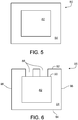
- a strut 80 has a polymer core 82 enclosed by metal shell 84.
- the metal shell 84 can have high mechanical strength and a high Young's modulus, and can determine the mechanical performance of the strut 80.
- the polymer core 82 has relatively low mechanical strength and a low Young's modulus.
- the metal shell 84 breaks unexpectedly, the polymer core 82 can also provide mechanical support for the strut. In use, the metal shell 84 degrades at a low rate for about 30 to about 90 days while substantially keeping the mechanical strength of the stent prior to substantially exposing the polymer core 82 to the body fluid.
- the mechanical strength of the stent decreases by about 10% to about 99% after 30 to 90 days.
- mechanical strength of a stent having an iron metal shell 84 decreases less than the mechanical strength of a stent having a magnesium metal shell 84, after the same amount of time.
- the length of time t before the metal shell 84 substantially degrades and the mechanical strength of the strut 80 can be controlled by the material used for and the thickness of the metal shell 84, and the thickness ratio of the shell 84 to the core 82.
- the metal shell 84 can have a thickness of about 1 micron to about 40 microns, about 10 microns to about 40 microns, or about 20 microns to about 40 microns.
- the dimensions of the cross-section of the strut 80 is about 50 microns by 50 microns. Once substantially exposed, the polymer core 82, and therefore, the strut 80, quickly degrades, for example, in about 20 days to about 90 days.
- the polymer core 82 can include polylactide (PLA) or PLGA, and optionally a drug, that are, for example, micro-injection-molded or laser-cut.
- the metal shell 84 includes fine, e.g., ultra-fine, grains of magnesium, iron, magnesium alloy, iron alloy, or other biodegradable metals, particles deposited using, for example, physical vapor deposition (PVD) or pulsed laser deposition (PLD).
- PVD physical vapor deposition
- PLD pulsed laser deposition
- the PLD process can reduce the thermal impact on the polymer core 82.
- the grains form of the metal shell 84 can enable the strut 80 to have a good ductility.
- the metal shell 84 substantially seals the polymer core 82 and the drug contained in the polymer core 82 does not release until one or more pores or channels are formed in the degrading metal shell 84 and the body fluid contacts the polymer core 82 through the pores or channels.
- the starting time of the drug release can be controlled by the parameters, such as the corrosion rate and the thickness, of the metal shell 84.
- the releasing rate and releasing profile of the drug can be adjusted by selecting the density of the drug in the polymer core 82 and the other related parameters, such as the sizes and the corrosion rate of, or the materials in the polymer core 82.
- the metal shell 84 of a strut 86 includes pores 88 that exposes a surface 90 of the polymer core 82 to the exterior of the metal shell 84.
- the drug in the polymer core 82 is exposed to the body fluid prior to substantial corrosion of the metal shell 84 and can be released at the early stage of the stent delivery.
- the pores 88 can have regular or irregular shapes and can have an average diameter of about 1 micron to about 20 microns.
- the pores 88 can be formed during or after the formation of the metal shell 84.
- colloidal lithography can be used by applying a mask to the polymer core 82 during the deposition of the metal shell to form the pores 88 at masked locations.
- the strut 86 can be formed by applying laser beams to the strut 80 to create pores 88 at intended locations (laser ablation). Other methods, such as etching can also be used.
- the pores 88 can be located on one or more surfaces of the strut 86, for example, abluminal surface 92, adluminal surface 94, and/or cut surfaces 96 of the strut.
- the pores 88 on the one or more of the surfaces can have a uniform density and/or average size.
- the pores 88 on one or more particular regions of a surface or a particular surface among all surfaces have a larger density or average size than the other regions or surfaces to release the drug at a high rate.
- Various configurations can used for different drug release profiles and corrosion time controls.
- the strut 80 of figure 5 or the strut 86 of figure 6 can be a portion of radial bands 100 and/or longitudinal connectors 102 of a stent 104 shown in figure 7 .
- the radial bands 100 is self-expandable or balloon-expandable and has a high Young's modulus to provide the strength to support the radial expansion of the stent.
- the longitudinal connectors 102 provides connections to the bands 100 and longitudinal flexibility to the stent 104.
- the stent 104 has metal shells (such as the metal shell 84 of figures 5 and 6 ) covering only the radial bands 100 to provide the bands with the desired mechanical strength.
- the uncovered polymer longitudinal connectors 102 can provide a high longitudinal flexibility and a high fatigue resistance.
- the stent 104 can be readily bent at locations along the longitudinal axis and can fit to the tortuous body lumen.
- the radial bands 100 made of a polymer material can be selectively coated with the metal shell by masking the longitudinal connectors 102 using a ring mask 103, which is positioned around segments of the stent connectors 102.
- Metal e.g., iron, particles are sputtered from targets 108 using PVD, e.g., magnetron sputtering with a hollow cathode, or PLD.
- PVD e.g., magnetron sputtering with a hollow cathode, or PLD.
- Other suitable masks and deposition methods can also be used to effectively coat the radial bands 100 without covering the connectors 102.
- a strut 110 includes a metal, e.g., iron, shell 114 encapsulating a collagen matrix 112 carrying metal oxide, e.g., iron oxide (FeOx), particles 116.
- metal oxide e.g., iron oxide (FeOx)
- the strut 110 undergoes a slow degradation of the metal shell, during which mechanical strength of the strut 110 is substantially maintained, followed by a rapid degradation of the collagen matrix 112 with the metal oxide particles 116.
- the metal oxide particles 116 can increase the mechanical strength of the collagen matrix so that the strut 110 can remain mechanically strong even after the degradation of the metal shell 114.
- a composite of a collagen material and the metal particles can be pre-made for making of the collagen matrix 112 containing the metal particles 116 by, for example, wet chemistry formulations.
- the metal particles can be incorporated into an anionic collagen prepared in an acidic environment. In some embodiments, a neutral collagen solution can be used.
- the metal particles can also be incorporated into the collagen by mechanical mixing. Methods of making the composition of the collagen with incorporated metal particles are discussed by Goissis et al., 10th international symposium on electrets (1999), pages 229-232 ; Goissis et al., Revista Brasileira de Engenharia Biomedica 15 (1999), pages 55-61 ; Berry et al., J. Phys. D: Appl.
- the collagen-metal oxide particle composition can be extruded or injection-molded into a desired shape for the strut 110. In some embodiments, laser cutting can also be used.
- the iron shell 114 having a desired thickness can be electroplated onto the collagen matrix 112. Other methods, such as PLD or PVD, electroless plating, metal fuse, can also be used.
- the iron shell 114 can have a thickness of about 100 nm to about several microns, e.g., about 200 nm to about 5000 nm. Suitable methods or control parameters in each method can be chosen for forming the iron shell having a particular thickness. For example, control of electroless plating parameters for iron deposition is described in Dinderman et al., Chem. Mater.
- Metal fuse to provide metal/polymer hybrids is developed, for example, by E.I. du Pont de Nemours and Company (DuPont). Metal fuse is also described in Day, Advanced Materials and Processes, 25-27 (April 2008). Other methods also include the methods for forming nano-coating developed by Integran Technologies Inc. (Pittsburg, PA).
- a strut 118 can include a metal mesh 120 surrounding the collagen matrix 124.
- the collagen matrix 124 can optionally include metal or metal oxide particles similar to the collagen matrix 112 of figure 8 .
- the collagen matrix 112 can be free of any metal or metal oxide particles.
- the collagen matrix 124 and the optional incorporation of the metal or metal oxide particles can be done in a way similar to the making of the collagen-metal oxide particle composition described previously.
- the mesh 120 can be deposited using a method similar to the deposition of the metal shell 114 of figure 8 , with an addition of one or more masks covering portions of the collagen matrix 124 where openings 122 are to be created.
- the openings 122 of the mesh shell 114 can also be created by laser ablation or other methods, similar to the creation of the openings 88 of figure 6 .
- the openings 122 can have an average diameter of about 1/20 to about 1/10 of a thickness of the strut 118.
- the thickness of the strut 118 can be selected based on, e.g., the material used for the strut, e.g., magnesium or iron, and the desired degradation profile.
- the opening 122 can have an average diameter of about 0.5 micrometer or about 10 micrometers.
- the strut 118 can have properties, such as mechanical strength or corrosion rate and duration, similar to the strut 110.
- metal-complex particles e.g., Fe complexations
- the produced metal-complex particles can be incorporated in the collagen matrix 124 to increase the mechanical strength of the collagen matrix, without having the collagen matrix 124 made with the metal or metal oxide particles 116 incorporated.
- an electrolyte solution body fluid
- the metallic Fe oxidizes to form Fe 2+ and Fe 3+ ions.
- the anionic collagen in the collagen matrix 124 can create an acidic environment by dissociation of carboxylic groups.
- the collagen can also be functionalized by an amine, a hydroxyl, or a thiol group.
- the Fe cations form complexes/salts with the dissociated COO - groups.
- the collagen in the collagen matrix can have a low molecular weight, for example, of about 40 KDaltons to about 60KDaltons and can be soluble or in the form of a gel.
- the formed iron complexation and the collagen matrix 124 can together be soluble. Iron complexation formation is also discussed by Shears et al., J. Food Sci. Techn. 22 (1987), pages 265-272 and Yu et al., Chinese Journal of Polymer Science 8 (1990), pages 247-252 .
- the solubility of the collagen is discussed by Wolf et al., IUFoST 20060929 (2006 ).
- other polymers that have functional groups capable of forming complexes with iron can also be used in replacement of or together with the collagen in the collagen matrix 124.
- the other polymers can include polyelectrolytes, e.g., poly(styrenesulfonate), hydride ligands, halide ligands, polysaccharides (chitosan), proteins, polyvinyl alcohol (PVA), and many others.
- the collagen or the polymers can form complexes with the irons and can act as chelators in the collagen or polymer matrix.
- the other polymers are also discussed by Phenrat et al., J. Nanopart. Res.
- polymer or polymer blends for example, poly(vinyl alcohol) (PVA), can be included in the collagen matrix, for example, to modify the thermal or elastic properties of the collagen matrix. Discussion of the polymer-collagen blend is provided by Lai et al., Korean-Australian Rheology Journal 19 (2007), pages 81-88 .
- the collagen or polymer matrix can also include one or more chelating agents, for example, sodium 4,5-dihydroxybenzene-1,3-disulfonate (Tiron), desferrioxamine (DFO), ethylenediaminetetraacetic acid (EDTA), and others.
- the chelating agents can be selected to facilitate control of the corrosion of the collagen or polymer matrix, for example, accelerating the corrosion or decreasing the speed of corrosion.
- Iron-chelating agents are described by Hershko et al., British Journal of Haematology 51, 251-260 (1982 ).
- a first stent is made of bare iron and its performance corresponds to a curve 130.
- a second stent is made of a PLA shell surrounding a solid bare iron substrate and its performance is shown by a curve 132.
- a third stent is made of a PLA shell surrounding a iron foam having a hollow interior (e.g., the strut 30 of figure 3 ) and its performance is shown by a curve 134.
- the first stent has the largest mass among all three stents, being about 4/3 times as large as the mass of the second stent and two times as large as the mass of the third stent. All three stents are capable of having proper mechanical strength until a desired time point 138, for example, 30-90 days after the delivery. The mass of the first stent decreases before reaching the time point 138, while the masses of the second and the third stents remain substantially the same until reaching the time point 138. After the time point 138, a slope of an arrow 136 shows a desired quick corrosion rate for the remaining of the stents. The first stent corrodes faster than the second stent, and both corrode more slowly than the desired quick corrosion rate. The third stent corrodes at a rate similar to the desired quick corrosion rate.
- therapeutic agent pharmaceutically active agent
- pharmaceutically active material pharmaceutically active ingredient
- drug pharmaceutically active ingredient
- other related terms include, but are not limited to, small organic molecules, peptides, oligopeptides, proteins, nucleic acids, oligonucleotides, genetic therapeutic agents, non-genetic therapeutic agents, vectors for delivery of genetic therapeutic agents, cells, and therapeutic agents identified as candidates for vascular treatment regimens, for example, as agents that reduce or inhibit restenosis.
- small organic molecule is meant an organic molecule having 50 or fewer carbon atoms, and fewer than 100 non-hydrogen atoms in total.
- Exemplary therapeutic agents include, e.g., anti-thrombogenic agents (e.g., heparin); anti-proliferative/anti-mitotic agents (e.g., paclitaxel, 5-fluorouracil, cisplatin, vinblastine, vincristine, inhibitors of smooth muscle cell proliferation (e.g., monoclonal antibodies), and thymidine kinase inhibitors); antioxidants; anti-inflammatory agents (e.g., dexamethasone, prednisolone, corticosterone); anesthetic agents (e.g., lidocaine, bupivacaine and ropivacaine); anti-coagulants; antibiotics (e.g., erythromycin, triclosan, cephalosporins, and aminoglycosides); agents that stimulate endothelial cell growth and/or attachment.
- anti-thrombogenic agents e.g., heparin
- Therapeutic agents can be nonionic, or they can be anionic and/or cationic in nature. Therapeutic agents can be used singularly, or in combination. Preferred therapeutic agents include inhibitors of restenosis (e.g., paclitaxel), antiproliferative agents (e.g., cisplatin), and antibiotics (e.g., erythromycin). Additional examples of therapeutic agents are described in U.S. Published Patent Application No. 2005/0216074 . In some embodiments, the drug can be incorporated within the porous regions in a polymer coating. Polymers for drug elution coatings are also disclosed in U.S. Published Patent Application No. 2005/019265A . A functional molecule, e.g., an organic, drug, polymer, protein, DNA, and similar material can be incorporated into groves, pits, void spaces, and other features of the stent.
- paclitaxel e.g., paclitaxel
- antiproliferative agents e.g., cis
- Suitable polymers include, for example, polycarboxylic acids, cellulosic polymers, including cellulose acetate and cellulose nitrate, gelatin, polyvinylpyrrolidone, cross-linked polyvinylpyrrolidone, polyanhydrides including maleic anhydride polymers, polyamides, polyvinyl alcohols, copolymers of vinyl monomers such as EVA, polyvinyl ethers, polyvinyl aromatics such as polystyrene and copolymers thereof with other vinyl monomers such as isobutylene, isoprene and butadiene, for example, styrene-isobutylene-styrene (SIBS), styrene-isoprene-styrene (SIS) copolymers, styrene-butadiene-styrene (SBS) copolymers, polyethylene oxides, glycosaminoglycans, polysaccharides, polyesters
- Coatings from polymer dispersions such as polyurethane dispersions (BAYHDROL.RTM., etc.) and acrylic latex dispersions are also within the scope of the present invention.
- the polymer may be a protein polymer, fibrin, collagen and derivatives thereof, polysaccharides such as celluloses, starches, dextrans, alginates and derivatives of these polysaccharides, an extracellular matrix component, hyaluronic acid, or another biologic agent or a suitable mixture of any of these, for example.
- the preferred polymer is polyacrylic acid, available as HYDROPLUS.RTM. (Boston Scientific Corporation, Natick, Mass.), and described in U.S. Pat. No. 5,091,205 .
- Pat. 5,091,205 describes medical devices coated with one or more polyiocyanates such that the devices become instantly lubricious when exposed to body fluids.
- the polymer is a copolymer of polylactic acid and polycaprolactone. Suitable polymers are discussed in U.S. Publication No. 2006/0038027 .
- the polymer is capable of absorbing a substantial amount of drug solution.
- the dry polymer When applied as a coating on a medical device in accordance with the present invention, the dry polymer is typically on the order of from about 1 to about 50 microns thick. Very thin polymer coatings, e.g., of about 0.2-0.3 microns and much thicker coatings, e.g., more than 10 microns, are also possible. Multiple layers of polymer coating can be provided. Such multiple layers are of the same or different polymer materials.
- any stent described herein can be dyed or rendered radiopaque by addition of, e.g., radiopaque materials such as barium sulfate, platinum or gold, or by coating with a radiopaque material.
- the stent can include (e.g., be manufactured from) metallic materials, such as stainless steel (e.g., 316L, BioDur® 108 (UNS S29108), and 304L stainless steel, and an alloy including stainless steel and 5-60% by weight of one or more radiopaque elements (e.g., Pt, Ir, Au, W) (PERSS®) as described in US-2003-0018380-A1 , US-2002-0144757-A1 , and US-2003-0077200-A1 ), Nitinol (a nickel-titanium alloy), cobalt alloys such as Elgiloy, L605 alloys, MP35N, titanium, titanium alloys (e.g., Ti-6Al-4V, Ti-50T
- the stents described herein can be configured for vascular, e.g., coronary and peripheral vasculature or non-vascular lumens.
- vascular e.g., coronary and peripheral vasculature or non-vascular lumens.
- they can be configured for use in the esophagus or the prostate.
- Other lumens include biliary lumens, hepatic lumens, pancreatic lumens, urethral lumens.
- the stent can be of a desired shape and size (e.g., coronary stents, aortic stents, peripheral vascular stents, gastrointestinal stents, urology stents, tracheal/bronchial stents, and neurology stents).
- the stent can have a diameter of between, e.g., about 1 mm to about 46 mm.
- a coronary stent can have an expanded diameter of from about 2 mm to about 6 mm.
- a peripheral stent can have an expanded diameter of from about 4 mm to about 24 mm.
- a gastrointestinal and/or urology stent can have an expanded diameter of from about 6 mm to about 30 mm.
- a neurology stent can have an expanded diameter of from about 1 mm to about 12 mm.
- An abdominal aortic aneurysm (AAA) stent and a thoracic aortic aneurysm (TAA) stent can have a diameter from about 20 mm to about 46 mm.
- the stent can be balloon-expandable, self-expandable, or a combination of both (e.g., see U.S. Patent No. 6,290,721 ).
Landscapes
- Health & Medical Sciences (AREA)
- Life Sciences & Earth Sciences (AREA)
- Public Health (AREA)
- Veterinary Medicine (AREA)
- Surgery (AREA)
- Vascular Medicine (AREA)
- Epidemiology (AREA)
- Heart & Thoracic Surgery (AREA)
- Animal Behavior & Ethology (AREA)
- General Health & Medical Sciences (AREA)
- Chemical & Material Sciences (AREA)
- Inorganic Chemistry (AREA)
- Chemical Kinetics & Catalysis (AREA)
- Medicinal Chemistry (AREA)
- Engineering & Computer Science (AREA)
- Biomedical Technology (AREA)
- Molecular Biology (AREA)
- Materials For Medical Uses (AREA)
- Media Introduction/Drainage Providing Device (AREA)
- Polymers & Plastics (AREA)
- Organic Chemistry (AREA)
Applications Claiming Priority (2)
| Application Number | Priority Date | Filing Date | Title |
|---|---|---|---|
| US32139310P | 2010-04-06 | 2010-04-06 | |
| PCT/US2011/029002 WO2011126708A1 (en) | 2010-04-06 | 2011-03-18 | Endoprosthesis |
Publications (2)
| Publication Number | Publication Date |
|---|---|
| EP2555811A1 EP2555811A1 (en) | 2013-02-13 |
| EP2555811B1 true EP2555811B1 (en) | 2017-09-27 |
Family
ID=44072638
Family Applications (1)
| Application Number | Title | Priority Date | Filing Date |
|---|---|---|---|
| EP11710645.0A Not-in-force EP2555811B1 (en) | 2010-04-06 | 2011-03-18 | Endoprosthesis |
Country Status (4)
| Country | Link |
|---|---|
| US (1) | US8834560B2 (enExample) |
| EP (1) | EP2555811B1 (enExample) |
| JP (1) | JP5806289B2 (enExample) |
| WO (1) | WO2011126708A1 (enExample) |
Families Citing this family (35)
| Publication number | Priority date | Publication date | Assignee | Title |
|---|---|---|---|---|
| GB0020491D0 (en) | 2000-08-18 | 2000-10-11 | Angiomed Ag | Stent with attached element and method of making such a stent |
| GB0609841D0 (en) | 2006-05-17 | 2006-06-28 | Angiomed Ag | Bend-capable tubular prosthesis |
| GB0609911D0 (en) | 2006-05-18 | 2006-06-28 | Angiomed Ag | Bend-capable stent prosthesis |
| GB0616729D0 (en) * | 2006-08-23 | 2006-10-04 | Angiomed Ag | Method of welding a component to a shape memory alloy workpiece |
| GB0616999D0 (en) | 2006-08-29 | 2006-10-04 | Angiomed Ag | Annular mesh |
| EP2063824B1 (en) | 2006-09-07 | 2020-10-28 | Angiomed GmbH & Co. Medizintechnik KG | Helical implant having different ends |
| EP2121068B1 (en) * | 2006-09-15 | 2010-12-08 | Boston Scientific Scimed, Inc. | Bioerodible endoprosthesis with biostable inorganic layers |
| GB0622465D0 (en) | 2006-11-10 | 2006-12-20 | Angiomed Ag | Stent |
| GB0624419D0 (en) | 2006-12-06 | 2007-01-17 | Angiomed Ag | Stenting ring with marker |
| GB0703379D0 (en) * | 2007-02-21 | 2007-03-28 | Angiomed Ag | Stent with radiopaque marker |
| GB0706499D0 (en) | 2007-04-03 | 2007-05-09 | Angiomed Ag | Bendable stent |
| GB0717481D0 (en) | 2007-09-07 | 2007-10-17 | Angiomed Ag | Self-expansible stent with radiopaque markers |
| DE102008037200B4 (de) * | 2008-08-11 | 2015-07-09 | Aap Implantate Ag | Verwendung eines Druckgussverfahrens zur Herstellung eines Implantats aus Magnesium sowie Magnesiumlegierung |
| US20110282428A1 (en) * | 2010-05-13 | 2011-11-17 | Boston Scientific Scimed, Inc. | Biodegradable composite stent |
| WO2011163596A1 (en) * | 2010-06-25 | 2011-12-29 | Fort Wayne Metals Research Products Corporation | Biodegradable composite wire for medical devices |
| US8927047B2 (en) | 2011-02-25 | 2015-01-06 | Abbott Cardiovascular Systems Inc. | Methods of drug loading a hollow stent with a high viscosity formulation |
| US9238514B2 (en) | 2011-02-25 | 2016-01-19 | Abbott Cardiovascular Systems Inc. | Vacuum chamber and apparatus for loading material into a stent strut |
| US8733408B2 (en) | 2011-02-25 | 2014-05-27 | Abbott Cardiovascular Systems Inc. | Cover sleeve and apparatus for loading material into a stent strut |
| US8936827B2 (en) | 2011-02-25 | 2015-01-20 | Abbott Cardiovascular Systems Inc. | Methods of loading a hollow stent with a drug or drug formulation |
| US9585780B2 (en) | 2011-02-25 | 2017-03-07 | Abbott Cardiovascular Systems Inc. | Pressure chamber and apparatus for loading material into a stent strut |
| US8757219B2 (en) | 2011-02-25 | 2014-06-24 | Abbott Cardiovascular Systems Inc. | Suction pump and apparatus for loading material into a stent strut |
| US20120216908A1 (en) | 2011-02-25 | 2012-08-30 | Abbott Cardiovascular Systems Inc. | Methods Of Drug Loading A Hollow Stent By Immersion |
| US9119736B2 (en) * | 2012-01-27 | 2015-09-01 | Medtronic Vascular, Inc. | Hollow drug-filled stent and method of forming hollow drug-filled stent |
| EP2809262A4 (en) * | 2012-02-02 | 2015-10-07 | Inceptus Medical LLC | IMPLANT DEVICES AND METHODS FOR ANEURYSMA |
| US8998977B2 (en) * | 2012-04-13 | 2015-04-07 | Medtronic Vascular, Inc. | Hollow drug-filled stent and method of forming hollow drug-filled stent |
| JP6298461B2 (ja) * | 2012-06-26 | 2018-03-20 | アボット カーディオバスキュラー システムズ インコーポレイテッド | 中空ストラット及び不動態化コーティングを有する植え込み型プロテーゼ及びその作製方法 |
| US9149375B2 (en) | 2012-06-26 | 2015-10-06 | Abbott Cardiovascular Systems Inc. | Radiopaque drug-filled prosthesis and method of making same |
| US9155645B2 (en) | 2012-06-26 | 2015-10-13 | Abbott Cardiovascular Systems Inc. | Implantable prosthesis with radiopaque particles and method of making same |
| US9548215B2 (en) * | 2014-04-10 | 2017-01-17 | Abbott Cardiovascular Systems Inc. | High visibility endoprosthesis and method |
| EP2995278A1 (en) * | 2014-09-09 | 2016-03-16 | Klinikum rechts der Isar der Technischen Universität München | Medical/surgical implant |
| US9238090B1 (en) | 2014-12-24 | 2016-01-19 | Fettech, Llc | Tissue-based compositions |
| US9476124B2 (en) * | 2015-01-05 | 2016-10-25 | Lam Research Corporation | Selective deposition and co-deposition processes for ferromagnetic thin films |
| CN106902395B (zh) * | 2015-12-22 | 2020-04-07 | 先健科技(深圳)有限公司 | 可吸收铁基合金植入医疗器械 |
| KR101880395B1 (ko) * | 2017-04-06 | 2018-07-19 | 성균관대학교산학협력단 | 다기능 생체이식용 구조체 및 이의 제조방법 |
| KR102114474B1 (ko) * | 2018-06-26 | 2020-05-22 | 랩앤피플주식회사 | 백신 접종 피하 삽입용 생체흡수성 약물 전달 캡슐 |
Family Cites Families (61)
| Publication number | Priority date | Publication date | Assignee | Title |
|---|---|---|---|---|
| US3531605A (en) | 1969-03-12 | 1970-09-29 | Avco Corp | Anti-disturbance switch |
| US5091205A (en) | 1989-01-17 | 1992-02-25 | Union Carbide Chemicals & Plastics Technology Corporation | Hydrophilic lubricious coatings |
| US5171607A (en) | 1990-01-29 | 1992-12-15 | Bausch & Lomb Incorporated | Method of depositing diamond-like carbon film onto a substrate having a low melting temperature |
| US5378146A (en) | 1990-02-07 | 1995-01-03 | Ormco Corporation | Polyurethane biomedical devices & method of making same |
| US5811447A (en) | 1993-01-28 | 1998-09-22 | Neorx Corporation | Therapeutic inhibitor of vascular smooth muscle cells |
| JPH07505316A (ja) | 1992-03-31 | 1995-06-15 | ボストン サイエンティフィック コーポレーション | 医療用ワイヤ |
| US5649977A (en) | 1994-09-22 | 1997-07-22 | Advanced Cardiovascular Systems, Inc. | Metal reinforced polymer stent |
| BE1008955A3 (fr) | 1994-11-14 | 1996-10-01 | Univ Catholique Louvain | Procede d'obtention de biomateriaux et produits obtenus. |
| US7204848B1 (en) | 1995-03-01 | 2007-04-17 | Boston Scientific Scimed, Inc. | Longitudinally flexible expandable stent |
| US6174329B1 (en) | 1996-08-22 | 2001-01-16 | Advanced Cardiovascular Systems, Inc. | Protective coating for a stent with intermediate radiopaque coating |
| US8172897B2 (en) * | 1997-04-15 | 2012-05-08 | Advanced Cardiovascular Systems, Inc. | Polymer and metal composite implantable medical devices |
| US5891192A (en) | 1997-05-22 | 1999-04-06 | The Regents Of The University Of California | Ion-implanted protein-coated intralumenal implants |
| US6623521B2 (en) | 1998-02-17 | 2003-09-23 | Md3, Inc. | Expandable stent with sliding and locking radial elements |
| US7967855B2 (en) * | 1998-07-27 | 2011-06-28 | Icon Interventional Systems, Inc. | Coated medical device |
| US6761736B1 (en) | 1999-11-10 | 2004-07-13 | St. Jude Medical, Inc. | Medical article with a diamond-like carbon coated polymer |
| US6416820B1 (en) | 1999-11-19 | 2002-07-09 | Epion Corporation | Method for forming carbonaceous hard film |
| US6719987B2 (en) | 2000-04-17 | 2004-04-13 | Nucryst Pharmaceuticals Corp. | Antimicrobial bioabsorbable materials |
| US20020144757A1 (en) | 2000-07-07 | 2002-10-10 | Craig Charles Horace | Stainless steel alloy with improved radiopaque characteristics |
| US20030077200A1 (en) | 2000-07-07 | 2003-04-24 | Craig Charles H. | Enhanced radiopaque alloy stent |
| US20030018380A1 (en) | 2000-07-07 | 2003-01-23 | Craig Charles H. | Platinum enhanced alloy and intravascular or implantable medical devices manufactured therefrom |
| US6517888B1 (en) | 2000-11-28 | 2003-02-11 | Scimed Life Systems, Inc. | Method for manufacturing a medical device having a coated portion by laser ablation |
| ES2173817B1 (es) | 2001-04-16 | 2003-10-16 | Fundacion Inasmet | Metodo para la fabricacion de implantes endo-oseos o protesis medicas mediante la tecnica de implantacion ionica. |
| JP4623934B2 (ja) | 2001-05-09 | 2011-02-02 | エクソジェネシス コーポレーション | ガスクラスタイオンビーム技術を応用した人工関節の作用を改善する方法とシステム |
| DE10152055A1 (de) | 2001-10-25 | 2003-05-08 | Nttf Gmbh | Mechanisch und thermodynamisch stabile amorphe Kohlenstoffschichten für temperaturempfindliche Oberflächen |
| US6939376B2 (en) | 2001-11-05 | 2005-09-06 | Sun Biomedical, Ltd. | Drug-delivery endovascular stent and method for treating restenosis |
| US20030104028A1 (en) | 2001-11-29 | 2003-06-05 | Hossainy Syed F.A. | Rate limiting barriers for implantable devices and methods for fabrication thereof |
| US20030153971A1 (en) | 2002-02-14 | 2003-08-14 | Chandru Chandrasekaran | Metal reinforced biodegradable intraluminal stents |
| US7794494B2 (en) | 2002-10-11 | 2010-09-14 | Boston Scientific Scimed, Inc. | Implantable medical devices |
| US8524148B2 (en) * | 2002-11-07 | 2013-09-03 | Abbott Laboratories | Method of integrating therapeutic agent into a bioerodible medical device |
| US20040143317A1 (en) | 2003-01-17 | 2004-07-22 | Stinson Jonathan S. | Medical devices |
| ATE410196T1 (de) | 2003-05-28 | 2008-10-15 | Cinv Ag | Implantate mit funktionalisierten kohlenstoffoberflächen |
| US7682603B2 (en) | 2003-07-25 | 2010-03-23 | The Trustees Of The University Of Pennsylvania | Polymersomes incorporating highly emissive probes |
| US20050070990A1 (en) | 2003-09-26 | 2005-03-31 | Stinson Jonathan S. | Medical devices and methods of making same |
| US20050197687A1 (en) | 2004-03-02 | 2005-09-08 | Masoud Molaei | Medical devices including metallic films and methods for making same |
| US6979473B2 (en) | 2004-03-15 | 2005-12-27 | Boston Scientific Scimed, Inc. | Method for fine bore orifice spray coating of medical devices and pre-filming atomization |
| JP2007195883A (ja) | 2006-01-30 | 2007-08-09 | Toyo Advanced Technologies Co Ltd | ステント及びその製造方法 |
| US20070207321A1 (en) | 2004-03-30 | 2007-09-06 | Yoshinori Abe | Method For Treating Surface Of Material, Surface-Treated Material, Medical Material, And Medical Instrument |
| US20060079863A1 (en) | 2004-10-08 | 2006-04-13 | Scimed Life Systems, Inc. | Medical devices coated with diamond-like carbon |
| GB0426841D0 (en) | 2004-12-07 | 2005-01-12 | Univ Brunel | Medical implant |
| US20060127443A1 (en) | 2004-12-09 | 2006-06-15 | Helmus Michael N | Medical devices having vapor deposited nanoporous coatings for controlled therapeutic agent delivery |
| US20060129215A1 (en) | 2004-12-09 | 2006-06-15 | Helmus Michael N | Medical devices having nanostructured regions for controlled tissue biocompatibility and drug delivery |
| US7727273B2 (en) | 2005-01-13 | 2010-06-01 | Boston Scientific Scimed, Inc. | Medical devices and methods of making the same |
| US20060235504A1 (en) | 2005-02-10 | 2006-10-19 | Clear Vascular, Inc. | Methods and apparatus for treatment of luminal hyperplasia |
| US20070038176A1 (en) | 2005-07-05 | 2007-02-15 | Jan Weber | Medical devices with machined layers for controlled communications with underlying regions |
| EP1997522B1 (en) * | 2006-03-20 | 2015-05-13 | National Institute for Materials Science | Method of controlling degradation time of a biodegradable device |
| WO2008034007A2 (en) * | 2006-09-15 | 2008-03-20 | Boston Scientific Limited | Medical devices |
| EP2959925B1 (en) * | 2006-09-15 | 2018-08-29 | Boston Scientific Limited | Medical devices and methods of making the same |
| EP2121068B1 (en) | 2006-09-15 | 2010-12-08 | Boston Scientific Scimed, Inc. | Bioerodible endoprosthesis with biostable inorganic layers |
| US20080069858A1 (en) | 2006-09-20 | 2008-03-20 | Boston Scientific Scimed, Inc. | Medical devices having biodegradable polymeric regions with overlying hard, thin layers |
| US7981150B2 (en) | 2006-11-09 | 2011-07-19 | Boston Scientific Scimed, Inc. | Endoprosthesis with coatings |
| WO2008098924A2 (en) | 2007-02-13 | 2008-08-21 | Cinvention Ag | Medical devices with extended or multiple reservoirs |
| US20080243240A1 (en) * | 2007-03-26 | 2008-10-02 | Medtronic Vascular, Inc. | Biodegradable Metal Barrier Layer for a Drug-Eluting Stent |
| DE102007034041A1 (de) * | 2007-07-20 | 2009-01-22 | Biotronik Vi Patent Ag | Medikamentendepots für medizinische Implantate |
| US8998978B2 (en) * | 2007-09-28 | 2015-04-07 | Abbott Cardiovascular Systems Inc. | Stent formed from bioerodible metal-bioceramic composite |
| US20090157165A1 (en) * | 2007-11-02 | 2009-06-18 | Boston Scientific Scimed, Inc. | Degradable Endoprosthesis |
| US20100256728A1 (en) * | 2009-04-07 | 2010-10-07 | Medtronic Vascular, Inc. | Semi-Permiable Biodegradable Stent Graft and Uses Thereof |
| US8512483B2 (en) * | 2009-09-28 | 2013-08-20 | Biotronik Vi Patent Ag | Implant and method for manufacturing same |
| EP2560576B1 (en) * | 2010-04-22 | 2018-07-18 | Micell Technologies, Inc. | Stents and other devices having extracellular matrix coating |
| US20110282428A1 (en) * | 2010-05-13 | 2011-11-17 | Boston Scientific Scimed, Inc. | Biodegradable composite stent |
| CA2794630A1 (en) * | 2010-05-14 | 2011-11-17 | Liliana Atanasoska | Endoprosthesis |
| US10098765B2 (en) * | 2010-12-15 | 2018-10-16 | Biotronik Ag | Implant and method for producing the same |
-
2011
- 2011-03-18 EP EP11710645.0A patent/EP2555811B1/en not_active Not-in-force
- 2011-03-18 JP JP2013503760A patent/JP5806289B2/ja not_active Expired - Fee Related
- 2011-03-18 WO PCT/US2011/029002 patent/WO2011126708A1/en not_active Ceased
- 2011-03-18 US US13/051,496 patent/US8834560B2/en active Active
Non-Patent Citations (1)
| Title |
|---|
| None * |
Also Published As
| Publication number | Publication date |
|---|---|
| US8834560B2 (en) | 2014-09-16 |
| JP5806289B2 (ja) | 2015-11-10 |
| EP2555811A1 (en) | 2013-02-13 |
| WO2011126708A1 (en) | 2011-10-13 |
| JP2013523321A (ja) | 2013-06-17 |
| US20110245905A1 (en) | 2011-10-06 |
Similar Documents
| Publication | Publication Date | Title |
|---|---|---|
| EP2555811B1 (en) | Endoprosthesis | |
| US8216632B2 (en) | Endoprosthesis coating | |
| US20090118812A1 (en) | Endoprosthesis coating | |
| US20090118818A1 (en) | Endoprosthesis with coating | |
| US20100057188A1 (en) | Endoprostheses with porous regions and non-polymeric coating | |
| US20090118815A1 (en) | Stent | |
| EP2334348B1 (en) | Bioerodible endoprosthesis | |
| US7638156B1 (en) | Apparatus and method for selectively coating a medical article | |
| US8790392B2 (en) | Endoprosthesis coating | |
| JP5410440B2 (ja) | 多孔質貯蔵部および非ポリマー拡散層を備えた内部人工器官 | |
| US20120316633A1 (en) | Durable Stent Drug Eluting Coating | |
| EP2170417A2 (en) | Endoprosthesis with select ceramic morphology | |
| WO2008147848A1 (en) | Endoprosthesis with select ceramic and polymer coatings | |
| US8287937B2 (en) | Endoprosthese | |
| US20110238153A1 (en) | Endoprostheses | |
| US8114153B2 (en) | Endoprostheses | |
| EP2421573B1 (en) | Endoprosthesis with selective drug coatings | |
| JP2017094016A (ja) | 生体吸収性医療器具及びその分解速度調整方法 | |
| US8920490B2 (en) | Endoprostheses |
Legal Events
| Date | Code | Title | Description |
|---|---|---|---|
| PUAI | Public reference made under article 153(3) epc to a published international application that has entered the european phase |
Free format text: ORIGINAL CODE: 0009012 |
|
| 17P | Request for examination filed |
Effective date: 20120928 |
|
| AK | Designated contracting states |
Kind code of ref document: A1 Designated state(s): AL AT BE BG CH CY CZ DE DK EE ES FI FR GB GR HR HU IE IS IT LI LT LU LV MC MK MT NL NO PL PT RO RS SE SI SK SM TR |
|
| DAX | Request for extension of the european patent (deleted) | ||
| 17Q | First examination report despatched |
Effective date: 20150807 |
|
| STAA | Information on the status of an ep patent application or granted ep patent |
Free format text: STATUS: EXAMINATION IS IN PROGRESS |
|
| GRAP | Despatch of communication of intention to grant a patent |
Free format text: ORIGINAL CODE: EPIDOSNIGR1 |
|
| STAA | Information on the status of an ep patent application or granted ep patent |
Free format text: STATUS: GRANT OF PATENT IS INTENDED |
|
| INTG | Intention to grant announced |
Effective date: 20170421 |
|
| GRAS | Grant fee paid |
Free format text: ORIGINAL CODE: EPIDOSNIGR3 |
|
| GRAA | (expected) grant |
Free format text: ORIGINAL CODE: 0009210 |
|
| STAA | Information on the status of an ep patent application or granted ep patent |
Free format text: STATUS: THE PATENT HAS BEEN GRANTED |
|
| AK | Designated contracting states |
Kind code of ref document: B1 Designated state(s): AL AT BE BG CH CY CZ DE DK EE ES FI FR GB GR HR HU IE IS IT LI LT LU LV MC MK MT NL NO PL PT RO RS SE SI SK SM TR |
|
| REG | Reference to a national code |
Ref country code: GB Ref legal event code: FG4D |
|
| REG | Reference to a national code |
Ref country code: CH Ref legal event code: EP |
|
| REG | Reference to a national code |
Ref country code: AT Ref legal event code: REF Ref document number: 931401 Country of ref document: AT Kind code of ref document: T Effective date: 20171015 |
|
| REG | Reference to a national code |
Ref country code: IE Ref legal event code: FG4D |
|
| REG | Reference to a national code |
Ref country code: DE Ref legal event code: R096 Ref document number: 602011041879 Country of ref document: DE |
|
| REG | Reference to a national code |
Ref country code: NL Ref legal event code: FP |
|
| PG25 | Lapsed in a contracting state [announced via postgrant information from national office to epo] |
Ref country code: NO Free format text: LAPSE BECAUSE OF FAILURE TO SUBMIT A TRANSLATION OF THE DESCRIPTION OR TO PAY THE FEE WITHIN THE PRESCRIBED TIME-LIMIT Effective date: 20171227 Ref country code: HR Free format text: LAPSE BECAUSE OF FAILURE TO SUBMIT A TRANSLATION OF THE DESCRIPTION OR TO PAY THE FEE WITHIN THE PRESCRIBED TIME-LIMIT Effective date: 20170927 Ref country code: LT Free format text: LAPSE BECAUSE OF FAILURE TO SUBMIT A TRANSLATION OF THE DESCRIPTION OR TO PAY THE FEE WITHIN THE PRESCRIBED TIME-LIMIT Effective date: 20170927 Ref country code: SE Free format text: LAPSE BECAUSE OF FAILURE TO SUBMIT A TRANSLATION OF THE DESCRIPTION OR TO PAY THE FEE WITHIN THE PRESCRIBED TIME-LIMIT Effective date: 20170927 Ref country code: FI Free format text: LAPSE BECAUSE OF FAILURE TO SUBMIT A TRANSLATION OF THE DESCRIPTION OR TO PAY THE FEE WITHIN THE PRESCRIBED TIME-LIMIT Effective date: 20170927 |
|
| REG | Reference to a national code |
Ref country code: LT Ref legal event code: MG4D |
|
| REG | Reference to a national code |
Ref country code: AT Ref legal event code: MK05 Ref document number: 931401 Country of ref document: AT Kind code of ref document: T Effective date: 20170927 |
|
| REG | Reference to a national code |
Ref country code: FR Ref legal event code: PLFP Year of fee payment: 8 |
|
| PG25 | Lapsed in a contracting state [announced via postgrant information from national office to epo] |
Ref country code: GR Free format text: LAPSE BECAUSE OF FAILURE TO SUBMIT A TRANSLATION OF THE DESCRIPTION OR TO PAY THE FEE WITHIN THE PRESCRIBED TIME-LIMIT Effective date: 20171228 Ref country code: BG Free format text: LAPSE BECAUSE OF FAILURE TO SUBMIT A TRANSLATION OF THE DESCRIPTION OR TO PAY THE FEE WITHIN THE PRESCRIBED TIME-LIMIT Effective date: 20171227 Ref country code: LV Free format text: LAPSE BECAUSE OF FAILURE TO SUBMIT A TRANSLATION OF THE DESCRIPTION OR TO PAY THE FEE WITHIN THE PRESCRIBED TIME-LIMIT Effective date: 20170927 Ref country code: RS Free format text: LAPSE BECAUSE OF FAILURE TO SUBMIT A TRANSLATION OF THE DESCRIPTION OR TO PAY THE FEE WITHIN THE PRESCRIBED TIME-LIMIT Effective date: 20170927 |
|
| PG25 | Lapsed in a contracting state [announced via postgrant information from national office to epo] |
Ref country code: ES Free format text: LAPSE BECAUSE OF FAILURE TO SUBMIT A TRANSLATION OF THE DESCRIPTION OR TO PAY THE FEE WITHIN THE PRESCRIBED TIME-LIMIT Effective date: 20170927 Ref country code: RO Free format text: LAPSE BECAUSE OF FAILURE TO SUBMIT A TRANSLATION OF THE DESCRIPTION OR TO PAY THE FEE WITHIN THE PRESCRIBED TIME-LIMIT Effective date: 20170927 Ref country code: CZ Free format text: LAPSE BECAUSE OF FAILURE TO SUBMIT A TRANSLATION OF THE DESCRIPTION OR TO PAY THE FEE WITHIN THE PRESCRIBED TIME-LIMIT Effective date: 20170927 |
|
| PGFP | Annual fee paid to national office [announced via postgrant information from national office to epo] |
Ref country code: DE Payment date: 20180306 Year of fee payment: 8 |
|
| PG25 | Lapsed in a contracting state [announced via postgrant information from national office to epo] |
Ref country code: AT Free format text: LAPSE BECAUSE OF FAILURE TO SUBMIT A TRANSLATION OF THE DESCRIPTION OR TO PAY THE FEE WITHIN THE PRESCRIBED TIME-LIMIT Effective date: 20170927 Ref country code: SK Free format text: LAPSE BECAUSE OF FAILURE TO SUBMIT A TRANSLATION OF THE DESCRIPTION OR TO PAY THE FEE WITHIN THE PRESCRIBED TIME-LIMIT Effective date: 20170927 Ref country code: EE Free format text: LAPSE BECAUSE OF FAILURE TO SUBMIT A TRANSLATION OF THE DESCRIPTION OR TO PAY THE FEE WITHIN THE PRESCRIBED TIME-LIMIT Effective date: 20170927 Ref country code: IS Free format text: LAPSE BECAUSE OF FAILURE TO SUBMIT A TRANSLATION OF THE DESCRIPTION OR TO PAY THE FEE WITHIN THE PRESCRIBED TIME-LIMIT Effective date: 20180127 Ref country code: SM Free format text: LAPSE BECAUSE OF FAILURE TO SUBMIT A TRANSLATION OF THE DESCRIPTION OR TO PAY THE FEE WITHIN THE PRESCRIBED TIME-LIMIT Effective date: 20170927 |
|
| PGFP | Annual fee paid to national office [announced via postgrant information from national office to epo] |
Ref country code: IE Payment date: 20180312 Year of fee payment: 8 |
|
| REG | Reference to a national code |
Ref country code: DE Ref legal event code: R097 Ref document number: 602011041879 Country of ref document: DE |
|
| PG25 | Lapsed in a contracting state [announced via postgrant information from national office to epo] |
Ref country code: DK Free format text: LAPSE BECAUSE OF FAILURE TO SUBMIT A TRANSLATION OF THE DESCRIPTION OR TO PAY THE FEE WITHIN THE PRESCRIBED TIME-LIMIT Effective date: 20170927 |
|
| PLBE | No opposition filed within time limit |
Free format text: ORIGINAL CODE: 0009261 |
|
| STAA | Information on the status of an ep patent application or granted ep patent |
Free format text: STATUS: NO OPPOSITION FILED WITHIN TIME LIMIT |
|
| PG25 | Lapsed in a contracting state [announced via postgrant information from national office to epo] |
Ref country code: PL Free format text: LAPSE BECAUSE OF FAILURE TO SUBMIT A TRANSLATION OF THE DESCRIPTION OR TO PAY THE FEE WITHIN THE PRESCRIBED TIME-LIMIT Effective date: 20170927 |
|
| 26N | No opposition filed |
Effective date: 20180628 |
|
| REG | Reference to a national code |
Ref country code: CH Ref legal event code: PL |
|
| GBPC | Gb: european patent ceased through non-payment of renewal fee |
Effective date: 20180318 |
|
| PG25 | Lapsed in a contracting state [announced via postgrant information from national office to epo] |
Ref country code: SI Free format text: LAPSE BECAUSE OF FAILURE TO SUBMIT A TRANSLATION OF THE DESCRIPTION OR TO PAY THE FEE WITHIN THE PRESCRIBED TIME-LIMIT Effective date: 20170927 Ref country code: MC Free format text: LAPSE BECAUSE OF FAILURE TO SUBMIT A TRANSLATION OF THE DESCRIPTION OR TO PAY THE FEE WITHIN THE PRESCRIBED TIME-LIMIT Effective date: 20170927 |
|
| REG | Reference to a national code |
Ref country code: BE Ref legal event code: MM Effective date: 20180331 |
|
| PG25 | Lapsed in a contracting state [announced via postgrant information from national office to epo] |
Ref country code: LU Free format text: LAPSE BECAUSE OF NON-PAYMENT OF DUE FEES Effective date: 20180318 |
|
| PG25 | Lapsed in a contracting state [announced via postgrant information from national office to epo] |
Ref country code: BE Free format text: LAPSE BECAUSE OF NON-PAYMENT OF DUE FEES Effective date: 20180331 Ref country code: CH Free format text: LAPSE BECAUSE OF NON-PAYMENT OF DUE FEES Effective date: 20180331 Ref country code: LI Free format text: LAPSE BECAUSE OF NON-PAYMENT OF DUE FEES Effective date: 20180331 Ref country code: GB Free format text: LAPSE BECAUSE OF NON-PAYMENT OF DUE FEES Effective date: 20180318 |
|
| PGFP | Annual fee paid to national office [announced via postgrant information from national office to epo] |
Ref country code: IT Payment date: 20190326 Year of fee payment: 9 |
|
| PGFP | Annual fee paid to national office [announced via postgrant information from national office to epo] |
Ref country code: NL Payment date: 20190313 Year of fee payment: 9 Ref country code: FR Payment date: 20190213 Year of fee payment: 9 |
|
| REG | Reference to a national code |
Ref country code: DE Ref legal event code: R119 Ref document number: 602011041879 Country of ref document: DE |
|
| PG25 | Lapsed in a contracting state [announced via postgrant information from national office to epo] |
Ref country code: IE Free format text: LAPSE BECAUSE OF NON-PAYMENT OF DUE FEES Effective date: 20190318 Ref country code: DE Free format text: LAPSE BECAUSE OF NON-PAYMENT OF DUE FEES Effective date: 20191001 Ref country code: MT Free format text: LAPSE BECAUSE OF NON-PAYMENT OF DUE FEES Effective date: 20180318 |
|
| PG25 | Lapsed in a contracting state [announced via postgrant information from national office to epo] |
Ref country code: TR Free format text: LAPSE BECAUSE OF FAILURE TO SUBMIT A TRANSLATION OF THE DESCRIPTION OR TO PAY THE FEE WITHIN THE PRESCRIBED TIME-LIMIT Effective date: 20170927 |
|
| PG25 | Lapsed in a contracting state [announced via postgrant information from national office to epo] |
Ref country code: PT Free format text: LAPSE BECAUSE OF FAILURE TO SUBMIT A TRANSLATION OF THE DESCRIPTION OR TO PAY THE FEE WITHIN THE PRESCRIBED TIME-LIMIT Effective date: 20170927 Ref country code: HU Free format text: LAPSE BECAUSE OF FAILURE TO SUBMIT A TRANSLATION OF THE DESCRIPTION OR TO PAY THE FEE WITHIN THE PRESCRIBED TIME-LIMIT; INVALID AB INITIO Effective date: 20110318 |
|
| PG25 | Lapsed in a contracting state [announced via postgrant information from national office to epo] |
Ref country code: MK Free format text: LAPSE BECAUSE OF NON-PAYMENT OF DUE FEES Effective date: 20170927 Ref country code: CY Free format text: LAPSE BECAUSE OF FAILURE TO SUBMIT A TRANSLATION OF THE DESCRIPTION OR TO PAY THE FEE WITHIN THE PRESCRIBED TIME-LIMIT Effective date: 20170927 |
|
| PG25 | Lapsed in a contracting state [announced via postgrant information from national office to epo] |
Ref country code: AL Free format text: LAPSE BECAUSE OF FAILURE TO SUBMIT A TRANSLATION OF THE DESCRIPTION OR TO PAY THE FEE WITHIN THE PRESCRIBED TIME-LIMIT Effective date: 20170927 |
|
| REG | Reference to a national code |
Ref country code: NL Ref legal event code: MM Effective date: 20200401 |
|
| PG25 | Lapsed in a contracting state [announced via postgrant information from national office to epo] |
Ref country code: NL Free format text: LAPSE BECAUSE OF NON-PAYMENT OF DUE FEES Effective date: 20200401 |
|
| PG25 | Lapsed in a contracting state [announced via postgrant information from national office to epo] |
Ref country code: FR Free format text: LAPSE BECAUSE OF NON-PAYMENT OF DUE FEES Effective date: 20200331 |
|
| PG25 | Lapsed in a contracting state [announced via postgrant information from national office to epo] |
Ref country code: IT Free format text: LAPSE BECAUSE OF NON-PAYMENT OF DUE FEES Effective date: 20200318 |