EP2554424A2 - Electricity supplysystem for vehicle - Google Patents
Electricity supplysystem for vehicle Download PDFInfo
- Publication number
- EP2554424A2 EP2554424A2 EP12179067A EP12179067A EP2554424A2 EP 2554424 A2 EP2554424 A2 EP 2554424A2 EP 12179067 A EP12179067 A EP 12179067A EP 12179067 A EP12179067 A EP 12179067A EP 2554424 A2 EP2554424 A2 EP 2554424A2
- Authority
- EP
- European Patent Office
- Prior art keywords
- battery
- vehicle
- electrical
- generator
- charge
- Prior art date
- Legal status (The legal status is an assumption and is not a legal conclusion. Google has not performed a legal analysis and makes no representation as to the accuracy of the status listed.)
- Ceased
Links
Images
Classifications
-
- B—PERFORMING OPERATIONS; TRANSPORTING
- B60—VEHICLES IN GENERAL
- B60L—PROPULSION OF ELECTRICALLY-PROPELLED VEHICLES; SUPPLYING ELECTRIC POWER FOR AUXILIARY EQUIPMENT OF ELECTRICALLY-PROPELLED VEHICLES; ELECTRODYNAMIC BRAKE SYSTEMS FOR VEHICLES IN GENERAL; MAGNETIC SUSPENSION OR LEVITATION FOR VEHICLES; MONITORING OPERATING VARIABLES OF ELECTRICALLY-PROPELLED VEHICLES; ELECTRIC SAFETY DEVICES FOR ELECTRICALLY-PROPELLED VEHICLES
- B60L1/00—Supplying electric power to auxiliary equipment of vehicles
-
- B—PERFORMING OPERATIONS; TRANSPORTING
- B60—VEHICLES IN GENERAL
- B60L—PROPULSION OF ELECTRICALLY-PROPELLED VEHICLES; SUPPLYING ELECTRIC POWER FOR AUXILIARY EQUIPMENT OF ELECTRICALLY-PROPELLED VEHICLES; ELECTRODYNAMIC BRAKE SYSTEMS FOR VEHICLES IN GENERAL; MAGNETIC SUSPENSION OR LEVITATION FOR VEHICLES; MONITORING OPERATING VARIABLES OF ELECTRICALLY-PROPELLED VEHICLES; ELECTRIC SAFETY DEVICES FOR ELECTRICALLY-PROPELLED VEHICLES
- B60L50/00—Electric propulsion with power supplied within the vehicle
- B60L50/10—Electric propulsion with power supplied within the vehicle using propulsion power supplied by engine-driven generators, e.g. generators driven by combustion engines
- B60L50/15—Electric propulsion with power supplied within the vehicle using propulsion power supplied by engine-driven generators, e.g. generators driven by combustion engines with additional electric power supply
-
- B—PERFORMING OPERATIONS; TRANSPORTING
- B60—VEHICLES IN GENERAL
- B60W—CONJOINT CONTROL OF VEHICLE SUB-UNITS OF DIFFERENT TYPE OR DIFFERENT FUNCTION; CONTROL SYSTEMS SPECIALLY ADAPTED FOR HYBRID VEHICLES; ROAD VEHICLE DRIVE CONTROL SYSTEMS FOR PURPOSES NOT RELATED TO THE CONTROL OF A PARTICULAR SUB-UNIT
- B60W10/00—Conjoint control of vehicle sub-units of different type or different function
- B60W10/04—Conjoint control of vehicle sub-units of different type or different function including control of propulsion units
- B60W10/06—Conjoint control of vehicle sub-units of different type or different function including control of propulsion units including control of combustion engines
-
- B—PERFORMING OPERATIONS; TRANSPORTING
- B60—VEHICLES IN GENERAL
- B60W—CONJOINT CONTROL OF VEHICLE SUB-UNITS OF DIFFERENT TYPE OR DIFFERENT FUNCTION; CONTROL SYSTEMS SPECIALLY ADAPTED FOR HYBRID VEHICLES; ROAD VEHICLE DRIVE CONTROL SYSTEMS FOR PURPOSES NOT RELATED TO THE CONTROL OF A PARTICULAR SUB-UNIT
- B60W10/00—Conjoint control of vehicle sub-units of different type or different function
- B60W10/30—Conjoint control of vehicle sub-units of different type or different function including control of auxiliary equipment, e.g. air-conditioning compressors or oil pumps
-
- B—PERFORMING OPERATIONS; TRANSPORTING
- B60—VEHICLES IN GENERAL
- B60W—CONJOINT CONTROL OF VEHICLE SUB-UNITS OF DIFFERENT TYPE OR DIFFERENT FUNCTION; CONTROL SYSTEMS SPECIALLY ADAPTED FOR HYBRID VEHICLES; ROAD VEHICLE DRIVE CONTROL SYSTEMS FOR PURPOSES NOT RELATED TO THE CONTROL OF A PARTICULAR SUB-UNIT
- B60W30/00—Purposes of road vehicle drive control systems not related to the control of a particular sub-unit, e.g. of systems using conjoint control of vehicle sub-units, or advanced driver assistance systems for ensuring comfort, stability and safety or drive control systems for propelling or retarding the vehicle
- B60W30/18—Propelling the vehicle
- B60W30/188—Controlling power parameters of the driveline, e.g. determining the required power
- B60W30/1886—Controlling power supply to auxiliary devices
-
- H—ELECTRICITY
- H02—GENERATION; CONVERSION OR DISTRIBUTION OF ELECTRIC POWER
- H02J—CIRCUIT ARRANGEMENTS OR SYSTEMS FOR SUPPLYING OR DISTRIBUTING ELECTRIC POWER; SYSTEMS FOR STORING ELECTRIC ENERGY
- H02J7/00—Circuit arrangements for charging or depolarising batteries or for supplying loads from batteries
- H02J7/0063—Circuit arrangements for charging or depolarising batteries or for supplying loads from batteries with circuits adapted for supplying loads from the battery
-
- H—ELECTRICITY
- H02—GENERATION; CONVERSION OR DISTRIBUTION OF ELECTRIC POWER
- H02J—CIRCUIT ARRANGEMENTS OR SYSTEMS FOR SUPPLYING OR DISTRIBUTING ELECTRIC POWER; SYSTEMS FOR STORING ELECTRIC ENERGY
- H02J7/00—Circuit arrangements for charging or depolarising batteries or for supplying loads from batteries
- H02J7/007—Regulation of charging or discharging current or voltage
- H02J7/00712—Regulation of charging or discharging current or voltage the cycle being controlled or terminated in response to electric parameters
-
- H—ELECTRICITY
- H02—GENERATION; CONVERSION OR DISTRIBUTION OF ELECTRIC POWER
- H02J—CIRCUIT ARRANGEMENTS OR SYSTEMS FOR SUPPLYING OR DISTRIBUTING ELECTRIC POWER; SYSTEMS FOR STORING ELECTRIC ENERGY
- H02J7/00—Circuit arrangements for charging or depolarising batteries or for supplying loads from batteries
- H02J7/14—Circuit arrangements for charging or depolarising batteries or for supplying loads from batteries for charging batteries from dynamo-electric generators driven at varying speed, e.g. on vehicle
- H02J7/1446—Circuit arrangements for charging or depolarising batteries or for supplying loads from batteries for charging batteries from dynamo-electric generators driven at varying speed, e.g. on vehicle in response to parameters of a vehicle
-
- B—PERFORMING OPERATIONS; TRANSPORTING
- B60—VEHICLES IN GENERAL
- B60W—CONJOINT CONTROL OF VEHICLE SUB-UNITS OF DIFFERENT TYPE OR DIFFERENT FUNCTION; CONTROL SYSTEMS SPECIALLY ADAPTED FOR HYBRID VEHICLES; ROAD VEHICLE DRIVE CONTROL SYSTEMS FOR PURPOSES NOT RELATED TO THE CONTROL OF A PARTICULAR SUB-UNIT
- B60W2510/00—Input parameters relating to a particular sub-units
- B60W2510/24—Energy storage means
- B60W2510/242—Energy storage means for electrical energy
- B60W2510/244—Charge state
-
- Y—GENERAL TAGGING OF NEW TECHNOLOGICAL DEVELOPMENTS; GENERAL TAGGING OF CROSS-SECTIONAL TECHNOLOGIES SPANNING OVER SEVERAL SECTIONS OF THE IPC; TECHNICAL SUBJECTS COVERED BY FORMER USPC CROSS-REFERENCE ART COLLECTIONS [XRACs] AND DIGESTS
- Y02—TECHNOLOGIES OR APPLICATIONS FOR MITIGATION OR ADAPTATION AGAINST CLIMATE CHANGE
- Y02T—CLIMATE CHANGE MITIGATION TECHNOLOGIES RELATED TO TRANSPORTATION
- Y02T10/00—Road transport of goods or passengers
- Y02T10/60—Other road transportation technologies with climate change mitigation effect
- Y02T10/62—Hybrid vehicles
-
- Y—GENERAL TAGGING OF NEW TECHNOLOGICAL DEVELOPMENTS; GENERAL TAGGING OF CROSS-SECTIONAL TECHNOLOGIES SPANNING OVER SEVERAL SECTIONS OF THE IPC; TECHNICAL SUBJECTS COVERED BY FORMER USPC CROSS-REFERENCE ART COLLECTIONS [XRACs] AND DIGESTS
- Y02—TECHNOLOGIES OR APPLICATIONS FOR MITIGATION OR ADAPTATION AGAINST CLIMATE CHANGE
- Y02T—CLIMATE CHANGE MITIGATION TECHNOLOGIES RELATED TO TRANSPORTATION
- Y02T10/00—Road transport of goods or passengers
- Y02T10/60—Other road transportation technologies with climate change mitigation effect
- Y02T10/70—Energy storage systems for electromobility, e.g. batteries
-
- Y—GENERAL TAGGING OF NEW TECHNOLOGICAL DEVELOPMENTS; GENERAL TAGGING OF CROSS-SECTIONAL TECHNOLOGIES SPANNING OVER SEVERAL SECTIONS OF THE IPC; TECHNICAL SUBJECTS COVERED BY FORMER USPC CROSS-REFERENCE ART COLLECTIONS [XRACs] AND DIGESTS
- Y02—TECHNOLOGIES OR APPLICATIONS FOR MITIGATION OR ADAPTATION AGAINST CLIMATE CHANGE
- Y02T—CLIMATE CHANGE MITIGATION TECHNOLOGIES RELATED TO TRANSPORTATION
- Y02T10/00—Road transport of goods or passengers
- Y02T10/60—Other road transportation technologies with climate change mitigation effect
- Y02T10/7072—Electromobility specific charging systems or methods for batteries, ultracapacitors, supercapacitors or double-layer capacitors
-
- Y—GENERAL TAGGING OF NEW TECHNOLOGICAL DEVELOPMENTS; GENERAL TAGGING OF CROSS-SECTIONAL TECHNOLOGIES SPANNING OVER SEVERAL SECTIONS OF THE IPC; TECHNICAL SUBJECTS COVERED BY FORMER USPC CROSS-REFERENCE ART COLLECTIONS [XRACs] AND DIGESTS
- Y02—TECHNOLOGIES OR APPLICATIONS FOR MITIGATION OR ADAPTATION AGAINST CLIMATE CHANGE
- Y02T—CLIMATE CHANGE MITIGATION TECHNOLOGIES RELATED TO TRANSPORTATION
- Y02T10/00—Road transport of goods or passengers
- Y02T10/80—Technologies aiming to reduce greenhouse gasses emissions common to all road transportation technologies
- Y02T10/92—Energy efficient charging or discharging systems for batteries, ultracapacitors, supercapacitors or double-layer capacitors specially adapted for vehicles
Definitions
- the invention relates to a method for operating an electrical supply of electrical consumers of a vehicle with an internal combustion engine according to claim 1 and an electrical supply system for the electrical supply of electrical consumers of a vehicle with internal combustion engine according to claim 9.
- the object of the invention is to provide a new approach to the supply of electrical consumers of a vehicle.
- a fundamental idea of the invention is that the electrical consumers of the vehicle are largely supplied with power independently of the generator. This is achieved, in particular, in that the electrical consumers of the vehicle are essentially supplied with power by the battery, as long as the state of charge of the battery allows it. Furthermore, the battery is charged as much as possible via an external or internal power source.
- a charger may be provided outside or in the vehicle. If the state of charge of the battery drops below a threshold value, the electrical consumers are supplied with power by the generator of the vehicle and / or the battery is charged by the generator.
- An internal power source may be, for example, a solar cell and / or a thermocouple.
- a basic idea is that the battery draws its energy as much as possible from an external power supply via a charging device.
- the charging device may be provided for example in the form of a socket or an inductive coupling. In this way, a charge of the battery without transformer losses is possible.
- the battery of the vehicle after connecting to the external power supply can serve as an electric buffer for a micro-power plant. As long as the state of charge of the battery in the operation of the vehicle is in a predefined or dynamically defined area, the provision of electrical energy by the internal combustion engine via the generator is dispensed with, ie. The supply of electrical power is initially without further loss of conversion from the charged battery.
- renewable energy sources such as photovoltaic and wind energy can be made more usable for the provision of electrical energy via the charging of the battery, in particular in the design as a micro-power plant.
- These systems feed into the public grid today, but the feed is subject to fluctuations in demand and the amount of energy generated must be cached or in the absence of a memory, the power must be set.
- the charging of the battery can be done, for example, in the phases of low demand for electricity in the public network, such as at night when using wind turbines.
- the proposed solution offers reduced transformer losses since the chemical energy contained in the fuel does not have to be first converted into mechanical energy and then into electrical energy by means of the generator.
- a charge of the battery before the start of the vehicle is not by the generator of the vehicle, but by external energy sources.
- the term battery covers any type of rechargeable storage for electrical energy, as well as possible combinations of different storage for electrical energy, such as a normal battery (accumulator) for the supply of electrical Vehicle electrical system and a second battery (accumulator) for start or start-stop operation of the internal combustion engine or eg one or more also charged capacitors (super cap).
- a normal battery accumulator
- accumulator for start or start-stop operation of the internal combustion engine or eg one or more also charged capacitors (super cap).
- the current charge (SOC) of the battery compared to the maximum charge and / or the current maximum charge (SOH) can be taken into account.
- the state of charge in particular the percentage maximum charge and / or the current maximum charge are above predefined or dynamically defined limits, provision is made for the provision of electrical energy by the internal combustion engine via the generator.
- individual electrical loads could be powered by the generator during the first phase of operation. The goal, however, is to provide the substantial amount of electrical energy through the battery.
- the generator is used only to provide the electrical energy for the electrical system of the vehicle and for an electrical charging of the battery when falling below the limit or state of charge for the battery.
- the battery in the first operating phase of the vehicle, is not charged by the generator of the vehicle.
- the electrical consumers of the vehicle are supplied only by the battery in the first phase of operation. This allows efficient use of electrical energy through the battery.
- the state of charge of the battery is measured by a measured charging voltage and / or a measured Charging current estimated. This allows a simple estimation of the state of charge of the battery.
- a second battery for example, capacitors are used, which provide the electrical power for operating the starter motor for starting an internal combustion engine.
- the capacitors are also preferably charged via the external power source prior to starting the vehicle.
- the threshold value for the state of charge of the battery is adapted to a driving scenario. For this purpose, for example, be taken into account whether the vehicle is on a way to a charging station and thus the way to the next external charging is shorter than a predetermined distance. Thus, at a distance of the vehicle, which is smaller than the predetermined distance, the threshold for the state of charge can be lowered, to which the battery may be discharged before the generator of the internal combustion engine for the electrical supply of the electrical loads and / or to charge the Battery is used.
- a charging recommendation is displayed in the vehicle or output acoustically.
- the driver receives the indication that the battery should be charged via the external supply network.
- the charging limit may be greater than or equal to the charge state threshold.
- fuel-efficient means such as intelligent route recognition, fuel-efficient power management or energy recovery and charging of the battery during vehicle braking may be used.
- a braking phase an additional Starter battery for driving the starter of the internal combustion engine for start / stop operation to be charged.
- the device described and the method described lead to a reduction in fuel consumption, since no additional electric drive is provided for the utilization of electrical energy. Therefore, in relation to a hybrid vehicle or an electric vehicle, mechanical and control-related integrations into the vehicle, i. Cost and weight, saved. In addition, electrical transformer losses are reduced due to the external charging of the battery. Furthermore, there is no need for a high voltage power supply in the vehicle and the appropriate wiring / fusing (e.g., arc monitoring). In addition, a change of the generator is not required. A market launch of the system described can be carried out quickly on all platforms today. When using 220 V AC as the charging voltage for the external charging of the battery rapid market penetration can be achieved. A conversion from 220 V AC to 14 V DC or other voltage can be performed in the vehicle or at an external charging station. In addition, the vehicle can be used as an electric battery for a buffer effect of operators of micro-power plants.
- the described electrical supply system for supplying electrical consumers of a vehicle with an internal combustion engine has a battery, wherein the battery is rechargeable by means of a power source located outside the vehicle.
- the supply system comprises a control device, which is designed to substantially supply an electrical supply to the electrical consumers during a first operating phase of the vehicle in which a charge state of the battery is above a threshold value via the battery.
- a second operating phase of the vehicle is started, wherein in the second operating phase the control unit is designed to charge the battery from the generator and / or to supply the electric consumers of the vehicle with electricity from the generator ,
- a charger may be located in the vehicle.
- the terminal is designed as an inductive coupling element for the transmission of electrical power.
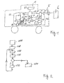
- FIG. 1 shows a schematic representation of a vehicle 1 with an internal combustion engine 2, which drives a generator 3. Furthermore, a battery 4 is provided, which is connected to an electrical connection 5. Instead of the battery 4, other types of electrical energy storage such as capacitors may be provided.
- the electrical connection 5 can be designed in the form of a plug to which an external power source 6 can be connected.
- the battery 4 may be connected via electrical lines directly or via a charger 7 to the terminal 5. In the embodiment in which the battery 4 is connected directly to the electrical connection 5, the charger 7 is arranged outside the vehicle 1.
- the battery 4 is connected via a first electrical line 8 and a first switch 9 to the generator 3 in connection. Furthermore, the battery 4 is connected via second electrical lines 10 with electrical consumers 11 of the vehicle 1 in connection.
- the electrical loads 11 are shown in the form of a block, wherein the electrical loads 11 are supplied via an electrical system of the vehicle from the battery 4 with power.
- the block in the FIG. 1 the electrical system of the vehicle is connected to the various electrical loads such as motors, switches, relays, control devices and / or bulbs.
- the generator 3 via a third electrical line 12 and a second switch 13 with the electrical loads 11, in particular with the electrical system of the vehicle 1, connected.
- the battery 4 is connected via a fourth electrical line 14 to a starter motor 15.
- the fourth electrical lead 14 may be connected to a second battery 16, which in turn communicates with the starter motor 15.
- the second battery 16 instead of the second battery 16 and capacitors, such as so-called supercapacitors, may be provided.
- the second battery 16 or the capacitors via a fifth electrical line 17 to the terminal 5 or, in the presence of the charger 7, be connected to the charger 7.
- the generator 3 may be connected via a sixth electrical line 24 and a third switch 25 to the second battery. Depending on the conduction state of the third switch 25, the generator 3 charges the second battery 16 or not.
- the vehicle 1 further has a control unit 18, which is connected via a first control line 19 to the first switch 9, via a second control line 20 to the second switch 13 and via a third control line 26 to the third switch 25.
- the control unit 18 via a sensor line 21 to the battery 4 and a second sensor line 22 connected to the second battery 16. With the aid of the sensor line 21, the control unit 18 detects the state of charge of the battery 4. Via the second sensor line 22, the control unit 18 detects the state of charge of the second battery 16.
- the generator 3 supplies the battery 4 with electricity and charges it.
- the generator 3 supplies the electrical load 11 or the vehicle electrical system of the vehicle with power.
- the starter 15 and the generator 3 may also be designed in the form of a starter generator.
- the starter 15 is used to start the engine 2.
- the generator 3 is driven by the engine 2 and is used to generate electricity.
- control unit 18 is connected to an output 23, via which information about the state of charge of the battery 4 and / or the second battery 16 can be displayed or output acoustically.
- control unit 18 may be connected to a navigation device which gives the control unit information about the route to be traveled to a destination and in particular information about the distance to a destination or to a charging location with an external power source.
- the charging location may be, for example, at home at the driver's residence.
- FIG. 2 shows a schematic sequence for operating the vehicle 1.
- the battery 4 and / or the second battery 16 are charged via the electrical connection 5 by means of an external power source 6.
- the charger 7 may be arranged in the vehicle or outside the vehicle.
- the energy transfer between the vehicle 1 and the external power supply 6 also contact without the help of an inductive energy transfer occur.
- the vehicle is started, ie, the internal combustion engine 2 is set by means of the starter motor 15 in operation, wherein the first, the second and third switches 9, 13, 25 are opened.
- the internal combustion engine 2 is operated, for example, by the control unit 18 or by a further control unit.
- the control unit 18 checks the state of charge of the battery 4 with the aid of the sensor line 21.
- the control unit 18 compares the current state of charge of the battery 4 with a threshold value.
- the threshold value is stored in a memory of the control unit 18. If the comparison at program point 140 reveals that the state of charge of the battery 4 is above the first threshold value, then the first and second switches 9, 13 remain open.
- the electrical consumers of the vehicle ie the electrical system of the vehicle powered by the battery 4 with electricity.
- a start-stop system of the internal combustion engine 2 is powered only by the battery 4 with power. This represents a first operating phase of the vehicle, which is shown in program item 150.
- the generator 3 can be used to power, for example, smaller consumers, in particular electrical actuators of the internal combustion engine 2, for example, injectors.
- a limit can be stored, which can also be adjustable.
- the generator 3 in the first phase of operation can supply no electrical consumers and no battery with electricity.
- the electrical system which includes essential electrical consumers of the vehicle 1, is supplied in the first operating state only by the battery 4 with power.
- the electrical loads 11 are supplied with power that has been charged from the external power source 6 into the battery 4.
- program item 150 the program branches back to program item 120.
- the program sequence 110 to 140 is run through until the state of charge of the battery 4 drops below the threshold value. This is detected in the query 140 by the controller 18, and it is branched to the program point 200.
- program point 200 which represents a second operating phase of the vehicle, the control unit 18 brings the first and the second switches 9, 13 into a closed position, so that the generator 3 both charges the battery 4 and also supplies the electrical consumers 11 with power.
- the control unit 18 may also close only one of the two switches 9, 13 in the second operating phase.
- the controller 18 and the third switch 24 is turned on. Subsequently, a branch is made back to program point 110. Furthermore, for example, in the second operating phase, a start / stop automatic of the separation motor 2 can be switched off.
- the controller 18 may adjust the threshold for the state of charge of the battery 4, over which the first operating phase and under which the second operating phase, depending on other parameters. For example, when determining the threshold value, a current maximum charge of the battery, which depends on the age of the battery, can be taken into account. In addition, the threshold value can be increased or decreased depending on information of a navigation device. For example, the threshold can be lowered when the vehicle is on the way to the next charging station and the distance is below a predetermined limit. Thus, in the knowledge that the next charging is only a certain distance away, a deeper discharge of the battery 4 are taken as given in purchasing.
- the state of charge of the battery can be estimated as a function of a charging voltage and of a charging current.
- the battery 4 when parking the vehicle not only from external energy sources, but also from internal power sources, such. B. from a vehicle-integrated solar roof with solar cells and / or a thermocouple that acts between vehicle interior and exterior space, are loaded.
- the battery 4 can be charged in all operating phases during braking of the vehicle via a corresponding coupling of the generator 3.
Abstract
Description
Die Erfindung betrifft ein Verfahren zum Betreiben einer elektrischen Versorgung von elektrischen Verbrauchern eines Fahrzeugs mit einem Verbrennungsmotor gemäß Patentanspruch 1 und ein elektrisches Versorgungssystem zum elektrischen Versorgen von elektrischen Verbrauchern eines Fahrzeugs mit Verbrennungsmotor gemäß Patentanspruch 9.The invention relates to a method for operating an electrical supply of electrical consumers of a vehicle with an internal combustion engine according to claim 1 and an electrical supply system for the electrical supply of electrical consumers of a vehicle with internal combustion engine according to claim 9.
Im Stand der Technik sind verschiedene Verfahren zum Betreiben von elektrischen Verbrauchern eines Fahrzeugs bekannt. Beispielsweise ist es bekannt, dass ein Generator eines Fahrzeugs eine Batterie des Fahrzeugs auflädt und damit elektrische Verbraucher, wie z.B. elektrische Antriebe, Steuergeräte oder elektrische Beleuchtungen, mit Strom versorgt werden.Various methods for operating electrical consumers of a vehicle are known in the prior art. For example, it is known that a generator of a vehicle charges a battery of the vehicle and thus electrical consumers, such as e.g. electric drives, control units or electric lighting, to be powered.
Weiterhin ist es bekannt, in Form eines Hybridantriebs ein Fahrzeug mit einem Verbrennungsmotor und einem Elektromotor bereitzustellen, wobei der Elektromotor von der Batterie mit Strom versorgt wird, wobei die Batterie vom Generator des Fahrzeugs aufgeladen wird. Zudem ist auch ein rein elektrischer Antrieb für ein Fahrzeug bekannt, bei dem die elektrischen Verbraucher des Fahrzeugs und der elektrische Antrieb mit Hilfe einer elektrischen Batterie mit Strom versorgt werden. Die Batterie wird über eine externe Stromquelle aufgeladen.Furthermore, it is known to provide in the form of a hybrid drive a vehicle with an internal combustion engine and an electric motor, wherein the electric motor is powered by the battery, wherein the battery is charged by the generator of the vehicle. In addition, a purely electric drive for a vehicle is known in which the electrical consumers of the vehicle and the electric drive with the help of an electric battery are powered. The battery is charged via an external power source.
Bei diesen Ansätzen wird wie bei einem reinen Elektrofahrzeug zusätzlich zum Generator und zur Batterie ein Elektromotor benötigt. Der Generator muss darüber hinaus ebenso wie die Batterie eine erhöhte Kapazität aufweisen.In these approaches, as in a pure electric vehicle, an electric motor is needed in addition to the generator and the battery. The generator must also have an increased capacity as well as the battery.
Weiterhin ist eine Lösung bekannt, bei der Bremsenergie des Fahrzeugs zurück gewonnen wird und in elektrische Energie umgewandelt wird.Furthermore, a solution is known in which the braking energy of the vehicle is recovered and converted into electrical energy.
Die Aufgabe der Erfindung besteht darin, einen neuen Ansatz für die Versorgung der elektrischen Verbraucher eines Fahrzeugs vorzusehen. Eine grundsätzliche Idee der Erfindung besteht darin, dass die elektrischen Verbraucher des Fahrzeugs weitestgehend unabhängig vom Generator mit Strom versorgt werden. Dies wird insbesondere dadurch erreicht, dass die elektrischen Verbraucher des Fahrzeugs im Wesentlichen von der Batterie mit Strom versorgt werden, so lange es der Ladezustand der Batterie zulässt. Weiterhin wird die Batterie soweit als möglich über eine externe oder interne Stromquelle aufgeladen. Dazu kann ein Ladegerät außerhalb oder im Fahrzeug vorgesehen sein. Sinkt der Ladezustand der Batterie unter einen Schwellwert, so werden die elektrischen Verbraucher vom Generator des Fahrzeugs mit Strom versorgt und/oder die Batterie vom Generator aufgeladen. Eine interne Stromquelle kann beispielsweise eine Solarzelle und/oder ein Thermoelement sein.The object of the invention is to provide a new approach to the supply of electrical consumers of a vehicle. A fundamental idea of the invention is that the electrical consumers of the vehicle are largely supplied with power independently of the generator. This is achieved, in particular, in that the electrical consumers of the vehicle are essentially supplied with power by the battery, as long as the state of charge of the battery allows it. Furthermore, the battery is charged as much as possible via an external or internal power source. For this purpose, a charger may be provided outside or in the vehicle. If the state of charge of the battery drops below a threshold value, the electrical consumers are supplied with power by the generator of the vehicle and / or the battery is charged by the generator. An internal power source may be, for example, a solar cell and / or a thermocouple.
Eine Grundidee besteht darin, dass die Batterie ihre Energie soweit als möglich über eine Ladevorrichtung von einer externen Stromversorgung bezieht. Die Ladevorrichtung kann beispielsweise in Form einer Steckdose oder einer induktiven Kopplung vorgesehen sein. Auf diese Weise ist eine Aufladung der Batterie ohne Wandlerverluste möglich. Zudem kann die Batterie des Fahrzeugs nach dem Anschließen an die externe Stromversorgung als elektrischer Puffer für ein Mikrokraftwerk dienen. So lange der Ladezustand der Batterie im Betrieb des Fahrzeugs sich in einem vordefinierten oder dynamisch definierten Bereich befinden, wird auf die Bereitstellung von elektrischer Energie durch den Verbrennungsmotor über den Generator verzichtet, d.h. die Versorgung mit elektrischem Strom erfolgt zunächst ohne weitere Wandelverluste aus der geladenen Batterie.A basic idea is that the battery draws its energy as much as possible from an external power supply via a charging device. The charging device may be provided for example in the form of a socket or an inductive coupling. In this way, a charge of the battery without transformer losses is possible. In addition, the battery of the vehicle after connecting to the external power supply can serve as an electric buffer for a micro-power plant. As long as the state of charge of the battery in the operation of the vehicle is in a predefined or dynamically defined area, the provision of electrical energy by the internal combustion engine via the generator is dispensed with, ie. The supply of electrical power is initially without further loss of conversion from the charged battery.
Versuche haben gezeigt, dass mit einer üblichen Batterie eines Fahrzeugs auf diese Weise bei Fahrstrecken von bis zu 60 km oder einer Betriebszeit von einer Stunde keine elektrische Energie vom Verbrennungsmotor über den Generator bereitgestellt werden muss. Somit ist dieser Ansatz der Energieversorgung auf Kurzstrecken und insbesondere im urbanen Umfeld von besonderem Interesse. Auf Kurzstrecken dürfte sich somit eine Kraftstoffeinsparung von 5% erreichen lassen. Weiterhin hat der neue Ansatz den Vorteil, dass ein schneller Übergang von bereits in Serie befindlichen Fahrzeugen mit geringen Zusatzkosten und geringem Entwicklungsrisiko auf das neue Konzept möglich ist. Zudem erfordert der neue Ansatz ein Minimum an neuen Komponenten (Kosten, Gewicht, Integration) und ein Minimum der Veränderungen am bestehenden Konzept.Experiments have shown that with a conventional battery of a vehicle in this way at distances of up to 60 km or an operating time of one hour, no electrical energy has to be provided by the internal combustion engine via the generator. Thus, this approach of energy supply on short distances and in particular in the urban environment is of particular interest. On short distances, fuel savings of 5% should be achieved. Furthermore, the new approach has the advantage that a rapid transition from already in series vehicles with low additional costs and low development risk on the new concept is possible. In addition, the new approach requires a minimum of new components (cost, weight, integration) and a minimum of changes to the existing concept.
Weiterhin können für die Bereitstellung der elektrischen Energie über das Aufladen der Batterie insbesondere regenerative Energiequellen wie Photovoltaik und Windenergie besser nutzbar gemacht werden, insbesondere in der Auslegung als Mikro-Kraftwerk. Diese Systeme speisen heute ins öffentliche Netz ein, wobei die Einspeisung jedoch Schwankungen im Bedarf unterliegt und die erzeugten Energiemengen zwischengespeichert oder bei Fehlen eines Speichers die Energieerzeugung eingestellt werden muss. Das Aufladen der Batterie kann beispielsweise in den Phasen einer geringen Nachfrage nach Strom im öffentlichen Netz erfolgen, wie beispielsweise nachts bei der Verwendung von Windkraftwerken. Zudem bietet die vorgeschlagene Lösung reduzierte Wandlerverluste, da die im Kraftstoff enthaltene chemische Energie nicht zuerst in eine mechanische Energie und dann in eine elektrische Energie mit Hilfe des Generators umgewandelt werden muss.Furthermore, in particular renewable energy sources such as photovoltaic and wind energy can be made more usable for the provision of electrical energy via the charging of the battery, in particular in the design as a micro-power plant. These systems feed into the public grid today, but the feed is subject to fluctuations in demand and the amount of energy generated must be cached or in the absence of a memory, the power must be set. The charging of the battery can be done, for example, in the phases of low demand for electricity in the public network, such as at night when using wind turbines. In addition, the proposed solution offers reduced transformer losses since the chemical energy contained in the fuel does not have to be first converted into mechanical energy and then into electrical energy by means of the generator.
Zu diesem Zweck erfolgt eine Aufladung der Batterie vor dem Start des Fahrzeugs nicht durch den Generator des Fahrzeugs, sondern durch externe Energiequellen. Der Begriff Batterie deckt dabei jede Art von aufladbarem Speicher für elektrische Energie, sowie auch mögliche Kombinationen von unterschiedlichen Speichern für elektrische Energie ab, wie z.B. eine normale Batterie (Akkumulator) für die Versorgung des elektrischen Bordnetzes des Fahrzeugs sowie eine zweite Batterie (Akkumulator) für Start bzw. Start-Stopp-Betrieb des Verbrennungsmotors oder z.B. einen oder mehrere ebenfalls aufgeladene Kondensatoren (super cap). Für die Beurteilung des Ladezustands können die aktuelle Ladung (SOC) der Batterie im Vergleich zur Maximalladung und/oder die aktuelle Maximalladung (SOH) berücksichtigt werden.For this purpose, a charge of the battery before the start of the vehicle is not by the generator of the vehicle, but by external energy sources. The term battery covers any type of rechargeable storage for electrical energy, as well as possible combinations of different storage for electrical energy, such as a normal battery (accumulator) for the supply of electrical Vehicle electrical system and a second battery (accumulator) for start or start-stop operation of the internal combustion engine or eg one or more also charged capacitors (super cap). For the assessment of the state of charge, the current charge (SOC) of the battery compared to the maximum charge and / or the current maximum charge (SOH) can be taken into account.
Solange der Ladezustand, insbesondere die prozentuale Maximalladung und/oder die aktuelle Maximalladung über vorgegebenen oder dynamisch definierten Grenzwerten liegen, wird auf eine Bereitstellung von elektrischer Energie durch den Verbrennungsmotor über den Generator verzichtet. Abhängig von der gewählten Ausführungsform könnten einzelne elektrische Verbraucher auch während der ersten Betriebsphase vom Generator mit Strom versorgt werden. Ziel ist es jedoch, die wesentliche Menge an elektrischer Energie über die Batterie bereitzustellen.As long as the state of charge, in particular the percentage maximum charge and / or the current maximum charge are above predefined or dynamically defined limits, provision is made for the provision of electrical energy by the internal combustion engine via the generator. Depending on the selected embodiment, individual electrical loads could be powered by the generator during the first phase of operation. The goal, however, is to provide the substantial amount of electrical energy through the battery.
Erst bei Unterschreiten des oder der Grenzwerte für den Ladezustand der Batterie wird der Generator dazu verwendet, um die elektrische Energie für das elektrische Bordnetz des Fahrzeugs und für ein elektrisches Aufladen der Batterie bereitzustellen.The generator is used only to provide the electrical energy for the electrical system of the vehicle and for an electrical charging of the battery when falling below the limit or state of charge for the battery.
In einer weiteren Ausführungsform wird in der ersten Betriebsphase des Fahrzeugs die Batterie nicht von dem Generator des Fahrzeugs aufgeladen.In a further embodiment, in the first operating phase of the vehicle, the battery is not charged by the generator of the vehicle.
In einer weiteren Ausführungsform werden in der ersten Betriebsphase die elektrischen Verbraucher des Fahrzeugs nur von der Batterie versorgt. Dadurch wird eine effiziente Ausnutzung der elektrischen Energie über die Batterie ermöglicht.In a further embodiment, the electrical consumers of the vehicle are supplied only by the battery in the first phase of operation. This allows efficient use of electrical energy through the battery.
In einer weiteren Ausführungsform wird der Ladezustand der Batterie durch eine gemessene Ladespannung und/oder einen gemessenen Ladestrom abgeschätzt. Dadurch ist eine einfache Abschätzung des Ladezustands der Batterie möglich.In a further embodiment, the state of charge of the battery is measured by a measured charging voltage and / or a measured Charging current estimated. This allows a simple estimation of the state of charge of the battery.
In einer weiteren Ausführungsform werden für die Durchführung eines automatischen Start/Stopp-Verfahrens zum Betreiben des Verbrennungsmotors eine zweite Batterie, beispielsweise Kondensatoren eingesetzt, die die elektrische Leistung zum Betreiben des Startermotors zum Starten eines Verbrennungsmotors bereitstellen. Die Kondensatoren werden vorzugsweise ebenfalls vor dem Start des Fahrzeugs über die externe Stromquelle aufgeladen.In a further embodiment, for carrying out an automatic start / stop method for operating the internal combustion engine, a second battery, for example, capacitors are used, which provide the electrical power for operating the starter motor for starting an internal combustion engine. The capacitors are also preferably charged via the external power source prior to starting the vehicle.
In einer weiteren Ausführungsform wird der Schwellwert für den Ladezustand der Batterie an ein Fahrszenario angepasst. Dazu kann beispielsweise berücksichtigt werden, ob sich das Fahrzeug auf einem Weg zu einer Ladestation befindet und somit der Weg bis zum nächsten externen Aufladen kürzer als eine vorgegebene Strecke ist. Somit kann bei einem Abstand des Fahrzeugs, der kleiner als die vorgegebene Strecke ist, der Schwellwert für den Ladezustand gesenkt werden, bis zu dem die Batterie entladen werden darf, bevor der Generator des Verbrennungsmotors zur elektrischen Versorgung der elektrischen Verbraucher und/oder zur Aufladung der Batterie verwendet wird.In a further embodiment, the threshold value for the state of charge of the battery is adapted to a driving scenario. For this purpose, for example, be taken into account whether the vehicle is on a way to a charging station and thus the way to the next external charging is shorter than a predetermined distance. Thus, at a distance of the vehicle, which is smaller than the predetermined distance, the threshold for the state of charge can be lowered, to which the battery may be discharged before the generator of the internal combustion engine for the electrical supply of the electrical loads and / or to charge the Battery is used.
In einer weiteren Ausführungsform wird bei Erreichen einer Ladegrenze der Batterie eine Ladeempfehlung im Fahrzeug angezeigt oder akustisch ausgegeben. Somit erhält der Fahrer den Hinweis, dass die Batterie über das externe Versorgungsnetz aufgeladen werden sollte. Die Ladegrenze kann größer oder gleich dem Schwellwert für den Ladezustand sein.In a further embodiment, upon reaching a charging limit of the battery, a charging recommendation is displayed in the vehicle or output acoustically. Thus, the driver receives the indication that the battery should be charged via the external supply network. The charging limit may be greater than or equal to the charge state threshold.
Zudem können weitere kraftstoffsparende Mittel, wie z.B. eine intelligente Routenerkennung, ein kraftstoffsparendes Powermanagement oder eine Energierückgewinnung und Aufladung der Batterie während einer Bremsung des Fahrzeugs verwendet werden. Beispielsweise könnte in einer Bremsphase eine zusätzliche Starterbatterie zum Antreiben des Starters des Verbrennungsmotors für Start/Stopp-Betrieb aufgeladen werden.In addition, other fuel-efficient means, such as intelligent route recognition, fuel-efficient power management or energy recovery and charging of the battery during vehicle braking may be used. For example, in a braking phase an additional Starter battery for driving the starter of the internal combustion engine for start / stop operation to be charged.
Die beschriebene Vorrichtung und das beschriebene Verfahren führen zu einer Reduktion des Spritverbrauchs, da kein zusätzlicher elektrischer Antrieb zur Ausnutzung einer elektrischen Energie vorgesehen ist. Daher werden gegenüber einem Hybridfahrzeug oder einem Elektrofahrzeug mechanischen und steuerungstechnische Integrationen in das Fahrzeug, d.h. Kosten und Gewicht, eingespart. Zudem sind aufgrund der externen Aufladung der Batterie elektrische Wandlerverluste reduziert. Weiterhin ist die Notwendigkeit zu einem Hochspannungsversorgungsnetz im Fahrzeug und der entsprechenden Verkabelung/Absicherung (z.B. Lichtbogenüberwachung) nicht gegeben. Zudem ist eine Änderung des Generators nicht erforderlich. Eine Markteinführung des beschriebenen Systems kann auf allen heutigen Plattformen schnell durchgeführt werden. Bei der Verwendung von 220 V Wechselspannung als Ladespannung für die externe Aufladung der Batterie kann eine rasche Marktdurchdringung erreicht werden. Eine Umwandlung des 220 V Wechselstrom zu 14 V Gleichstrom oder einer anderen Spannung kann im Fahrzeug oder an einer externen Ladestation durchgeführt werden. Zudem kann das Fahrzeug als elektrische Batterie für eine Pufferwirkung von Betreibern von Mikrokraftwerken eingesetzt werden.The device described and the method described lead to a reduction in fuel consumption, since no additional electric drive is provided for the utilization of electrical energy. Therefore, in relation to a hybrid vehicle or an electric vehicle, mechanical and control-related integrations into the vehicle, i. Cost and weight, saved. In addition, electrical transformer losses are reduced due to the external charging of the battery. Furthermore, there is no need for a high voltage power supply in the vehicle and the appropriate wiring / fusing (e.g., arc monitoring). In addition, a change of the generator is not required. A market launch of the system described can be carried out quickly on all platforms today. When using 220 V AC as the charging voltage for the external charging of the battery rapid market penetration can be achieved. A conversion from 220 V AC to 14 V DC or other voltage can be performed in the vehicle or at an external charging station. In addition, the vehicle can be used as an electric battery for a buffer effect of operators of micro-power plants.
Mit dem beschriebenen System wird zu geringeren Kosten und bei geringem technischem Aufwand eine Alternative zu Hybridfahrzeugen bereitgestellt. Das beschriebene elektrische Versorgungssystem zum Versorgen von elektrischen Verbrauchern eines Fahrzeugs mit einem Verbrennungsmotor weist eine Batterie auf, wobei die Batterie mit Hilfe einer außerhalb des Fahrzeugs befindlichen Stromquelle aufladbar ist. Das Versorgungssystem umfasst ein Steuergerät, das ausgebildet ist, um während einer ersten Betriebsphase des Fahrzeugs, in der ein Ladezustand der Batterie über einem Schwellwert liegt, eine elektrische Versorgung der elektrischen Verbraucher im Wesentlichen über die Batterie festzulegen. Zudem wird bei Absinken des Ladezustands der Batterie unter den Schwellwert eine zweite Betriebsphase des Fahrzeugs begonnen, wobei in der zweiten Betriebsphase das Steuergerät ausgebildet ist, um die Batterie vom Generator aufladen zu lassen und/oder die elektrischen Verbraucher des Fahrzeugs vom Generator mit Strom zu versorgen.With the described system, an alternative to hybrid vehicles is provided at a lower cost and with less technical effort. The described electrical supply system for supplying electrical consumers of a vehicle with an internal combustion engine has a battery, wherein the battery is rechargeable by means of a power source located outside the vehicle. The supply system comprises a control device, which is designed to substantially supply an electrical supply to the electrical consumers during a first operating phase of the vehicle in which a charge state of the battery is above a threshold value via the battery. In addition, when the state of charge of the battery drops below the threshold value, a second operating phase of the vehicle is started, wherein in the second operating phase the control unit is designed to charge the battery from the generator and / or to supply the electric consumers of the vehicle with electricity from the generator ,
Abhängig von der gewählten Ausführungsform kann ein Ladegerät im Fahrzeug angeordnet sein.Depending on the chosen embodiment, a charger may be located in the vehicle.
Vorzugsweise ist der Anschluss als induktives Koppelelement zur Übertragung von elektrischer Leistung ausgebildet.Preferably, the terminal is designed as an inductive coupling element for the transmission of electrical power.
Die Erfindung wird im Folgenden anhand der Figuren näher erläutert. Es zeigen:
-
Figur 1 eine schematische Darstellung eines Fahrzeugs; und -
Figur 2
-
FIG. 1 a schematic representation of a vehicle; and -
FIG. 2 a schematic representation of a process flow.
Die Batterie 4 steht über eine erste elektrische Leitung 8 und einen ersten Schalter 9 mit dem Generator 3 in Verbindung. Weiterhin steht die Batterie 4 über zweite elektrische Leitungen 10 mit elektrischen Verbrauchern 11 des Fahrzeugs 1 in Verbindung. Die elektrischen Verbraucher 11 sind in Form eines Blocks dargestellt, wobei die elektrischen Verbraucher 11 über ein Bordnetz des Fahrzeugs von der Batterie 4 mit Strom versorgt werden. Somit stellt der Block in der
Das Fahrzeug 1 verfügt weiterhin über ein Steuergerät 18, das über eine erste Steuerleitung 19 mit dem ersten Schalter 9, über eine zweite Steuerleitung 20 mit dem zweiten Schalter 13 und über eine dritte Steuerleitung 26 mit dem dritten Schalter 25 verbunden ist. Zudem ist das Steuergerät 18 über eine Sensorleitung 21 mit der Batterie 4 und über eine zweite Sensorleitung 22 mit der zweiten Batterie 16 verbunden. Mit Hilfe der Sensorleitung 21 erfasst das Steuergerät 18 den Ladezustand der Batterie 4. Über die zweite Sensorleitung 22 erfasst das Steuergerät 18 den Ladezustand der zweiten Batterie 16. Abhängig von dem Öffnungs- bzw. Schließzustand des ersten Schalters 1 versorgt der Generator 3 die Batterie 4 mit Strom und lädt diese auf. Abhängig von dem Schalt- bzw. Öffnungszustand des zweiten Schalters 13 versorgt der Generator 3 die elektrischen Verbraucher 11 bzw. das Bordnetz des Fahrzeugs mit Strom. Abhängig von der gewählten Ausführungsform können der Starter 15 und der Generator 3 auch in Form eines Startergenerators ausgebildet sein. Der Starter 15 dient zum Starten des Verbrennungsmotors 2. Der Generator 3 wird vom Verbrennungsmotor 2 angetrieben und dient zur Erzeugung von Strom.The vehicle 1 further has a control unit 18, which is connected via a
Abhängig von der gewählten Ausführungsform ist das Steuergerät 18 mit einer Ausgabe 23 verbunden, über die Informationen über den Ladezustand der Batterie 4 und/oder der zweiten Batterie 16 angezeigt bzw. akustisch ausgegeben werden können.Depending on the selected embodiment, the control unit 18 is connected to an
Weiterhin kann das Steuergerät 18 mit einem Navigationsgerät verbunden sein, das dem Steuergerät Informationen über die zu fahrende Route zu einem Ziel und insbesondere Informationen über die Entfernung bis zu einem Ziel bzw. bis zu einem Ladestandort mit einer externen Stromquelle gibt. Der Ladestandort kann beispielsweise zu Hause am Wohnort des Fahrers sein.Furthermore, the control unit 18 may be connected to a navigation device which gives the control unit information about the route to be traveled to a destination and in particular information about the distance to a destination or to a charging location with an external power source. The charging location may be, for example, at home at the driver's residence.
In diesem Zustand kann der Generator 3 dazu verwendet werden, um beispielsweise kleinere Verbraucher, insbesondere elektrische Stellglieder des Verbrennungsmotors 2, beispielsweise Einspritzventile, mit Strom zu versorgen. Für die Einleitung in kleine und große elektrische Verbraucher kann ein Grenzwert abgelegt sein, der auch einstellbar sein kann. Abhängig von der Ausführungsform kann der Generator 3 in der ersten Betriebsphase keine elektrischen Verbraucher und keine Batterie mit Strom versorgen. Das Bordnetz jedoch, das wesentliche elektrische Verbraucher des Fahrzeugs 1 umfasst, wird im ersten Betriebszustand nur von der Batterie 4 mit Strom versorgt. Somit werden im ersten Betriebszustand die elektrischen Verbraucher 11 mit Strom dem versorgt, der von der externen Stromquelle 6 in die Batterie 4 geladen wurde.In this state, the
Nach dem Programmpunkt 150 wird zum Programmpunkt 120 zurück verzweigt. Der Programmablauf 110 bis 140 wird so oft durchlaufen, bis der Ladezustand der Batterie 4 unter den Schwellwert sinkt. Dies wird bei der Abfrage 140 vom Steuergerät 18 erkannt, und es wird zum Programmpunkt 200 verzweigt. Beim Programmpunkt 200, der eine zweite Betriebsphase des Fahrzeugs darstellt, werden vom Steuergerät 18 der erste und der zweite Schalter 9, 13 in eine Schließstellung gebracht, so dass der Generator 3 sowohl die Batterie 4 auflädt als auch die elektrischen Verbraucher 11 mit Strom versorgt. Abhängig von der gewählten Ausführungsform kann das Steuergerät 18 in der zweiten Betriebsphase auch nur einen der zwei Schalter 9, 13 schließen. Zudem wird vom Steuergerät 18 auch der dritte Schalter 24 leitend geschaltet. Anschließend wird zu Programmpunkt 110 zurück verzweigt. Weiterhin kann beispielsweise in der zweiten Betriebsphase eine Start/Stopp Automatik des Vertrennungsmotors 2 ausgeschaltet werden.After
Abhängig von der gewählten Ausführungsform kann das Steuergerät 18 den Schwellwert für den Ladezustand der Batterie 4, über dem die erste Betriebsphase und unter dem die zweite Betriebsphase vorliegt, abhängig von weiteren Parametern anpassen. Beispielsweise kann bei der Ermittlung des Schwellwerts eine aktuelle maximale Ladung der Batterie, die vom Alter der Batterie abhängt, berücksichtigt werden. Zudem kann der Schwellwert abhängig von Informationen eines Navigationsgeräts erhöht oder abgesenkt werden. Beispielsweise kann der Schwellwert abgesenkt werden, wenn sich das Fahrzeug auf dem Weg zur nächsten Ladestation befindet und die Entfernung unter einem vorgegebenen Grenzwert liegt. Somit kann im Wissen, dass der nächste Ladevorgang nur eine bestimmte Fahrstrecke entfernt liegt, eine tiefere Entladung der Batterie 4 als vorgegeben in Kauf genommen werden.Depending on the selected embodiment, the controller 18 may adjust the threshold for the state of charge of the battery 4, over which the first operating phase and under which the second operating phase, depending on other parameters. For example, when determining the threshold value, a current maximum charge of the battery, which depends on the age of the battery, can be taken into account. In addition, the threshold value can be increased or decreased depending on information of a navigation device. For example, the threshold can be lowered when the vehicle is on the way to the next charging station and the distance is below a predetermined limit. Thus, in the knowledge that the next charging is only a certain distance away, a deeper discharge of the battery 4 are taken as given in purchasing.
In einer weiteren Ausführungsform kann der Ladezustand der Batterie abhängig von einer Ladespannung und von einem Ladestrom abgeschätzt werden.In a further embodiment, the state of charge of the battery can be estimated as a function of a charging voltage and of a charging current.
In einer weiteren Ausführungsform kann die Batterie 4 beim Parken des Fahrzeuges nicht nur von externen Energiequellen, sondern auch von internen Stromquellen, wie z. B. von einem im Fahrzeug integrierten Solardach mit Solarzellen und/oder einem Thermoelement, das zwischen Fahrzeuginnen- und Außenraum wirkt, geladen werden.In a further embodiment, the battery 4 when parking the vehicle not only from external energy sources, but also from internal power sources, such. B. from a vehicle-integrated solar roof with solar cells and / or a thermocouple that acts between vehicle interior and exterior space, are loaded.
Weiterhin kann die Batterie 4 in allen Betriebsphasen während des Bremsens des Fahrzeugs über eine entsprechende Kopplung des Generators 3 aufgeladen werden.Furthermore, the battery 4 can be charged in all operating phases during braking of the vehicle via a corresponding coupling of the
- 11
- Fahrzeugvehicle
- 22
- Verbrennungsmotorinternal combustion engine
- 33
- Generatorgenerator
- 44
- Batteriebattery
- 55
- Anschlussconnection
- 66
- Stromquellepower source
- 77
- Ladegerätcharger
- 88th
- erste elektrische Leitungfirst electrical line
- 99
- erster Schalterfirst switch
- 1010
- zweite elektrische Leitungsecond electrical line
- 1111
- elektrischer Verbraucherelectrical consumer
- 1212
- dritte elektrische Leitungthird electrical line
- 1313
- zweiter Schaltersecond switch
- 1414
- vierte elektrische Leitungfourth electrical line
- 1515
- Startermotorstarter motor
- 1616
- zweite Batteriesecond battery
- 1717
- fünfte elektrische Leitungfifth electrical line
- 1818
- Steuergerätcontrol unit
- 1919
- erste Steuerleitungfirst control line
- 2020
- zweite Steuerleitungsecond control line
- 2121
- Sensorleitungsensor line
- 2222
- zweite Sensorleitungsecond sensor line
- 2323
- Ausgabeoutput
- 2424
- sechste elektrische Leitungsixth electrical line
- 2525
- dritter Schalterthird switch
- 2626
- dritte Steuerleitungthird control line
Claims (10)
Applications Claiming Priority (1)
| Application Number | Priority Date | Filing Date | Title |
|---|---|---|---|
| DE102011080427A DE102011080427A1 (en) | 2011-08-04 | 2011-08-04 | Electric supply system for a vehicle |
Publications (2)
| Publication Number | Publication Date |
|---|---|
| EP2554424A2 true EP2554424A2 (en) | 2013-02-06 |
| EP2554424A3 EP2554424A3 (en) | 2016-10-12 |
Family
ID=47172234
Family Applications (1)
| Application Number | Title | Priority Date | Filing Date |
|---|---|---|---|
| EP12179067.9A Ceased EP2554424A3 (en) | 2011-08-04 | 2012-08-02 | Electricity supplysystem for vehicle |
Country Status (2)
| Country | Link |
|---|---|
| EP (1) | EP2554424A3 (en) |
| DE (1) | DE102011080427A1 (en) |
Cited By (2)
| Publication number | Priority date | Publication date | Assignee | Title |
|---|---|---|---|---|
| CN103950417A (en) * | 2014-05-15 | 2014-07-30 | 天津永明新能源科技有限公司 | Wind-light complementary power generation device special for automobile |
| CN111497629A (en) * | 2019-12-12 | 2020-08-07 | 郭林 | Electric automobile and power supply control method |
Families Citing this family (1)
| Publication number | Priority date | Publication date | Assignee | Title |
|---|---|---|---|---|
| DE102013112678A1 (en) * | 2013-11-18 | 2015-05-21 | Dr. Ing. H.C. F. Porsche Aktiengesellschaft | Method for controlling a state of charge of a battery of a vehicle electrical system |
Family Cites Families (19)
| Publication number | Priority date | Publication date | Assignee | Title |
|---|---|---|---|---|
| US4489242A (en) * | 1981-01-22 | 1984-12-18 | Worst Marc T | Stored power system for vehicle accessories |
| JPH0988778A (en) * | 1995-07-17 | 1997-03-31 | Denso Corp | Starter generator |
| FR2749991B1 (en) * | 1996-06-14 | 1998-08-07 | Siemens Automotive Sa | METHOD AND DEVICE FOR CONTROLLING A MOTOR VEHICLE ALTERNATOR |
| US6166523A (en) * | 2000-01-11 | 2000-12-26 | Honeywell International Inc. | Smart alternator method and apparatus for optimizing fuel efficiency and monitoring batteries in an automobile |
| DE102004021317A1 (en) * | 2004-04-30 | 2005-11-24 | S-Y Systems Technologies Europe Gmbh | On-board network and switch for a vehicle electrical system |
| JP2005348576A (en) * | 2004-06-07 | 2005-12-15 | Auto Network Gijutsu Kenkyusho:Kk | Battery management device and method |
| JP2006230132A (en) * | 2005-02-18 | 2006-08-31 | Honda Motor Co Ltd | Current supply method, starting method of internal combustion engine, power supply and vehicle |
| CN101218119B (en) * | 2005-05-05 | 2011-01-12 | Afs三一电力公司 | Hybrid electric vehicle power train |
| JP2007008349A (en) * | 2005-06-30 | 2007-01-18 | Yamaha Motor Co Ltd | Hybrid vehicle |
| DE102005046340B4 (en) * | 2005-09-28 | 2012-04-19 | Audi Ag | A method for setting an operating state of consumers of an energy system as needed in a vehicle with a start / stop system |
| DE102006002985A1 (en) * | 2006-01-21 | 2007-08-09 | Bayerische Motoren Werke Ag | Energy storage system for a motor vehicle |
| US7692412B2 (en) * | 2006-02-20 | 2010-04-06 | Fujitsu Ten Limited | Charging control apparatus, charging control method |
| DE102006036425A1 (en) * | 2006-08-04 | 2008-02-07 | Bayerische Motoren Werke Ag | System for supplying power to electrical consumers of a motor vehicle |
| DE102007003005A1 (en) * | 2007-01-20 | 2008-02-28 | Audi Ag | Battery system for use in motor vehicle, has control devices for controlling access system when engine of vehicle is stopped and supplied with energy through starter battery independent of charge condition of main power supply battery |
| DE102008017685A1 (en) * | 2008-04-08 | 2008-12-11 | Daimler Ag | Battery i.e. motor vehicle battery, condition determining and displaying method, involves comparing state of charge with threshold value, and displaying request for charging battery by display unit during permanent shortfall of value |
| DE102008062203A1 (en) * | 2008-12-13 | 2010-06-17 | Daimler Ag | Electrical system for car, has diode that is controllable by monitoring unit such that energy flow directed from auxiliary energy memory to energy storage is interrupted during starting of engine or during operation of engine |
| JP5413042B2 (en) * | 2009-08-07 | 2014-02-12 | 株式会社デンソー | Storage information output device and storage information output system |
| DE102009058895A1 (en) * | 2009-12-18 | 2010-08-05 | Daimler Ag | Motor vehicle generator controlling and/or regulating device, has controlling and/or regulating device designed, such that consumption-reducing actions of generator management system are inoperable when starting scenario is detected |
| DE102010000679A1 (en) * | 2010-01-05 | 2011-07-07 | Robert Bosch GmbH, 70469 | Method for detecting startability |
-
2011
- 2011-08-04 DE DE102011080427A patent/DE102011080427A1/en not_active Ceased
-
2012
- 2012-08-02 EP EP12179067.9A patent/EP2554424A3/en not_active Ceased
Non-Patent Citations (1)
| Title |
|---|
| None |
Cited By (2)
| Publication number | Priority date | Publication date | Assignee | Title |
|---|---|---|---|---|
| CN103950417A (en) * | 2014-05-15 | 2014-07-30 | 天津永明新能源科技有限公司 | Wind-light complementary power generation device special for automobile |
| CN111497629A (en) * | 2019-12-12 | 2020-08-07 | 郭林 | Electric automobile and power supply control method |
Also Published As
| Publication number | Publication date |
|---|---|
| DE102011080427A1 (en) | 2013-02-07 |
| EP2554424A3 (en) | 2016-10-12 |
Similar Documents
| Publication | Publication Date | Title |
|---|---|---|
| DE102013221634B4 (en) | Method and system for charging a plug-in electric vehicle | |
| EP1593188B1 (en) | Device for supplying power to a two-voltage vehicle electric system | |
| DE102019102998A1 (en) | ONBOARD DC CHARGING USING TRACTION DRIVE COMPONENTS | |
| EP2528766B1 (en) | Battery system for micro-hybrid vehicles comprising high-efficiency consumers | |
| EP2387524B1 (en) | Onboard network and voltage transformer for a vehicle and method for controlling a multi-voltage on-board network | |
| EP2822808B1 (en) | On-board power system for a vehicle | |
| WO2002087068A1 (en) | Device for power supply in a multi-voltage electric system of a motor vehicle | |
| DE102007026164A1 (en) | Electrical supply system for motor vehicle, has battery charging ultra cap by direct current-direct current converter before start of vehicle on high stress than rated stress, where stress level of electrical system is determined | |
| DE112013007089T5 (en) | Charge control device using a vehicle-side solar cell | |
| DE102015108789A1 (en) | Energy supply system for a motor vehicle | |
| EP3616295A1 (en) | Circuit and charging method for an electrical energy storage system | |
| DE10213105A1 (en) | Drive for a motor vehicle | |
| DE102014016620A1 (en) | Method for operating an energy storage device in a motor vehicle and motor vehicle | |
| DE102011109709A1 (en) | Method for voltage supply to on-board network of e.g. motor car, involves interrupting connection between primary energy storage unit and on-board network based on a ratio of direct current voltages of energy storage units | |
| DE102014201362A1 (en) | Method for operating a vehicle electrical system | |
| DE102007004279A1 (en) | Multi-voltage vehicle electrical system for a motor vehicle | |
| EP2670974B1 (en) | Jump start device for a motor vehicle | |
| DE102010062362A1 (en) | High-speed charging station for charging battery of electric vehicle, has output-side converter with high output power, whose input and output terminals are connected to respective electrical energy storage device and electrical load | |
| EP2528767B1 (en) | Battery system for micro-hybrid vehicles comprising high-efficiency consumers | |
| WO2015172924A1 (en) | Device and method for charging two energy stores | |
| EP3079941A1 (en) | Precharging an electric dc link storage element | |
| DE102021100443A1 (en) | UNIFORM ON-BOARD CHARGER AND GENERATOR FOR ONE VEHICLE | |
| DE102007014383A1 (en) | Multi-voltage vehicle electrical system for motor vehicle, has multi-voltage generator, whose energy is supplied over controllable switching device in either of two energy storage | |
| DE102012007158A1 (en) | Device for controlling power flow in motor vehicle e.g. motor car, has switching device that separates electric drive from bidirectionally operable inverter and connects inverter with charging terminal device based on control signal | |
| WO2004006422A1 (en) | Automotive on-board supply system |
Legal Events
| Date | Code | Title | Description |
|---|---|---|---|
| PUAI | Public reference made under article 153(3) epc to a published international application that has entered the european phase |
Free format text: ORIGINAL CODE: 0009012 |
|
| AK | Designated contracting states |
Kind code of ref document: A2 Designated state(s): AL AT BE BG CH CY CZ DE DK EE ES FI FR GB GR HR HU IE IS IT LI LT LU LV MC MK MT NL NO PL PT RO RS SE SI SK SM TR |
|
| AX | Request for extension of the european patent |
Extension state: BA ME |
|
| PUAL | Search report despatched |
Free format text: ORIGINAL CODE: 0009013 |
|
| AK | Designated contracting states |
Kind code of ref document: A3 Designated state(s): AL AT BE BG CH CY CZ DE DK EE ES FI FR GB GR HR HU IE IS IT LI LT LU LV MC MK MT NL NO PL PT RO RS SE SI SK SM TR |
|
| AX | Request for extension of the european patent |
Extension state: BA ME |
|
| RIC1 | Information provided on ipc code assigned before grant |
Ipc: B60W 10/26 20060101ALI20160906BHEP Ipc: B60L 11/12 20060101ALI20160906BHEP Ipc: B60R 16/03 20060101ALI20160906BHEP Ipc: B60W 10/08 20060101ALI20160906BHEP Ipc: B60W 10/30 20060101ALI20160906BHEP Ipc: H02J 7/00 20060101ALI20160906BHEP Ipc: B60L 1/00 20060101AFI20160906BHEP Ipc: H02J 7/14 20060101ALI20160906BHEP |
|
| STAA | Information on the status of an ep patent application or granted ep patent |
Free format text: STATUS: REQUEST FOR EXAMINATION WAS MADE |
|
| 17P | Request for examination filed |
Effective date: 20170411 |
|
| RBV | Designated contracting states (corrected) |
Designated state(s): AL AT BE BG CH CY CZ DE DK EE ES FI FR GB GR HR HU IE IS IT LI LT LU LV MC MK MT NL NO PL PT RO RS SE SI SK SM TR |
|
| STAA | Information on the status of an ep patent application or granted ep patent |
Free format text: STATUS: EXAMINATION IS IN PROGRESS |
|
| 17Q | First examination report despatched |
Effective date: 20171115 |
|
| STAA | Information on the status of an ep patent application or granted ep patent |
Free format text: STATUS: EXAMINATION IS IN PROGRESS |
|
| STAA | Information on the status of an ep patent application or granted ep patent |
Free format text: STATUS: THE APPLICATION HAS BEEN REFUSED |
|
| 18R | Application refused |
Effective date: 20200924 |