EP2554424A2 - Système de allimentation électrique pour vehicule - Google Patents
Système de allimentation électrique pour vehicule Download PDFInfo
- Publication number
- EP2554424A2 EP2554424A2 EP12179067A EP12179067A EP2554424A2 EP 2554424 A2 EP2554424 A2 EP 2554424A2 EP 12179067 A EP12179067 A EP 12179067A EP 12179067 A EP12179067 A EP 12179067A EP 2554424 A2 EP2554424 A2 EP 2554424A2
- Authority
- EP
- European Patent Office
- Prior art keywords
- battery
- vehicle
- electrical
- generator
- charge
- Prior art date
- Legal status (The legal status is an assumption and is not a legal conclusion. Google has not performed a legal analysis and makes no representation as to the accuracy of the status listed.)
- Ceased
Links
- 230000005611 electricity Effects 0.000 title claims description 8
- 238000002485 combustion reaction Methods 0.000 claims abstract description 23
- 238000000034 method Methods 0.000 claims abstract description 15
- 239000007858 starting material Substances 0.000 claims description 11
- 230000007423 decrease Effects 0.000 claims 2
- 239000003990 capacitor Substances 0.000 description 6
- 238000013459 approach Methods 0.000 description 5
- 230000008878 coupling Effects 0.000 description 3
- 238000010168 coupling process Methods 0.000 description 3
- 238000005859 coupling reaction Methods 0.000 description 3
- 239000000446 fuel Substances 0.000 description 3
- 230000001939 inductive effect Effects 0.000 description 3
- 238000006243 chemical reaction Methods 0.000 description 2
- 230000010354 integration Effects 0.000 description 2
- 238000012546 transfer Methods 0.000 description 2
- 230000008901 benefit Effects 0.000 description 1
- 230000005540 biological transmission Effects 0.000 description 1
- 230000008859 change Effects 0.000 description 1
- 230000003247 decreasing effect Effects 0.000 description 1
- 238000013461 design Methods 0.000 description 1
- 238000011161 development Methods 0.000 description 1
- 230000000694 effects Effects 0.000 description 1
- 238000004146 energy storage Methods 0.000 description 1
- 238000002474 experimental method Methods 0.000 description 1
- 230000006870 function Effects 0.000 description 1
- 238000012544 monitoring process Methods 0.000 description 1
- 230000035515 penetration Effects 0.000 description 1
- 230000008569 process Effects 0.000 description 1
- 238000011084 recovery Methods 0.000 description 1
- 230000009467 reduction Effects 0.000 description 1
- 238000000926 separation method Methods 0.000 description 1
- 239000000126 substance Substances 0.000 description 1
- 230000007704 transition Effects 0.000 description 1
Images
Classifications
-
- B—PERFORMING OPERATIONS; TRANSPORTING
- B60—VEHICLES IN GENERAL
- B60L—PROPULSION OF ELECTRICALLY-PROPELLED VEHICLES; SUPPLYING ELECTRIC POWER FOR AUXILIARY EQUIPMENT OF ELECTRICALLY-PROPELLED VEHICLES; ELECTRODYNAMIC BRAKE SYSTEMS FOR VEHICLES IN GENERAL; MAGNETIC SUSPENSION OR LEVITATION FOR VEHICLES; MONITORING OPERATING VARIABLES OF ELECTRICALLY-PROPELLED VEHICLES; ELECTRIC SAFETY DEVICES FOR ELECTRICALLY-PROPELLED VEHICLES
- B60L1/00—Supplying electric power to auxiliary equipment of vehicles
-
- B—PERFORMING OPERATIONS; TRANSPORTING
- B60—VEHICLES IN GENERAL
- B60L—PROPULSION OF ELECTRICALLY-PROPELLED VEHICLES; SUPPLYING ELECTRIC POWER FOR AUXILIARY EQUIPMENT OF ELECTRICALLY-PROPELLED VEHICLES; ELECTRODYNAMIC BRAKE SYSTEMS FOR VEHICLES IN GENERAL; MAGNETIC SUSPENSION OR LEVITATION FOR VEHICLES; MONITORING OPERATING VARIABLES OF ELECTRICALLY-PROPELLED VEHICLES; ELECTRIC SAFETY DEVICES FOR ELECTRICALLY-PROPELLED VEHICLES
- B60L50/00—Electric propulsion with power supplied within the vehicle
- B60L50/10—Electric propulsion with power supplied within the vehicle using propulsion power supplied by engine-driven generators, e.g. generators driven by combustion engines
- B60L50/15—Electric propulsion with power supplied within the vehicle using propulsion power supplied by engine-driven generators, e.g. generators driven by combustion engines with additional electric power supply
-
- B—PERFORMING OPERATIONS; TRANSPORTING
- B60—VEHICLES IN GENERAL
- B60W—CONJOINT CONTROL OF VEHICLE SUB-UNITS OF DIFFERENT TYPE OR DIFFERENT FUNCTION; CONTROL SYSTEMS SPECIALLY ADAPTED FOR HYBRID VEHICLES; ROAD VEHICLE DRIVE CONTROL SYSTEMS FOR PURPOSES NOT RELATED TO THE CONTROL OF A PARTICULAR SUB-UNIT
- B60W10/00—Conjoint control of vehicle sub-units of different type or different function
- B60W10/04—Conjoint control of vehicle sub-units of different type or different function including control of propulsion units
- B60W10/06—Conjoint control of vehicle sub-units of different type or different function including control of propulsion units including control of combustion engines
-
- B—PERFORMING OPERATIONS; TRANSPORTING
- B60—VEHICLES IN GENERAL
- B60W—CONJOINT CONTROL OF VEHICLE SUB-UNITS OF DIFFERENT TYPE OR DIFFERENT FUNCTION; CONTROL SYSTEMS SPECIALLY ADAPTED FOR HYBRID VEHICLES; ROAD VEHICLE DRIVE CONTROL SYSTEMS FOR PURPOSES NOT RELATED TO THE CONTROL OF A PARTICULAR SUB-UNIT
- B60W10/00—Conjoint control of vehicle sub-units of different type or different function
- B60W10/30—Conjoint control of vehicle sub-units of different type or different function including control of auxiliary equipment, e.g. air-conditioning compressors or oil pumps
-
- B—PERFORMING OPERATIONS; TRANSPORTING
- B60—VEHICLES IN GENERAL
- B60W—CONJOINT CONTROL OF VEHICLE SUB-UNITS OF DIFFERENT TYPE OR DIFFERENT FUNCTION; CONTROL SYSTEMS SPECIALLY ADAPTED FOR HYBRID VEHICLES; ROAD VEHICLE DRIVE CONTROL SYSTEMS FOR PURPOSES NOT RELATED TO THE CONTROL OF A PARTICULAR SUB-UNIT
- B60W30/00—Purposes of road vehicle drive control systems not related to the control of a particular sub-unit, e.g. of systems using conjoint control of vehicle sub-units
- B60W30/18—Propelling the vehicle
- B60W30/188—Controlling power parameters of the driveline, e.g. determining the required power
- B60W30/1886—Controlling power supply to auxiliary devices
-
- H—ELECTRICITY
- H02—GENERATION; CONVERSION OR DISTRIBUTION OF ELECTRIC POWER
- H02J—CIRCUIT ARRANGEMENTS OR SYSTEMS FOR SUPPLYING OR DISTRIBUTING ELECTRIC POWER; SYSTEMS FOR STORING ELECTRIC ENERGY
- H02J7/00—Circuit arrangements for charging or depolarising batteries or for supplying loads from batteries
- H02J7/0063—Circuit arrangements for charging or depolarising batteries or for supplying loads from batteries with circuits adapted for supplying loads from the battery
-
- H—ELECTRICITY
- H02—GENERATION; CONVERSION OR DISTRIBUTION OF ELECTRIC POWER
- H02J—CIRCUIT ARRANGEMENTS OR SYSTEMS FOR SUPPLYING OR DISTRIBUTING ELECTRIC POWER; SYSTEMS FOR STORING ELECTRIC ENERGY
- H02J7/00—Circuit arrangements for charging or depolarising batteries or for supplying loads from batteries
- H02J7/007—Regulation of charging or discharging current or voltage
- H02J7/00712—Regulation of charging or discharging current or voltage the cycle being controlled or terminated in response to electric parameters
-
- H—ELECTRICITY
- H02—GENERATION; CONVERSION OR DISTRIBUTION OF ELECTRIC POWER
- H02J—CIRCUIT ARRANGEMENTS OR SYSTEMS FOR SUPPLYING OR DISTRIBUTING ELECTRIC POWER; SYSTEMS FOR STORING ELECTRIC ENERGY
- H02J7/00—Circuit arrangements for charging or depolarising batteries or for supplying loads from batteries
- H02J7/14—Circuit arrangements for charging or depolarising batteries or for supplying loads from batteries for charging batteries from dynamo-electric generators driven at varying speed, e.g. on vehicle
- H02J7/1446—Circuit arrangements for charging or depolarising batteries or for supplying loads from batteries for charging batteries from dynamo-electric generators driven at varying speed, e.g. on vehicle in response to parameters of a vehicle
-
- B—PERFORMING OPERATIONS; TRANSPORTING
- B60—VEHICLES IN GENERAL
- B60W—CONJOINT CONTROL OF VEHICLE SUB-UNITS OF DIFFERENT TYPE OR DIFFERENT FUNCTION; CONTROL SYSTEMS SPECIALLY ADAPTED FOR HYBRID VEHICLES; ROAD VEHICLE DRIVE CONTROL SYSTEMS FOR PURPOSES NOT RELATED TO THE CONTROL OF A PARTICULAR SUB-UNIT
- B60W2510/00—Input parameters relating to a particular sub-units
- B60W2510/24—Energy storage means
- B60W2510/242—Energy storage means for electrical energy
- B60W2510/244—Charge state
-
- Y—GENERAL TAGGING OF NEW TECHNOLOGICAL DEVELOPMENTS; GENERAL TAGGING OF CROSS-SECTIONAL TECHNOLOGIES SPANNING OVER SEVERAL SECTIONS OF THE IPC; TECHNICAL SUBJECTS COVERED BY FORMER USPC CROSS-REFERENCE ART COLLECTIONS [XRACs] AND DIGESTS
- Y02—TECHNOLOGIES OR APPLICATIONS FOR MITIGATION OR ADAPTATION AGAINST CLIMATE CHANGE
- Y02T—CLIMATE CHANGE MITIGATION TECHNOLOGIES RELATED TO TRANSPORTATION
- Y02T10/00—Road transport of goods or passengers
- Y02T10/60—Other road transportation technologies with climate change mitigation effect
- Y02T10/62—Hybrid vehicles
-
- Y—GENERAL TAGGING OF NEW TECHNOLOGICAL DEVELOPMENTS; GENERAL TAGGING OF CROSS-SECTIONAL TECHNOLOGIES SPANNING OVER SEVERAL SECTIONS OF THE IPC; TECHNICAL SUBJECTS COVERED BY FORMER USPC CROSS-REFERENCE ART COLLECTIONS [XRACs] AND DIGESTS
- Y02—TECHNOLOGIES OR APPLICATIONS FOR MITIGATION OR ADAPTATION AGAINST CLIMATE CHANGE
- Y02T—CLIMATE CHANGE MITIGATION TECHNOLOGIES RELATED TO TRANSPORTATION
- Y02T10/00—Road transport of goods or passengers
- Y02T10/60—Other road transportation technologies with climate change mitigation effect
- Y02T10/70—Energy storage systems for electromobility, e.g. batteries
-
- Y—GENERAL TAGGING OF NEW TECHNOLOGICAL DEVELOPMENTS; GENERAL TAGGING OF CROSS-SECTIONAL TECHNOLOGIES SPANNING OVER SEVERAL SECTIONS OF THE IPC; TECHNICAL SUBJECTS COVERED BY FORMER USPC CROSS-REFERENCE ART COLLECTIONS [XRACs] AND DIGESTS
- Y02—TECHNOLOGIES OR APPLICATIONS FOR MITIGATION OR ADAPTATION AGAINST CLIMATE CHANGE
- Y02T—CLIMATE CHANGE MITIGATION TECHNOLOGIES RELATED TO TRANSPORTATION
- Y02T10/00—Road transport of goods or passengers
- Y02T10/60—Other road transportation technologies with climate change mitigation effect
- Y02T10/7072—Electromobility specific charging systems or methods for batteries, ultracapacitors, supercapacitors or double-layer capacitors
-
- Y—GENERAL TAGGING OF NEW TECHNOLOGICAL DEVELOPMENTS; GENERAL TAGGING OF CROSS-SECTIONAL TECHNOLOGIES SPANNING OVER SEVERAL SECTIONS OF THE IPC; TECHNICAL SUBJECTS COVERED BY FORMER USPC CROSS-REFERENCE ART COLLECTIONS [XRACs] AND DIGESTS
- Y02—TECHNOLOGIES OR APPLICATIONS FOR MITIGATION OR ADAPTATION AGAINST CLIMATE CHANGE
- Y02T—CLIMATE CHANGE MITIGATION TECHNOLOGIES RELATED TO TRANSPORTATION
- Y02T10/00—Road transport of goods or passengers
- Y02T10/80—Technologies aiming to reduce greenhouse gasses emissions common to all road transportation technologies
- Y02T10/92—Energy efficient charging or discharging systems for batteries, ultracapacitors, supercapacitors or double-layer capacitors specially adapted for vehicles
Definitions
- the invention relates to a method for operating an electrical supply of electrical consumers of a vehicle with an internal combustion engine according to claim 1 and an electrical supply system for the electrical supply of electrical consumers of a vehicle with internal combustion engine according to claim 9.
- the object of the invention is to provide a new approach to the supply of electrical consumers of a vehicle.
- a fundamental idea of the invention is that the electrical consumers of the vehicle are largely supplied with power independently of the generator. This is achieved, in particular, in that the electrical consumers of the vehicle are essentially supplied with power by the battery, as long as the state of charge of the battery allows it. Furthermore, the battery is charged as much as possible via an external or internal power source.
- a charger may be provided outside or in the vehicle. If the state of charge of the battery drops below a threshold value, the electrical consumers are supplied with power by the generator of the vehicle and / or the battery is charged by the generator.
- An internal power source may be, for example, a solar cell and / or a thermocouple.
- a basic idea is that the battery draws its energy as much as possible from an external power supply via a charging device.
- the charging device may be provided for example in the form of a socket or an inductive coupling. In this way, a charge of the battery without transformer losses is possible.
- the battery of the vehicle after connecting to the external power supply can serve as an electric buffer for a micro-power plant. As long as the state of charge of the battery in the operation of the vehicle is in a predefined or dynamically defined area, the provision of electrical energy by the internal combustion engine via the generator is dispensed with, ie. The supply of electrical power is initially without further loss of conversion from the charged battery.
- renewable energy sources such as photovoltaic and wind energy can be made more usable for the provision of electrical energy via the charging of the battery, in particular in the design as a micro-power plant.
- These systems feed into the public grid today, but the feed is subject to fluctuations in demand and the amount of energy generated must be cached or in the absence of a memory, the power must be set.
- the charging of the battery can be done, for example, in the phases of low demand for electricity in the public network, such as at night when using wind turbines.
- the proposed solution offers reduced transformer losses since the chemical energy contained in the fuel does not have to be first converted into mechanical energy and then into electrical energy by means of the generator.
- a charge of the battery before the start of the vehicle is not by the generator of the vehicle, but by external energy sources.
- the term battery covers any type of rechargeable storage for electrical energy, as well as possible combinations of different storage for electrical energy, such as a normal battery (accumulator) for the supply of electrical Vehicle electrical system and a second battery (accumulator) for start or start-stop operation of the internal combustion engine or eg one or more also charged capacitors (super cap).
- a normal battery accumulator
- accumulator for start or start-stop operation of the internal combustion engine or eg one or more also charged capacitors (super cap).
- the current charge (SOC) of the battery compared to the maximum charge and / or the current maximum charge (SOH) can be taken into account.
- the state of charge in particular the percentage maximum charge and / or the current maximum charge are above predefined or dynamically defined limits, provision is made for the provision of electrical energy by the internal combustion engine via the generator.
- individual electrical loads could be powered by the generator during the first phase of operation. The goal, however, is to provide the substantial amount of electrical energy through the battery.
- the generator is used only to provide the electrical energy for the electrical system of the vehicle and for an electrical charging of the battery when falling below the limit or state of charge for the battery.
- the battery in the first operating phase of the vehicle, is not charged by the generator of the vehicle.
- the electrical consumers of the vehicle are supplied only by the battery in the first phase of operation. This allows efficient use of electrical energy through the battery.
- the state of charge of the battery is measured by a measured charging voltage and / or a measured Charging current estimated. This allows a simple estimation of the state of charge of the battery.
- a second battery for example, capacitors are used, which provide the electrical power for operating the starter motor for starting an internal combustion engine.
- the capacitors are also preferably charged via the external power source prior to starting the vehicle.
- the threshold value for the state of charge of the battery is adapted to a driving scenario. For this purpose, for example, be taken into account whether the vehicle is on a way to a charging station and thus the way to the next external charging is shorter than a predetermined distance. Thus, at a distance of the vehicle, which is smaller than the predetermined distance, the threshold for the state of charge can be lowered, to which the battery may be discharged before the generator of the internal combustion engine for the electrical supply of the electrical loads and / or to charge the Battery is used.
- a charging recommendation is displayed in the vehicle or output acoustically.
- the driver receives the indication that the battery should be charged via the external supply network.
- the charging limit may be greater than or equal to the charge state threshold.
- fuel-efficient means such as intelligent route recognition, fuel-efficient power management or energy recovery and charging of the battery during vehicle braking may be used.
- a braking phase an additional Starter battery for driving the starter of the internal combustion engine for start / stop operation to be charged.
- the device described and the method described lead to a reduction in fuel consumption, since no additional electric drive is provided for the utilization of electrical energy. Therefore, in relation to a hybrid vehicle or an electric vehicle, mechanical and control-related integrations into the vehicle, i. Cost and weight, saved. In addition, electrical transformer losses are reduced due to the external charging of the battery. Furthermore, there is no need for a high voltage power supply in the vehicle and the appropriate wiring / fusing (e.g., arc monitoring). In addition, a change of the generator is not required. A market launch of the system described can be carried out quickly on all platforms today. When using 220 V AC as the charging voltage for the external charging of the battery rapid market penetration can be achieved. A conversion from 220 V AC to 14 V DC or other voltage can be performed in the vehicle or at an external charging station. In addition, the vehicle can be used as an electric battery for a buffer effect of operators of micro-power plants.
- the described electrical supply system for supplying electrical consumers of a vehicle with an internal combustion engine has a battery, wherein the battery is rechargeable by means of a power source located outside the vehicle.
- the supply system comprises a control device, which is designed to substantially supply an electrical supply to the electrical consumers during a first operating phase of the vehicle in which a charge state of the battery is above a threshold value via the battery.
- a second operating phase of the vehicle is started, wherein in the second operating phase the control unit is designed to charge the battery from the generator and / or to supply the electric consumers of the vehicle with electricity from the generator ,
- a charger may be located in the vehicle.
- the terminal is designed as an inductive coupling element for the transmission of electrical power.
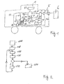
- FIG. 1 shows a schematic representation of a vehicle 1 with an internal combustion engine 2, which drives a generator 3. Furthermore, a battery 4 is provided, which is connected to an electrical connection 5. Instead of the battery 4, other types of electrical energy storage such as capacitors may be provided.
- the electrical connection 5 can be designed in the form of a plug to which an external power source 6 can be connected.
- the battery 4 may be connected via electrical lines directly or via a charger 7 to the terminal 5. In the embodiment in which the battery 4 is connected directly to the electrical connection 5, the charger 7 is arranged outside the vehicle 1.
- the battery 4 is connected via a first electrical line 8 and a first switch 9 to the generator 3 in connection. Furthermore, the battery 4 is connected via second electrical lines 10 with electrical consumers 11 of the vehicle 1 in connection.
- the electrical loads 11 are shown in the form of a block, wherein the electrical loads 11 are supplied via an electrical system of the vehicle from the battery 4 with power.
- the block in the FIG. 1 the electrical system of the vehicle is connected to the various electrical loads such as motors, switches, relays, control devices and / or bulbs.
- the generator 3 via a third electrical line 12 and a second switch 13 with the electrical loads 11, in particular with the electrical system of the vehicle 1, connected.
- the battery 4 is connected via a fourth electrical line 14 to a starter motor 15.
- the fourth electrical lead 14 may be connected to a second battery 16, which in turn communicates with the starter motor 15.
- the second battery 16 instead of the second battery 16 and capacitors, such as so-called supercapacitors, may be provided.
- the second battery 16 or the capacitors via a fifth electrical line 17 to the terminal 5 or, in the presence of the charger 7, be connected to the charger 7.
- the generator 3 may be connected via a sixth electrical line 24 and a third switch 25 to the second battery. Depending on the conduction state of the third switch 25, the generator 3 charges the second battery 16 or not.
- the vehicle 1 further has a control unit 18, which is connected via a first control line 19 to the first switch 9, via a second control line 20 to the second switch 13 and via a third control line 26 to the third switch 25.
- the control unit 18 via a sensor line 21 to the battery 4 and a second sensor line 22 connected to the second battery 16. With the aid of the sensor line 21, the control unit 18 detects the state of charge of the battery 4. Via the second sensor line 22, the control unit 18 detects the state of charge of the second battery 16.
- the generator 3 supplies the battery 4 with electricity and charges it.
- the generator 3 supplies the electrical load 11 or the vehicle electrical system of the vehicle with power.
- the starter 15 and the generator 3 may also be designed in the form of a starter generator.
- the starter 15 is used to start the engine 2.
- the generator 3 is driven by the engine 2 and is used to generate electricity.
- control unit 18 is connected to an output 23, via which information about the state of charge of the battery 4 and / or the second battery 16 can be displayed or output acoustically.
- control unit 18 may be connected to a navigation device which gives the control unit information about the route to be traveled to a destination and in particular information about the distance to a destination or to a charging location with an external power source.
- the charging location may be, for example, at home at the driver's residence.
- FIG. 2 shows a schematic sequence for operating the vehicle 1.
- the battery 4 and / or the second battery 16 are charged via the electrical connection 5 by means of an external power source 6.
- the charger 7 may be arranged in the vehicle or outside the vehicle.
- the energy transfer between the vehicle 1 and the external power supply 6 also contact without the help of an inductive energy transfer occur.
- the vehicle is started, ie, the internal combustion engine 2 is set by means of the starter motor 15 in operation, wherein the first, the second and third switches 9, 13, 25 are opened.
- the internal combustion engine 2 is operated, for example, by the control unit 18 or by a further control unit.
- the control unit 18 checks the state of charge of the battery 4 with the aid of the sensor line 21.
- the control unit 18 compares the current state of charge of the battery 4 with a threshold value.
- the threshold value is stored in a memory of the control unit 18. If the comparison at program point 140 reveals that the state of charge of the battery 4 is above the first threshold value, then the first and second switches 9, 13 remain open.
- the electrical consumers of the vehicle ie the electrical system of the vehicle powered by the battery 4 with electricity.
- a start-stop system of the internal combustion engine 2 is powered only by the battery 4 with power. This represents a first operating phase of the vehicle, which is shown in program item 150.
- the generator 3 can be used to power, for example, smaller consumers, in particular electrical actuators of the internal combustion engine 2, for example, injectors.
- a limit can be stored, which can also be adjustable.
- the generator 3 in the first phase of operation can supply no electrical consumers and no battery with electricity.
- the electrical system which includes essential electrical consumers of the vehicle 1, is supplied in the first operating state only by the battery 4 with power.
- the electrical loads 11 are supplied with power that has been charged from the external power source 6 into the battery 4.
- program item 150 the program branches back to program item 120.
- the program sequence 110 to 140 is run through until the state of charge of the battery 4 drops below the threshold value. This is detected in the query 140 by the controller 18, and it is branched to the program point 200.
- program point 200 which represents a second operating phase of the vehicle, the control unit 18 brings the first and the second switches 9, 13 into a closed position, so that the generator 3 both charges the battery 4 and also supplies the electrical consumers 11 with power.
- the control unit 18 may also close only one of the two switches 9, 13 in the second operating phase.
- the controller 18 and the third switch 24 is turned on. Subsequently, a branch is made back to program point 110. Furthermore, for example, in the second operating phase, a start / stop automatic of the separation motor 2 can be switched off.
- the controller 18 may adjust the threshold for the state of charge of the battery 4, over which the first operating phase and under which the second operating phase, depending on other parameters. For example, when determining the threshold value, a current maximum charge of the battery, which depends on the age of the battery, can be taken into account. In addition, the threshold value can be increased or decreased depending on information of a navigation device. For example, the threshold can be lowered when the vehicle is on the way to the next charging station and the distance is below a predetermined limit. Thus, in the knowledge that the next charging is only a certain distance away, a deeper discharge of the battery 4 are taken as given in purchasing.
- the state of charge of the battery can be estimated as a function of a charging voltage and of a charging current.
- the battery 4 when parking the vehicle not only from external energy sources, but also from internal power sources, such. B. from a vehicle-integrated solar roof with solar cells and / or a thermocouple that acts between vehicle interior and exterior space, are loaded.
- the battery 4 can be charged in all operating phases during braking of the vehicle via a corresponding coupling of the generator 3.
Landscapes
- Engineering & Computer Science (AREA)
- Power Engineering (AREA)
- Transportation (AREA)
- Mechanical Engineering (AREA)
- Chemical & Material Sciences (AREA)
- Combustion & Propulsion (AREA)
- Automation & Control Theory (AREA)
- Electric Propulsion And Braking For Vehicles (AREA)
- Charge And Discharge Circuits For Batteries Or The Like (AREA)
- Control Of Vehicle Engines Or Engines For Specific Uses (AREA)
Applications Claiming Priority (1)
| Application Number | Priority Date | Filing Date | Title |
|---|---|---|---|
| DE102011080427A DE102011080427A1 (de) | 2011-08-04 | 2011-08-04 | Elektrisches Versorgungssystem für ein Fahrzeug |
Publications (2)
| Publication Number | Publication Date |
|---|---|
| EP2554424A2 true EP2554424A2 (fr) | 2013-02-06 |
| EP2554424A3 EP2554424A3 (fr) | 2016-10-12 |
Family
ID=47172234
Family Applications (1)
| Application Number | Title | Priority Date | Filing Date |
|---|---|---|---|
| EP12179067.9A Ceased EP2554424A3 (fr) | 2011-08-04 | 2012-08-02 | Système de allimentation électrique pour vehicule |
Country Status (2)
| Country | Link |
|---|---|
| EP (1) | EP2554424A3 (fr) |
| DE (1) | DE102011080427A1 (fr) |
Cited By (2)
| Publication number | Priority date | Publication date | Assignee | Title |
|---|---|---|---|---|
| CN103950417A (zh) * | 2014-05-15 | 2014-07-30 | 天津永明新能源科技有限公司 | 汽车专用风光互补发电装置 |
| CN111497629A (zh) * | 2019-12-12 | 2020-08-07 | 郭林 | 一种电动汽车及供电控制方法 |
Families Citing this family (1)
| Publication number | Priority date | Publication date | Assignee | Title |
|---|---|---|---|---|
| DE102013112678A1 (de) * | 2013-11-18 | 2015-05-21 | Dr. Ing. H.C. F. Porsche Aktiengesellschaft | Verfahren zur Steuerung eines Ladezustandes einer Batterie eines Bordnetzes |
Family Cites Families (19)
| Publication number | Priority date | Publication date | Assignee | Title |
|---|---|---|---|---|
| US4489242A (en) * | 1981-01-22 | 1984-12-18 | Worst Marc T | Stored power system for vehicle accessories |
| JPH0988778A (ja) * | 1995-07-17 | 1997-03-31 | Denso Corp | 始動発電装置 |
| FR2749991B1 (fr) * | 1996-06-14 | 1998-08-07 | Siemens Automotive Sa | Procede et dispositif de commande d'un alternateur de vehicule automobile |
| US6166523A (en) * | 2000-01-11 | 2000-12-26 | Honeywell International Inc. | Smart alternator method and apparatus for optimizing fuel efficiency and monitoring batteries in an automobile |
| DE102004021317A1 (de) * | 2004-04-30 | 2005-11-24 | S-Y Systems Technologies Europe Gmbh | Bordnetz und Schalter für ein Bordnetz |
| JP2005348576A (ja) * | 2004-06-07 | 2005-12-15 | Auto Network Gijutsu Kenkyusho:Kk | バッテリ管理装置及び管理方法 |
| JP2006230132A (ja) * | 2005-02-18 | 2006-08-31 | Honda Motor Co Ltd | 電流供給方法、内燃機関の始動方法、電源装置及び車両 |
| EP1883552B1 (fr) * | 2005-05-05 | 2012-06-20 | AFS Trinity Power Corporation | Vehicule hybride enfichable a stockage d'energie rapide |
| JP2007008349A (ja) * | 2005-06-30 | 2007-01-18 | Yamaha Motor Co Ltd | ハイブリッド車両 |
| DE102005046340B4 (de) * | 2005-09-28 | 2012-04-19 | Audi Ag | Verfahren zum bedarfsgerechten Einstellen eines Betriebszustands von Verbrauchern eines Energiesystems bei einem Fahrzeug mit einem Start-/Stopp-System |
| DE102006002985A1 (de) * | 2006-01-21 | 2007-08-09 | Bayerische Motoren Werke Ag | Energiespeichersystem für ein Kraftfahrzeug |
| US7692412B2 (en) * | 2006-02-20 | 2010-04-06 | Fujitsu Ten Limited | Charging control apparatus, charging control method |
| DE102006036425A1 (de) * | 2006-08-04 | 2008-02-07 | Bayerische Motoren Werke Ag | System zur Spannungsversorgung von elektrischen Verbrauchern eines Kraftfahrzeugs |
| DE102007003005A1 (de) * | 2007-01-20 | 2008-02-28 | Audi Ag | Batteriesystem und Verfahren zum Betreiben eines Batteriesystems für ein Fahrzeug |
| DE102008017685A1 (de) * | 2008-04-08 | 2008-12-11 | Daimler Ag | Verfahren zur Ermittlung und Anzeige eines Batteriezustandes |
| DE102008062203A1 (de) * | 2008-12-13 | 2010-06-17 | Daimler Ag | Elektrisches Bordnetz für ein Fahrzeug und Verfahren zum Betrieb des elektrischen Bordnetzes |
| JP5413042B2 (ja) * | 2009-08-07 | 2014-02-12 | 株式会社デンソー | 蓄電情報出力装置および蓄電情報出力システム |
| DE102009058895A1 (de) * | 2009-12-18 | 2010-08-05 | Daimler Ag | Vorrichtung und Verfahren zur Steuerung und/oder Regelung eines Kraftfahrzeuggenerators |
| DE102010000679A1 (de) * | 2010-01-05 | 2011-07-07 | Robert Bosch GmbH, 70469 | Verfahren zur Erkennung der Startfähigkeit |
-
2011
- 2011-08-04 DE DE102011080427A patent/DE102011080427A1/de not_active Ceased
-
2012
- 2012-08-02 EP EP12179067.9A patent/EP2554424A3/fr not_active Ceased
Non-Patent Citations (1)
| Title |
|---|
| None |
Cited By (2)
| Publication number | Priority date | Publication date | Assignee | Title |
|---|---|---|---|---|
| CN103950417A (zh) * | 2014-05-15 | 2014-07-30 | 天津永明新能源科技有限公司 | 汽车专用风光互补发电装置 |
| CN111497629A (zh) * | 2019-12-12 | 2020-08-07 | 郭林 | 一种电动汽车及供电控制方法 |
Also Published As
| Publication number | Publication date |
|---|---|
| EP2554424A3 (fr) | 2016-10-12 |
| DE102011080427A1 (de) | 2013-02-07 |
Similar Documents
| Publication | Publication Date | Title |
|---|---|---|
| DE102013221634B4 (de) | Verfahren und System zum Aufladen eines Steckdosenelektrofahrzeugs | |
| EP1593188B1 (fr) | Dispositif pour alimenter en energie un systeme electrique bitension d'un vehicule | |
| DE102019102998A1 (de) | Onboard-dc-ladeschaltung unter verwendung von traktionsantriebskomponenten | |
| EP2528766B1 (fr) | Système de batterie pour véhicules micro-hybrides à consommateurs de forte puissance | |
| DE102014112349A1 (de) | Verfahren zum vorhersagen der dauer eines aufladeprozesses | |
| EP2822808B1 (fr) | Réseau de bord pour un véhicule | |
| WO2002087068A1 (fr) | Dispositif pour alimenter en energie le reseau de bord multitension d'un vehicule | |
| DE102007026164A1 (de) | Elektrisches Versorgungssystem für ein Kraftfahrzeug | |
| DE112013007089T5 (de) | Ladungssteuerungseinrichtung unter Verwendung einer fahrzeugseitigen Solarzelle | |
| DE102015108789A1 (de) | Energieversorgungssystem für ein Kraftfahrzeug | |
| EP3616295A1 (fr) | Circuit et procédé de charge pour un système de stockage d'énergie électrique | |
| DE10213105A1 (de) | Antrieb für ein Kraftfahrzeug | |
| DE102014016620A1 (de) | Verfahren zum Betrieb einer Energiespeichereinrichtung in einem Kraftfahrzeug und Kraftfahrzeug | |
| DE102011109709A1 (de) | Verfahren und System zur Spannungsversorgung eines Bordnetzes eines Fahrzeugs | |
| DE102007004279A1 (de) | Mehrspannungsbordnetz für ein Kraftfahrzeug | |
| WO2010081611A1 (fr) | Réseau de bord pour un véhicule et procédé permettant de réaliser des économies d'énergie | |
| DE102014201362A1 (de) | Verfahren zum Betrieb eines Bordnetzes | |
| EP2670974B1 (fr) | Dispositif d'allumage commandé pour un véhicule à moteur | |
| DE102010062362A1 (de) | Schnellladestation | |
| EP2528767B1 (fr) | Système de batterie pour véhicules micro-hybrides à consommateurs de forte puissance | |
| WO2015172924A1 (fr) | Dispositif et procédé pour charger deux accumulateurs d'énergie | |
| EP3079941A1 (fr) | Précharge d'un accumulateur de circuit intermédiaire électrique | |
| DE102021100443A1 (de) | Einheitliches bordeigenes ladegerät und generator für ein fahrzeug | |
| DE102007014383A1 (de) | Mehrspannungsbordnetz für ein Kraftfahrzeug | |
| DE102012007158A1 (de) | Pulswechselrichter mit Stromzwischenkreis zum Fahren und Laden eines batteriebetriebenen Elektrofahrzeugs |
Legal Events
| Date | Code | Title | Description |
|---|---|---|---|
| PUAI | Public reference made under article 153(3) epc to a published international application that has entered the european phase |
Free format text: ORIGINAL CODE: 0009012 |
|
| AK | Designated contracting states |
Kind code of ref document: A2 Designated state(s): AL AT BE BG CH CY CZ DE DK EE ES FI FR GB GR HR HU IE IS IT LI LT LU LV MC MK MT NL NO PL PT RO RS SE SI SK SM TR |
|
| AX | Request for extension of the european patent |
Extension state: BA ME |
|
| PUAL | Search report despatched |
Free format text: ORIGINAL CODE: 0009013 |
|
| AK | Designated contracting states |
Kind code of ref document: A3 Designated state(s): AL AT BE BG CH CY CZ DE DK EE ES FI FR GB GR HR HU IE IS IT LI LT LU LV MC MK MT NL NO PL PT RO RS SE SI SK SM TR |
|
| AX | Request for extension of the european patent |
Extension state: BA ME |
|
| RIC1 | Information provided on ipc code assigned before grant |
Ipc: B60W 10/26 20060101ALI20160906BHEP Ipc: B60L 11/12 20060101ALI20160906BHEP Ipc: B60R 16/03 20060101ALI20160906BHEP Ipc: B60W 10/08 20060101ALI20160906BHEP Ipc: B60W 10/30 20060101ALI20160906BHEP Ipc: H02J 7/00 20060101ALI20160906BHEP Ipc: B60L 1/00 20060101AFI20160906BHEP Ipc: H02J 7/14 20060101ALI20160906BHEP |
|
| STAA | Information on the status of an ep patent application or granted ep patent |
Free format text: STATUS: REQUEST FOR EXAMINATION WAS MADE |
|
| 17P | Request for examination filed |
Effective date: 20170411 |
|
| RBV | Designated contracting states (corrected) |
Designated state(s): AL AT BE BG CH CY CZ DE DK EE ES FI FR GB GR HR HU IE IS IT LI LT LU LV MC MK MT NL NO PL PT RO RS SE SI SK SM TR |
|
| STAA | Information on the status of an ep patent application or granted ep patent |
Free format text: STATUS: EXAMINATION IS IN PROGRESS |
|
| 17Q | First examination report despatched |
Effective date: 20171115 |
|
| STAA | Information on the status of an ep patent application or granted ep patent |
Free format text: STATUS: EXAMINATION IS IN PROGRESS |
|
| STAA | Information on the status of an ep patent application or granted ep patent |
Free format text: STATUS: THE APPLICATION HAS BEEN REFUSED |
|
| 18R | Application refused |
Effective date: 20200924 |