EP1593188B1 - Dispositif pour alimenter en energie un systeme electrique bitension d'un vehicule - Google Patents
Dispositif pour alimenter en energie un systeme electrique bitension d'un vehicule Download PDFInfo
- Publication number
- EP1593188B1 EP1593188B1 EP04701944A EP04701944A EP1593188B1 EP 1593188 B1 EP1593188 B1 EP 1593188B1 EP 04701944 A EP04701944 A EP 04701944A EP 04701944 A EP04701944 A EP 04701944A EP 1593188 B1 EP1593188 B1 EP 1593188B1
- Authority
- EP
- European Patent Office
- Prior art keywords
- safety
- accumulator
- switch
- converter
- safety switch
- Prior art date
- Legal status (The legal status is an assumption and is not a legal conclusion. Google has not performed a legal analysis and makes no representation as to the accuracy of the status listed.)
- Expired - Fee Related
Links
Images
Classifications
-
- H—ELECTRICITY
- H02—GENERATION; CONVERSION OR DISTRIBUTION OF ELECTRIC POWER
- H02J—CIRCUIT ARRANGEMENTS OR SYSTEMS FOR SUPPLYING OR DISTRIBUTING ELECTRIC POWER; SYSTEMS FOR STORING ELECTRIC ENERGY
- H02J7/00—Circuit arrangements for charging or depolarising batteries or for supplying loads from batteries
- H02J7/14—Circuit arrangements for charging or depolarising batteries or for supplying loads from batteries for charging batteries from dynamo-electric generators driven at varying speed, e.g. on vehicle
- H02J7/1423—Circuit arrangements for charging or depolarising batteries or for supplying loads from batteries for charging batteries from dynamo-electric generators driven at varying speed, e.g. on vehicle with multiple batteries
-
- H—ELECTRICITY
- H02—GENERATION; CONVERSION OR DISTRIBUTION OF ELECTRIC POWER
- H02J—CIRCUIT ARRANGEMENTS OR SYSTEMS FOR SUPPLYING OR DISTRIBUTING ELECTRIC POWER; SYSTEMS FOR STORING ELECTRIC ENERGY
- H02J7/00—Circuit arrangements for charging or depolarising batteries or for supplying loads from batteries
- H02J7/34—Parallel operation in networks using both storage and other dc sources, e.g. providing buffering
- H02J7/345—Parallel operation in networks using both storage and other dc sources, e.g. providing buffering using capacitors as storage or buffering devices
-
- H—ELECTRICITY
- H02—GENERATION; CONVERSION OR DISTRIBUTION OF ELECTRIC POWER
- H02J—CIRCUIT ARRANGEMENTS OR SYSTEMS FOR SUPPLYING OR DISTRIBUTING ELECTRIC POWER; SYSTEMS FOR STORING ELECTRIC ENERGY
- H02J1/00—Circuit arrangements for dc mains or dc distribution networks
- H02J1/08—Three-wire systems; Systems having more than three wires
- H02J1/082—Plural DC voltage, e.g. DC supply voltage with at least two different DC voltage levels
-
- H—ELECTRICITY
- H02—GENERATION; CONVERSION OR DISTRIBUTION OF ELECTRIC POWER
- H02J—CIRCUIT ARRANGEMENTS OR SYSTEMS FOR SUPPLYING OR DISTRIBUTING ELECTRIC POWER; SYSTEMS FOR STORING ELECTRIC ENERGY
- H02J9/00—Circuit arrangements for emergency or stand-by power supply, e.g. for emergency lighting
- H02J9/04—Circuit arrangements for emergency or stand-by power supply, e.g. for emergency lighting in which the distribution system is disconnected from the normal source and connected to a standby source
- H02J9/06—Circuit arrangements for emergency or stand-by power supply, e.g. for emergency lighting in which the distribution system is disconnected from the normal source and connected to a standby source with automatic change-over, e.g. UPS systems
-
- Y—GENERAL TAGGING OF NEW TECHNOLOGICAL DEVELOPMENTS; GENERAL TAGGING OF CROSS-SECTIONAL TECHNOLOGIES SPANNING OVER SEVERAL SECTIONS OF THE IPC; TECHNICAL SUBJECTS COVERED BY FORMER USPC CROSS-REFERENCE ART COLLECTIONS [XRACs] AND DIGESTS
- Y02—TECHNOLOGIES OR APPLICATIONS FOR MITIGATION OR ADAPTATION AGAINST CLIMATE CHANGE
- Y02T—CLIMATE CHANGE MITIGATION TECHNOLOGIES RELATED TO TRANSPORTATION
- Y02T10/00—Road transport of goods or passengers
- Y02T10/60—Other road transportation technologies with climate change mitigation effect
- Y02T10/70—Energy storage systems for electromobility, e.g. batteries
Definitions
- the invention relates to a device for supplying power to a two-voltage on-board network equipped with safety-relevant components, with a starter generator mechanically coupled to an internal combustion engine, which is followed by a bidirectional AC / DC converter whose DC connection via a first switch with a first accumulator, which is a first vehicle electrical system and its loads supplied with energy, and is connected via a second switch with a double-layer capacitor, and with a bidirectional DC / DC converter with a second accumulator, which a second electrical system and its loads with Energy supplied.
- a starter-generator in a motor vehicle can usually be done on a vehicle electrical system voltage of 14V (more precisely 14.4V, which is the charging voltage of a 12V battery).
- the output power, but also the generator power is technically reasonable limited to a maximum of 3kW, otherwise the electrical system currents would be too high.
- a starter-generator can start the internal combustion engine at a vehicle electrical system voltage of 14V and supply the electrical loads while driving, for other functions of receiving or emitting electrical energy such as boost or recuperation (braking) is a power of more than 3kW required. This power can only be achieved with a higher vehicle electrical system voltage.
- 42V-Bordnetze 42V is the charging voltage of a 36V battery developed, which allow the implementation of large electrical power, for example, about 6kW.
- a starter-generator draws the energy from at least one energy storage.
- the starter-generator In generator mode, the starter-generator is driven by the internal combustion engine and is thus able to recharge the energy store (s). This can be done in normal operation with low power, but also in an operation with increased power, for example in recuperation with a power that can correspond to the maximum output of the starter-generator.
- This energy source can be powered by the starter-generator ISG or the accumulator B1 with energy.
- this is a somewhat smaller accumulator in comparison to the 36V accumulator B1, which can take over the power supply of the safety-relevant components for a defined period in the event of failure of ISG or B1.
- the energy content and the "health status" of this additional energy source must of course be known!
- accumulators are not constantly charged or recharged, an exact knowledge of their energy reserves is necessary. The detection of the energy supply of a battery is difficult and complex. In addition, accumulators have a strong dependence of the extractable energy on the temperature and can turn out surprisingly and unpredictably entirely.
- Out DE 198 55 245 A1 is a redundant power supply for electrical loads, in particular for safety-related consumers (electrically actuated brakes) known, which has a first accumulator, which is charged directly from a three-phase generator, and charges the vehicle electrical system and a safety-relevant consumer in a first version.
- a second accumulator which is intended exclusively as an "emergency generator" for safety-relevant consumers, is charged by the three-phase generator via a DC / DC converter.
- Each of these two accumulators is in the event of a short circuit or other error by a charge separation module from its power supply and disconnected by a disconnect module and optionally an additional switch from the consumer.
- two charge separation modules, two separation modules and possibly two additional switches are required for each additional safety-relevant consumer.
- the first and the second accumulator are provided exclusively for the power supply of safety-relevant consumers, whereby a third accumulator is required for the energy supply of the vehicle electrical system.
- a power supply device for on-board, safety-related system components of vehicles which has three (or more) independent energy feeds, one per switch to open and close connection line between each power supply and each system component, and logic control units for the switch.
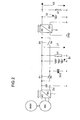
- the invention comprises the technical teaching to simplify the circuit shown in Figure 2 and to replace the required for the energy supply of the safety-relevant components additional energy source by this simple circuit, whereby the existing four energy sources (integrated starter-generator ISG, first accumulator B1, double-layer capacitor DLC and second accumulator B2) can directly take over the power supply of the safety-relevant components depending on availability.
- the security is substantially increased, since instead of a required "emergency generator" in case of failure of the power supply of safety-related components are now three more such additional energy sources alternatively available.
- accumulators as energy storage and double-layer capacitor DLC as a cycle-proof power storage can provide the necessary energy and power for the ISG be made available so that it can use its full capacity in start / stop, boost and recuperated brakes.
- the DLC is another energy source for the safety-related components. All in all, four energy sources are available in a two-voltage vehicle electrical system. This makes it possible to set up a redundant power grid for safety-relevant components.
- the working voltage range of safety-relevant components is very large and can, for example, be between 20V and 58V in a 42V vehicle electrical system.
- FIG. 2 has already been explained above.
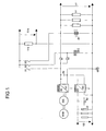
- Figure 1 shows the circuit of an embodiment of a device according to the invention for the power supply of a two-voltage motor vehicle electrical system (for example 14V / 42V) with a starter-generator ISG, a double-layer capacitor DLC and with safety-relevant components V1s, for example an electromechanical brake.
- a two-voltage motor vehicle electrical system for example 14V / 42V
- ISG starter-generator
- DLC double-layer capacitor
- safety-relevant components V1s for example an electromechanical brake.
- integrated starter-generator ISG is connected to a bidirectional AC / DC converter 1 and via this and a first switch S1 with a first accumulator B1 (36V), the larger loads V1 of the first electrical system (42V ) and connected via the AC / DC converter 1 and a second switch S2 to a double-layer capacitor DLC.
- a conventional DC link capacitor Zw is arranged between the DC outputs of the AC / DC converter 1. In that regard, the circuit according to the invention coincides with the circuit known from FIG.
- the AC / DC converter 1 is directly connected to the bidirectional DC / DC converter 2 and via this to the second accumulator B2 (12V), which feeds the smaller loads v2 of the second electrical system (14V).
- the two switches S3 and S4 can be saved.
- Each load is switched on and off for clarity, not shown, with her in-line switch.
- the power supply lines to the respective load groups (consumers) V1, V1s and v2 are provided with arrows, which is intended to indicate that more loads can be connected.
- both the first and the second electrical system with the lead-acid batteries B1 and B2 are significantly relieved.
- the great advantage in addition to the saving of two switches, is for the safety-relevant components of the power supply according to the invention that only three switches X1 to X3 are required for their alternative energy supply from the four existing energy sources ISG, DLC, B1 and B2 and that this simple can be monitored.
- the accumulators are constantly recharged, so you can assume that they are constantly fully charged, and the double-layer capacitor DLC can be controlled very easily. Its energy content can be determined by simple voltage measurement. Also its aging state is, in contrast to an accumulator, simply over a measurement of tension and Determine internal resistance. Lowering its performance by low temperatures are negligible, with some types of capacitors, the performance even increases with decreasing temperatures!
- the upper and lower voltage limits (according to SICAN / VDA recommendation) of 48V or 30V refer only to the voltages in the 42V vehicle electrical system; they are complied with by the device according to the invention.
- the voltage of these two components may temporarily be higher.
- the maximum voltage should be less than 60V, which is the maximum allowable voltage that does not require additional contact protection.
- a higher voltage across the double-layer capacitor DLC has the advantage that the starter-generator ISG can provide a higher torque and the energy storage capacity of the double-layer capacitor DLC, which is quadratic to the voltage, increases. It comes to an increase in performance of the entire electrical system.
- the double-layer capacitor DLC should be operated in a voltage range> 30V ... ⁇ 60V.
- a higher voltage requires an additional contact protection (see above), a deeper discharge than 30V generates very high discharge currents while the load remains constant, whereby only a quarter of the stored energy can be skimmed off, which is to be preserved as a minimal, constant energy reserve.
- An electromechanical brake as a safety-relevant component which can be operated in the entire voltage range of the double-layer capacitor DLC, requires an impaired functionality of the electrical system per braking energy of about 1.4 Wh.
- the energy reserve of 8Wh In an energy supply of the electromechanical brake from a double-layer capacitor with, for example, 115F, the energy reserve of 8Wh has, this energy reserve is sufficient for at least 5 braking operations!
- a total of four energy sources are available in the two-voltage vehicle electrical system (14V / 42V) for the power supply of safety-relevant components: starter-generator ISG, double-layer capacitor DLC, accumulator B1 and accumulator B2.
- Each of these energy sources is able to take over the supply of the safety-relevant components V1s, if the situation requires it. If an energy source fails due to a malfunction / misdiagnosis, further energy sources are available, which can take over the energy supply of the safety-relevant components V1s. Therefore, there is always a multiple redundancy, so that can be omitted exclusively for the safety-relevant components V1s accumulator, a large cost and weight savings.
- the integrated starter-generator ISG is powered by the double-layer capacitor DLC or the first accumulator B1 via switches S1 or S2 and the AC / DC converter 1 (which converts direct current into three-phase current) during motor operation.
- the double-layer capacitor DLC or the accumulator B1 can also be charged by the accumulator B2 or the accumulator B2 by the double-layer capacitor DLC or the accumulator B1.
- the control circuit (not shown) for activating the switches also evaluates the desired and actual state of charge of the energy sources, and monitors the integrated starter-generator ISG and the two transducers 1 and 2.
Landscapes
- Engineering & Computer Science (AREA)
- Power Engineering (AREA)
- Control Of Charge By Means Of Generators (AREA)
- Charge And Discharge Circuits For Batteries Or The Like (AREA)
- Electric Propulsion And Braking For Vehicles (AREA)
- Control Of Eletrric Generators (AREA)
Claims (6)
- Dispositif pour alimenter en énergie un réseau de bord électrique bitension
comprenant un démarreur-générateur (ISG) mécaniquement couplé à un moteur à combustion interne (BKM), et en aval duquel un convertisseur CA-CC bidirectionnel (1) est branché dont les bornes CC- sont connectées via un premier interrupteur (S1) à un premier accumulateur (B1) alimentant en énergie un premier réseau de bord et ses charges (V1), et- sont reliées via un deuxième interrupteur (S2) à un condensateur électrochimique à double couche (DLC) ;caractérisé en ce
comprenant un convertisseur CC-CC bidirectionnel (2) en aval duquel est connecté un deuxième accumulateur (B2) alimentant en énergie un deuxième réseau de bord et ses charges (v2) ; et
comprenant un circuit de commande et de régulation commandant et régulant le déroulement des opérations de ce dispositif - à savoir la détermination du sens de fonctionnement des convertisseurs (1, 2), la charge des sources d'énergie (B1, B2, DLC) et la position de commutation de tous les interrupteurs - ,
que le convertisseur CC-CC bidirectionnel (2) est relié directement aux bornes CC du convertisseur CA-CC bidirectionnel (1),
qu'un premier interrupteur de sécurité (X1) est prévu à travers lequel l'alimentation en énergie de composants relevant de la sécurité (V1s) est effectuée depuis le démarreur-générateur intégré (ISG) via le convertisseur CA-CC bidirectionnel (1) ou, alternativement, depuis le deuxième accumulateur (B2) via le convertisseur CC-CC bidirectionnel (2),
qu'un deuxième interrupteur de sécurité (X2) est prévu à travers lequel l'alimentation en énergie de composants relevant de la sécurité (V1s) est effectuée depuis le condensateur électrochimique à double couche (DLC), et
qu'un troisième interrupteur de sécurité (X3) est prévu à travers lequel l'alimentation en énergie de composants relevant de la sécurité (V1s) est effectuée depuis le premier accumulateur (B1). - Dispositif selon la revendication 1, caractérisé en ce que l'alimentation en énergie de composants relevant de la sécurité (V1s) est effectuée, dans le cas d'un fonctionnement normal, c'est-à-dire dans le mode de fonctionnement en générateur du démarreur-générateur intégré (ISG), depuis le premier accumulateur (B1) via le troisième interrupteur de sécurité (X3).
- Dispositif selon la revendication 1, caractérisé en ce que, lors d'un court-circuit du premier accumulateur (B1), le premier interrupteur (S1) et le troisième interrupteur de sécurité (X3) sont pilotés pour devenir non conducteurs, et que l'alimentation en énergie de composants relevant de la sécurité (V1s) est effectuéea) depuis le démarreur-générateur intégré (ISG) via le convertisseur CA-CC (1) et le premier interrupteur de sécurité (X1), oub) depuis le deuxième accumulateur (B2) via le convertisseur CC-CC (2) et le premier interrupteur de sécurité (X1), ouc) depuis le condensateur électrochimique à double couche (DLC) via le deuxième interrupteur de sécurité (X2).
- Dispositif selon la revendication 1, caractérisé en ce que, lors d'un court-circuit du condensateur électrochimique à double couche (DLC), le deuxième interrupteur (S2) et le deuxième interrupteur de sécurité (X2) sont pilotés en non conducteurs, et que l'alimentation en énergie de composants relevant de la sécurité (V1s) est effectuéea) depuis le premier accumulateur (B1) via le troisième interrupteur de sécurité (X3), oub) depuis le démarreur-générateur intégré (ISG) via le convertisseur CA-CC (1) et le premier interrupteur de sécurité (X1), ouc) depuis le deuxième accumulateur (B2) via le convertisseur CC-CC (2) et le premier interrupteur de sécurité (X1) .
- Dispositif selon la revendication 1, caractérisé en ce que, lors d'un court-circuit à la sortie du courant continu du convertisseur CA-CC (1), le premier interrupteur (S1), le deuxième interrupteur (S2) et le premier interrupteur de sécurité (X1) sont pilotés en non conducteurs, et que l'alimentation en énergie de composants relevant de la sécurité (V1s) est effectuéea) depuis le premier accumulateur (B1) via le troisième interrupteur de sécurité (X3), oub) depuis le condensateur électrochimique à double couche (DLC) via le deuxième interrupteur de sécurité (X2).
- Dispositif selon la revendication 1, caractérisé en ce que, lors d'un court-circuit du deuxième accumulateur d'énergie (B2), l'alimentation en énergie de composants relevant de la sécurité (V1s) est effectuéea) depuis le premier accumulateur (B1) via le troisième interrupteur de sécurité (X3), oub) depuis le condensateur électrochimique à double couche (DLC) via le deuxième interrupteur de sécurité (X2), ouc) depuis le démarreur-générateur intégré (ISG) via le convertisseur CA-CC (1) et le premier interrupteur de sécurité (X1).
Applications Claiming Priority (3)
| Application Number | Priority Date | Filing Date | Title |
|---|---|---|---|
| DE10305357 | 2003-02-10 | ||
| DE10305357A DE10305357B4 (de) | 2003-02-10 | 2003-02-10 | Vorrichtung zur Energieversorgung eines mit sicherheitsrelevanten Komponenten ausgestatteten Zweispannungs-Bordnetzes |
| PCT/EP2004/000217 WO2004070911A1 (fr) | 2003-02-10 | 2004-01-14 | Dispositif pour alimenter en energie un systeme electrique bitension d'un vehicule |
Publications (2)
| Publication Number | Publication Date |
|---|---|
| EP1593188A1 EP1593188A1 (fr) | 2005-11-09 |
| EP1593188B1 true EP1593188B1 (fr) | 2007-07-25 |
Family
ID=32747670
Family Applications (1)
| Application Number | Title | Priority Date | Filing Date |
|---|---|---|---|
| EP04701944A Expired - Fee Related EP1593188B1 (fr) | 2003-02-10 | 2004-01-14 | Dispositif pour alimenter en energie un systeme electrique bitension d'un vehicule |
Country Status (4)
| Country | Link |
|---|---|
| US (1) | US7436080B2 (fr) |
| EP (1) | EP1593188B1 (fr) |
| DE (2) | DE10305357B4 (fr) |
| WO (1) | WO2004070911A1 (fr) |
Families Citing this family (50)
| Publication number | Priority date | Publication date | Assignee | Title |
|---|---|---|---|---|
| DE102004023505B4 (de) | 2004-05-10 | 2022-01-27 | Volkswagen Ag | Verfahren zum Energiemanagement in einem elektrischen System eines Hybridfahrzeuges und ein elektrisches System |
| US20060061210A1 (en) * | 2004-09-17 | 2006-03-23 | Mihai Ralea | Electromechanical braking system with electrical energy back-up |
| US20060108867A1 (en) * | 2004-09-17 | 2006-05-25 | Mihai Ralea | Electromechanical braking system with electrical energy back-up and regenerative energy management |
| DE102005031085A1 (de) * | 2005-07-04 | 2007-01-18 | Robert Bosch Gmbh | Steuergerät für den Personenschutz |
| DE102005060129A1 (de) * | 2005-12-16 | 2007-06-21 | Bayerische Motoren Werke Ag | Verfahren zum Steuern eines Bordnetzes für ein Kraftfahrzeug |
| DE102006010713B4 (de) * | 2006-03-08 | 2010-04-01 | Audi Ag | Bordnetz für ein Fahrzeug und Verfahren zur Energieversorgung eines sicherheitsrelevanten Verbrauchers eines Bordnetzes |
| DE102006014401A1 (de) * | 2006-03-29 | 2007-10-11 | Audi Ag | Bordnetz für ein Fahrzeug und Verfahren zur Steuerung und/oder Regelung einer Leistungsaufnahme von zumindest einer elektrischen Maschine eines Fahrzeugs |
| US7880331B2 (en) * | 2006-12-29 | 2011-02-01 | Cummins Power Generation Ip, Inc. | Management of an electric power generation and storage system |
| ES2573470T3 (es) * | 2006-11-30 | 2016-06-08 | Bayerische Motoren Werke Aktiengesellschaft | Procedimiento y red de a bordo de un vehículo automóvil con aumento temporal previsor del número de revoluciones de marcha al ralentí del motor de combustión |
| US7806095B2 (en) * | 2007-08-31 | 2010-10-05 | Vanner, Inc. | Vehicle starting assist system |
| DE102007043578A1 (de) * | 2007-09-13 | 2009-03-26 | Fachhochschule Bochum | Verfahren und Vorrichtung zur Rückgewinnung von kinetischer Energie eines bewegten Fahrzeuges zur Versorgung sicherheitsrelevanter Fahrzeugfunktionen |
| DE102007048342B4 (de) * | 2007-10-09 | 2012-02-23 | Continental Automotive Gmbh | Bordnetz für ein Kraftfahrzeug |
| DE102008012896A1 (de) * | 2008-03-06 | 2009-09-10 | Robert Bosch Gmbh | Steuergerät und Verfahren zur Ansteuerung von Personenschutzmitteln für ein Fahrzeug |
| DE102008001145A1 (de) * | 2008-04-14 | 2009-10-15 | Robert Bosch Gmbh | Notenergieversorgungsvorrichtung für ein Hybridfahrzeug |
| EP2113409A1 (fr) * | 2008-04-30 | 2009-11-04 | Iveco France S.A. | Système de stockage d'énergie électrique et véhicule à moteur correspondant |
| WO2011121053A1 (fr) * | 2010-03-30 | 2011-10-06 | Continental Automotive Gmbh | Réseau de bord pour véhicule et dispositif de commande pour réguler un flux de courant dans un réseau de bord de véhicule |
| DE102010063598A1 (de) | 2010-12-20 | 2012-06-21 | Continental Automotive Gmbh | Bordnetz für ein Fahrzeug sowie Vorrichtung zur Steuerung eines Stromflusses in einem Bordnetz eines Fahrzeugs |
| DE102010029788B4 (de) * | 2010-06-08 | 2023-05-25 | Bayerische Motoren Werke Aktiengesellschaft | Bordnetz und Verfahren und Vorrichtung zum Betreiben des Bordnetzes |
| DE102010050125A1 (de) * | 2010-11-03 | 2012-05-03 | Audi Ag | Kraftfahrzeug mit einem durch eine erste Batterie gespeisten Niedrigspannungsnetz |
| KR101628399B1 (ko) | 2010-12-01 | 2016-06-09 | 현대자동차주식회사 | 정체구간에서의 차량 isg 제어방법 |
| KR20120060108A (ko) | 2010-12-01 | 2012-06-11 | 현대자동차주식회사 | 아이에스지 시스템 및 그의 제어방법 |
| KR101567104B1 (ko) * | 2010-12-01 | 2015-11-09 | 현대자동차주식회사 | 아이에스지 차량의 아이에스지 표시 장치 및 방법 |
| DE102011011799A1 (de) | 2011-02-19 | 2012-08-23 | Volkswagen Aktiengesellschaft | Verfahren zum Schalten von Energiespeicherzellen eines Energiespeichers für ein Fahrzeug sowie entsprechenden Energiespeicher und Fahrzeug |
| WO2012125963A2 (fr) | 2011-03-16 | 2012-09-20 | Johnson Controls Technology Company | Dispositifs et systèmes de source d'énergie comprenant une batterie et un ultracondensateur |
| US8606447B2 (en) * | 2011-05-23 | 2013-12-10 | GM Global Technology Operations LLC | Method and apparatus to operate a powertrain system including an electric machine having a disconnected high-voltage battery |
| DE102012208520A1 (de) * | 2011-06-17 | 2012-12-20 | Robert Bosch Gmbh | Vorrichtung und Verfahren zur Verbindung von Mehrspannungsbordnetzen |
| US9434258B2 (en) | 2011-11-18 | 2016-09-06 | GM Global Technology Operations LLC | Power converter with diagnostic unit power supply output |
| WO2013107497A1 (fr) * | 2012-01-16 | 2013-07-25 | Schneider Electric Buildings Llc | Réglage de la tension de charge d'un condensateur |
| FR2981521A1 (fr) * | 2012-03-19 | 2013-04-19 | Continental Automotive France | Dispositif reversible de charge de batteries de vehicules electriques ou hybrides |
| WO2015143088A1 (fr) * | 2014-03-19 | 2015-09-24 | Motivo Engineering LLC | Système de distribution et de conversion de puissance mobile |
| DE102014006944B4 (de) * | 2014-05-10 | 2018-11-29 | Audi Ag | Verfahren zum Betrieb einer kraftfahrzeugseitigen elektrischen Bordnetzstruktur, elektrische Bordnetzstruktur für ein Kraftfahrzeug und Kraftfahrzeug |
| DE102014219133A1 (de) | 2014-09-23 | 2016-03-24 | Robert Bosch Gmbh | Bordnetz |
| DE102014226391A1 (de) * | 2014-12-18 | 2016-06-23 | Bayerische Motoren Werke Aktiengesellschaft | Mehr-Speicher Bordnetz |
| JP6308225B2 (ja) * | 2016-01-13 | 2018-04-11 | トヨタ自動車株式会社 | 車載電源システム |
| DE102016201520A1 (de) * | 2016-02-02 | 2017-08-03 | Bayerische Motoren Werke Aktiengesellschaft | Speichersystem für ein Fahrzeug |
| JP6455486B2 (ja) | 2016-06-07 | 2019-01-23 | トヨタ自動車株式会社 | 電源システム |
| US10164522B2 (en) | 2016-09-21 | 2018-12-25 | Fca Us Llc | Selective response control of DC-DC converters in mild hybrid electric vehicles |
| JP6757503B2 (ja) * | 2017-08-24 | 2020-09-23 | 株式会社オートネットワーク技術研究所 | 電源システム及び電気自動車 |
| CN108270279A (zh) * | 2018-03-25 | 2018-07-10 | 郑州蓝之夜电子科技有限公司 | 适用于商用车的双电压电源系统及应用该系统的汽车 |
| CN108809078A (zh) * | 2018-08-24 | 2018-11-13 | 北斗航天汽车(北京)有限公司 | 基于北斗导航系统的车载智能终端 |
| EP3623226A1 (fr) * | 2018-09-17 | 2020-03-18 | KNORR-BREMSE Systeme für Nutzfahrzeuge GmbH | Alimentation supplémentaire et procédé permettant de fournir une puissance supplémentaire |
| EP3640074B1 (fr) | 2018-10-16 | 2022-12-21 | Ningbo Geely Automobile Research & Development Co. Ltd. | Système d'alimentation électrique |
| CN110752636B (zh) * | 2019-10-23 | 2021-03-19 | 常熟理工学院 | 一种动力电池回收的快速放电方法、电路及装置 |
| US11639143B2 (en) * | 2019-10-23 | 2023-05-02 | Aptiv Technologies Limited | Vehicle electrical interconnection system |
| USD926826S1 (en) | 2020-03-09 | 2021-08-03 | Zimeno, Inc. | Illuminated tractor hood |
| USD916935S1 (en) | 2020-03-09 | 2021-04-20 | Zimeno, Inc. | Tractor front cargo bed |
| DE102020122508A1 (de) | 2020-08-28 | 2022-03-03 | Knorr-Bremse Systeme für Nutzfahrzeuge GmbH | Energieversorgungsvorrichtung, verfahren zum versorgen zumindest eines elektrischen verbrauchers und fahrzeug |
| DE102021200578A1 (de) | 2021-01-22 | 2022-07-28 | Volkswagen Aktiengesellschaft | Kraftfahrzeugbordnetz |
| USD971274S1 (en) * | 2021-07-05 | 2022-11-29 | Zimeno, Inc. | Illuminated tractor |
| DE102022132229A1 (de) | 2022-12-05 | 2024-06-06 | Zf Cv Systems Global Gmbh | Bremssystem für ein Fahrzeug, insbesondere Nutzfahrzeug |
Family Cites Families (9)
| Publication number | Priority date | Publication date | Assignee | Title |
|---|---|---|---|---|
| DE19855245B4 (de) * | 1997-12-02 | 2010-08-12 | Robert Bosch Gmbh | Redundante Spannungsversorgung für elektrische Verbraucher |
| JP4515573B2 (ja) * | 1999-12-20 | 2010-08-04 | 澤藤電機株式会社 | 振動型圧縮機の駆動装置 |
| DE10020304A1 (de) | 2000-04-17 | 2001-10-25 | Volkswagen Ag | Bordnetzsystem |
| DE10103951B4 (de) * | 2001-01-30 | 2005-01-05 | Siemens Ag | Energieversorgungseinrichtung für bordnetzgestützte, sicherheitsrelevante Systemkomponenten von Fahrzeugen |
| DE50105088D1 (de) | 2001-02-16 | 2005-02-17 | Siemens Ag | Kraftfahrzeug-bordnetz |
| WO2002080334A2 (fr) | 2001-03-31 | 2002-10-10 | Heinz Leiber | Dispositif d'entrainement pour un vehicule automobile |
| US6700808B2 (en) * | 2002-02-08 | 2004-03-02 | Mobility Electronics, Inc. | Dual input AC and DC power supply having a programmable DC output utilizing a secondary buck converter |
| US6903950B2 (en) * | 2001-12-03 | 2005-06-07 | Mobility Electronics, Inc. | Programmable power converter |
| US7057376B2 (en) * | 2004-01-14 | 2006-06-06 | Vanner, Inc. | Power management system for vehicles |
-
2003
- 2003-02-10 DE DE10305357A patent/DE10305357B4/de not_active Expired - Fee Related
-
2004
- 2004-01-14 WO PCT/EP2004/000217 patent/WO2004070911A1/fr active IP Right Grant
- 2004-01-14 US US10/545,011 patent/US7436080B2/en not_active Expired - Fee Related
- 2004-01-14 DE DE502004004435T patent/DE502004004435D1/de not_active Expired - Lifetime
- 2004-01-14 EP EP04701944A patent/EP1593188B1/fr not_active Expired - Fee Related
Also Published As
| Publication number | Publication date |
|---|---|
| DE10305357A1 (de) | 2004-08-26 |
| US7436080B2 (en) | 2008-10-14 |
| WO2004070911A1 (fr) | 2004-08-19 |
| EP1593188A1 (fr) | 2005-11-09 |
| DE502004004435D1 (de) | 2007-09-06 |
| DE10305357B4 (de) | 2005-12-22 |
| US20060145536A1 (en) | 2006-07-06 |
Similar Documents
| Publication | Publication Date | Title |
|---|---|---|
| EP1593188B1 (fr) | Dispositif pour alimenter en energie un systeme electrique bitension d'un vehicule | |
| EP1360090B1 (fr) | Reseau de bord de vehicule automobile | |
| EP2460253B1 (fr) | Circuit pour un réseau de bord | |
| EP2528766B1 (fr) | Système de batterie pour véhicules micro-hybrides à consommateurs de forte puissance | |
| DE102013204894A1 (de) | Kraftfahrzeugbordnetz mit wenigstens zwei Energiespeichern, Verfahren zum Betreiben eines Kraftfahrzeugbordnetzes und Mittel zu dessen Implementierung | |
| DE102007026164A1 (de) | Elektrisches Versorgungssystem für ein Kraftfahrzeug | |
| WO2011054588A2 (fr) | Alimentation basse tension | |
| EP3137344B1 (fr) | Circuit stabilisateur pour réseau embarqué | |
| EP2501588A1 (fr) | Réseau de bord, procédé et dispositif permettant de faire fonctionner le réseau de bord | |
| EP2528767B1 (fr) | Système de batterie pour véhicules micro-hybrides à consommateurs de forte puissance | |
| WO2013160031A1 (fr) | Réseau électrique de bord d'un véhicule automobile comprenant au moins deux sous-réseaux | |
| DE102010017417A1 (de) | Elektrisches Versorgungs- und Startsystem für ein Kraftfahrzeug und Verfahren zum Betrieb des elektrischen Versorgungs- und Startsystems | |
| DE102012203467A1 (de) | Bordnetz für ein Fahrzeug | |
| DE10258894B3 (de) | Energieversorgungseinrichtung für ein Bordnetz von Fahrzeugen | |
| DE10313752B4 (de) | Vorrichtung und Verfahren zum Laden von Batterien eines Mehrspannungsbordnetzes eines Kraftfahrzeuges | |
| WO2004006422A1 (fr) | Reseau de bord de vehicule automobile | |
| EP1918192A2 (fr) | Submersible | |
| DE10317362B4 (de) | Fahrzeugbordnetz und Verfahren zum Betreiben eines Fahrzeugbordnetzes | |
| EP1410482A2 (fr) | Dispositif d'entrainement pour un vehicule automobile | |
| DE10324250B4 (de) | Spannungsversorgungssystem für sicherheitsrelevante elektrische Verbraucher | |
| DE102012209453A1 (de) | Kraftfahrzeugbordnetz mit einer elektrischen Maschine und wenigstens zwei Energiespeichern mit unterschiedlichen Ladespannungen sowie Verfahren zum Betreiben desselben | |
| EP3747687A1 (fr) | Système d'accumulation d'énergie électrique et son procédé de fonctionnement | |
| DE102016211164A1 (de) | Kraftfahrzeugbordnetz mit wenigstens zwei Energiespeichern, Verfahren zum Betreiben eines Kraftfahrzeugbordnetzes und Mittel zu dessen Implementierung | |
| WO2012062599A2 (fr) | Module de stockage d'énergie, système comprenant un tel module et procédé de commande | |
| DE102015210264A1 (de) | Verbessertes Antriebs- und Bordnetzsystem für ein elektrisch angetriebenes Fahrzeug |
Legal Events
| Date | Code | Title | Description |
|---|---|---|---|
| PUAI | Public reference made under article 153(3) epc to a published international application that has entered the european phase |
Free format text: ORIGINAL CODE: 0009012 |
|
| 17P | Request for examination filed |
Effective date: 20050713 |
|
| AK | Designated contracting states |
Kind code of ref document: A1 Designated state(s): AT BE BG CH CY CZ DE DK EE ES FI FR GB GR HU IE IT LI LU MC NL PT RO SE SI SK TR |
|
| AX | Request for extension of the european patent |
Extension state: AL LT LV MK |
|
| DAX | Request for extension of the european patent (deleted) | ||
| RBV | Designated contracting states (corrected) |
Designated state(s): DE FR GB IT |
|
| GRAP | Despatch of communication of intention to grant a patent |
Free format text: ORIGINAL CODE: EPIDOSNIGR1 |
|
| GRAS | Grant fee paid |
Free format text: ORIGINAL CODE: EPIDOSNIGR3 |
|
| GRAA | (expected) grant |
Free format text: ORIGINAL CODE: 0009210 |
|
| AK | Designated contracting states |
Kind code of ref document: B1 Designated state(s): DE FR GB IT |
|
| REG | Reference to a national code |
Ref country code: GB Ref legal event code: FG4D Free format text: NOT ENGLISH |
|
| GBT | Gb: translation of ep patent filed (gb section 77(6)(a)/1977) |
Effective date: 20070807 |
|
| REF | Corresponds to: |
Ref document number: 502004004435 Country of ref document: DE Date of ref document: 20070906 Kind code of ref document: P |
|
| ET | Fr: translation filed | ||
| PLBE | No opposition filed within time limit |
Free format text: ORIGINAL CODE: 0009261 |
|
| STAA | Information on the status of an ep patent application or granted ep patent |
Free format text: STATUS: NO OPPOSITION FILED WITHIN TIME LIMIT |
|
| 26N | No opposition filed |
Effective date: 20080428 |
|
| REG | Reference to a national code |
Ref country code: FR Ref legal event code: TP |
|
| REG | Reference to a national code |
Ref country code: GB Ref legal event code: 732E Free format text: REGISTERED BETWEEN 20110825 AND 20110831 |
|
| REG | Reference to a national code |
Ref country code: FR Ref legal event code: PLFP Year of fee payment: 13 |
|
| REG | Reference to a national code |
Ref country code: FR Ref legal event code: PLFP Year of fee payment: 14 |
|
| REG | Reference to a national code |
Ref country code: FR Ref legal event code: PLFP Year of fee payment: 15 |
|
| PGFP | Annual fee paid to national office [announced via postgrant information from national office to epo] |
Ref country code: DE Payment date: 20180131 Year of fee payment: 15 |
|
| PGFP | Annual fee paid to national office [announced via postgrant information from national office to epo] |
Ref country code: IT Payment date: 20190124 Year of fee payment: 16 Ref country code: FR Payment date: 20190123 Year of fee payment: 16 Ref country code: GB Payment date: 20190121 Year of fee payment: 16 |
|
| REG | Reference to a national code |
Ref country code: DE Ref legal event code: R119 Ref document number: 502004004435 Country of ref document: DE |
|
| PG25 | Lapsed in a contracting state [announced via postgrant information from national office to epo] |
Ref country code: DE Free format text: LAPSE BECAUSE OF NON-PAYMENT OF DUE FEES Effective date: 20190801 |
|
| REG | Reference to a national code |
Ref country code: DE Ref legal event code: R081 Ref document number: 502004004435 Country of ref document: DE Owner name: VITESCO TECHNOLOGIES GMBH, DE Free format text: FORMER OWNER: CONTINENTAL AUTOMOTIVE GMBH, 30165 HANNOVER, DE |
|
| GBPC | Gb: european patent ceased through non-payment of renewal fee |
Effective date: 20200114 |
|
| PG25 | Lapsed in a contracting state [announced via postgrant information from national office to epo] |
Ref country code: GB Free format text: LAPSE BECAUSE OF NON-PAYMENT OF DUE FEES Effective date: 20200114 Ref country code: FR Free format text: LAPSE BECAUSE OF NON-PAYMENT OF DUE FEES Effective date: 20200131 |
|
| PG25 | Lapsed in a contracting state [announced via postgrant information from national office to epo] |
Ref country code: IT Free format text: LAPSE BECAUSE OF NON-PAYMENT OF DUE FEES Effective date: 20200114 |