EP2554211A1 - Instrument pour insérer un suppositoire - Google Patents
Instrument pour insérer un suppositoire Download PDFInfo
- Publication number
- EP2554211A1 EP2554211A1 EP11382273A EP11382273A EP2554211A1 EP 2554211 A1 EP2554211 A1 EP 2554211A1 EP 11382273 A EP11382273 A EP 11382273A EP 11382273 A EP11382273 A EP 11382273A EP 2554211 A1 EP2554211 A1 EP 2554211A1
- Authority
- EP
- European Patent Office
- Prior art keywords
- tube
- suppository
- instrument
- plunger
- securement means
- Prior art date
- Legal status (The legal status is an assumption and is not a legal conclusion. Google has not performed a legal analysis and makes no representation as to the accuracy of the status listed.)
- Withdrawn
Links
Images


Classifications
-
- A—HUMAN NECESSITIES
- A61—MEDICAL OR VETERINARY SCIENCE; HYGIENE
- A61M—DEVICES FOR INTRODUCING MEDIA INTO, OR ONTO, THE BODY; DEVICES FOR TRANSDUCING BODY MEDIA OR FOR TAKING MEDIA FROM THE BODY; DEVICES FOR PRODUCING OR ENDING SLEEP OR STUPOR
- A61M31/00—Devices for introducing or retaining media, e.g. remedies, in cavities of the body
- A61M31/007—Injectors for solid bodies, e.g. suppositories
-
- A—HUMAN NECESSITIES
- A61—MEDICAL OR VETERINARY SCIENCE; HYGIENE
- A61F—FILTERS IMPLANTABLE INTO BLOOD VESSELS; PROSTHESES; DEVICES PROVIDING PATENCY TO, OR PREVENTING COLLAPSING OF, TUBULAR STRUCTURES OF THE BODY, e.g. STENTS; ORTHOPAEDIC, NURSING OR CONTRACEPTIVE DEVICES; FOMENTATION; TREATMENT OR PROTECTION OF EYES OR EARS; BANDAGES, DRESSINGS OR ABSORBENT PADS; FIRST-AID KITS
- A61F13/00—Bandages or dressings; Absorbent pads
- A61F13/15—Absorbent pads, e.g. sanitary towels, swabs or tampons for external or internal application to the body; Supporting or fastening means therefor; Tampon applicators
- A61F13/20—Tampons, e.g. catamenial tampons; Accessories therefor
- A61F13/26—Means for inserting tampons, i.e. applicators
- A61F13/266—Insertion devices, e.g. rods or plungers, separate from the tampon
-
- A—HUMAN NECESSITIES
- A61—MEDICAL OR VETERINARY SCIENCE; HYGIENE
- A61M—DEVICES FOR INTRODUCING MEDIA INTO, OR ONTO, THE BODY; DEVICES FOR TRANSDUCING BODY MEDIA OR FOR TAKING MEDIA FROM THE BODY; DEVICES FOR PRODUCING OR ENDING SLEEP OR STUPOR
- A61M5/00—Devices for bringing media into the body in a subcutaneous, intra-vascular or intramuscular way; Accessories therefor, e.g. filling or cleaning devices, arm-rests
- A61M5/50—Devices for bringing media into the body in a subcutaneous, intra-vascular or intramuscular way; Accessories therefor, e.g. filling or cleaning devices, arm-rests having means for preventing re-use, or for indicating if defective, used, tampered with or unsterile
- A61M5/5013—Means for blocking the piston or the fluid passageway to prevent illegal refilling of a syringe
- A61M5/502—Means for blocking the piston or the fluid passageway to prevent illegal refilling of a syringe for blocking the piston
-
- F—MECHANICAL ENGINEERING; LIGHTING; HEATING; WEAPONS; BLASTING
- F04—POSITIVE - DISPLACEMENT MACHINES FOR LIQUIDS; PUMPS FOR LIQUIDS OR ELASTIC FLUIDS
- F04C—ROTARY-PISTON, OR OSCILLATING-PISTON, POSITIVE-DISPLACEMENT MACHINES FOR LIQUIDS; ROTARY-PISTON, OR OSCILLATING-PISTON, POSITIVE-DISPLACEMENT PUMPS
- F04C2270/00—Control; Monitoring or safety arrangements
- F04C2270/04—Force
- F04C2270/042—Force radial
- F04C2270/0421—Controlled or regulated
Definitions
- the present invention relates to an instrument for inserting a suppository.
- US Patent No. 5860946 the disclosure of which is incorporated herein by reference, describes an instrument for inserting a suppository, comprising a tube with a first end which is adapted for receiving a suppository and a second end through which a plunger is inserted in the tube.
- the first end defines the front or distal end of the instrument in the direction of insertion, and the second end defines the rear or proximal end.
- the plunger has corresponding first and second ends, the first end having a circular cross section and two axially spaced circumferential flanges and the second end adapted to project from the second end of the tube before manual actuation of the instrument by the user to eject the suppository from the first end of the tube.
- the first end of the tube has an inwardly extending shoulder which engages between said flanges of the plunger, this engagement having the purpose of holding the plunger in the tube, with the second end projecting form the tube as described above, before the suppository is ejected.
- the first end of the plunger is divided in to a number of sectors by radial slots.
- the suppository Prior to ejection, the suppository is held in the first end of the tube of the prior art device by opposite resilient tongues having, in walls facing each other, recesses mating the outer contour of the suppository.
- the user manually actuates the instrument by pushing the projecting second end of the plunger fully into the tube, which causes the plunger to disengage from its position held by the shoulder and the flanges and move forwards in the tube to push the suppository out of the front end of the tube.
- the prior art device has a number of disadvantages.
- the suppository can become damaged by scraping against the tongue walls of the tube in the ejection process.
- Another disadvantage is that the user has no way to know with relative certainty that the suppository has been ejected correctly - for example in the vicinity of the cervix as far as an intravaginal applicator is concerned.
- the holding cooperation between the shoulder and the flanges, which provides the pre-actuation holding of the plunger, is weak and the plunger can quite easily be prematurely pushed forwards in the tube to eject the suppository. After actuation the plunger can freely move forwards and backwards in the tube and can even be returned to the held condition.
- the present invention aims to at least partially overcome these problems or at least to provide an alternative instrument for inserting a suppository.
- the present invention provides an instrument for inserting a suppository, comprising:
- the instrument may be provided with securement means to (a) secure the plunger in the tube at a first position, prior to actuation of the instrument, in which the suppository is retained in the space defined in the first end of the tube, while allowing a user to manually release the securement means to move the plunger to actuate the instrument, and to (b) secure the plunger in the tube at a second position which is only achievable after the plunger has been moved to eject the suppository from the forward end of the instrument.
- the contacting cooperation between at least one part of the plunger and at least one part of the tube may, for example, be obtained by direct contacting cooperation between a cooperating shoulder of the front end of the plunger and an internal tapering face of the at least one member.
- the arrangement may, for example, be such that in use the suppository does not contact the at least one member to cause movement thereof.
- the at least one member may, for example, comprise a pair of opposed, resiliently mutually outwardly flexible, forwardly directed tongues of the wall of the tube at the first end thereof.
- the tongues may be provided with mutually inwardly directed lips.
- the parts may, for example, be arranged so that the movement between the first and the second condition of the member(s) starts immediately before the suppository is pushed from behind.
- This instrument effectively solves the problem of possible damage to the suppository by scraping against the internal walls of the front end of the tube, as found in the prior art.
- the movement of the at least one member to allow the suppository to exit the tube takes place via contacting cooperation between at least one part of the plunger and at least one part of the tube, that is, without the need for the suppository itself to play a part in moving the member(s) to allow the suppository to exit the tube.
- the moving parts by preferably arranging the moving parts so that the movement between the first and the second condition of the member(s) starts immediately before the suppository is pushed from behind, the suppository cannot fall out of the tube too early.
- the suppository may mildly touch the at least one moveable member, or may encounter other mild resistance from the at least one moveable member, when ejected past it, provided always that the second condition of the moveable member(s) offers substantially less resistance to ejection than the first condition, and that the movement between the first and the second condition of the member(s) takes place via contacting cooperation between at least one part of the plunger and at least one part of the tube.
- the present invention provides an instrument for inserting a suppository, which instrument comprises:
- This instrument effectively solves the problem of the user not being certain that the instrument has been correctly actuated, as found in the prior art.
- the plunger of the actuated instrument is secured in a position which is only achievable after the plunger has been moved to eject the suppository from the forward end of the instrument.
- the securement means so that the act of manual release requires a specific manual action such as pushing the plunger into the tube, and/or application of finger or thumb pressure on a part of the instrument, and/or by arranging for that act of manual release to be accompanied by a characteristic signal such as a click or other sound, the user has complete certainty during use of the instrument as to what is happening at the front end.
- the securement of the plunger in the tube at the second position may be manually released to allow the plunger to be drawn back out of the tube to reset the instrument.
- the first and second aspects of the invention may conveniently be used together, although they do not have to be.
- the tube and plunger may be formed in any suitable material, such as moulded plastics.
- suitable moulding methods include, for example, blow molding, compression molding, extrusion molding and injection molding.
- the tube may have any internal transverse cross-sectional shape, for example circular, oval, polygonal, rectangular.
- the plunger may suitably has a corresponding external transverse cross-sectional shape, to be snugly retained in the tube and slidable therein.
- the tube which has an internal shape that limits the freedom of rotational movement of a correspondingly shaped plunger in the tube.
- the tube may have a rectangular internal transverse cross-sectional shape, having two long sides and two short sides.
- a corresponding plunger can be disposed in the tube in only two orientations with no rotational freedom.
- the member(s) provided at the first end of the tube can be one or more tongue, for example forwardly projecting and forming part of the wall defining the space for receiving the suppository, most suitably a pair of such tongues at opposite sides of the space to overlie the small dimension of a typical round tablet-shaped suppository.
- the one or more tongue can suitably be resiliently outwardly flexible in response to movement of the plunger in the tube, such that in the outwardly flexed condition the suppository can exit the tube when pushed by the plunger from behind.
- the one or more tongue can suitably be provided with an internally directed lip to assist retention of the suppository behind the lip in the space defined at the first end of the tube, before ejection, provided that in the second condition of the one or more tongue the suppository is substantially free to exit the instrument.
- the tube member(s) may be moved by any suitable means.
- Cooperating formation(s) on internal face(s) of the member(s) and on the exterior of the plunger may, for example, serve to move the member(s) outwardly in response to forward movement of the plunger in the tube.
- Suitable formations include cooperating angled or tapered shoulders and projections on the parts, as will be readily understood by the reader.
- the use of cross-sectional configurations of the tube and plunger that restrain rotational movement of the plunger in the tube has the advantage that manually operable parts of the securement means can be provided on the external surface of the tube, for example at or towards the second end of the tube, and any cooperating parts on the plunger can be easily aligned with the external parts of the tube simply on inserting the plunger into the tube, all possible rotational orientations for the plunger within the tube being workable in this respect.
- the securement means may comprise parts provided externally of the tube on opposite sides of the tube. Such parts may suitably be operable by pushing the plunger into the tube, where this action is not prevented by any stop or the like, and/or a squeezing action between thumb and fingers of the user.
- the manual release of the securement means in the first position may be by pushing the plunger into the tube.
- the manual release of the securement means in the second position to reset the instrument may be by a squeezing action between thumb and fingers of the user.
- the manually operable parts may include finger grip depressions, sprung projections such as buttons or levers, and others as are conventional in manually operable release mechanisms, including any combination thereof.
- the manner of use of the instrument is largely similar to the use of the prior art instrument mentioned above. Briefly, the suppository is manually located in the space at the first (forward) end of the tube, taking care not to damage the suppository. The plunger is then loaded into the tube from the second (rearward) end.
- pushing of the plunger forwards will splay the tongue(s) or other moveable member(s) at the front end of the tube, allowing release of the suppository after the instrument has been located correctly for administration.
- the securement means With the instrument according to the second aspect of the present invention, at the correct first position the securement means will secure the plunger in the tube and the instrument is ready for use.
- the user pushes the plunger, which action releases the securement means and allows the plunger to go fully into the tube.
- the securement means secures the plunger in the second position, typically the position which has been achieved by the plunger at the point of full insertion of the plunger into the tube.
- the user now knows that the suppository has been ejected and can withdraw the instrument.
- the securement means can be released by manual action, to allow the plunger to be withdrawn from the tube.
- an instrument for inserting a suppository for example an intravaginal suppository in round tablet form.
- the illustrated embodiment embodies both aspects of the present invention.
- the instrument comprises a tube 1, having a first end 2 adapted to receive the suppository 3 and defining a forward end of the instrument in use, and a second end 4 defining a rearward end of the instrument in use, and a plunger 5 disposed in the tube 1 and moveable therein to eject the suppository 3 from the forward end of the instrument by causing an action of pushing the suppository from behind.
- the tube 1 and the plunger 5 have a generally rectangular transverse cross-section and the respective cross-sectional dimensions and shapes of the tube 1 and plunger 5 are complementary so that the plunger 5 fits snugly and slidably in the tube 1 with no rotation.
- the first end 2 of the tube 1 has an internal configuration which defines a generally rectangular space 6 for receiving the suppository 3.
- a pair of resiliently outwardly flexible members in the form of forwardly directed tongues 7, 7' is provided at the first end 2 of the tube 1 and disposed to opposite sides of the rectangular space 6 to define the short sides of that rectangular space 6.
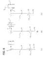
- the pair of opposed tongues 7, 7' is resiliently moveable between a first condition (shown in Figures 3, 4 and 6(a) ) in which the suppository 3 is prevented from exiting the tube and a second condition (shown in Figure 6(c) ) in which the suppository 3 is substantially not prevented from exiting the tube.
- a direct contacting cooperation is established between a cooperating shoulder 8 of each short side of the front end of the rectangular plunger 5 and an internal tapering face 9 of the relevant one of the pair of opposed tongues 7, 7'.
- the pair of opposed tongues 7, 7' is provided with internally directed lips 10, 10' which assist in preventing the suppository 3 from exiting the tube until the tongues 7, 7' have been splayed to a suitable extent.
- Securement means are provided to secure the plunger 5 in the tube 1 at a first position, prior to actuation of the instrument, in which the suppository 3 is retained in the space 6 defined in the first end 2 of the tube 1, while allowing a user to manually release the securement means by pushing the plunger 5 to actuate the instrument.
- the securement means in the illustrated embodiment comprise a pair of mutually outwardly splayed, rearwardly directed, and mutually inwardly resiliently deformable, arms 12, provided on the shaft of the plunger 5, and each arm having at its free rearward end outwardly directed formations 13 which provide in each case a surface that tapers inwards in the forward direction only, but in the rearward direction has a shoulder after the tapering surface.
- Formations 13 are arranged to snap into a first pair of corresponding apertures 14 provided in the wall of the tube 1, to cause the plunger 5 to be releasably retained at the desired first position prior to actuation of the instrument, as shown in Figure 6(a) .
- the plunger 5 is pushed fully into the tube, in the direction of the arrow A in Figure 6(b) .
- the tapering surfaces of the formations 13 slide over the rims of the apertures 14 so that the arms 12 flex inwardly offering no or only little resistance to the pushing of the plunger.
- the pushing of the plunger 5 fully into the tube 1 causes the tongues 7, 7' to splay mutually outwards, in response to the contacting cooperation between the shoulders 8 and the tapering surfaces 9 as described above.
- the front face of the plunger 5 thus can push the suppository 3 from behind, without substantial resistance from the tongues 7, 7', so that the suppository is ejected from the front end of the tube as shown in Figure 6(c) .
- the formations 13 snap into a second pair of corresponding apertures 17 provided in the wall of the tube 1, to cause the plunger to be retained at this second, actuated, position, as shown in Figure 6(c) .
- the securement of the plunger at the fully inserted position in the tube 1 is thus indicative to the user that the suppository has been ejected.
- the fact that the plunger was consciously moved from the first position of releasable retention to the second position of full actuation, with corresponding snap sounds from the arms 12 and formations 13 engaging into the apertures 17, provides certainty that the instrument was properly actuated.
- the user may squeeze the arms 12 together and retract the plunger 5 from the tube 1.
Priority Applications (7)
| Application Number | Priority Date | Filing Date | Title |
|---|---|---|---|
| EP11382273A EP2554211A1 (fr) | 2011-08-05 | 2011-08-05 | Instrument pour insérer un suppositoire |
| ARP120102773A AR087384A1 (es) | 2011-08-05 | 2012-07-30 | Instrumento para insertar un supositorio |
| UY0001034235A UY34235A (es) | 2011-08-05 | 2012-08-01 | Instrumento para insertar un supositorio |
| US14/237,031 US9522259B2 (en) | 2011-08-05 | 2012-08-03 | Instrument for inserting a suppository |
| PCT/EP2012/065270 WO2013020922A1 (fr) | 2011-08-05 | 2012-08-03 | Instrument pour introduire un suppositoire |
| CA2843351A CA2843351A1 (fr) | 2011-08-05 | 2012-08-03 | Instrument pour introduire un suppositoire |
| EP12745482.5A EP2739340A1 (fr) | 2011-08-05 | 2012-08-03 | Instrument pour introduire un suppositoire |
Applications Claiming Priority (1)
| Application Number | Priority Date | Filing Date | Title |
|---|---|---|---|
| EP11382273A EP2554211A1 (fr) | 2011-08-05 | 2011-08-05 | Instrument pour insérer un suppositoire |
Publications (1)
| Publication Number | Publication Date |
|---|---|
| EP2554211A1 true EP2554211A1 (fr) | 2013-02-06 |
Family
ID=46640040
Family Applications (2)
| Application Number | Title | Priority Date | Filing Date |
|---|---|---|---|
| EP11382273A Withdrawn EP2554211A1 (fr) | 2011-08-05 | 2011-08-05 | Instrument pour insérer un suppositoire |
| EP12745482.5A Withdrawn EP2739340A1 (fr) | 2011-08-05 | 2012-08-03 | Instrument pour introduire un suppositoire |
Family Applications After (1)
| Application Number | Title | Priority Date | Filing Date |
|---|---|---|---|
| EP12745482.5A Withdrawn EP2739340A1 (fr) | 2011-08-05 | 2012-08-03 | Instrument pour introduire un suppositoire |
Country Status (6)
| Country | Link |
|---|---|
| US (1) | US9522259B2 (fr) |
| EP (2) | EP2554211A1 (fr) |
| AR (1) | AR087384A1 (fr) |
| CA (1) | CA2843351A1 (fr) |
| UY (1) | UY34235A (fr) |
| WO (1) | WO2013020922A1 (fr) |
Cited By (2)
| Publication number | Priority date | Publication date | Assignee | Title |
|---|---|---|---|---|
| US20190143088A1 (en) * | 2016-05-12 | 2019-05-16 | Cristcot Llc | Single-Use Suppository Insertion Device And Method |
| US11224727B2 (en) | 2012-10-19 | 2022-01-18 | Cristcot Llc | Suppository insertion device, suppository, and method of manufacturing a suppository |
Families Citing this family (1)
| Publication number | Priority date | Publication date | Assignee | Title |
|---|---|---|---|---|
| WO2017075532A1 (fr) * | 2015-10-30 | 2017-05-04 | Acelrx Pharmaceuticals, Inc. | Appareils et procédés de distribution de formes posologiques à administrer par voie transmuqueuse orale |
Citations (6)
| Publication number | Priority date | Publication date | Assignee | Title |
|---|---|---|---|---|
| DE3031408A1 (de) * | 1980-08-20 | 1982-03-25 | Fritz 7015 Korntal-Münchingen Mächtle | Einfuehrinstrument fuer suppositorien |
| FR2610831A1 (fr) * | 1987-02-18 | 1988-08-19 | Hart Louis | Seringue pour introduction d'un suppositoire |
| US5860946A (en) | 1996-07-05 | 1999-01-19 | Novo Nordisk A/S | Instrument for inserting a suppository |
| US20030195459A1 (en) * | 2002-04-15 | 2003-10-16 | Shippert Ronald D. | Applicator for insertion of cargo into a body cavity |
| WO2003101525A1 (fr) * | 2002-05-31 | 2003-12-11 | Reza Hezari | Dispositif pour l'introduction d'un suppositoire |
| US20060217652A1 (en) * | 2005-03-25 | 2006-09-28 | Kimberly-Clark Worldwide, Inc. | Delivery tube assembly for an applicator |
Family Cites Families (13)
| Publication number | Priority date | Publication date | Assignee | Title |
|---|---|---|---|---|
| US3667465A (en) * | 1969-12-08 | 1972-06-06 | Kimberly Clark Co | Applicator tubes for suppositories and the like |
| US3934586A (en) * | 1975-01-22 | 1976-01-27 | Easton Fred H | Non-refillable multiple dosage syringe |
| US4367738A (en) * | 1981-10-28 | 1983-01-11 | Janssen Pharmaceutica Inc. | Pre-filled syringe for abusable drugs |
| US4767413A (en) * | 1987-04-20 | 1988-08-30 | Habley Medical Technology Corporation | Dental syringe having an automatically retractable needle |
| US4826483A (en) * | 1988-05-05 | 1989-05-02 | Paul F. Boyd | Non-reusable syringe |
| US4990136A (en) * | 1989-10-12 | 1991-02-05 | Warner-Lambert Company | Suppository applicator |
| US5263934A (en) * | 1991-11-28 | 1993-11-23 | Haak Abraham Van Den | Stroke limiting syringe with retractable needle |
| EP0634183B1 (fr) * | 1993-07-09 | 2001-12-05 | Terumo Kabushiki Kaisha | Assemblage de seringue |
| FR2757067B1 (fr) * | 1996-12-17 | 1999-07-16 | Sedat | Seringue d'injection a protecteur d'aiguille deplacable |
| GB2385273B (en) * | 2002-02-13 | 2004-05-26 | Deborah Huang | Drug delivery device |
| WO2008085380A1 (fr) * | 2006-12-29 | 2008-07-17 | Tyco Healthcare Group Lp | Procédé permettant de créer une surface d'arrêt sur une tige de piston de seringue |
| US7918821B2 (en) * | 2009-05-05 | 2011-04-05 | Mahurkar Sakharam D | Universal safety syringe |
| CA149342S (en) * | 2012-07-24 | 2014-02-06 | Leon Farma S A Lab | Vaginal applicator |
-
2011
- 2011-08-05 EP EP11382273A patent/EP2554211A1/fr not_active Withdrawn
-
2012
- 2012-07-30 AR ARP120102773A patent/AR087384A1/es unknown
- 2012-08-01 UY UY0001034235A patent/UY34235A/es not_active Application Discontinuation
- 2012-08-03 WO PCT/EP2012/065270 patent/WO2013020922A1/fr active Application Filing
- 2012-08-03 EP EP12745482.5A patent/EP2739340A1/fr not_active Withdrawn
- 2012-08-03 US US14/237,031 patent/US9522259B2/en not_active Expired - Fee Related
- 2012-08-03 CA CA2843351A patent/CA2843351A1/fr not_active Abandoned
Patent Citations (6)
| Publication number | Priority date | Publication date | Assignee | Title |
|---|---|---|---|---|
| DE3031408A1 (de) * | 1980-08-20 | 1982-03-25 | Fritz 7015 Korntal-Münchingen Mächtle | Einfuehrinstrument fuer suppositorien |
| FR2610831A1 (fr) * | 1987-02-18 | 1988-08-19 | Hart Louis | Seringue pour introduction d'un suppositoire |
| US5860946A (en) | 1996-07-05 | 1999-01-19 | Novo Nordisk A/S | Instrument for inserting a suppository |
| US20030195459A1 (en) * | 2002-04-15 | 2003-10-16 | Shippert Ronald D. | Applicator for insertion of cargo into a body cavity |
| WO2003101525A1 (fr) * | 2002-05-31 | 2003-12-11 | Reza Hezari | Dispositif pour l'introduction d'un suppositoire |
| US20060217652A1 (en) * | 2005-03-25 | 2006-09-28 | Kimberly-Clark Worldwide, Inc. | Delivery tube assembly for an applicator |
Cited By (4)
| Publication number | Priority date | Publication date | Assignee | Title |
|---|---|---|---|---|
| US11224727B2 (en) | 2012-10-19 | 2022-01-18 | Cristcot Llc | Suppository insertion device, suppository, and method of manufacturing a suppository |
| US20190143088A1 (en) * | 2016-05-12 | 2019-05-16 | Cristcot Llc | Single-Use Suppository Insertion Device And Method |
| JP2019516462A (ja) * | 2016-05-12 | 2019-06-20 | クリストコット エルエルシー | 使い捨て座薬挿入装置及び方法 |
| US11298515B2 (en) * | 2016-05-12 | 2022-04-12 | Cristcot Llc | Single-use suppository insertion device and method |
Also Published As
| Publication number | Publication date |
|---|---|
| US20140171882A1 (en) | 2014-06-19 |
| UY34235A (es) | 2013-02-28 |
| CA2843351A1 (fr) | 2013-02-14 |
| AR087384A1 (es) | 2014-03-19 |
| WO2013020922A1 (fr) | 2013-02-14 |
| US9522259B2 (en) | 2016-12-20 |
| EP2739340A1 (fr) | 2014-06-11 |
Similar Documents
| Publication | Publication Date | Title |
|---|---|---|
| EP1913872A1 (fr) | Dispositif d'insertion d'aiguille, et ensemble de lancette et ensemble d'injecteur formant celui-ci | |
| JP5786852B2 (ja) | 鼻腔投与容器 | |
| JP4981339B2 (ja) | 内視鏡用注射具 | |
| US4052788A (en) | Tool for removing a snap-in bushing from a mounting panel hole | |
| EP2554211A1 (fr) | Instrument pour insérer un suppositoire | |
| JP4246946B2 (ja) | インプラント・シリンジ | |
| US20090223028A1 (en) | Magazine type clipping device | |
| JP2010035853A (ja) | 連発式クリップ処置具 | |
| AU2004226916B1 (en) | Single-use syringe | |
| JP5726093B2 (ja) | タンポン・アプリケータユニット | |
| US9795207B2 (en) | Case, specifically for containing a stick such as a lipstick, and product including a stick packaged in such a case | |
| CN108136133B (zh) | 注射器型喷出器 | |
| JP6305793B2 (ja) | 定量シリンジ型噴出器 | |
| US10898391B2 (en) | Compact tampon applicator with two-piece plunger | |
| JP2008142565A (ja) | ポジティブな針保持を具えた1回使用引込み式シリンジ | |
| JP5199434B2 (ja) | ダイレーター | |
| TW201306888A (zh) | 插入栓劑之儀器 | |
| JP2009268637A (ja) | ダミークリップ、連結クリップパッケージ、クリップ装填方法 | |
| JP3028696U (ja) | 棒巻き食品用スティック | |
| JP6165655B2 (ja) | 定量シリンジ型噴出器 | |
| EP1629858A1 (fr) | Seringue à usage unique | |
| JP5868674B2 (ja) | 座薬挿入器具 | |
| JP2007267907A (ja) | シリンジ | |
| JP2006296805A (ja) | 引込み式注射針を傾ける装置 | |
| JP6305792B2 (ja) | 定量シリンジ型噴出器 |
Legal Events
| Date | Code | Title | Description |
|---|---|---|---|
| PUAI | Public reference made under article 153(3) epc to a published international application that has entered the european phase |
Free format text: ORIGINAL CODE: 0009012 |
|
| AK | Designated contracting states |
Kind code of ref document: A1 Designated state(s): AL AT BE BG CH CY CZ DE DK EE ES FI FR GB GR HR HU IE IS IT LI LT LU LV MC MK MT NL NO PL PT RO RS SE SI SK SM TR |
|
| AX | Request for extension of the european patent |
Extension state: BA ME |
|
| STAA | Information on the status of an ep patent application or granted ep patent |
Free format text: STATUS: THE APPLICATION IS DEEMED TO BE WITHDRAWN |
|
| 18D | Application deemed to be withdrawn |
Effective date: 20130807 |