EP2553379B1 - Dazzlers - Google Patents
Dazzlers Download PDFInfo
- Publication number
- EP2553379B1 EP2553379B1 EP11712305.9A EP11712305A EP2553379B1 EP 2553379 B1 EP2553379 B1 EP 2553379B1 EP 11712305 A EP11712305 A EP 11712305A EP 2553379 B1 EP2553379 B1 EP 2553379B1
- Authority
- EP
- European Patent Office
- Prior art keywords
- dazzle
- target
- stray
- range
- radiation
- Prior art date
- Legal status (The legal status is an assumption and is not a legal conclusion. Google has not performed a legal analysis and makes no representation as to the accuracy of the status listed.)
- Active
Links
- 230000005855 radiation Effects 0.000 claims description 24
- 238000001514 detection method Methods 0.000 claims description 21
- 238000013459 approach Methods 0.000 claims description 6
- 238000000034 method Methods 0.000 claims description 6
- 230000008569 process Effects 0.000 claims description 6
- 238000012545 processing Methods 0.000 claims description 2
- 230000004044 response Effects 0.000 claims description 2
- 238000010586 diagram Methods 0.000 description 3
- 230000007246 mechanism Effects 0.000 description 3
- 238000004458 analytical method Methods 0.000 description 2
- 230000008859 change Effects 0.000 description 2
- 230000001427 coherent effect Effects 0.000 description 2
- 238000012544 monitoring process Methods 0.000 description 2
- 241001465754 Metazoa Species 0.000 description 1
- 206010057430 Retinal injury Diseases 0.000 description 1
- 230000003044 adaptive effect Effects 0.000 description 1
- 230000002238 attenuated effect Effects 0.000 description 1
- 238000005516 engineering process Methods 0.000 description 1
- 230000002401 inhibitory effect Effects 0.000 description 1
- 238000005259 measurement Methods 0.000 description 1
- 230000004048 modification Effects 0.000 description 1
- 238000012986 modification Methods 0.000 description 1
- 230000009467 reduction Effects 0.000 description 1
- 230000000007 visual effect Effects 0.000 description 1
Images


Classifications
-
- F—MECHANICAL ENGINEERING; LIGHTING; HEATING; WEAPONS; BLASTING
- F41—WEAPONS
- F41H—ARMOUR; ARMOURED TURRETS; ARMOURED OR ARMED VEHICLES; MEANS OF ATTACK OR DEFENCE, e.g. CAMOUFLAGE, IN GENERAL
- F41H13/00—Means of attack or defence not otherwise provided for
- F41H13/0043—Directed energy weapons, i.e. devices that direct a beam of high energy content toward a target for incapacitating or destroying the target
- F41H13/005—Directed energy weapons, i.e. devices that direct a beam of high energy content toward a target for incapacitating or destroying the target the high-energy beam being a laser beam
- F41H13/0056—Directed energy weapons, i.e. devices that direct a beam of high energy content toward a target for incapacitating or destroying the target the high-energy beam being a laser beam for blinding or dazzling, i.e. by overstimulating the opponent's eyes or the enemy's sensor equipment
-
- F—MECHANICAL ENGINEERING; LIGHTING; HEATING; WEAPONS; BLASTING
- F41—WEAPONS
- F41H—ARMOUR; ARMOURED TURRETS; ARMOURED OR ARMED VEHICLES; MEANS OF ATTACK OR DEFENCE, e.g. CAMOUFLAGE, IN GENERAL
- F41H13/00—Means of attack or defence not otherwise provided for
- F41H13/0043—Directed energy weapons, i.e. devices that direct a beam of high energy content toward a target for incapacitating or destroying the target
- F41H13/0087—Directed energy weapons, i.e. devices that direct a beam of high energy content toward a target for incapacitating or destroying the target the high-energy beam being a bright light, e.g. for dazzling or blinding purposes
Definitions
- This invention relates to dazzlers.
- a dazzler is used to emit a beam of high intensity radiation, usually laser, towards a human or animal target temporarily to blind the target or to provide visual distraction or a warning.
- Typical existing dazzle lasers are of fixed power which places a lower limit on the nominal ocular hazard distance (that is the distance at which the laser becomes eye safe) and therefore the range over which the device is of use. This requires user judgment and, in order to have a practical minimum range, limits the laser power and therefore the upper range limit a laser dazzler is known from US 2005/0185403
- this invention provides a dazzle apparatus comprising a radiation source for emitting a dazzle beam of radiation towards a target to be dazzled, the target being at a variable range, a beam control system to control the strength of the dazzle beam in accordance with the range of said target to deliver to said target radiation of sufficient intensity momentarily to dazzle a user, and a stray detector for detecting approach of a secondary object towards said dazzle beam, or vice versa and, in response to such approach, to reduce the strength of or inhibit the beam.
- the dazzle apparatus modulates the strength of the radiation to ensure that the beam is effective to dazzle the target without causing permanent ocular damage, thereby potentially increasing the range over which the dazzler may be effectively used and prevents inadvertent incidence of the dazzle beam on a secondary target which moves towards the dazzle beam or towards which the dazzle beam moves.
- the device may receive target range data from an external device or more preferably from a range finder associated with the dazzler.
- the range finder may conveniently be a laser range finder.
- the range finder may use reflections of the dazzle laser suitably attenuated if required to determine the range of the target, or it could use a separate laser.
- the beam control may adjust the strength of the beam by adjusting the source power, by attenuating the beam using e.g. an acousto-optic modulator, or it may adjust the strength of the beam by adjusting the divergence of the beam so as to adjust the intensity or laser power per unit area.
- the divergence of the beam of radiation may be adjusted by means of an adjustable beam expander.
- the stray detector may include a stray detection beam source for emitting at least one stray detection beam to illuminate an area adjacent said dazzle beam and a stray detection receiver for detecting and processing radiation reflected by said at least one secondary object to determine a position of the secondary object relative to the dazzle beam.
- the stray detector source includes a beam shaper whereby the stray detector beam has a flattened shape in which the beam divergence in one plane is similar to that of the dazzle beam and is significantly greater in a perpendicular plane.
- the beam shaper may be a lens or grating.
- said stray detector source may emit a plurality of stray detector beams each disposed to illuminate a respective area adjacent said dazzle beam. These may be from a single source or a plurality of sources. In another arrangement said stray detector source may be operable to scan one or more stray detector beams across an area adjacent the dazzle beam.
- the stray detector may be operable to track the position of a secondary object and to predict the trajectory thereof, with said beam control system being operable to reduce the strength of, or inhibit, the dazzle beam if the predicted trajectory passes through, or within a preset distance of, the dazzle beam.
- the beam control system may be operable also to control the angular position of the dazzle beam, and may include a target tracker operable on acquisition or designation of a target to provide to said beam control system data to enable the beam control to lock the dazzle beam on the target.
- the beam control also steers the stray detector beam and the range finder beam if these are separate.
- this invention provides a dazzle apparatus comprising a radiation source for emitting a dazzle beam to dazzle a target, a stray detector for monitoring an area near said dazzle beam and for inhibiting or reducing the strength of said dazzle beam, on detecting a secondary object adjacent the periphery of said dazzle beam.
- the laser dazzle system comprises a dazzle laser 10 designed to emit a beam 11 of laser radiation designed to momentarily dazzle a human user.
- the strength of the laser beam (and in particular its intensity when received at the target) is adjustable by means of one or more of a power control unit 12, a beam attenuator modulator 14 and a variable beam expander 15, each being under the control of a central controller 16.
- a laser range finder generally indicated at 18 comprises a range beam emitter 20 and a range beam receiver 22 each under the control of a range detector 23 which receives and processes signals from the range beam receiver 22 to determine the range of a target.
- the laser range finder 18 is controlled by the central controller 16 which also receives range data from the range detector 23.
- the apparatus also includes one or more stray detector modules indicated generally at 26 comprising a stray detection beam emitter 28 emitting a stray detection beam 29, and a stray beam detection receiver 30.
- the stray detection beam emitter and the stray beam detection receiver are each under the control of a stray detector 32 which controls them and processes the return information to identify when a stray secondary object is approaching the periphery of the beam emitted by the dazzle laser (or the periphery of the projected beam, if the dazzle laser is quiescent).
- the stray detector 26 supplies data relating to stray secondary objects to the controller and is also controlled by the controller 16.
- the stray detection beam emitter 28 is provided with a beam shaper or beam scanner unit 34.
- the above embodiment includes a range beam emitter 22 and a stray detection beam emitter 28 separately from the dazzle laser 10, in modified embodiments one or both may be omitted and the dazzle laser controlled to provided a range finder facility and/or a stray detection facility.
- operation of the dazzle laser 10 and the range finder 18 and stray detectors 26 may effectively be multiplexed with the dazzle laser intermittently being modified in at least one of laser wavelength, intensity, divergence and beam shape to illuminate the field of view required and for the particular range finding, stray detecting or dazzling function.
- the controller 16 uses the range finder 18 in order to measure the range to target and then subsequently sets the power of the dazzle laser before it is switched on. Following this, the controller 16 continuously monitors the indication of range determined by the range finder 18 and adjusts the power of the dazzle laser 10 accordingly. This therefore ensures that the optimum laser intensity is generated at the target range, whilst ensuring that the power does not exceed that which would produce permanent ocular damage (retinal damage).
- the controller may control the effective strength of the laser beam by one or more of the following ways.
- the laser output power may be adjusted using laser power control 12.
- the divergence of the dazzle laser beam (since it is the intensity (laser power per unit area) which needs to be controlled at the target range) may be adjusted using an adjustable beam expander 14 at the dazzle laser exit for this purpose.
- the laser range finder beam is required to be roughly equal to or less than the divergence of the dazzle laser beam in order to ensure that the dazzle power is set according to the laser range finder target.
- a variable attenuator 15 may be used to attenuate the beam as required.
- the dazzle process is illustrated schematically in Figure 2 .
- the laser range finder 18 is used to measure the range to the required target.
- the controller 18 uses this information to set power of the dazzle laser 10 according to laser safety calculations from a suitable look up table or the like.
- the dazzle laser 10 is then energised at the correct power momentarily to blind the target.
- the controller continuously monitors the range of the target and varies the dazzle power as necessary.
- the delay (t) between the laser range measurement acquisition and adjustment of the strength of the dazzle beam needs to be sufficiently short in order to prevent laser ocular overdose if the target moves towards the laser source.
- the anti-stray safety mechanism given the laser intensity levels which could be present within 100 metres of the laser output aperture (particularly if the dazzle power is set for a target at, say, 1km) it is advantageous to have a mechanism whereby the system will either reduce dazzle laser power or shut the laser off completely in the event of a third party wandering inadvertently into the dazzle laser beam or, where the user of the device is swinging the device around to follow a target, where the dazzle laser beam inadvertently approaches a third party.
- the operator may be required to maintain awareness of the environment immediately surrounding that of the laser trajectory.
- a safety mechanism is provided to remove this responsibility from the operator.
- a stray detector module employing range finder technology is provided to monitor the periphery of the dazzle laser.
- the stray detection beam 29 is co-bore sited with the dazzle beam 11, or positioned closely adjacent, but has a divergence much larger than that of the dazzle beam and operates at a different wavelength in order to avoid cross talk.
- the divergence of the stray detection beam 29 produces a cone which detects objects which are adjacent but currently outside the dazzle beam, as illustrated in Figure 3(a) .
- the stray detector While the dazzle laser 11 is operating, the stray detector continuously monitors the area immediately surrounding the dazzle laser 11. If the stray detector detects a secondary object moving towards the centre of its beam (i.e. the location of the dazzle laser), then the dazzle laser power is immediately reduced or shut down until such time that the stray secondary object has moved on, or that the stray secondary object has become the new target. The acquisition process may then continue as normal.
- the beam shape of the secondary stray detection beam 29 may take various forms. In its simplest, a simple conic shape may be used (i.e. a Gaussian beam as in Figure 3(a) ) but it will be appreciated that such a beam will strike the ground after perhaps only a short distance. This may produce multiple ground reflections which may overload the stray detector receiver.
- the stray detector beam emitter 28 incorporates a beam shaper 34.
- a cylindrical lens or wedge shaped optic
- a grating is used in order to diffract the beam non-uniformly.
- the beam 29 is expanded in the horizontal plane but left essentially collimated (or at least of similar divergence to the dazzle beam) in the vertical plane.
- This produces a generally elliptical beam profile in the far-field.
- Figure 3(b) a plurality of stray detectors 26 may be positioned either side of the primary dazzle beam 11. Functionally, this is similar to the elliptical beam of Figure 3(b) but provides a greater range capability because diffracting the beam will spread the energy over a larger area leading to a drop in maximum range capability.
- a single stray detector beam emitter could be used with a beam scanner 34 designed to continuously scan the pointing direction about the dazzle laser.
- the divergence of the stray detector beam (or the angular deflection of the stray detector beam with respect to the primary dazzle beam) is determined by a trade off between the rate at which the combined system can determine that a stray (and not an inanimate object) has entered the field of view and set the dazzle laser power accordingly, and the reduction in maximum measurable range because of stray detector beam divergence.
- the beam must be wide enough to detect a stray object in time to reduce dazzle power, but must be narrow enough to be useable at all practical ranges.
- the region of highest dazzle power and therefore the region requiring the highest degree of power control is the range closest to the dazzle laser (0-100 metres). Beyond 100 to 200 metres, the change in dazzle power required for a target at, say, 500 metres compared to 800 metres, is very small.
- the controller may be adapted to allow a user to designate a target in the viewed scene and for the control unit to steer the dazzle beam to track a target.
- the detection axes of the range finger and the stray detector may be moved to follow the axis of the dazzle laser.
- the device described herein may be used in a number of different applications but typically will be a portable unit.
- the unit may be mounted on a rifle, a tripod or a vehicle.
Description
- This invention relates to dazzlers.
- A dazzler is used to emit a beam of high intensity radiation, usually laser, towards a human or animal target temporarily to blind the target or to provide visual distraction or a warning. Typical existing dazzle lasers are of fixed power which places a lower limit on the nominal ocular hazard distance (that is the distance at which the laser becomes eye safe) and therefore the range over which the device is of use. This requires user judgment and, in order to have a practical minimum range, limits the laser power and therefore the upper range limit a laser dazzler is known from
US 2005/0185403 - It is therefore an aim of this invention to provide a dazzle apparatus that at least mitigates the above shortcomings.
- Accordingly, in one aspect, this invention provides a dazzle apparatus comprising a radiation source for emitting a dazzle beam of radiation towards a target to be dazzled, the target being at a variable range, a beam control system to control the strength of the dazzle beam in accordance with the range of said target to deliver to said target radiation of sufficient intensity momentarily to dazzle a user, and a stray detector for detecting approach of a secondary object towards said dazzle beam, or vice versa and, in response to such approach, to reduce the strength of or inhibit the beam.
- In this manner, the dazzle apparatus modulates the strength of the radiation to ensure that the beam is effective to dazzle the target without causing permanent ocular damage, thereby potentially increasing the range over which the dazzler may be effectively used and prevents inadvertent incidence of the dazzle beam on a secondary target which moves towards the dazzle beam or towards which the dazzle beam moves.
- Although the emitter may emit intense visible non-coherent light, it is preferred for the emitter to emit a beam of coherent light such as laser radiation.
- The device may receive target range data from an external device or more preferably from a range finder associated with the dazzler. The range finder may conveniently be a laser range finder. The range finder may use reflections of the dazzle laser suitably attenuated if required to determine the range of the target, or it could use a separate laser.
- The beam control may adjust the strength of the beam by adjusting the source power, by attenuating the beam using e.g. an acousto-optic modulator, or it may adjust the strength of the beam by adjusting the divergence of the beam so as to adjust the intensity or laser power per unit area. The divergence of the beam of radiation may be adjusted by means of an adjustable beam expander.
- The stray detector may include a stray detection beam source for emitting at least one stray detection beam to illuminate an area adjacent said dazzle beam and a stray detection receiver for detecting and processing radiation reflected by said at least one secondary object to determine a position of the secondary object relative to the dazzle beam. Preferably the stray detector source includes a beam shaper whereby the stray detector beam has a flattened shape in which the beam divergence in one plane is similar to that of the dazzle beam and is significantly greater in a perpendicular plane. The beam shaper may be a lens or grating. In addition or alternatively, said stray detector source may emit a plurality of stray detector beams each disposed to illuminate a respective area adjacent said dazzle beam. These may be from a single source or a plurality of sources. In another arrangement said stray detector source may be operable to scan one or more stray detector beams across an area adjacent the dazzle beam.
- In an adaptive version, the stray detector may be operable to track the position of a secondary object and to predict the trajectory thereof, with said beam control system being operable to reduce the strength of, or inhibit, the dazzle beam if the predicted trajectory passes through, or within a preset distance of, the dazzle beam.
- Still further, the beam control system may be operable also to control the angular position of the dazzle beam, and may include a target tracker operable on acquisition or designation of a target to provide to said beam control system data to enable the beam control to lock the dazzle beam on the target. Conveniently the beam control also steers the stray detector beam and the range finder beam if these are separate.
- According to another aspect, this invention provides a dazzle apparatus comprising a radiation source for emitting a dazzle beam to dazzle a target, a stray detector for monitoring an area near said dazzle beam and for inhibiting or reducing the strength of said dazzle beam, on detecting a secondary object adjacent the periphery of said dazzle beam.
- Whilst the invention has been described above it extends to any inventive combination of the features set out above, or in the following description, claims or drawings.
- The invention may be performed in various ways, and various embodiments thereof will now be described by way of example only, reference being made to the accompanying drawings in which:
-
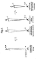
Figure 1 is a schematic diagram of a laser dazzler in accordance with this invention with provision to control the strength of the radiation incident on a target to ensure momentary dazzling but without causing permanent ocular damage and also with a stray detection system designed to ensure that the dazzle beam is reduced or inhibited should a secondary object, other than the target, approach the dazzle beam; -
Figure 2 is a schematic diagram of operation of the device showing continuous range monitoring and corresponding control of dazzle power, and -
Figure 3 is a schematic diagram of operation showing the stray detector system employing one or more secondary stray detection beams to detect objects at or approaching the periphery of the dazzle laser. - Referring initially to
Figure 1 , the laser dazzle system comprises adazzle laser 10 designed to emit abeam 11 of laser radiation designed to momentarily dazzle a human user. The strength of the laser beam (and in particular its intensity when received at the target) is adjustable by means of one or more of apower control unit 12, abeam attenuator modulator 14 and a variable beam expander 15, each being under the control of acentral controller 16. A laser range finder generally indicated at 18 comprises arange beam emitter 20 and arange beam receiver 22 each under the control of arange detector 23 which receives and processes signals from therange beam receiver 22 to determine the range of a target. Thelaser range finder 18 is controlled by thecentral controller 16 which also receives range data from therange detector 23. - The apparatus also includes one or more stray detector modules indicated generally at 26 comprising a stray
detection beam emitter 28 emitting astray detection beam 29, and a straybeam detection receiver 30. The stray detection beam emitter and the stray beam detection receiver are each under the control of astray detector 32 which controls them and processes the return information to identify when a stray secondary object is approaching the periphery of the beam emitted by the dazzle laser (or the periphery of the projected beam, if the dazzle laser is quiescent). Thestray detector 26 supplies data relating to stray secondary objects to the controller and is also controlled by thecontroller 16. As to be described in more detail below, the straydetection beam emitter 28 is provided with a beam shaper orbeam scanner unit 34. - Although the above embodiment includes a
range beam emitter 22 and a straydetection beam emitter 28 separately from thedazzle laser 10, in modified embodiments one or both may be omitted and the dazzle laser controlled to provided a range finder facility and/or a stray detection facility. For example, operation of thedazzle laser 10 and therange finder 18 andstray detectors 26 may effectively be multiplexed with the dazzle laser intermittently being modified in at least one of laser wavelength, intensity, divergence and beam shape to illuminate the field of view required and for the particular range finding, stray detecting or dazzling function. - In this arrangement, the
controller 16 uses therange finder 18 in order to measure the range to target and then subsequently sets the power of the dazzle laser before it is switched on. Following this, thecontroller 16 continuously monitors the indication of range determined by therange finder 18 and adjusts the power of thedazzle laser 10 accordingly. This therefore ensures that the optimum laser intensity is generated at the target range, whilst ensuring that the power does not exceed that which would produce permanent ocular damage (retinal damage). As referred to above, the controller may control the effective strength of the laser beam by one or more of the following ways. The laser output power may be adjusted usinglaser power control 12. The divergence of the dazzle laser beam (since it is the intensity (laser power per unit area) which needs to be controlled at the target range) may be adjusted using an adjustable beam expander 14 at the dazzle laser exit for this purpose. The laser range finder beam is required to be roughly equal to or less than the divergence of the dazzle laser beam in order to ensure that the dazzle power is set according to the laser range finder target. Avariable attenuator 15 may be used to attenuate the beam as required. - The dazzle process is illustrated schematically in
Figure 2 . Thus initially thelaser range finder 18 is used to measure the range to the required target. Thecontroller 18 then uses this information to set power of thedazzle laser 10 according to laser safety calculations from a suitable look up table or the like. Thedazzle laser 10 is then energised at the correct power momentarily to blind the target. The controller continuously monitors the range of the target and varies the dazzle power as necessary. The delay (t) between the laser range measurement acquisition and adjustment of the strength of the dazzle beam needs to be sufficiently short in order to prevent laser ocular overdose if the target moves towards the laser source. - Turning now to the anti-stray safety mechanism, given the laser intensity levels which could be present within 100 metres of the laser output aperture (particularly if the dazzle power is set for a target at, say, 1km) it is advantageous to have a mechanism whereby the system will either reduce dazzle laser power or shut the laser off completely in the event of a third party wandering inadvertently into the dazzle laser beam or, where the user of the device is swinging the device around to follow a target, where the dazzle laser beam inadvertently approaches a third party. In a basic system the operator may be required to maintain awareness of the environment immediately surrounding that of the laser trajectory. However, in the arrangement described below, a safety mechanism is provided to remove this responsibility from the operator.
- A stray detector module employing range finder technology is provided to monitor the periphery of the dazzle laser. The
stray detection beam 29 is co-bore sited with thedazzle beam 11, or positioned closely adjacent, but has a divergence much larger than that of the dazzle beam and operates at a different wavelength in order to avoid cross talk. The divergence of thestray detection beam 29 produces a cone which detects objects which are adjacent but currently outside the dazzle beam, as illustrated inFigure 3(a) . While thedazzle laser 11 is operating, the stray detector continuously monitors the area immediately surrounding thedazzle laser 11. If the stray detector detects a secondary object moving towards the centre of its beam (i.e. the location of the dazzle laser), then the dazzle laser power is immediately reduced or shut down until such time that the stray secondary object has moved on, or that the stray secondary object has become the new target. The acquisition process may then continue as normal. - The beam shape of the secondary
stray detection beam 29 may take various forms. In its simplest, a simple conic shape may be used (i.e. a Gaussian beam as inFigure 3(a) ) but it will be appreciated that such a beam will strike the ground after perhaps only a short distance. This may produce multiple ground reflections which may overload the stray detector receiver. - In a modification the stray
detector beam emitter 28 incorporates abeam shaper 34. In one arrangement, rather than using optics to uniformly diffract the stray detector beam, a cylindrical lens (or wedge shaped optic) or a grating is used in order to diffract the beam non-uniformly. Thus thebeam 29 is expanded in the horizontal plane but left essentially collimated (or at least of similar divergence to the dazzle beam) in the vertical plane. This produces a generally elliptical beam profile in the far-field. This is illustrated inFigure 3(b) . In another arrangement, shown inFigure 3(c) a plurality ofstray detectors 26 may be positioned either side of theprimary dazzle beam 11. Functionally, this is similar to the elliptical beam ofFigure 3(b) but provides a greater range capability because diffracting the beam will spread the energy over a larger area leading to a drop in maximum range capability. - In a yet further embodiment, a single stray detector beam emitter could be used with a
beam scanner 34 designed to continuously scan the pointing direction about the dazzle laser. - The divergence of the stray detector beam (or the angular deflection of the stray detector beam with respect to the primary dazzle beam) is determined by a trade off between the rate at which the combined system can determine that a stray (and not an inanimate object) has entered the field of view and set the dazzle laser power accordingly, and the reduction in maximum measurable range because of stray detector beam divergence. Thus the beam must be wide enough to detect a stray object in time to reduce dazzle power, but must be narrow enough to be useable at all practical ranges. In this respect it is advantageous that the region of highest dazzle power and therefore the region requiring the highest degree of power control is the range closest to the dazzle laser (0-100 metres). Beyond 100 to 200 metres, the change in dazzle power required for a target at, say, 500 metres compared to 800 metres, is very small.
- The central control includes suitable tracking and discrimination software so that apparatus can discriminate between the background scene and the target or potential targets. Such software is well known to one skilled in the art and will not be described in detail here. Typically, such software may analyse a viewed scene to identify those elements that are moving in the scene. In addition, where the apparatus is designed to be moved itself the software will discount movement due to the change in viewing direction and still analyse for objects moving relative to the background scenery.
- In a yet further embodiment, the controller may be adapted to allow a user to designate a target in the viewed scene and for the control unit to steer the dazzle beam to track a target. Again, such software algorithms are well known to those skilled in the art and will not be described in detail here. In this arrangement the detection axes of the range finger and the stray detector may be moved to follow the axis of the dazzle laser.
- The device described herein may be used in a number of different applications but typically will be a portable unit. For example, the unit may be mounted on a rifle, a tripod or a vehicle.
Claims (14)
- A dazzle apparatus comprising:a radiation source (10) for emitting a dazzle beam (11) of radiation towards a target to be dazzled, the target being at a variable range, a beam control system (16, 12, 14, 15) to control the strength of the dazzle beam in accordance with the range of said target to deliver to said target radiation of sufficient intensity momentarily to dazzle a user, and a stray detector (26) for detecting approach of a secondary object towards said dazzle beam (11), or vice versa and, in response to such approach, to reduce the strength of or inhibit the beam.
- A dazzle apparatus according to Claim 1, wherein the radiation source (10) emits a beam of laser radiation.
- A dazzle apparatus according to Claim 1 or Claim 2, which includes a range finger (18) operable to determine the range of a target.
- A dazzle apparatus according to Claim 3, wherein the range finder (18) is a laser range finder.
- A dazzle apparatus according to Claim 4, wherein the range finder includes a range finder receiver (22) operable to detect and process radiation from said radiation source reflected by said target thereby to determine the range of the target.
- A dazzle apparatus according to Claim 4, which includes a separate range finder source (20) for emitting a range beam of radiation towards said target and the range finder is operable to detect and process radiation from said range beam of radiation reflected by said target thereby to detect said range.
- A dazzle apparatus according to any of the preceding Claims, wherein the beam control system (16, 12) varies the strength of the beam by adjusting the power of the radiation source, and/or by adjusting the divergence of the beam.
- A dazzle apparatus according to any of Claims 1 to 6, wherein said beam control means (16, 15) comprises an attenuator for variably attenuating said beam to vary the strength of the radiation at said target.
- A dazzle apparatus according to any preceding Claim, wherein said stray detector (26) includes a stray detector source (28) for emitting at least one stray detection beam (29) to illuminate an area adjacent said dazzle beam (11), and a stray detection receiver (30) for detecting and processing radiation reflected by said at least one secondary object to determine a position of the secondary object relative to the dazzle beam.
- A dazzle apparatus according to Claim 9, wherein said stray detector source (28) includes a beam shaper (34) whereby the stray detection beam has a flattened shape in which the beam divergence in one plane is similar to that of the dazzle beam and is significantly greater in a perpendicular plane.
- A dazzle apparatus according to Claim 9, wherein said stray detector source (28) emits a plurality of stray detection beams (29) each disposed to illuminate a respective area adjacent said dazzle beam (11).
- A dazzle apparatus according to Claim 9, wherein said stray detector source (28) is operable to scan one or more stray detector beams (29) across an area adjacent the dazzle beam (11).
- A dazzle apparatus according to any preceding Claim, wherein said stray detector (26) is operable to track the position of a secondary object and to predict the trajectory thereof, and said beam control system (16) is operable to reduce the strength of, or inhibit, the dazzle beam if the predicted trajectory passes through, or within a preset distance of, the dazzle beam.
- A dazzle apparatus according to any preceding Claim, wherein the beam control system (16) is also operable to control the angular position of the dazzle beam (11), and which further includes a target tracker operable on acquisition or designation of a target to provide to said beam control system data to enable the controller to lock the dazzle beam on the target.
Applications Claiming Priority (2)
| Application Number | Priority Date | Filing Date | Title |
|---|---|---|---|
| GBGB1005467.4A GB201005467D0 (en) | 2010-03-31 | 2010-03-31 | Dazzlers |
| PCT/GB2011/050572 WO2011121333A1 (en) | 2010-03-31 | 2011-03-23 | Dazzlers |
Publications (2)
| Publication Number | Publication Date |
|---|---|
| EP2553379A1 EP2553379A1 (en) | 2013-02-06 |
| EP2553379B1 true EP2553379B1 (en) | 2014-01-01 |
Family
ID=42228718
Family Applications (1)
| Application Number | Title | Priority Date | Filing Date |
|---|---|---|---|
| EP11712305.9A Active EP2553379B1 (en) | 2010-03-31 | 2011-03-23 | Dazzlers |
Country Status (6)
| Country | Link |
|---|---|
| US (1) | US20130016514A1 (en) |
| EP (1) | EP2553379B1 (en) |
| AU (1) | AU2011234207B2 (en) |
| ES (1) | ES2448420T3 (en) |
| GB (1) | GB201005467D0 (en) |
| WO (1) | WO2011121333A1 (en) |
Families Citing this family (9)
| Publication number | Priority date | Publication date | Assignee | Title |
|---|---|---|---|---|
| CN103688157A (en) * | 2011-05-12 | 2014-03-26 | 阿拉基防御系统公司 | Optical hazard avoidance device and method |
| US9928930B1 (en) * | 2013-01-25 | 2018-03-27 | The Boeing Company | Laser illuminating system and method for selectively illuminating a zone of coverage |
| FR3039287B1 (en) | 2015-07-22 | 2020-03-27 | Arianegroup Sas | METHOD AND DEVICE FOR SECURING A SPACE CROSSED BY A HIGH POWER LASER BEAM |
| US20180347752A1 (en) * | 2015-11-25 | 2018-12-06 | VHS IP Pty Ltd | Worksite safety device using lidar |
| DE102017100068A1 (en) * | 2017-01-04 | 2018-07-05 | Rheinmetall Waffe Munition Gmbh | Laser system with protective device |
| US11561294B2 (en) | 2018-07-27 | 2023-01-24 | Vision Engineering Solutions, LLC | Laser safety system |
| KR102139670B1 (en) * | 2020-03-04 | 2020-07-30 | 국방과학연구소 | Laser dazzling effectiveness measuring apparatus and method |
| DE102020119620B4 (en) * | 2020-07-24 | 2024-02-08 | Rheinmetall Waffe Munition Gmbh | Methods and devices for reducing minimum eye safety distances in connection with illumination laser radiation |
| IL304087A (en) * | 2020-12-28 | 2023-08-01 | Plx Inc | Integrated tracking laser defense system and method |
Family Cites Families (18)
| Publication number | Priority date | Publication date | Assignee | Title |
|---|---|---|---|---|
| FR2378318A1 (en) * | 1977-01-21 | 1978-08-18 | Thomson Csf | MOBILE TARGET TRACKING SYSTEM |
| DE4444636A1 (en) * | 1994-12-15 | 1996-06-20 | Sepp Gunther | Weapon system for a glare laser |
| DE4444637C2 (en) * | 1994-12-15 | 1996-09-26 | Sepp Gunther | Laser weapon system |
| US5784023A (en) * | 1995-06-26 | 1998-07-21 | Bluege; John | Speed detection method |
| US5685636A (en) * | 1995-08-23 | 1997-11-11 | Science And Engineering Associates, Inc. | Eye safe laser security device |
| US5997163A (en) * | 1998-06-09 | 1999-12-07 | L E Systems Inc. | Mobile laser spotlight system for law enforcement |
| US20030193805A1 (en) * | 2002-04-10 | 2003-10-16 | Matheson Michael R. | Method and apparatus for dispersing different genera of birds |
| US7550725B2 (en) * | 2003-06-16 | 2009-06-23 | White Box, Inc. | Multi-laser system |
| EP1642084A1 (en) * | 2003-07-03 | 2006-04-05 | Optris GmbH | Visiereinrichtung und vorrichtung mit einer kontaktlos oder kontaktbehaftet einsetzbaren mess-, arbeits- und/oder wirkeinrichtung |
| US7537381B2 (en) * | 2003-12-02 | 2009-05-26 | White Box, Inc. | Measurement system and method |
| US7040780B2 (en) * | 2004-02-20 | 2006-05-09 | General Dynamics Armament And Technical Products | Laser dazzler matrix |
| US20060234191A1 (en) * | 2005-04-15 | 2006-10-19 | Ludman Jacques E | Auto-aiming dazzler |
| US20090040764A1 (en) * | 2005-09-21 | 2009-02-12 | Thales Holdings Uk Plc | Method and apparatus for inducing dazzle |
| US8051761B1 (en) * | 2007-11-16 | 2011-11-08 | The Boeing Company | System and methods for broad area visual obscuration |
| US8203698B2 (en) * | 2008-02-28 | 2012-06-19 | B.E. Meyers & Co. Inc. | Control modules for laser systems having auto-ranging and control capability |
| US20100172136A1 (en) * | 2008-11-17 | 2010-07-08 | Williamson Iii Robert S | Compact non-lethal optical disruption device |
| US8089617B2 (en) * | 2009-01-21 | 2012-01-03 | Raytheon Company | Energy efficient laser detection and ranging system |
| DE112011100909T5 (en) * | 2010-03-16 | 2013-01-17 | Pvb Holdings Llc | Laser blinding gun |
-
2010
- 2010-03-31 GB GBGB1005467.4A patent/GB201005467D0/en not_active Ceased
-
2011
- 2011-03-23 EP EP11712305.9A patent/EP2553379B1/en active Active
- 2011-03-23 WO PCT/GB2011/050572 patent/WO2011121333A1/en active Application Filing
- 2011-03-23 AU AU2011234207A patent/AU2011234207B2/en active Active
- 2011-03-23 US US13/638,158 patent/US20130016514A1/en not_active Abandoned
- 2011-03-23 ES ES11712305.9T patent/ES2448420T3/en active Active
Also Published As
| Publication number | Publication date |
|---|---|
| AU2011234207A1 (en) | 2012-10-25 |
| ES2448420T3 (en) | 2014-03-13 |
| EP2553379A1 (en) | 2013-02-06 |
| WO2011121333A1 (en) | 2011-10-06 |
| US20130016514A1 (en) | 2013-01-17 |
| GB201005467D0 (en) | 2010-05-19 |
| AU2011234207B2 (en) | 2014-01-16 |
Similar Documents
| Publication | Publication Date | Title |
|---|---|---|
| EP2553379B1 (en) | Dazzlers | |
| US11923694B2 (en) | Remote power safety system | |
| JP3148724B2 (en) | Shared aperture dichroic active tracker with background subtraction function | |
| US20110103410A1 (en) | Laser beam control system and method | |
| US20090219961A1 (en) | Laser Systems and Methods Having Auto-Ranging and Control Capability | |
| WO2020131217A3 (en) | Methods and systems for mapping retroreflectors | |
| US5336899A (en) | Adjustable near infrared rangefinder illuminator | |
| JPH11153398A (en) | Dichronism performance tracking device | |
| US10320141B2 (en) | Hard target detection for optical systems | |
| US20210215801A1 (en) | Eye-safe lidar system having an adjustable scanning range | |
| JP2019128145A5 (en) | ||
| US10578717B2 (en) | Dimmable glass for eye safety for LiDAR technology | |
| KR20180130480A (en) | Optical transmitting and receiving device and method | |
| EP3011255B1 (en) | Gated conjugation laser | |
| KR102103825B1 (en) | Identification of friend or foe apparatus for personal combat system | |
| WO2020096656A2 (en) | Active partial-beam alignment systems for sensor-to-laser boresight maintenance | |
| US11900562B2 (en) | Super-resolution automatic target aimpoint recognition and tracking | |
| KR102103827B1 (en) | Identification of friend or foe apparatus for personal combat system | |
| EP2051101B1 (en) | Optical sensor assembly and method for optical detection of objects | |
| KR102103826B1 (en) | Method for driving identification of friend or foe apparatus for personal combat system | |
| EP4115137A1 (en) | Plasma burst application system and method | |
| US8634065B2 (en) | Method for operating a jamming laser in a DIRCM system in a manner that is safe for eyes | |
| CN107101535B (en) | Emit the cokes control system such as laser and target acquisition light | |
| KR102262831B1 (en) | Common optical system for small gimbal type | |
| US20230184519A1 (en) | Safety assembly |
Legal Events
| Date | Code | Title | Description |
|---|---|---|---|
| PUAI | Public reference made under article 153(3) epc to a published international application that has entered the european phase |
Free format text: ORIGINAL CODE: 0009012 |
|
| 17P | Request for examination filed |
Effective date: 20120926 |
|
| AK | Designated contracting states |
Kind code of ref document: A1 Designated state(s): AL AT BE BG CH CY CZ DE DK EE ES FI FR GB GR HR HU IE IS IT LI LT LU LV MC MK MT NL NO PL PT RO RS SE SI SK SM TR |
|
| DAX | Request for extension of the european patent (deleted) | ||
| GRAP | Despatch of communication of intention to grant a patent |
Free format text: ORIGINAL CODE: EPIDOSNIGR1 |
|
| INTG | Intention to grant announced |
Effective date: 20130826 |
|
| GRAS | Grant fee paid |
Free format text: ORIGINAL CODE: EPIDOSNIGR3 |
|
| GRAA | (expected) grant |
Free format text: ORIGINAL CODE: 0009210 |
|
| AK | Designated contracting states |
Kind code of ref document: B1 Designated state(s): AL AT BE BG CH CY CZ DE DK EE ES FI FR GB GR HR HU IE IS IT LI LT LU LV MC MK MT NL NO PL PT RO RS SE SI SK SM TR |
|
| REG | Reference to a national code |
Ref country code: GB Ref legal event code: FG4D |
|
| RIN1 | Information on inventor provided before grant (corrected) |
Inventor name: STACEY, CRAIG, DANIEL Inventor name: CHARLTON, DAVID, WESLEY |
|
| REG | Reference to a national code |
Ref country code: CH Ref legal event code: EP |
|
| REG | Reference to a national code |
Ref country code: IE Ref legal event code: FG4D |
|
| REG | Reference to a national code |
Ref country code: DE Ref legal event code: R096 Ref document number: 602011004475 Country of ref document: DE Effective date: 20140213 |
|
| REG | Reference to a national code |
Ref country code: AT Ref legal event code: REF Ref document number: 647783 Country of ref document: AT Kind code of ref document: T Effective date: 20140215 |
|
| REG | Reference to a national code |
Ref country code: ES Ref legal event code: FG2A Ref document number: 2448420 Country of ref document: ES Kind code of ref document: T3 Effective date: 20140313 |
|
| REG | Reference to a national code |
Ref country code: NL Ref legal event code: VDEP Effective date: 20140101 |
|
| REG | Reference to a national code |
Ref country code: AT Ref legal event code: MK05 Ref document number: 647783 Country of ref document: AT Kind code of ref document: T Effective date: 20140101 |
|
| REG | Reference to a national code |
Ref country code: LT Ref legal event code: MG4D |
|
| PG25 | Lapsed in a contracting state [announced via postgrant information from national office to epo] |
Ref country code: LT Free format text: LAPSE BECAUSE OF FAILURE TO SUBMIT A TRANSLATION OF THE DESCRIPTION OR TO PAY THE FEE WITHIN THE PRESCRIBED TIME-LIMIT Effective date: 20140101 Ref country code: IS Free format text: LAPSE BECAUSE OF FAILURE TO SUBMIT A TRANSLATION OF THE DESCRIPTION OR TO PAY THE FEE WITHIN THE PRESCRIBED TIME-LIMIT Effective date: 20140501 |
|
| PG25 | Lapsed in a contracting state [announced via postgrant information from national office to epo] |
Ref country code: NL Free format text: LAPSE BECAUSE OF FAILURE TO SUBMIT A TRANSLATION OF THE DESCRIPTION OR TO PAY THE FEE WITHIN THE PRESCRIBED TIME-LIMIT Effective date: 20140101 Ref country code: SE Free format text: LAPSE BECAUSE OF FAILURE TO SUBMIT A TRANSLATION OF THE DESCRIPTION OR TO PAY THE FEE WITHIN THE PRESCRIBED TIME-LIMIT Effective date: 20140101 Ref country code: FI Free format text: LAPSE BECAUSE OF FAILURE TO SUBMIT A TRANSLATION OF THE DESCRIPTION OR TO PAY THE FEE WITHIN THE PRESCRIBED TIME-LIMIT Effective date: 20140101 Ref country code: CY Free format text: LAPSE BECAUSE OF FAILURE TO SUBMIT A TRANSLATION OF THE DESCRIPTION OR TO PAY THE FEE WITHIN THE PRESCRIBED TIME-LIMIT Effective date: 20140101 Ref country code: AT Free format text: LAPSE BECAUSE OF FAILURE TO SUBMIT A TRANSLATION OF THE DESCRIPTION OR TO PAY THE FEE WITHIN THE PRESCRIBED TIME-LIMIT Effective date: 20140101 Ref country code: PT Free format text: LAPSE BECAUSE OF FAILURE TO SUBMIT A TRANSLATION OF THE DESCRIPTION OR TO PAY THE FEE WITHIN THE PRESCRIBED TIME-LIMIT Effective date: 20140502 |
|
| PG25 | Lapsed in a contracting state [announced via postgrant information from national office to epo] |
Ref country code: HR Free format text: LAPSE BECAUSE OF FAILURE TO SUBMIT A TRANSLATION OF THE DESCRIPTION OR TO PAY THE FEE WITHIN THE PRESCRIBED TIME-LIMIT Effective date: 20140101 Ref country code: RS Free format text: LAPSE BECAUSE OF FAILURE TO SUBMIT A TRANSLATION OF THE DESCRIPTION OR TO PAY THE FEE WITHIN THE PRESCRIBED TIME-LIMIT Effective date: 20140101 Ref country code: LV Free format text: LAPSE BECAUSE OF FAILURE TO SUBMIT A TRANSLATION OF THE DESCRIPTION OR TO PAY THE FEE WITHIN THE PRESCRIBED TIME-LIMIT Effective date: 20140101 Ref country code: BE Free format text: LAPSE BECAUSE OF FAILURE TO SUBMIT A TRANSLATION OF THE DESCRIPTION OR TO PAY THE FEE WITHIN THE PRESCRIBED TIME-LIMIT Effective date: 20140101 |
|
| REG | Reference to a national code |
Ref country code: DE Ref legal event code: R097 Ref document number: 602011004475 Country of ref document: DE |
|
| PG25 | Lapsed in a contracting state [announced via postgrant information from national office to epo] |
Ref country code: EE Free format text: LAPSE BECAUSE OF FAILURE TO SUBMIT A TRANSLATION OF THE DESCRIPTION OR TO PAY THE FEE WITHIN THE PRESCRIBED TIME-LIMIT Effective date: 20140101 Ref country code: CZ Free format text: LAPSE BECAUSE OF FAILURE TO SUBMIT A TRANSLATION OF THE DESCRIPTION OR TO PAY THE FEE WITHIN THE PRESCRIBED TIME-LIMIT Effective date: 20140101 Ref country code: DK Free format text: LAPSE BECAUSE OF FAILURE TO SUBMIT A TRANSLATION OF THE DESCRIPTION OR TO PAY THE FEE WITHIN THE PRESCRIBED TIME-LIMIT Effective date: 20140101 Ref country code: LU Free format text: LAPSE BECAUSE OF FAILURE TO SUBMIT A TRANSLATION OF THE DESCRIPTION OR TO PAY THE FEE WITHIN THE PRESCRIBED TIME-LIMIT Effective date: 20140323 Ref country code: RO Free format text: LAPSE BECAUSE OF FAILURE TO SUBMIT A TRANSLATION OF THE DESCRIPTION OR TO PAY THE FEE WITHIN THE PRESCRIBED TIME-LIMIT Effective date: 20140101 |
|
| REG | Reference to a national code |
Ref country code: CH Ref legal event code: PL |
|
| PLBE | No opposition filed within time limit |
Free format text: ORIGINAL CODE: 0009261 |
|
| STAA | Information on the status of an ep patent application or granted ep patent |
Free format text: STATUS: NO OPPOSITION FILED WITHIN TIME LIMIT |
|
| PG25 | Lapsed in a contracting state [announced via postgrant information from national office to epo] |
Ref country code: SK Free format text: LAPSE BECAUSE OF FAILURE TO SUBMIT A TRANSLATION OF THE DESCRIPTION OR TO PAY THE FEE WITHIN THE PRESCRIBED TIME-LIMIT Effective date: 20140101 Ref country code: PL Free format text: LAPSE BECAUSE OF FAILURE TO SUBMIT A TRANSLATION OF THE DESCRIPTION OR TO PAY THE FEE WITHIN THE PRESCRIBED TIME-LIMIT Effective date: 20140101 |
|
| 26N | No opposition filed |
Effective date: 20141002 |
|
| REG | Reference to a national code |
Ref country code: IE Ref legal event code: MM4A |
|
| REG | Reference to a national code |
Ref country code: DE Ref legal event code: R097 Ref document number: 602011004475 Country of ref document: DE Effective date: 20141002 |
|
| PG25 | Lapsed in a contracting state [announced via postgrant information from national office to epo] |
Ref country code: IE Free format text: LAPSE BECAUSE OF NON-PAYMENT OF DUE FEES Effective date: 20140323 Ref country code: LI Free format text: LAPSE BECAUSE OF NON-PAYMENT OF DUE FEES Effective date: 20140331 Ref country code: CH Free format text: LAPSE BECAUSE OF NON-PAYMENT OF DUE FEES Effective date: 20140331 |
|
| PG25 | Lapsed in a contracting state [announced via postgrant information from national office to epo] |
Ref country code: SI Free format text: LAPSE BECAUSE OF FAILURE TO SUBMIT A TRANSLATION OF THE DESCRIPTION OR TO PAY THE FEE WITHIN THE PRESCRIBED TIME-LIMIT Effective date: 20140101 |
|
| PG25 | Lapsed in a contracting state [announced via postgrant information from national office to epo] |
Ref country code: MT Free format text: LAPSE BECAUSE OF FAILURE TO SUBMIT A TRANSLATION OF THE DESCRIPTION OR TO PAY THE FEE WITHIN THE PRESCRIBED TIME-LIMIT Effective date: 20140101 |
|
| REG | Reference to a national code |
Ref country code: FR Ref legal event code: PLFP Year of fee payment: 6 |
|
| PG25 | Lapsed in a contracting state [announced via postgrant information from national office to epo] |
Ref country code: SM Free format text: LAPSE BECAUSE OF FAILURE TO SUBMIT A TRANSLATION OF THE DESCRIPTION OR TO PAY THE FEE WITHIN THE PRESCRIBED TIME-LIMIT Effective date: 20140101 Ref country code: NO Free format text: LAPSE BECAUSE OF FAILURE TO SUBMIT A TRANSLATION OF THE DESCRIPTION OR TO PAY THE FEE WITHIN THE PRESCRIBED TIME-LIMIT Effective date: 20140401 |
|
| PGFP | Annual fee paid to national office [announced via postgrant information from national office to epo] |
Ref country code: ES Payment date: 20160309 Year of fee payment: 6 |
|
| PG25 | Lapsed in a contracting state [announced via postgrant information from national office to epo] |
Ref country code: MC Free format text: LAPSE BECAUSE OF FAILURE TO SUBMIT A TRANSLATION OF THE DESCRIPTION OR TO PAY THE FEE WITHIN THE PRESCRIBED TIME-LIMIT Effective date: 20140101 |
|
| PG25 | Lapsed in a contracting state [announced via postgrant information from national office to epo] |
Ref country code: BG Free format text: LAPSE BECAUSE OF FAILURE TO SUBMIT A TRANSLATION OF THE DESCRIPTION OR TO PAY THE FEE WITHIN THE PRESCRIBED TIME-LIMIT Effective date: 20140101 Ref country code: GR Free format text: LAPSE BECAUSE OF FAILURE TO SUBMIT A TRANSLATION OF THE DESCRIPTION OR TO PAY THE FEE WITHIN THE PRESCRIBED TIME-LIMIT Effective date: 20140402 |
|
| PG25 | Lapsed in a contracting state [announced via postgrant information from national office to epo] |
Ref country code: HU Free format text: LAPSE BECAUSE OF FAILURE TO SUBMIT A TRANSLATION OF THE DESCRIPTION OR TO PAY THE FEE WITHIN THE PRESCRIBED TIME-LIMIT; INVALID AB INITIO Effective date: 20110323 Ref country code: TR Free format text: LAPSE BECAUSE OF FAILURE TO SUBMIT A TRANSLATION OF THE DESCRIPTION OR TO PAY THE FEE WITHIN THE PRESCRIBED TIME-LIMIT Effective date: 20140101 |
|
| PGFP | Annual fee paid to national office [announced via postgrant information from national office to epo] |
Ref country code: IT Payment date: 20160324 Year of fee payment: 6 |
|
| REG | Reference to a national code |
Ref country code: FR Ref legal event code: PLFP Year of fee payment: 7 |
|
| PG25 | Lapsed in a contracting state [announced via postgrant information from national office to epo] |
Ref country code: IT Free format text: LAPSE BECAUSE OF NON-PAYMENT OF DUE FEES Effective date: 20170323 |
|
| REG | Reference to a national code |
Ref country code: FR Ref legal event code: PLFP Year of fee payment: 8 |
|
| PG25 | Lapsed in a contracting state [announced via postgrant information from national office to epo] |
Ref country code: MK Free format text: LAPSE BECAUSE OF FAILURE TO SUBMIT A TRANSLATION OF THE DESCRIPTION OR TO PAY THE FEE WITHIN THE PRESCRIBED TIME-LIMIT Effective date: 20140101 |
|
| REG | Reference to a national code |
Ref country code: ES Ref legal event code: FD2A Effective date: 20180705 |
|
| PG25 | Lapsed in a contracting state [announced via postgrant information from national office to epo] |
Ref country code: ES Free format text: LAPSE BECAUSE OF NON-PAYMENT OF DUE FEES Effective date: 20170324 |
|
| PG25 | Lapsed in a contracting state [announced via postgrant information from national office to epo] |
Ref country code: AL Free format text: LAPSE BECAUSE OF FAILURE TO SUBMIT A TRANSLATION OF THE DESCRIPTION OR TO PAY THE FEE WITHIN THE PRESCRIBED TIME-LIMIT Effective date: 20140101 |
|
| PGFP | Annual fee paid to national office [announced via postgrant information from national office to epo] |
Ref country code: FR Payment date: 20230222 Year of fee payment: 13 |
|
| PGFP | Annual fee paid to national office [announced via postgrant information from national office to epo] |
Ref country code: GB Payment date: 20230221 Year of fee payment: 13 Ref country code: DE Payment date: 20230221 Year of fee payment: 13 |