EP2553379B1 - Blender - Google Patents
Blender Download PDFInfo
- Publication number
- EP2553379B1 EP2553379B1 EP11712305.9A EP11712305A EP2553379B1 EP 2553379 B1 EP2553379 B1 EP 2553379B1 EP 11712305 A EP11712305 A EP 11712305A EP 2553379 B1 EP2553379 B1 EP 2553379B1
- Authority
- EP
- European Patent Office
- Prior art keywords
- dazzle
- target
- stray
- range
- radiation
- Prior art date
- Legal status (The legal status is an assumption and is not a legal conclusion. Google has not performed a legal analysis and makes no representation as to the accuracy of the status listed.)
- Active
Links
- 230000005855 radiation Effects 0.000 claims description 24
- 238000001514 detection method Methods 0.000 claims description 21
- 238000013459 approach Methods 0.000 claims description 6
- 238000000034 method Methods 0.000 claims description 6
- 230000008569 process Effects 0.000 claims description 6
- 238000012545 processing Methods 0.000 claims description 2
- 230000004044 response Effects 0.000 claims description 2
- 238000010586 diagram Methods 0.000 description 3
- 230000007246 mechanism Effects 0.000 description 3
- 238000004458 analytical method Methods 0.000 description 2
- 230000008859 change Effects 0.000 description 2
- 230000001427 coherent effect Effects 0.000 description 2
- 238000012544 monitoring process Methods 0.000 description 2
- 241001465754 Metazoa Species 0.000 description 1
- 206010057430 Retinal injury Diseases 0.000 description 1
- 230000003044 adaptive effect Effects 0.000 description 1
- 230000002238 attenuated effect Effects 0.000 description 1
- 238000005516 engineering process Methods 0.000 description 1
- 230000002401 inhibitory effect Effects 0.000 description 1
- 238000005259 measurement Methods 0.000 description 1
- 230000004048 modification Effects 0.000 description 1
- 238000012986 modification Methods 0.000 description 1
- 230000009467 reduction Effects 0.000 description 1
- 230000000007 visual effect Effects 0.000 description 1
Images


Classifications
-
- F—MECHANICAL ENGINEERING; LIGHTING; HEATING; WEAPONS; BLASTING
- F41—WEAPONS
- F41H—ARMOUR; ARMOURED TURRETS; ARMOURED OR ARMED VEHICLES; MEANS OF ATTACK OR DEFENCE, e.g. CAMOUFLAGE, IN GENERAL
- F41H13/00—Means of attack or defence not otherwise provided for
- F41H13/0043—Directed energy weapons, i.e. devices that direct a beam of high energy content toward a target for incapacitating or destroying the target
- F41H13/005—Directed energy weapons, i.e. devices that direct a beam of high energy content toward a target for incapacitating or destroying the target the high-energy beam being a laser beam
- F41H13/0056—Directed energy weapons, i.e. devices that direct a beam of high energy content toward a target for incapacitating or destroying the target the high-energy beam being a laser beam for blinding or dazzling, i.e. by overstimulating the opponent's eyes or the enemy's sensor equipment
-
- F—MECHANICAL ENGINEERING; LIGHTING; HEATING; WEAPONS; BLASTING
- F41—WEAPONS
- F41H—ARMOUR; ARMOURED TURRETS; ARMOURED OR ARMED VEHICLES; MEANS OF ATTACK OR DEFENCE, e.g. CAMOUFLAGE, IN GENERAL
- F41H13/00—Means of attack or defence not otherwise provided for
- F41H13/0043—Directed energy weapons, i.e. devices that direct a beam of high energy content toward a target for incapacitating or destroying the target
- F41H13/0087—Directed energy weapons, i.e. devices that direct a beam of high energy content toward a target for incapacitating or destroying the target the high-energy beam being a bright light, e.g. for dazzling or blinding purposes
Definitions
- This invention relates to dazzlers.
- a dazzler is used to emit a beam of high intensity radiation, usually laser, towards a human or animal target temporarily to blind the target or to provide visual distraction or a warning.
- Typical existing dazzle lasers are of fixed power which places a lower limit on the nominal ocular hazard distance (that is the distance at which the laser becomes eye safe) and therefore the range over which the device is of use. This requires user judgment and, in order to have a practical minimum range, limits the laser power and therefore the upper range limit a laser dazzler is known from US 2005/0185403
- this invention provides a dazzle apparatus comprising a radiation source for emitting a dazzle beam of radiation towards a target to be dazzled, the target being at a variable range, a beam control system to control the strength of the dazzle beam in accordance with the range of said target to deliver to said target radiation of sufficient intensity momentarily to dazzle a user, and a stray detector for detecting approach of a secondary object towards said dazzle beam, or vice versa and, in response to such approach, to reduce the strength of or inhibit the beam.
- the dazzle apparatus modulates the strength of the radiation to ensure that the beam is effective to dazzle the target without causing permanent ocular damage, thereby potentially increasing the range over which the dazzler may be effectively used and prevents inadvertent incidence of the dazzle beam on a secondary target which moves towards the dazzle beam or towards which the dazzle beam moves.
- the device may receive target range data from an external device or more preferably from a range finder associated with the dazzler.
- the range finder may conveniently be a laser range finder.
- the range finder may use reflections of the dazzle laser suitably attenuated if required to determine the range of the target, or it could use a separate laser.
- the beam control may adjust the strength of the beam by adjusting the source power, by attenuating the beam using e.g. an acousto-optic modulator, or it may adjust the strength of the beam by adjusting the divergence of the beam so as to adjust the intensity or laser power per unit area.
- the divergence of the beam of radiation may be adjusted by means of an adjustable beam expander.
- the stray detector may include a stray detection beam source for emitting at least one stray detection beam to illuminate an area adjacent said dazzle beam and a stray detection receiver for detecting and processing radiation reflected by said at least one secondary object to determine a position of the secondary object relative to the dazzle beam.
- the stray detector source includes a beam shaper whereby the stray detector beam has a flattened shape in which the beam divergence in one plane is similar to that of the dazzle beam and is significantly greater in a perpendicular plane.
- the beam shaper may be a lens or grating.
- said stray detector source may emit a plurality of stray detector beams each disposed to illuminate a respective area adjacent said dazzle beam. These may be from a single source or a plurality of sources. In another arrangement said stray detector source may be operable to scan one or more stray detector beams across an area adjacent the dazzle beam.
- the stray detector may be operable to track the position of a secondary object and to predict the trajectory thereof, with said beam control system being operable to reduce the strength of, or inhibit, the dazzle beam if the predicted trajectory passes through, or within a preset distance of, the dazzle beam.
- the beam control system may be operable also to control the angular position of the dazzle beam, and may include a target tracker operable on acquisition or designation of a target to provide to said beam control system data to enable the beam control to lock the dazzle beam on the target.
- the beam control also steers the stray detector beam and the range finder beam if these are separate.
- this invention provides a dazzle apparatus comprising a radiation source for emitting a dazzle beam to dazzle a target, a stray detector for monitoring an area near said dazzle beam and for inhibiting or reducing the strength of said dazzle beam, on detecting a secondary object adjacent the periphery of said dazzle beam.
- the laser dazzle system comprises a dazzle laser 10 designed to emit a beam 11 of laser radiation designed to momentarily dazzle a human user.
- the strength of the laser beam (and in particular its intensity when received at the target) is adjustable by means of one or more of a power control unit 12, a beam attenuator modulator 14 and a variable beam expander 15, each being under the control of a central controller 16.
- a laser range finder generally indicated at 18 comprises a range beam emitter 20 and a range beam receiver 22 each under the control of a range detector 23 which receives and processes signals from the range beam receiver 22 to determine the range of a target.
- the laser range finder 18 is controlled by the central controller 16 which also receives range data from the range detector 23.
- the apparatus also includes one or more stray detector modules indicated generally at 26 comprising a stray detection beam emitter 28 emitting a stray detection beam 29, and a stray beam detection receiver 30.
- the stray detection beam emitter and the stray beam detection receiver are each under the control of a stray detector 32 which controls them and processes the return information to identify when a stray secondary object is approaching the periphery of the beam emitted by the dazzle laser (or the periphery of the projected beam, if the dazzle laser is quiescent).
- the stray detector 26 supplies data relating to stray secondary objects to the controller and is also controlled by the controller 16.
- the stray detection beam emitter 28 is provided with a beam shaper or beam scanner unit 34.
- the above embodiment includes a range beam emitter 22 and a stray detection beam emitter 28 separately from the dazzle laser 10, in modified embodiments one or both may be omitted and the dazzle laser controlled to provided a range finder facility and/or a stray detection facility.
- operation of the dazzle laser 10 and the range finder 18 and stray detectors 26 may effectively be multiplexed with the dazzle laser intermittently being modified in at least one of laser wavelength, intensity, divergence and beam shape to illuminate the field of view required and for the particular range finding, stray detecting or dazzling function.
- the controller 16 uses the range finder 18 in order to measure the range to target and then subsequently sets the power of the dazzle laser before it is switched on. Following this, the controller 16 continuously monitors the indication of range determined by the range finder 18 and adjusts the power of the dazzle laser 10 accordingly. This therefore ensures that the optimum laser intensity is generated at the target range, whilst ensuring that the power does not exceed that which would produce permanent ocular damage (retinal damage).
- the controller may control the effective strength of the laser beam by one or more of the following ways.
- the laser output power may be adjusted using laser power control 12.
- the divergence of the dazzle laser beam (since it is the intensity (laser power per unit area) which needs to be controlled at the target range) may be adjusted using an adjustable beam expander 14 at the dazzle laser exit for this purpose.
- the laser range finder beam is required to be roughly equal to or less than the divergence of the dazzle laser beam in order to ensure that the dazzle power is set according to the laser range finder target.
- a variable attenuator 15 may be used to attenuate the beam as required.
- the dazzle process is illustrated schematically in Figure 2 .
- the laser range finder 18 is used to measure the range to the required target.
- the controller 18 uses this information to set power of the dazzle laser 10 according to laser safety calculations from a suitable look up table or the like.
- the dazzle laser 10 is then energised at the correct power momentarily to blind the target.
- the controller continuously monitors the range of the target and varies the dazzle power as necessary.
- the delay (t) between the laser range measurement acquisition and adjustment of the strength of the dazzle beam needs to be sufficiently short in order to prevent laser ocular overdose if the target moves towards the laser source.
- the anti-stray safety mechanism given the laser intensity levels which could be present within 100 metres of the laser output aperture (particularly if the dazzle power is set for a target at, say, 1km) it is advantageous to have a mechanism whereby the system will either reduce dazzle laser power or shut the laser off completely in the event of a third party wandering inadvertently into the dazzle laser beam or, where the user of the device is swinging the device around to follow a target, where the dazzle laser beam inadvertently approaches a third party.
- the operator may be required to maintain awareness of the environment immediately surrounding that of the laser trajectory.
- a safety mechanism is provided to remove this responsibility from the operator.
- a stray detector module employing range finder technology is provided to monitor the periphery of the dazzle laser.
- the stray detection beam 29 is co-bore sited with the dazzle beam 11, or positioned closely adjacent, but has a divergence much larger than that of the dazzle beam and operates at a different wavelength in order to avoid cross talk.
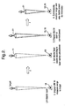
- the divergence of the stray detection beam 29 produces a cone which detects objects which are adjacent but currently outside the dazzle beam, as illustrated in Figure 3(a) .
- the stray detector While the dazzle laser 11 is operating, the stray detector continuously monitors the area immediately surrounding the dazzle laser 11. If the stray detector detects a secondary object moving towards the centre of its beam (i.e. the location of the dazzle laser), then the dazzle laser power is immediately reduced or shut down until such time that the stray secondary object has moved on, or that the stray secondary object has become the new target. The acquisition process may then continue as normal.
- the beam shape of the secondary stray detection beam 29 may take various forms. In its simplest, a simple conic shape may be used (i.e. a Gaussian beam as in Figure 3(a) ) but it will be appreciated that such a beam will strike the ground after perhaps only a short distance. This may produce multiple ground reflections which may overload the stray detector receiver.
- the stray detector beam emitter 28 incorporates a beam shaper 34.
- a cylindrical lens or wedge shaped optic
- a grating is used in order to diffract the beam non-uniformly.
- the beam 29 is expanded in the horizontal plane but left essentially collimated (or at least of similar divergence to the dazzle beam) in the vertical plane.
- This produces a generally elliptical beam profile in the far-field.
- Figure 3(b) a plurality of stray detectors 26 may be positioned either side of the primary dazzle beam 11. Functionally, this is similar to the elliptical beam of Figure 3(b) but provides a greater range capability because diffracting the beam will spread the energy over a larger area leading to a drop in maximum range capability.
- a single stray detector beam emitter could be used with a beam scanner 34 designed to continuously scan the pointing direction about the dazzle laser.
- the divergence of the stray detector beam (or the angular deflection of the stray detector beam with respect to the primary dazzle beam) is determined by a trade off between the rate at which the combined system can determine that a stray (and not an inanimate object) has entered the field of view and set the dazzle laser power accordingly, and the reduction in maximum measurable range because of stray detector beam divergence.
- the beam must be wide enough to detect a stray object in time to reduce dazzle power, but must be narrow enough to be useable at all practical ranges.
- the region of highest dazzle power and therefore the region requiring the highest degree of power control is the range closest to the dazzle laser (0-100 metres). Beyond 100 to 200 metres, the change in dazzle power required for a target at, say, 500 metres compared to 800 metres, is very small.
- the controller may be adapted to allow a user to designate a target in the viewed scene and for the control unit to steer the dazzle beam to track a target.
- the detection axes of the range finger and the stray detector may be moved to follow the axis of the dazzle laser.
- the device described herein may be used in a number of different applications but typically will be a portable unit.
- the unit may be mounted on a rifle, a tripod or a vehicle.
Landscapes
- Engineering & Computer Science (AREA)
- Radar, Positioning & Navigation (AREA)
- Remote Sensing (AREA)
- General Engineering & Computer Science (AREA)
- Physics & Mathematics (AREA)
- Optics & Photonics (AREA)
- Optical Radar Systems And Details Thereof (AREA)
Claims (14)
- Blendervorrichtung, aufweisend:eine Strahlungsquelle (10) zum Aussenden eines Strahlungsblendstrahls (11) zu einem Ziel, das geblendet werden soll, wobei sich das Ziel in variabler Entfernung befindet, ein Strahlsteuersystem (16, 12, 14, 15) zum Steuern der Stärke des Blendstrahls gemäß der Entfernung des Ziels zum Zuführen zu dem Ziel von Strahlung mit genügender Intensität zum vorübergehenden Blenden eines Benutzers und einen Streudetektor (26) zum Erkennen der Annäherung eines zweiten Objekts an den Blendstrahl (11) oder umgekehrt und, als Reaktion auf derartige Annäherung, zum Reduzieren der Stärke des Strahls oder zum Verhindern des Strahls.
- Blendervorrichtung nach Anspruch 1, wobei die Strahlungsquelle (10) einen Laserstrahl aussendet.
- Blendervorrichtung nach einem der Ansprüche 1 oder 2, der einen Entfernungsmesser (18) enthält, welcher zum Bestimmen der Entfernung eines Ziels betreibbar ist.
- Blendervorrichtung nach Anspruch 3, wobei der Entfernungsmesser (18) ein Laserentfernungsmesser ist.
- Blendervorrichtung nach Anspruch 4, wobei der Entfernungsmesser einen Entfernungsmesserempfänger (22) enthält, der zum Erkennen und Verarbeiten von Strahlung von der Strahlungsquelle, die vom Ziel reflektiert ist, betreibbar ist, um dadurch die Entfernung des Ziels zu bestimmen.
- Blendervorrichtung nach Anspruch 4, die eine separate Entfernungsmesserquelle (20) zum Aussenden eines Entfernungsstrahls zu dem Ziel hin enthält, und wobei der Entfernungsmesser zum Erkennen und Verarbeiten von Strahlung vom Entfernungsstrahl, der vom Ziel reflektiert ist, betreibbar ist, um dadurch die Entfernung zu erkennen.
- Blendervorrichtung nach einem der vorhergehenden Ansprüche, wobei das Strahlsteuersystem (16, 12) die Stärke des Strahls durch Anpassen der Leistung der Strahlungsquelle und/oder durch Anpassen der Divergenz des Strahls variiert.
- Blendervorrichtung nach einem der Ansprüche 1 bis 6, wobei das Strahlsteuermittel (16, 15) einen Dämpfer zum variablen Dämpfen des Strahls zum Variieren der Stärke der Strahlung am Ziel aufweist.
- Blendervorrichtung nach einem der vorhergehenden Ansprüche, wobei der Streudetektor (26) eine Streudetektorquelle (28) zum Aussenden von mindestens einem Streuerkennungsstrahl (29) zum Beleuchten eines dem Blenderstrahl (11) benachbarten Bereichs und einen Streudetektorempfänger (30) zum Erkennen und Verarbeiten von Strahlung, die von mindestens einem sekundären Objekt reflektiert ist, zum Bestimmen einer Position des sekundären Objekts bezüglich des Blenderstrahls enthält.
- Blendervorrichtung nach Anspruch 9, wobei die Streudetektorquelle (28) einen Strahlformer (34) enthält, wobei der Streuerkennungsstrahl eine abgeflachte Form aufweist, bei der die Strahldivergenz in einer Ebene jener des Blenderstrahls ähnelt und in einer senkrecht stehenden Ebene erheblich größer ist.
- Blendervorrichtung nach Anspruch 9, wobei die Streudetektorquelle (28) mehrere Streudetektorstrahlen (29) aussendet, die jeder zum Beleuchten eines jeweiligen, dem Blenderstrahl (11) benachbarten Bereichs angeordnet sind.
- Blendervorrichtung nach Anspruch 9, wobei die Streudetektorquelle (28) zum Abtasten von einem oder mehr Streudetektorstrahlen (29) über einen Bereich hinweg, der dem Blenderstrahl (11) benachbart ist, betreibbar ist.
- Blendervorrichtung nach einem der vorhergehenden Ansprüche, wobei der Streudetektor (26) zum Verfolgen der Position eines sekundären Objekts und zum Voraussagen seiner Laufbahn betreibbar ist und das Strahlsteuersystem (16) zum Reduzieren der Stärke des Blenderstrahls oder zum Verhindern desselben betreibbar ist, wenn die vorausgesagte Laufbahn durch eine oder innerhalb einer vorgegebenen Distanz des Blenderstrahls verläuft.
- Blendervorrichtung nach einem der vorhergehenden Ansprüche, wobei das Strahlsteuersystem (16) außerdem zum Steuern der Winkelposition des Blenderstrahls (11) betreibbar ist, und das ferner einen Zielverfolger enthält, der bei Erfassen oder Zuteilen eines Ziels zum Versehen des Strahlsteuersystems mit Daten betreibbar ist, die es der Steuerung ermöglichen, den Blenderstrahl auf das Ziel zu fixieren.
Applications Claiming Priority (2)
| Application Number | Priority Date | Filing Date | Title |
|---|---|---|---|
| GBGB1005467.4A GB201005467D0 (en) | 2010-03-31 | 2010-03-31 | Dazzlers |
| PCT/GB2011/050572 WO2011121333A1 (en) | 2010-03-31 | 2011-03-23 | Dazzlers |
Publications (2)
| Publication Number | Publication Date |
|---|---|
| EP2553379A1 EP2553379A1 (de) | 2013-02-06 |
| EP2553379B1 true EP2553379B1 (de) | 2014-01-01 |
Family
ID=42228718
Family Applications (1)
| Application Number | Title | Priority Date | Filing Date |
|---|---|---|---|
| EP11712305.9A Active EP2553379B1 (de) | 2010-03-31 | 2011-03-23 | Blender |
Country Status (6)
| Country | Link |
|---|---|
| US (1) | US20130016514A1 (de) |
| EP (1) | EP2553379B1 (de) |
| AU (1) | AU2011234207B2 (de) |
| ES (1) | ES2448420T3 (de) |
| GB (1) | GB201005467D0 (de) |
| WO (1) | WO2011121333A1 (de) |
Families Citing this family (9)
| Publication number | Priority date | Publication date | Assignee | Title |
|---|---|---|---|---|
| EP2707701B1 (de) * | 2011-05-12 | 2019-02-27 | Alakai Defense Systems, Inc. | Optische gefahrenabwendungsvorrichtung und verfahren dafür |
| US9928930B1 (en) * | 2013-01-25 | 2018-03-27 | The Boeing Company | Laser illuminating system and method for selectively illuminating a zone of coverage |
| FR3039287B1 (fr) * | 2015-07-22 | 2020-03-27 | Arianegroup Sas | Procede et dispositif pour securiser un espace traverse par un faisceau laser de forte puissance |
| EP3380865A4 (de) * | 2015-11-25 | 2019-08-07 | VHS IP Pty Ltd | Sicherheitsvorrichtung für arbeitsort mit lidar |
| DE102017100068A1 (de) * | 2017-01-04 | 2018-07-05 | Rheinmetall Waffe Munition Gmbh | Lasersystem mit Schutzeinrichtung |
| US11561294B2 (en) | 2018-07-27 | 2023-01-24 | Vision Engineering Solutions, LLC | Laser safety system |
| KR102139670B1 (ko) * | 2020-03-04 | 2020-07-30 | 국방과학연구소 | 레이저 대즐링 효과도 측정 장치 및 방법 |
| DE102020119620B4 (de) * | 2020-07-24 | 2024-02-08 | Rheinmetall Waffe Munition Gmbh | Verfahren und Vorrichtungen zur Reduzierung von Augensicherheitsmindestabständen in Verbindung mit Beleuchtungslaserstrahlung |
| US20250155227A1 (en) * | 2020-12-28 | 2025-05-15 | Plx, Inc. | Integrated tracking laser defense system and method |
Family Cites Families (18)
| Publication number | Priority date | Publication date | Assignee | Title |
|---|---|---|---|---|
| FR2378318A1 (fr) * | 1977-01-21 | 1978-08-18 | Thomson Csf | Systeme de poursuite d'une cible mobile |
| DE4444637C2 (de) * | 1994-12-15 | 1996-09-26 | Sepp Gunther | Laser-Waffensystem |
| DE4444636A1 (de) * | 1994-12-15 | 1996-06-20 | Sepp Gunther | Waffensystem für einen Blendlaser |
| US5784023A (en) * | 1995-06-26 | 1998-07-21 | Bluege; John | Speed detection method |
| US5685636A (en) * | 1995-08-23 | 1997-11-11 | Science And Engineering Associates, Inc. | Eye safe laser security device |
| US5997163A (en) * | 1998-06-09 | 1999-12-07 | L E Systems Inc. | Mobile laser spotlight system for law enforcement |
| US20030193805A1 (en) * | 2002-04-10 | 2003-10-16 | Matheson Michael R. | Method and apparatus for dispersing different genera of birds |
| US7550725B2 (en) * | 2003-06-16 | 2009-06-23 | White Box, Inc. | Multi-laser system |
| WO2005005910A1 (de) * | 2003-07-03 | 2005-01-20 | Optris Gmbh | Visiereinrichtung und vorrichtung mit einer kontaktlos oder kontaktbehaftet einsetzbaren mess-, arbeits- und/oder wirkeinrichtung |
| US7537381B2 (en) * | 2003-12-02 | 2009-05-26 | White Box, Inc. | Measurement system and method |
| US7040780B2 (en) * | 2004-02-20 | 2006-05-09 | General Dynamics Armament And Technical Products | Laser dazzler matrix |
| US20060234191A1 (en) * | 2005-04-15 | 2006-10-19 | Ludman Jacques E | Auto-aiming dazzler |
| US20090040764A1 (en) * | 2005-09-21 | 2009-02-12 | Thales Holdings Uk Plc | Method and apparatus for inducing dazzle |
| US8051761B1 (en) * | 2007-11-16 | 2011-11-08 | The Boeing Company | System and methods for broad area visual obscuration |
| US8203698B2 (en) * | 2008-02-28 | 2012-06-19 | B.E. Meyers & Co. Inc. | Control modules for laser systems having auto-ranging and control capability |
| WO2010056375A1 (en) * | 2008-11-17 | 2010-05-20 | Alfalight, Inc. | Compact non-lethal optical disruption device |
| US8089617B2 (en) * | 2009-01-21 | 2012-01-03 | Raytheon Company | Energy efficient laser detection and ranging system |
| DE112011100909T5 (de) * | 2010-03-16 | 2013-01-17 | Pvb Holdings Llc | Laserblendungsgewehr |
-
2010
- 2010-03-31 GB GBGB1005467.4A patent/GB201005467D0/en not_active Ceased
-
2011
- 2011-03-23 WO PCT/GB2011/050572 patent/WO2011121333A1/en not_active Ceased
- 2011-03-23 EP EP11712305.9A patent/EP2553379B1/de active Active
- 2011-03-23 US US13/638,158 patent/US20130016514A1/en not_active Abandoned
- 2011-03-23 ES ES11712305.9T patent/ES2448420T3/es active Active
- 2011-03-23 AU AU2011234207A patent/AU2011234207B2/en not_active Ceased
Also Published As
| Publication number | Publication date |
|---|---|
| EP2553379A1 (de) | 2013-02-06 |
| ES2448420T3 (es) | 2014-03-13 |
| GB201005467D0 (en) | 2010-05-19 |
| US20130016514A1 (en) | 2013-01-17 |
| AU2011234207B2 (en) | 2014-01-16 |
| WO2011121333A1 (en) | 2011-10-06 |
| AU2011234207A1 (en) | 2012-10-25 |
Similar Documents
| Publication | Publication Date | Title |
|---|---|---|
| EP2553379B1 (de) | Blender | |
| US12401230B2 (en) | Remote power safety system | |
| WO2020131217A3 (en) | Methods and systems for mapping retroreflectors | |
| US12189059B2 (en) | Eye-safe lidar system having an adjustable scanning range | |
| US20090219961A1 (en) | Laser Systems and Methods Having Auto-Ranging and Control Capability | |
| CN110487120B (zh) | 一种远距离照明的激光防御系统及方法 | |
| US5336899A (en) | Adjustable near infrared rangefinder illuminator | |
| EP4055340B1 (de) | Automatische zielpunkterkennung und -verfolgung mit extrem hoher auflösung | |
| EP3470877B1 (de) | Erkennung von harten zielen für optische systeme | |
| US20190235056A1 (en) | Dimmable glass for eye safety for lidar technology | |
| JP2019128145A5 (de) | ||
| KR20180130480A (ko) | 광 송수광 장치 및 방법 | |
| EP3011255B1 (de) | Laser mit geschalteter konjugation | |
| Nugent Jr et al. | Low-latency enhanced light curtain for safe laser power beaming | |
| KR102103825B1 (ko) | 개인전투체계용 소형 피아식별 장치 | |
| EP2466333A1 (de) | Verfahren zur Durchführung einer Radarmessung auf Laserbasis, System und Computerprogrammprodukt | |
| EP2051101B1 (de) | Optische Sensoranordnung und Verfahren zur optischen Detektion von Objekten | |
| KR102103827B1 (ko) | 개인전투체계용 피아식별 장치 | |
| US8634065B2 (en) | Method for operating a jamming laser in a DIRCM system in a manner that is safe for eyes | |
| WO2021175619A1 (en) | Plasma burst application system and method | |
| EP4603870A1 (de) | Kompakte optische strahlmessung und korrektur mit bypass in geschlossener schleife | |
| KR20250085400A (ko) | 레이저영상 획득 시스템 | |
| KR20210001165A (ko) | 소형 짐벌형 공통 광학계 |
Legal Events
| Date | Code | Title | Description |
|---|---|---|---|
| PUAI | Public reference made under article 153(3) epc to a published international application that has entered the european phase |
Free format text: ORIGINAL CODE: 0009012 |
|
| 17P | Request for examination filed |
Effective date: 20120926 |
|
| AK | Designated contracting states |
Kind code of ref document: A1 Designated state(s): AL AT BE BG CH CY CZ DE DK EE ES FI FR GB GR HR HU IE IS IT LI LT LU LV MC MK MT NL NO PL PT RO RS SE SI SK SM TR |
|
| DAX | Request for extension of the european patent (deleted) | ||
| GRAP | Despatch of communication of intention to grant a patent |
Free format text: ORIGINAL CODE: EPIDOSNIGR1 |
|
| INTG | Intention to grant announced |
Effective date: 20130826 |
|
| GRAS | Grant fee paid |
Free format text: ORIGINAL CODE: EPIDOSNIGR3 |
|
| GRAA | (expected) grant |
Free format text: ORIGINAL CODE: 0009210 |
|
| AK | Designated contracting states |
Kind code of ref document: B1 Designated state(s): AL AT BE BG CH CY CZ DE DK EE ES FI FR GB GR HR HU IE IS IT LI LT LU LV MC MK MT NL NO PL PT RO RS SE SI SK SM TR |
|
| REG | Reference to a national code |
Ref country code: GB Ref legal event code: FG4D |
|
| RIN1 | Information on inventor provided before grant (corrected) |
Inventor name: STACEY, CRAIG, DANIEL Inventor name: CHARLTON, DAVID, WESLEY |
|
| REG | Reference to a national code |
Ref country code: CH Ref legal event code: EP |
|
| REG | Reference to a national code |
Ref country code: IE Ref legal event code: FG4D |
|
| REG | Reference to a national code |
Ref country code: DE Ref legal event code: R096 Ref document number: 602011004475 Country of ref document: DE Effective date: 20140213 |
|
| REG | Reference to a national code |
Ref country code: AT Ref legal event code: REF Ref document number: 647783 Country of ref document: AT Kind code of ref document: T Effective date: 20140215 |
|
| REG | Reference to a national code |
Ref country code: ES Ref legal event code: FG2A Ref document number: 2448420 Country of ref document: ES Kind code of ref document: T3 Effective date: 20140313 |
|
| REG | Reference to a national code |
Ref country code: NL Ref legal event code: VDEP Effective date: 20140101 |
|
| REG | Reference to a national code |
Ref country code: AT Ref legal event code: MK05 Ref document number: 647783 Country of ref document: AT Kind code of ref document: T Effective date: 20140101 |
|
| REG | Reference to a national code |
Ref country code: LT Ref legal event code: MG4D |
|
| PG25 | Lapsed in a contracting state [announced via postgrant information from national office to epo] |
Ref country code: LT Free format text: LAPSE BECAUSE OF FAILURE TO SUBMIT A TRANSLATION OF THE DESCRIPTION OR TO PAY THE FEE WITHIN THE PRESCRIBED TIME-LIMIT Effective date: 20140101 Ref country code: IS Free format text: LAPSE BECAUSE OF FAILURE TO SUBMIT A TRANSLATION OF THE DESCRIPTION OR TO PAY THE FEE WITHIN THE PRESCRIBED TIME-LIMIT Effective date: 20140501 |
|
| PG25 | Lapsed in a contracting state [announced via postgrant information from national office to epo] |
Ref country code: NL Free format text: LAPSE BECAUSE OF FAILURE TO SUBMIT A TRANSLATION OF THE DESCRIPTION OR TO PAY THE FEE WITHIN THE PRESCRIBED TIME-LIMIT Effective date: 20140101 Ref country code: SE Free format text: LAPSE BECAUSE OF FAILURE TO SUBMIT A TRANSLATION OF THE DESCRIPTION OR TO PAY THE FEE WITHIN THE PRESCRIBED TIME-LIMIT Effective date: 20140101 Ref country code: FI Free format text: LAPSE BECAUSE OF FAILURE TO SUBMIT A TRANSLATION OF THE DESCRIPTION OR TO PAY THE FEE WITHIN THE PRESCRIBED TIME-LIMIT Effective date: 20140101 Ref country code: CY Free format text: LAPSE BECAUSE OF FAILURE TO SUBMIT A TRANSLATION OF THE DESCRIPTION OR TO PAY THE FEE WITHIN THE PRESCRIBED TIME-LIMIT Effective date: 20140101 Ref country code: AT Free format text: LAPSE BECAUSE OF FAILURE TO SUBMIT A TRANSLATION OF THE DESCRIPTION OR TO PAY THE FEE WITHIN THE PRESCRIBED TIME-LIMIT Effective date: 20140101 Ref country code: PT Free format text: LAPSE BECAUSE OF FAILURE TO SUBMIT A TRANSLATION OF THE DESCRIPTION OR TO PAY THE FEE WITHIN THE PRESCRIBED TIME-LIMIT Effective date: 20140502 |
|
| PG25 | Lapsed in a contracting state [announced via postgrant information from national office to epo] |
Ref country code: HR Free format text: LAPSE BECAUSE OF FAILURE TO SUBMIT A TRANSLATION OF THE DESCRIPTION OR TO PAY THE FEE WITHIN THE PRESCRIBED TIME-LIMIT Effective date: 20140101 Ref country code: RS Free format text: LAPSE BECAUSE OF FAILURE TO SUBMIT A TRANSLATION OF THE DESCRIPTION OR TO PAY THE FEE WITHIN THE PRESCRIBED TIME-LIMIT Effective date: 20140101 Ref country code: LV Free format text: LAPSE BECAUSE OF FAILURE TO SUBMIT A TRANSLATION OF THE DESCRIPTION OR TO PAY THE FEE WITHIN THE PRESCRIBED TIME-LIMIT Effective date: 20140101 Ref country code: BE Free format text: LAPSE BECAUSE OF FAILURE TO SUBMIT A TRANSLATION OF THE DESCRIPTION OR TO PAY THE FEE WITHIN THE PRESCRIBED TIME-LIMIT Effective date: 20140101 |
|
| REG | Reference to a national code |
Ref country code: DE Ref legal event code: R097 Ref document number: 602011004475 Country of ref document: DE |
|
| PG25 | Lapsed in a contracting state [announced via postgrant information from national office to epo] |
Ref country code: EE Free format text: LAPSE BECAUSE OF FAILURE TO SUBMIT A TRANSLATION OF THE DESCRIPTION OR TO PAY THE FEE WITHIN THE PRESCRIBED TIME-LIMIT Effective date: 20140101 Ref country code: CZ Free format text: LAPSE BECAUSE OF FAILURE TO SUBMIT A TRANSLATION OF THE DESCRIPTION OR TO PAY THE FEE WITHIN THE PRESCRIBED TIME-LIMIT Effective date: 20140101 Ref country code: DK Free format text: LAPSE BECAUSE OF FAILURE TO SUBMIT A TRANSLATION OF THE DESCRIPTION OR TO PAY THE FEE WITHIN THE PRESCRIBED TIME-LIMIT Effective date: 20140101 Ref country code: LU Free format text: LAPSE BECAUSE OF FAILURE TO SUBMIT A TRANSLATION OF THE DESCRIPTION OR TO PAY THE FEE WITHIN THE PRESCRIBED TIME-LIMIT Effective date: 20140323 Ref country code: RO Free format text: LAPSE BECAUSE OF FAILURE TO SUBMIT A TRANSLATION OF THE DESCRIPTION OR TO PAY THE FEE WITHIN THE PRESCRIBED TIME-LIMIT Effective date: 20140101 |
|
| REG | Reference to a national code |
Ref country code: CH Ref legal event code: PL |
|
| PLBE | No opposition filed within time limit |
Free format text: ORIGINAL CODE: 0009261 |
|
| STAA | Information on the status of an ep patent application or granted ep patent |
Free format text: STATUS: NO OPPOSITION FILED WITHIN TIME LIMIT |
|
| PG25 | Lapsed in a contracting state [announced via postgrant information from national office to epo] |
Ref country code: SK Free format text: LAPSE BECAUSE OF FAILURE TO SUBMIT A TRANSLATION OF THE DESCRIPTION OR TO PAY THE FEE WITHIN THE PRESCRIBED TIME-LIMIT Effective date: 20140101 Ref country code: PL Free format text: LAPSE BECAUSE OF FAILURE TO SUBMIT A TRANSLATION OF THE DESCRIPTION OR TO PAY THE FEE WITHIN THE PRESCRIBED TIME-LIMIT Effective date: 20140101 |
|
| 26N | No opposition filed |
Effective date: 20141002 |
|
| REG | Reference to a national code |
Ref country code: IE Ref legal event code: MM4A |
|
| REG | Reference to a national code |
Ref country code: DE Ref legal event code: R097 Ref document number: 602011004475 Country of ref document: DE Effective date: 20141002 |
|
| PG25 | Lapsed in a contracting state [announced via postgrant information from national office to epo] |
Ref country code: IE Free format text: LAPSE BECAUSE OF NON-PAYMENT OF DUE FEES Effective date: 20140323 Ref country code: LI Free format text: LAPSE BECAUSE OF NON-PAYMENT OF DUE FEES Effective date: 20140331 Ref country code: CH Free format text: LAPSE BECAUSE OF NON-PAYMENT OF DUE FEES Effective date: 20140331 |
|
| PG25 | Lapsed in a contracting state [announced via postgrant information from national office to epo] |
Ref country code: SI Free format text: LAPSE BECAUSE OF FAILURE TO SUBMIT A TRANSLATION OF THE DESCRIPTION OR TO PAY THE FEE WITHIN THE PRESCRIBED TIME-LIMIT Effective date: 20140101 |
|
| PG25 | Lapsed in a contracting state [announced via postgrant information from national office to epo] |
Ref country code: MT Free format text: LAPSE BECAUSE OF FAILURE TO SUBMIT A TRANSLATION OF THE DESCRIPTION OR TO PAY THE FEE WITHIN THE PRESCRIBED TIME-LIMIT Effective date: 20140101 |
|
| REG | Reference to a national code |
Ref country code: FR Ref legal event code: PLFP Year of fee payment: 6 |
|
| PG25 | Lapsed in a contracting state [announced via postgrant information from national office to epo] |
Ref country code: SM Free format text: LAPSE BECAUSE OF FAILURE TO SUBMIT A TRANSLATION OF THE DESCRIPTION OR TO PAY THE FEE WITHIN THE PRESCRIBED TIME-LIMIT Effective date: 20140101 Ref country code: NO Free format text: LAPSE BECAUSE OF FAILURE TO SUBMIT A TRANSLATION OF THE DESCRIPTION OR TO PAY THE FEE WITHIN THE PRESCRIBED TIME-LIMIT Effective date: 20140401 |
|
| PGFP | Annual fee paid to national office [announced via postgrant information from national office to epo] |
Ref country code: ES Payment date: 20160309 Year of fee payment: 6 |
|
| PG25 | Lapsed in a contracting state [announced via postgrant information from national office to epo] |
Ref country code: MC Free format text: LAPSE BECAUSE OF FAILURE TO SUBMIT A TRANSLATION OF THE DESCRIPTION OR TO PAY THE FEE WITHIN THE PRESCRIBED TIME-LIMIT Effective date: 20140101 |
|
| PG25 | Lapsed in a contracting state [announced via postgrant information from national office to epo] |
Ref country code: BG Free format text: LAPSE BECAUSE OF FAILURE TO SUBMIT A TRANSLATION OF THE DESCRIPTION OR TO PAY THE FEE WITHIN THE PRESCRIBED TIME-LIMIT Effective date: 20140101 Ref country code: GR Free format text: LAPSE BECAUSE OF FAILURE TO SUBMIT A TRANSLATION OF THE DESCRIPTION OR TO PAY THE FEE WITHIN THE PRESCRIBED TIME-LIMIT Effective date: 20140402 |
|
| PG25 | Lapsed in a contracting state [announced via postgrant information from national office to epo] |
Ref country code: HU Free format text: LAPSE BECAUSE OF FAILURE TO SUBMIT A TRANSLATION OF THE DESCRIPTION OR TO PAY THE FEE WITHIN THE PRESCRIBED TIME-LIMIT; INVALID AB INITIO Effective date: 20110323 Ref country code: TR Free format text: LAPSE BECAUSE OF FAILURE TO SUBMIT A TRANSLATION OF THE DESCRIPTION OR TO PAY THE FEE WITHIN THE PRESCRIBED TIME-LIMIT Effective date: 20140101 |
|
| PGFP | Annual fee paid to national office [announced via postgrant information from national office to epo] |
Ref country code: IT Payment date: 20160324 Year of fee payment: 6 |
|
| REG | Reference to a national code |
Ref country code: FR Ref legal event code: PLFP Year of fee payment: 7 |
|
| PG25 | Lapsed in a contracting state [announced via postgrant information from national office to epo] |
Ref country code: IT Free format text: LAPSE BECAUSE OF NON-PAYMENT OF DUE FEES Effective date: 20170323 |
|
| REG | Reference to a national code |
Ref country code: FR Ref legal event code: PLFP Year of fee payment: 8 |
|
| PG25 | Lapsed in a contracting state [announced via postgrant information from national office to epo] |
Ref country code: MK Free format text: LAPSE BECAUSE OF FAILURE TO SUBMIT A TRANSLATION OF THE DESCRIPTION OR TO PAY THE FEE WITHIN THE PRESCRIBED TIME-LIMIT Effective date: 20140101 |
|
| REG | Reference to a national code |
Ref country code: ES Ref legal event code: FD2A Effective date: 20180705 |
|
| PG25 | Lapsed in a contracting state [announced via postgrant information from national office to epo] |
Ref country code: ES Free format text: LAPSE BECAUSE OF NON-PAYMENT OF DUE FEES Effective date: 20170324 |
|
| PG25 | Lapsed in a contracting state [announced via postgrant information from national office to epo] |
Ref country code: AL Free format text: LAPSE BECAUSE OF FAILURE TO SUBMIT A TRANSLATION OF THE DESCRIPTION OR TO PAY THE FEE WITHIN THE PRESCRIBED TIME-LIMIT Effective date: 20140101 |
|
| PGFP | Annual fee paid to national office [announced via postgrant information from national office to epo] |
Ref country code: DE Payment date: 20250218 Year of fee payment: 15 |
|
| PGFP | Annual fee paid to national office [announced via postgrant information from national office to epo] |
Ref country code: FR Payment date: 20250218 Year of fee payment: 15 |
|
| PGFP | Annual fee paid to national office [announced via postgrant information from national office to epo] |
Ref country code: GB Payment date: 20250221 Year of fee payment: 15 |