EP2552590B2 - Verfahren und vorrichtung zur rückgewinnung von auf einem magnetstopfen gefangenen magnetischen partikeln - Google Patents
Verfahren und vorrichtung zur rückgewinnung von auf einem magnetstopfen gefangenen magnetischen partikeln Download PDFInfo
- Publication number
- EP2552590B2 EP2552590B2 EP11715956.6A EP11715956A EP2552590B2 EP 2552590 B2 EP2552590 B2 EP 2552590B2 EP 11715956 A EP11715956 A EP 11715956A EP 2552590 B2 EP2552590 B2 EP 2552590B2
- Authority
- EP
- European Patent Office
- Prior art keywords
- tube
- bar magnet
- cap
- magnetic
- particles
- Prior art date
- Legal status (The legal status is an assumption and is not a legal conclusion. Google has not performed a legal analysis and makes no representation as to the accuracy of the status listed.)
- Active
Links
Images

Classifications
-
- B—PERFORMING OPERATIONS; TRANSPORTING
- B03—SEPARATION OF SOLID MATERIALS USING LIQUIDS OR USING PNEUMATIC TABLES OR JIGS; MAGNETIC OR ELECTROSTATIC SEPARATION OF SOLID MATERIALS FROM SOLID MATERIALS OR FLUIDS; SEPARATION BY HIGH-VOLTAGE ELECTRIC FIELDS
- B03C—MAGNETIC OR ELECTROSTATIC SEPARATION OF SOLID MATERIALS FROM SOLID MATERIALS OR FLUIDS; SEPARATION BY HIGH-VOLTAGE ELECTRIC FIELDS
- B03C1/00—Magnetic separation
- B03C1/02—Magnetic separation acting directly on the substance being separated
- B03C1/025—High gradient magnetic separators
- B03C1/031—Component parts; Auxiliary operations
- B03C1/032—Matrix cleaning systems
-
- B—PERFORMING OPERATIONS; TRANSPORTING
- B03—SEPARATION OF SOLID MATERIALS USING LIQUIDS OR USING PNEUMATIC TABLES OR JIGS; MAGNETIC OR ELECTROSTATIC SEPARATION OF SOLID MATERIALS FROM SOLID MATERIALS OR FLUIDS; SEPARATION BY HIGH-VOLTAGE ELECTRIC FIELDS
- B03C—MAGNETIC OR ELECTROSTATIC SEPARATION OF SOLID MATERIALS FROM SOLID MATERIALS OR FLUIDS; SEPARATION BY HIGH-VOLTAGE ELECTRIC FIELDS
- B03C1/00—Magnetic separation
- B03C1/02—Magnetic separation acting directly on the substance being separated
- B03C1/28—Magnetic plugs and dipsticks
- B03C1/286—Magnetic plugs and dipsticks disposed at the inner circumference of a recipient, e.g. magnetic drain bolt
-
- B—PERFORMING OPERATIONS; TRANSPORTING
- B03—SEPARATION OF SOLID MATERIALS USING LIQUIDS OR USING PNEUMATIC TABLES OR JIGS; MAGNETIC OR ELECTROSTATIC SEPARATION OF SOLID MATERIALS FROM SOLID MATERIALS OR FLUIDS; SEPARATION BY HIGH-VOLTAGE ELECTRIC FIELDS
- B03C—MAGNETIC OR ELECTROSTATIC SEPARATION OF SOLID MATERIALS FROM SOLID MATERIALS OR FLUIDS; SEPARATION BY HIGH-VOLTAGE ELECTRIC FIELDS
- B03C2201/00—Details of magnetic or electrostatic separation
- B03C2201/18—Magnetic separation whereby the particles are suspended in a liquid
-
- B—PERFORMING OPERATIONS; TRANSPORTING
- B03—SEPARATION OF SOLID MATERIALS USING LIQUIDS OR USING PNEUMATIC TABLES OR JIGS; MAGNETIC OR ELECTROSTATIC SEPARATION OF SOLID MATERIALS FROM SOLID MATERIALS OR FLUIDS; SEPARATION BY HIGH-VOLTAGE ELECTRIC FIELDS
- B03C—MAGNETIC OR ELECTROSTATIC SEPARATION OF SOLID MATERIALS FROM SOLID MATERIALS OR FLUIDS; SEPARATION BY HIGH-VOLTAGE ELECTRIC FIELDS
- B03C2201/00—Details of magnetic or electrostatic separation
- B03C2201/28—Parts being designed to be removed for cleaning purposes
Definitions
- the invention relates to a device and a method for recovering magnetic particles trapped on a magnetic plug intended to retain, by means of a magnet, the magnetic particles entrained by a liquid and resulting from the wear of parts, such as for example the rotating parts arranged in an equipment or aircraft engine casing.
- a magnetic plug is placed in a circuit of moving liquid (typically oil, coolant or fuel) inside a casing containing moving parts, such as gears. or bearings, which bathe in said liquid.
- moving liquid typically oil, coolant or fuel
- the function of the liquid circuit is to allow the lubrication and/or cooling of moving parts (typically rotating parts).
- moving parts are bound to wear during their lifetime, for example due to friction resulting from contact between two toothed wheels or bearings, or due to intense shocks or friction between rotating parts due to to intense and abnormal vibrations propagating in the crankcase.
- the wear of the parts leads to the formation of particles which detach from the parts and are carried by the liquid in the liquid circuit. Since rotating parts are generally metallic, the particles resulting from the wear of the parts are conductive and are generally in the form of filings.
- the parts are most often made of a metal of the ferromagnetic type such as iron, that is to say capable of being attracted by a magnetic element such as a magnet.
- the magnetic plug is typically used in addition to a conventional filter, placed downstream of the plug, which will filter non-magnetic particles. Filters and caps are placed so that their maintenance is facilitated.
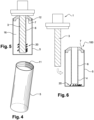
- a magnetic plug 1 comprises at one end a head or support 2 and a permanent magnet formed by a magnetic bar 3 immersed in the liquid circuit, said bar 3 attracting the metal particles 20 during the circulation of the liquid.
- the operators on site must then periodically check during maintenance operations on the ground for the presence of particles on these magnetic plugs, take the particles trapped on the magnetic bar and have them analyzed, for example by analyzes of the scanning electron microscopy type SEM and EDS spectroscopy (“energy dispersive spectroscopy”). From these analyses, it is possible to identify the nature and geometry of the particles sampled. Depending on the position of the plug in the circuit, it is then possible to circumscribe the element or elements affected by wear and take the measures which will guarantee the integrity of the machine and the safety of the flight. Various techniques are known which allow operators to remove the particles trapped on the magnetic plug.
- a first technique consists in using an adhesive tape which the operator puts in contact with the magnetic bar of the stopper. Such a solution is not entirely satisfactory insofar as the particles remain stuck to the adhesive and are difficult to separate (by dissolving the adhesive tape) for analysis. There therefore remains a residue of particles that cannot be used for analysis, which leads to a loss of information.
- the adhesive may generate surface pollution of particles which may distort the results of the material analysis.
- a second technique consists of using a cloth to pick up the particles on the magnetic bar.
- Such a solution also poses certain difficulties. Indeed, it is necessary to clean the cloth by immersing it in a solvent and then to filter the product obtained to recover the particles. Furthermore, the use of a cloth makes it difficult to recover all of the particles; therefore, all the particles is no longer available to carry out the analysis and a residue of particles remains present on the magnetic bar, this residue being liable to distort the indication of pollution during a subsequent check. Finally, the use of a potentially polluted cloth may lead to a suspicion of parasitic pollution.
- a third technique may consist in directly picking up the particles on the bar using a magnet more powerful than the magnet of the magnetic bar. Such a solution is however difficult to use because it would entail a risk of alteration of the magnetic plug by modification of the remanent field of the latter.
- the present invention aims to provide a device allowing a simple recovery (including in the context of in-situ recovery, for example under an aircraft wing), fast, reliable and complete of the magnetic particles trapped on a magnetic cap.
- the invention relates to a device for recovering magnetic particles according to one of the independent claims 1 or 8.
- the invention allows the operator to separate the magnetic particles from the magnetic plug, without any loss of said particles.
- the invention also makes it possible to secure the transport of the particles to the place where they will be analyzed with a minimum of handling and therefore a minimum risk of alteration or contamination of the particles.
- FIG. 1 schematically represents a cap 4 which is one of the elements of the device 100.
- the cap 4 according to the invention comprises a tube 6 having an open proximal end 15 and a closed distal end 14 .
- the tube 6 includes a connecting device 10 between the cap 4 and the magnetic bar 3 when the magnetic bar 3 is introduced into the tube 6.
- the connecting device 10 can also perform a sealing function between the cap 4 and the magnetic bar 3.
- the shape and dimensions of the tube 6 are complementary to the shape and dimensions of the magnetic bar 3 so that the tube 6 can cover the magnetic bar 3 as closely as possible.
- the tube 6 can be made of plastic, flexible or rigid, or of metal. In order not to disturb the magnetic field of the magnetic bar 3, the tube 6 must be non-magnetic.
- the tube 6 can be formed by a flexible elastic sheath coming to grip the magnetic bar 3 and ensuring the maintenance of the cap 4 on the latter. The elastic sheath must be able to withstand the environment in which the magnetic plug is immersed.
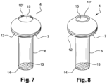
- connection and sealing device 10 between the cap 4 and the magnetic bar 3 is here formed by flexible tabs 10; this device can also be 10" rubber lugs as shown in figure 7 inserted into the tube 6 at its proximal end 15 (the other elements of the figures 7 and 8 are identical to the elements of the figure 2 ).
- the cap 4 also comprises a neck 7, of annular shape, extending towards the outside of the tube 6 and connected to the proximal end 15 of the tube 6 and supporting means 12 for reversible connection with the extractor 5 as shown in figure 4 and to which we will return later.
- the device for connecting tube 6 with bar 3 can be a ferromagnetic element 13 placed at the distal end 14 of tube 6 which, once tube 6 is in contact with magnetic bar 3, is attracted by said magnetic bar 3 and allows the maintenance between the tube 6 and the magnetic bar 3.
- This ferromagnetic element 13 can complete to the connecting device 10 between the tube 6 and the magnetic bar 3 as described above, but does not ensure the sealing function between the tube 6 and the magnetic bar 3.
- the extractor 5 shown in figure 4 is a tube comprising a proximal end and a closed distal end and which caps the tube 6 and the neck 7 so as to form a closed extraction enclosure 16 as shown in figure 5 .
- the extractor 5 can be made of plastic or metal but must be non-magnetic.
- the extractor 5 can comprise a marking zone in order to facilitate its identification.
- the reversible connection means 12 between the extractor 5 and the cap 4 are for example formed by a thread 12 on the outer diameter of the neck 7 and a thread 11 located on the extractor 5, which, by cooperating, form a system screw nut.
- Other connecting devices, not shown, can be used: by interlocking, by clipping, by lugs, etc.
- the connection between the extractor 5 and the cap 4 must be strong enough to allow the extraction of the device 100 from the bar magnetic 3 and ensure that the particles contained in the closed extraction chamber 16 do not escape.
- the magnetic cap 1 after having been extracted from the motor by the operator, is capped by the cap 4 to give the assembly illustrated in picture 3 . More precisely, the cap 4 is placed on the magnetic bar 3 until the end proximal 15 of tube 6 is in contact with head 2 of magnetic plug 1.
- the cap 1 and the cap 4 are inserted into the motor and the latter is put into operation.
- the ferromagnetic particles 20 suspended in the liquid are attracted by the magnetic bar 3 and stick to the wall of the tube 6.
- the magnetic plug is removed from the engine by the operator.
- the next step will consist in fixing the extractor 5 by screwing onto the cap 4 (via the threads 11 and 12) in order to trap the particles 20 in the extraction enclosure 16.
- the operator removes the device 100 containing the particles from the magnetic plug 1 so that the particles 20 fall to the bottom of the extractor 5 since they are no longer retained by the magnetic bar 3.
- the device 100 can then be shipped for that the analysis of the particles is carried out.
- the invention makes it possible to avoid handling the particles and therefore their possible loss or contamination. Furthermore, the device 100 is reusable once the particles have been analyzed.
- the device according to the invention which has just been described finds a particularly advantageous application in use with magnetic plugs used on all machines for which it is important to be able to detect wear, in particular on aeronautical turbomachines.
- the use of several magnetic plugs, on the various oil circuits, can make it possible to quickly locate a part showing the start of wear.
Landscapes
- Sampling And Sample Adjustment (AREA)
- Investigating Or Analyzing Materials By The Use Of Magnetic Means (AREA)
- Testing Of Engines (AREA)
- Vaporization, Distillation, Condensation, Sublimation, And Cold Traps (AREA)
- Apparatus Associated With Microorganisms And Enzymes (AREA)
Claims (10)
- Auffangvorrichtung (100) für magnetische Partikel (20), die auf einem magnetischen Stopfen (1) festgehalten sind, wobei der genannte magnetische Stopfen (1) einen magnetischen Stab (3) umfasst, der zum Zurückhalten der magnetischen Partikel (20) bestimmt ist, die durch eine Flüssigkeit mitgenommen sind, in die der magnetische Stopfen (1) eingetaucht ist, wobei die genannte Vorrichtung (100) Folgendes umfasst:- einen Aufsatz (4), der eine nicht magnetische Röhre (6) umfasst, die Folgendes umfasst:∘ ein proximales Ende (15), das mit einer Öffnung versehen ist, die geeignet ist, das Einführen des magnetischen Stabes (3) in die genannte Röhre (6) zu gewährleisten;∘ ein geschlossenes distales Ende (14), wobei die genannte Röhre (6) geeignet ist, den magnetischen Stab (3) abzudecken, wenn der magnetische Stab (3) in die genannte Röhre (6) eingeführt ist;- Mittel, die geeignet sind, den Halt zwischen dem genannten Aufsatz (4) und der magnetischen Stange (3) zu gewährleisten, wenn die magnetische Stange (3) in die genannte Röhre (6) eingeführt ist, und die biegsame Zungen (10) umfassen, die in den Aufsatz eingefügt sind und die magnetische Stange (3) durch Elastizität einklemmen;- Extraktionsmittel (5), die mit einer Öffnung versehen sind, die geeignet ist, das Einführen der genannten Röhre (6) in die genannten Extraktionsmittel (5) zu gewährleisten, wobei die genannten Extraktionsmittel (5) geeignet sind, die genannte Röhre (6) abzudecken, wenn die genannte Röhre (6) in die genannten Extraktionsmittel (5) eingeführt ist, so dass eine geschlossene Extraktionseinfassung (16) entsteht, und die in der genannten Röhre (6) festgehaltenen Partikel (20) zu empfangen, wenn der magnetische Stab (3) aus der genannten Röhre (6) herausgezogen wird, wobei die genannte Vorrichtung geeignet ist, zwecks Analyse der Partikel versandt zu werden;- Mittel, die geeignet sind, den Halt zwischen den genannten Extraktionsmitteln (5) und der genannten Röhre (6) zu gewährleisten, wenn die genannte Röhre (6) in die genannten Extraktionsmittel (5) eingeführt ist.
- Vorrichtung (100) gemäß Anspruch 1, dadurch gekennzeichnet, dass die genannten Mittel, die geeignet sind, den Halt zwischen den genannten Extraktionsmitteln (5) und der genannten Röhre (6) zu gewährleisten, wenn die genannte Röhre (6) in die genannte Einfassung (5) eingeführt ist, Mittel zur reversiblen Verbindung sind.
- Vorrichtung (100) gemäß Anspruch 2, dadurch gekennzeichnet, dass die Mittel zur reversiblen Verbindung durch ein Schrauben-Muttern-System gebildet sind, das an dem genannten proximalen Ende (15) der genannten Röhre (6) platziert ist.
- Vorrichtung (100) gemäß einem der Ansprüche 1 bis 3, dadurch gekennzeichnet, dass der genannte Aufsatz (4) einen Hals (7) umfasst, der mit dem proximalen Ende (15) der genannten Röhre verbunden und auf seinem Außendurchmesser mit einem Gewinde versehen ist.
- Vorrichtung gemäß einem der vorhergehenden Ansprüche, dadurch gekennzeichnet, dass die genannte Röhre (6) eine elastische Ummantelung ist, die geeignet ist, den magnetischen Stab (3) einzufassen.
- Vorrichtung (100) gemäß einem der vorhergehenden Ansprüche, dadurch gekennzeichnet, dass die genannte Röhre (6) ein ferromagnetisches Element (13) umfasst, das an ihrem distalen Ende (14) platziert ist.
- Vorrichtung (100) gemäß einem der vorhergehenden Ansprüche, dadurch gekennzeichnet, dass die genannten Mittel, die geeignet sind, den Halt zwischen dem genannten Aufsatz (4) und der magnetischen Stange (3) zu gewährleisten, wenn die magnetische Stange (3) in die genannte Röhre (6) eingeführt ist, Abdichtmittel umfassen, die geeignet sind, das Einfügen von metallischen Partikeln zwischen der Röhre (6) und dem magnetischen Stab (3) zu verhindern.
- Auffangvorrichtung (100) für magnetische Partikel (20), die auf einem magnetischen Stopfen (1) festgehalten sind, wobei der genannte magnetische Stopfen (1) einen magnetischen Stab (3) umfasst, der zum Zurückhalten der magnetischen Partikel (20) bestimmt ist, die durch eine Flüssigkeit mitgenommen sind, in die der magnetische Stopfen (1) eingetaucht ist, wobei die genannte Vorrichtung (100) Folgendes umfasst:- einen Aufsatz (4), der eine nicht magnetische Röhre (6) umfasst, die Folgendes umfasst:∘ ein proximales Ende (15), das mit einer Öffnung versehen ist, die geeignet ist, das Einführen des magnetischen Stabes (3) in die genannte Röhre (6) zu gewährleisten;∘ ein geschlossenes distales Ende (14), wobei die genannte Röhre (6) geeignet ist, den magnetischen Stab (3) abzudecken, wenn der magnetische Stab (3) in die genannte Röhre (6) eingeführt ist;- Mittel, die geeignet sind, den Halt zwischen dem genannten Aufsatz (4) und der magnetischen Stange (3) zu gewährleisten, wenn die magnetische Stange (3) in die genannte Röhre (6) eingeführt ist, wobei die genannten Mittel biegsame Vorsprünge umfassen, die in den Aufsatz eingefügt sind und die magnetische Stange (3) durch Elastizität einklemmen;- Extraktionsmittel (5), die mit einer Öffnung versehen sind, die geeignet ist, das Einführen der genannten Röhre (6) in die genannten Extraktionsmittel (5) zu gewährleisten, wobei die genannten Extraktionsmittel (5) geeignet sind, die genannte Röhre (6) abzudecken, wenn die genannte Röhre (6) in die genannten Extraktionsmittel (5) eingeführt ist, so dass eine geschlossene Extraktionseinfassung (16) entsteht, und die in der genannten Röhre (6) festgehaltenen Partikel (20) zu empfangen, wenn der magnetische Stab (3) aus der genannten Röhre (6) herausgezogen wird, wobei die genannte Vorrichtung geeignet ist, zwecks Analyse der Partikel versandt zu werden;- Mittel, die geeignet sind, den Halt zwischen den genannten Extraktionsmitteln (5) und der genannten Röhre (6) zu gewährleisten, wenn die genannte Röhre (6) in die genannten Extraktionsmittel (5) eingeführt ist.
- Vorrichtung (100) gemäß einem der vorhergehenden Ansprüche, wobei der genannte magnetische Stopfen (1) ein Trägerende (2) umfasst, dadurch gekennzeichnet, dass das genannte proximale Ende (15) geeignet ist, mit dem Trägerende (2) in Kontakt zu kommen, wenn der magnetische Stab (3) in die genannte Röhre (6) eingeführt ist.
- Verfahren zum Auffangen von magnetischen Partikeln, die auf einem magnetischen Stopfen festgehalten sind, mittels einer Vorrichtung gemäß einem der vorhergehenden Ansprüche, wobei das genannte Verfahren die folgenden Schritte umfasst:- Einsetzen des Aufsatzes (4) auf dem magnetischen Stab (3) des magnetische Stopfens (1) per Einführen des magnetischen Stabes (3) in die Röhre (6);- Einfügen des magnetischen Stopfens (1), der mit dem Aufsatz (4) ausgerüstet ist, in einen Motor und Betrieb des Motors;- Extraktion des magnetischen Stopfens (1) aus dem Motor;- Befestigung der Extraktionsmittel (5) auf dem Aufsatz (4);- Extraktion der Vorrichtung (100) per Entnahme des magnetischen Stabes (3) aus der Röhre (6).
Applications Claiming Priority (2)
| Application Number | Priority Date | Filing Date | Title |
|---|---|---|---|
| FR1052291A FR2957823B1 (fr) | 2010-03-29 | 2010-03-29 | Dispositif et procede de recuperation de particules magnetiques piegees sur un bouchon magnetique |
| PCT/FR2011/050577 WO2011121207A1 (fr) | 2010-03-29 | 2011-03-21 | Dispositif et procede de recuperation de particules magnetiques piegees sur un bouchon magnetique |
Publications (3)
| Publication Number | Publication Date |
|---|---|
| EP2552590A1 EP2552590A1 (de) | 2013-02-06 |
| EP2552590B1 EP2552590B1 (de) | 2019-05-22 |
| EP2552590B2 true EP2552590B2 (de) | 2023-02-22 |
Family
ID=42731965
Family Applications (1)
| Application Number | Title | Priority Date | Filing Date |
|---|---|---|---|
| EP11715956.6A Active EP2552590B2 (de) | 2010-03-29 | 2011-03-21 | Verfahren und vorrichtung zur rückgewinnung von auf einem magnetstopfen gefangenen magnetischen partikeln |
Country Status (10)
| Country | Link |
|---|---|
| US (1) | US9687857B2 (de) |
| EP (1) | EP2552590B2 (de) |
| JP (1) | JP5830521B2 (de) |
| CN (1) | CN102821865B (de) |
| BR (1) | BR112012024507B1 (de) |
| CA (1) | CA2793984C (de) |
| ES (1) | ES2730934T5 (de) |
| FR (1) | FR2957823B1 (de) |
| RU (1) | RU2553721C2 (de) |
| WO (1) | WO2011121207A1 (de) |
Families Citing this family (6)
| Publication number | Priority date | Publication date | Assignee | Title |
|---|---|---|---|---|
| JP5454825B1 (ja) * | 2013-09-18 | 2014-03-26 | 株式会社ヤリステ | 磁気粉分離装置 |
| JP6380034B2 (ja) * | 2014-11-17 | 2018-08-29 | 株式会社豊田自動織機 | 車載用電子機器 |
| JP6680742B2 (ja) * | 2017-10-31 | 2020-04-15 | 大研医器株式会社 | 磁性粒子収集方法及び試験セット |
| CN110479482B (zh) * | 2019-07-19 | 2024-08-06 | 惠州锂威新能源科技有限公司 | 一种可快速清洁的吸附装置及其装配方法 |
| KR102348813B1 (ko) * | 2021-02-24 | 2022-01-10 | 문경희 | 강성 강화 자석봉 |
| CN114534911B (zh) * | 2022-02-25 | 2024-04-09 | 奥星制药设备(石家庄)有限公司 | 一种磁性分离器及清洗方法 |
Citations (12)
| Publication number | Priority date | Publication date | Assignee | Title |
|---|---|---|---|---|
| US2594955A (en) † | 1950-08-22 | 1952-04-29 | Albert A Markowitz | Magnetic holder for pencils |
| US2975667A (en) † | 1957-07-22 | 1961-03-21 | Camloc Fastener Corp | Retaining ring for rotary stud fastener |
| US3068316A (en) † | 1959-06-12 | 1962-12-11 | Witt Governor | Cord shortening holder |
| US4644610A (en) † | 1984-09-06 | 1987-02-24 | Fish Ivan L | Disc shaped holder with an expandable center hole |
| GB2232098A (en) † | 1989-05-04 | 1990-12-05 | Univ Swansea | Magnetic removal of debris |
| US5043063A (en) † | 1990-03-21 | 1991-08-27 | Eriez Manufacturing Company | Magnetic trap and cleaning means therefor |
| US5619569A (en) † | 1995-05-19 | 1997-04-08 | Mcvay; Clifford R. | Coil cord snarl preventing device and method |
| US5906303A (en) † | 1997-04-03 | 1999-05-25 | Carone; Nicholas J. | Baton holder |
| USD425740S (en) † | 1997-11-20 | 2000-05-30 | Daly Michael W | Paper roll brake |
| US6173851B1 (en) † | 1999-03-18 | 2001-01-16 | Anesta Corporation | Method and apparatus for the interim storage of medicated oral dosage forms |
| USD445980S1 (en) † | 2000-06-20 | 2001-07-31 | Sockpro, Inc. | Sock holder |
| US20070262028A1 (en) † | 2006-05-12 | 2007-11-15 | The Lee Company | Method and device for magnetically filtering fluids |
Family Cites Families (16)
| Publication number | Priority date | Publication date | Assignee | Title |
|---|---|---|---|---|
| US2693979A (en) * | 1950-08-03 | 1954-11-09 | George L Russell | Magnetic device |
| GB855928A (en) * | 1957-08-02 | 1960-12-14 | Thoma Jean Ulrich | Magnetic separators |
| SE8601143L (sv) * | 1986-03-12 | 1987-09-13 | Carbematrix Ab | Sett och anordning for samling och spridning av ferromagnetiska partiklar i ett fluidformigt medium |
| US5027966A (en) * | 1989-09-12 | 1991-07-02 | Yadock David J | Storage containers with magnetic handling means |
| JPH066896U (ja) * | 1992-06-26 | 1994-01-28 | 株式会社トーキン | ドレンボルト |
| FI944937A0 (fi) * | 1994-10-20 | 1994-10-20 | Labsystems Oy | Separeringsanordning |
| JPH0938522A (ja) * | 1995-07-25 | 1997-02-10 | Somic Ishikawa:Kk | 鉄粉吸着装置 |
| US5949317A (en) * | 1998-03-31 | 1999-09-07 | Fink; Randy | Magnetic drain plug |
| FI20000583A0 (fi) * | 2000-03-14 | 2000-03-14 | Labsystems Oy | Astia ja sauva |
| US20020088756A1 (en) * | 2001-01-05 | 2002-07-11 | Wolosion Dan L. | Magnetic cleaning tool |
| US6730217B2 (en) * | 2002-03-29 | 2004-05-04 | Insul-Magnetics, Inc. | Magnetic particle separator and method |
| CN100538362C (zh) * | 2002-11-07 | 2009-09-09 | 株式会社三菱化学药得论 | 用于收集磁性颗粒的磁性材料及其应用 |
| FR2848128B1 (fr) * | 2002-12-10 | 2005-09-02 | Progalva Net Et 9 | Dispositif de desembouage magnetique |
| JP2004195341A (ja) * | 2002-12-17 | 2004-07-15 | Aichi Steel Works Ltd | 磁性体粉吸着装置及び磁性体粉吸着装置用磁石 |
| CN201172006Y (zh) * | 2008-01-10 | 2008-12-31 | 东南大学 | 燃煤可吸入颗粒物的捕集装置 |
| FR2951961B1 (fr) * | 2009-10-30 | 2011-11-04 | Snecma | Dispositif et procede de recuperation de particules magnetiques piegees sur un bouchon magnetique |
-
2010
- 2010-03-29 FR FR1052291A patent/FR2957823B1/fr active Active
-
2011
- 2011-03-21 EP EP11715956.6A patent/EP2552590B2/de active Active
- 2011-03-21 JP JP2013501893A patent/JP5830521B2/ja active Active
- 2011-03-21 RU RU2012145457/03A patent/RU2553721C2/ru active
- 2011-03-21 ES ES11715956T patent/ES2730934T5/es active Active
- 2011-03-21 CN CN201180017762.7A patent/CN102821865B/zh active Active
- 2011-03-21 WO PCT/FR2011/050577 patent/WO2011121207A1/fr not_active Ceased
- 2011-03-21 BR BR112012024507-4A patent/BR112012024507B1/pt active IP Right Grant
- 2011-03-21 US US13/637,160 patent/US9687857B2/en active Active
- 2011-03-21 CA CA2793984A patent/CA2793984C/fr active Active
Patent Citations (12)
| Publication number | Priority date | Publication date | Assignee | Title |
|---|---|---|---|---|
| US2594955A (en) † | 1950-08-22 | 1952-04-29 | Albert A Markowitz | Magnetic holder for pencils |
| US2975667A (en) † | 1957-07-22 | 1961-03-21 | Camloc Fastener Corp | Retaining ring for rotary stud fastener |
| US3068316A (en) † | 1959-06-12 | 1962-12-11 | Witt Governor | Cord shortening holder |
| US4644610A (en) † | 1984-09-06 | 1987-02-24 | Fish Ivan L | Disc shaped holder with an expandable center hole |
| GB2232098A (en) † | 1989-05-04 | 1990-12-05 | Univ Swansea | Magnetic removal of debris |
| US5043063A (en) † | 1990-03-21 | 1991-08-27 | Eriez Manufacturing Company | Magnetic trap and cleaning means therefor |
| US5619569A (en) † | 1995-05-19 | 1997-04-08 | Mcvay; Clifford R. | Coil cord snarl preventing device and method |
| US5906303A (en) † | 1997-04-03 | 1999-05-25 | Carone; Nicholas J. | Baton holder |
| USD425740S (en) † | 1997-11-20 | 2000-05-30 | Daly Michael W | Paper roll brake |
| US6173851B1 (en) † | 1999-03-18 | 2001-01-16 | Anesta Corporation | Method and apparatus for the interim storage of medicated oral dosage forms |
| USD445980S1 (en) † | 2000-06-20 | 2001-07-31 | Sockpro, Inc. | Sock holder |
| US20070262028A1 (en) † | 2006-05-12 | 2007-11-15 | The Lee Company | Method and device for magnetically filtering fluids |
Also Published As
| Publication number | Publication date |
|---|---|
| FR2957823B1 (fr) | 2015-02-27 |
| US20130037470A1 (en) | 2013-02-14 |
| BR112012024507B1 (pt) | 2021-01-12 |
| EP2552590B1 (de) | 2019-05-22 |
| CA2793984C (fr) | 2018-05-29 |
| CN102821865A (zh) | 2012-12-12 |
| JP2013523430A (ja) | 2013-06-17 |
| CN102821865B (zh) | 2015-07-22 |
| FR2957823A1 (fr) | 2011-09-30 |
| US9687857B2 (en) | 2017-06-27 |
| WO2011121207A1 (fr) | 2011-10-06 |
| CA2793984A1 (fr) | 2011-10-06 |
| EP2552590A1 (de) | 2013-02-06 |
| ES2730934T5 (es) | 2023-04-26 |
| JP5830521B2 (ja) | 2015-12-09 |
| ES2730934T3 (es) | 2019-11-13 |
| RU2012145457A (ru) | 2014-05-10 |
| BR112012024507A2 (pt) | 2016-09-06 |
| RU2553721C2 (ru) | 2015-06-20 |
Similar Documents
| Publication | Publication Date | Title |
|---|---|---|
| EP2552590B2 (de) | Verfahren und vorrichtung zur rückgewinnung von auf einem magnetstopfen gefangenen magnetischen partikeln | |
| CA2778856C (fr) | Dispositif et procede de recuperation de particules magnetiques piegees sur un bouchon magnetique | |
| FR3004379A1 (fr) | Procede de fabrication d'un bouchon de fermeture du goulot d'un contenant, procede de bouchage d'un contenant par un bouchon fabrique selon un tel procede et bouchon fabrique selon un tel procede | |
| EP3043916B1 (de) | Elektrostatischer kollektor | |
| EP0190519B1 (de) | Verfahren und Vorrichtung zur Ausziehung von optischen Fasern | |
| FR3059908A1 (fr) | Dispositif de capuchonnage et de retrait d'aiguille d'injection destine a une seringue, notamment une seringue a cartouche dentaire | |
| US20120140372A1 (en) | Device for electrically discharging samples of an electrically nonconductive liquid | |
| EP0540409B1 (de) | Vorrichtung zum Montieren eines Beutels auf einem Rohrstutzen eines Handschuhkastens | |
| WO2024133799A1 (fr) | Dispositif de distribution de composants d'assemblage equipe d'au moins un extracteur de composants comprenant plusieurs parties mobiles entre elles. | |
| WO2004097375A2 (fr) | Procede et dispositif de soutirage de liquide et en particulier d’huile de transformateur | |
| FR2808226A1 (fr) | Procede de nettoyage de bougies magnetiques et dispositif mis en oeuvre dans ce procede | |
| FR2691080A1 (fr) | Séparateur magnétique à supraconduction notamment pour retraitement d'un combustible nucléaire et procédé de mise en Óoeuvre. | |
| US20100039744A1 (en) | Device for electrically discharging samples of an electrically non conductive liquid | |
| FR3014720A1 (fr) | Outil de retrait d'un opercule. | |
| FR2994379A1 (fr) | Dispositif de recuperation de prelevement | |
| FR3001165A1 (fr) | Crayon a souder permettant le chargement automatique de billes |
Legal Events
| Date | Code | Title | Description |
|---|---|---|---|
| PUAI | Public reference made under article 153(3) epc to a published international application that has entered the european phase |
Free format text: ORIGINAL CODE: 0009012 |
|
| 17P | Request for examination filed |
Effective date: 20121026 |
|
| AK | Designated contracting states |
Kind code of ref document: A1 Designated state(s): AL AT BE BG CH CY CZ DE DK EE ES FI FR GB GR HR HU IE IS IT LI LT LU LV MC MK MT NL NO PL PT RO RS SE SI SK SM TR |
|
| DAX | Request for extension of the european patent (deleted) | ||
| 17Q | First examination report despatched |
Effective date: 20160113 |
|
| RAP1 | Party data changed (applicant data changed or rights of an application transferred) |
Owner name: SAFRAN AIRCRAFT ENGINES |
|
| GRAP | Despatch of communication of intention to grant a patent |
Free format text: ORIGINAL CODE: EPIDOSNIGR1 |
|
| STAA | Information on the status of an ep patent application or granted ep patent |
Free format text: STATUS: GRANT OF PATENT IS INTENDED |
|
| INTG | Intention to grant announced |
Effective date: 20190118 |
|
| GRAS | Grant fee paid |
Free format text: ORIGINAL CODE: EPIDOSNIGR3 |
|
| GRAA | (expected) grant |
Free format text: ORIGINAL CODE: 0009210 |
|
| STAA | Information on the status of an ep patent application or granted ep patent |
Free format text: STATUS: THE PATENT HAS BEEN GRANTED |
|
| AK | Designated contracting states |
Kind code of ref document: B1 Designated state(s): AL AT BE BG CH CY CZ DE DK EE ES FI FR GB GR HR HU IE IS IT LI LT LU LV MC MK MT NL NO PL PT RO RS SE SI SK SM TR |
|
| REG | Reference to a national code |
Ref country code: GB Ref legal event code: FG4D Free format text: NOT ENGLISH |
|
| REG | Reference to a national code |
Ref country code: CH Ref legal event code: EP |
|
| REG | Reference to a national code |
Ref country code: IE Ref legal event code: FG4D Free format text: LANGUAGE OF EP DOCUMENT: FRENCH |
|
| REG | Reference to a national code |
Ref country code: DE Ref legal event code: R096 Ref document number: 602011059164 Country of ref document: DE |
|
| REG | Reference to a national code |
Ref country code: AT Ref legal event code: REF Ref document number: 1135451 Country of ref document: AT Kind code of ref document: T Effective date: 20190615 |
|
| REG | Reference to a national code |
Ref country code: SE Ref legal event code: TRGR |
|
| REG | Reference to a national code |
Ref country code: NL Ref legal event code: MP Effective date: 20190522 |
|
| REG | Reference to a national code |
Ref country code: LT Ref legal event code: MG4D |
|
| PG25 | Lapsed in a contracting state [announced via postgrant information from national office to epo] |
Ref country code: AL Free format text: LAPSE BECAUSE OF FAILURE TO SUBMIT A TRANSLATION OF THE DESCRIPTION OR TO PAY THE FEE WITHIN THE PRESCRIBED TIME-LIMIT Effective date: 20190522 Ref country code: PT Free format text: LAPSE BECAUSE OF FAILURE TO SUBMIT A TRANSLATION OF THE DESCRIPTION OR TO PAY THE FEE WITHIN THE PRESCRIBED TIME-LIMIT Effective date: 20190922 Ref country code: NL Free format text: LAPSE BECAUSE OF FAILURE TO SUBMIT A TRANSLATION OF THE DESCRIPTION OR TO PAY THE FEE WITHIN THE PRESCRIBED TIME-LIMIT Effective date: 20190522 Ref country code: NO Free format text: LAPSE BECAUSE OF FAILURE TO SUBMIT A TRANSLATION OF THE DESCRIPTION OR TO PAY THE FEE WITHIN THE PRESCRIBED TIME-LIMIT Effective date: 20190822 Ref country code: LT Free format text: LAPSE BECAUSE OF FAILURE TO SUBMIT A TRANSLATION OF THE DESCRIPTION OR TO PAY THE FEE WITHIN THE PRESCRIBED TIME-LIMIT Effective date: 20190522 Ref country code: FI Free format text: LAPSE BECAUSE OF FAILURE TO SUBMIT A TRANSLATION OF THE DESCRIPTION OR TO PAY THE FEE WITHIN THE PRESCRIBED TIME-LIMIT Effective date: 20190522 Ref country code: HR Free format text: LAPSE BECAUSE OF FAILURE TO SUBMIT A TRANSLATION OF THE DESCRIPTION OR TO PAY THE FEE WITHIN THE PRESCRIBED TIME-LIMIT Effective date: 20190522 |
|
| REG | Reference to a national code |
Ref country code: ES Ref legal event code: FG2A Ref document number: 2730934 Country of ref document: ES Kind code of ref document: T3 Effective date: 20191113 |
|
| PG25 | Lapsed in a contracting state [announced via postgrant information from national office to epo] |
Ref country code: RS Free format text: LAPSE BECAUSE OF FAILURE TO SUBMIT A TRANSLATION OF THE DESCRIPTION OR TO PAY THE FEE WITHIN THE PRESCRIBED TIME-LIMIT Effective date: 20190522 Ref country code: LV Free format text: LAPSE BECAUSE OF FAILURE TO SUBMIT A TRANSLATION OF THE DESCRIPTION OR TO PAY THE FEE WITHIN THE PRESCRIBED TIME-LIMIT Effective date: 20190522 Ref country code: GR Free format text: LAPSE BECAUSE OF FAILURE TO SUBMIT A TRANSLATION OF THE DESCRIPTION OR TO PAY THE FEE WITHIN THE PRESCRIBED TIME-LIMIT Effective date: 20190823 Ref country code: BG Free format text: LAPSE BECAUSE OF FAILURE TO SUBMIT A TRANSLATION OF THE DESCRIPTION OR TO PAY THE FEE WITHIN THE PRESCRIBED TIME-LIMIT Effective date: 20190822 |
|
| REG | Reference to a national code |
Ref country code: AT Ref legal event code: MK05 Ref document number: 1135451 Country of ref document: AT Kind code of ref document: T Effective date: 20190522 |
|
| PG25 | Lapsed in a contracting state [announced via postgrant information from national office to epo] |
Ref country code: DK Free format text: LAPSE BECAUSE OF FAILURE TO SUBMIT A TRANSLATION OF THE DESCRIPTION OR TO PAY THE FEE WITHIN THE PRESCRIBED TIME-LIMIT Effective date: 20190522 Ref country code: AT Free format text: LAPSE BECAUSE OF FAILURE TO SUBMIT A TRANSLATION OF THE DESCRIPTION OR TO PAY THE FEE WITHIN THE PRESCRIBED TIME-LIMIT Effective date: 20190522 Ref country code: EE Free format text: LAPSE BECAUSE OF FAILURE TO SUBMIT A TRANSLATION OF THE DESCRIPTION OR TO PAY THE FEE WITHIN THE PRESCRIBED TIME-LIMIT Effective date: 20190522 Ref country code: CZ Free format text: LAPSE BECAUSE OF FAILURE TO SUBMIT A TRANSLATION OF THE DESCRIPTION OR TO PAY THE FEE WITHIN THE PRESCRIBED TIME-LIMIT Effective date: 20190522 Ref country code: RO Free format text: LAPSE BECAUSE OF FAILURE TO SUBMIT A TRANSLATION OF THE DESCRIPTION OR TO PAY THE FEE WITHIN THE PRESCRIBED TIME-LIMIT Effective date: 20190522 Ref country code: SK Free format text: LAPSE BECAUSE OF FAILURE TO SUBMIT A TRANSLATION OF THE DESCRIPTION OR TO PAY THE FEE WITHIN THE PRESCRIBED TIME-LIMIT Effective date: 20190522 |
|
| REG | Reference to a national code |
Ref country code: DE Ref legal event code: R026 Ref document number: 602011059164 Country of ref document: DE |
|
| PG25 | Lapsed in a contracting state [announced via postgrant information from national office to epo] |
Ref country code: SM Free format text: LAPSE BECAUSE OF FAILURE TO SUBMIT A TRANSLATION OF THE DESCRIPTION OR TO PAY THE FEE WITHIN THE PRESCRIBED TIME-LIMIT Effective date: 20190522 |
|
| PLBI | Opposition filed |
Free format text: ORIGINAL CODE: 0009260 |
|
| PLAX | Notice of opposition and request to file observation + time limit sent |
Free format text: ORIGINAL CODE: EPIDOSNOBS2 |
|
| PG25 | Lapsed in a contracting state [announced via postgrant information from national office to epo] |
Ref country code: TR Free format text: LAPSE BECAUSE OF FAILURE TO SUBMIT A TRANSLATION OF THE DESCRIPTION OR TO PAY THE FEE WITHIN THE PRESCRIBED TIME-LIMIT Effective date: 20190522 |
|
| 26 | Opposition filed |
Opponent name: UNITED TECHNOLOGIES CORPORATION Effective date: 20200221 |
|
| PG25 | Lapsed in a contracting state [announced via postgrant information from national office to epo] |
Ref country code: PL Free format text: LAPSE BECAUSE OF FAILURE TO SUBMIT A TRANSLATION OF THE DESCRIPTION OR TO PAY THE FEE WITHIN THE PRESCRIBED TIME-LIMIT Effective date: 20190522 |
|
| PG25 | Lapsed in a contracting state [announced via postgrant information from national office to epo] |
Ref country code: SI Free format text: LAPSE BECAUSE OF FAILURE TO SUBMIT A TRANSLATION OF THE DESCRIPTION OR TO PAY THE FEE WITHIN THE PRESCRIBED TIME-LIMIT Effective date: 20190522 |
|
| PLAF | Information modified related to communication of a notice of opposition and request to file observations + time limit |
Free format text: ORIGINAL CODE: EPIDOSCOBS2 |
|
| PLAB | Opposition data, opponent's data or that of the opponent's representative modified |
Free format text: ORIGINAL CODE: 0009299OPPO |
|
| PLBB | Reply of patent proprietor to notice(s) of opposition received |
Free format text: ORIGINAL CODE: EPIDOSNOBS3 |
|
| R26 | Opposition filed (corrected) |
Opponent name: RAYTHEON TECHNOLOGIES CORPORATION Effective date: 20200221 |
|
| PG25 | Lapsed in a contracting state [announced via postgrant information from national office to epo] |
Ref country code: MC Free format text: LAPSE BECAUSE OF FAILURE TO SUBMIT A TRANSLATION OF THE DESCRIPTION OR TO PAY THE FEE WITHIN THE PRESCRIBED TIME-LIMIT Effective date: 20190522 |
|
| REG | Reference to a national code |
Ref country code: CH Ref legal event code: PL |
|
| REG | Reference to a national code |
Ref country code: BE Ref legal event code: MM Effective date: 20200331 |
|
| PG25 | Lapsed in a contracting state [announced via postgrant information from national office to epo] |
Ref country code: LU Free format text: LAPSE BECAUSE OF NON-PAYMENT OF DUE FEES Effective date: 20200321 |
|
| PG25 | Lapsed in a contracting state [announced via postgrant information from national office to epo] |
Ref country code: CH Free format text: LAPSE BECAUSE OF NON-PAYMENT OF DUE FEES Effective date: 20200331 Ref country code: LI Free format text: LAPSE BECAUSE OF NON-PAYMENT OF DUE FEES Effective date: 20200331 Ref country code: IE Free format text: LAPSE BECAUSE OF NON-PAYMENT OF DUE FEES Effective date: 20200321 |
|
| PG25 | Lapsed in a contracting state [announced via postgrant information from national office to epo] |
Ref country code: BE Free format text: LAPSE BECAUSE OF NON-PAYMENT OF DUE FEES Effective date: 20200331 |
|
| PG25 | Lapsed in a contracting state [announced via postgrant information from national office to epo] |
Ref country code: MT Free format text: LAPSE BECAUSE OF FAILURE TO SUBMIT A TRANSLATION OF THE DESCRIPTION OR TO PAY THE FEE WITHIN THE PRESCRIBED TIME-LIMIT Effective date: 20190522 Ref country code: CY Free format text: LAPSE BECAUSE OF FAILURE TO SUBMIT A TRANSLATION OF THE DESCRIPTION OR TO PAY THE FEE WITHIN THE PRESCRIBED TIME-LIMIT Effective date: 20190522 |
|
| PG25 | Lapsed in a contracting state [announced via postgrant information from national office to epo] |
Ref country code: MK Free format text: LAPSE BECAUSE OF FAILURE TO SUBMIT A TRANSLATION OF THE DESCRIPTION OR TO PAY THE FEE WITHIN THE PRESCRIBED TIME-LIMIT Effective date: 20190522 Ref country code: IS Free format text: LAPSE BECAUSE OF FAILURE TO SUBMIT A TRANSLATION OF THE DESCRIPTION OR TO PAY THE FEE WITHIN THE PRESCRIBED TIME-LIMIT Effective date: 20190922 |
|
| APAH | Appeal reference modified |
Free format text: ORIGINAL CODE: EPIDOSCREFNO |
|
| APBM | Appeal reference recorded |
Free format text: ORIGINAL CODE: EPIDOSNREFNO |
|
| APBP | Date of receipt of notice of appeal recorded |
Free format text: ORIGINAL CODE: EPIDOSNNOA2O |
|
| APBU | Appeal procedure closed |
Free format text: ORIGINAL CODE: EPIDOSNNOA9O |
|
| PUAH | Patent maintained in amended form |
Free format text: ORIGINAL CODE: 0009272 |
|
| STAA | Information on the status of an ep patent application or granted ep patent |
Free format text: STATUS: PATENT MAINTAINED AS AMENDED |
|
| 27A | Patent maintained in amended form |
Effective date: 20230222 |
|
| AK | Designated contracting states |
Kind code of ref document: B2 Designated state(s): AL AT BE BG CH CY CZ DE DK EE ES FI FR GB GR HR HU IE IS IT LI LT LU LV MC MK MT NL NO PL PT RO RS SE SI SK SM TR |
|
| REG | Reference to a national code |
Ref country code: DE Ref legal event code: R102 Ref document number: 602011059164 Country of ref document: DE |
|
| REG | Reference to a national code |
Ref country code: SE Ref legal event code: RPEO |
|
| REG | Reference to a national code |
Ref country code: ES Ref legal event code: DC2A Ref document number: 2730934 Country of ref document: ES Kind code of ref document: T5 Effective date: 20230426 |
|
| PGFP | Annual fee paid to national office [announced via postgrant information from national office to epo] |
Ref country code: DE Payment date: 20250218 Year of fee payment: 15 |
|
| PGFP | Annual fee paid to national office [announced via postgrant information from national office to epo] |
Ref country code: SE Payment date: 20250218 Year of fee payment: 15 |
|
| PGFP | Annual fee paid to national office [announced via postgrant information from national office to epo] |
Ref country code: FR Payment date: 20250218 Year of fee payment: 15 |
|
| PGFP | Annual fee paid to national office [announced via postgrant information from national office to epo] |
Ref country code: GB Payment date: 20250221 Year of fee payment: 15 Ref country code: IT Payment date: 20250218 Year of fee payment: 15 |
|
| PGFP | Annual fee paid to national office [announced via postgrant information from national office to epo] |
Ref country code: ES Payment date: 20250401 Year of fee payment: 15 |