EP2552590B2 - Dispositif et procede de recuperation de particules magnetiques piegees sur un bouchon magnetique - Google Patents
Dispositif et procede de recuperation de particules magnetiques piegees sur un bouchon magnetique Download PDFInfo
- Publication number
- EP2552590B2 EP2552590B2 EP11715956.6A EP11715956A EP2552590B2 EP 2552590 B2 EP2552590 B2 EP 2552590B2 EP 11715956 A EP11715956 A EP 11715956A EP 2552590 B2 EP2552590 B2 EP 2552590B2
- Authority
- EP
- European Patent Office
- Prior art keywords
- tube
- bar magnet
- cap
- magnetic
- particles
- Prior art date
- Legal status (The legal status is an assumption and is not a legal conclusion. Google has not performed a legal analysis and makes no representation as to the accuracy of the status listed.)
- Active
Links
Images

Classifications
-
- B—PERFORMING OPERATIONS; TRANSPORTING
- B03—SEPARATION OF SOLID MATERIALS USING LIQUIDS OR USING PNEUMATIC TABLES OR JIGS; MAGNETIC OR ELECTROSTATIC SEPARATION OF SOLID MATERIALS FROM SOLID MATERIALS OR FLUIDS; SEPARATION BY HIGH-VOLTAGE ELECTRIC FIELDS
- B03C—MAGNETIC OR ELECTROSTATIC SEPARATION OF SOLID MATERIALS FROM SOLID MATERIALS OR FLUIDS; SEPARATION BY HIGH-VOLTAGE ELECTRIC FIELDS
- B03C1/00—Magnetic separation
- B03C1/02—Magnetic separation acting directly on the substance being separated
- B03C1/025—High gradient magnetic separators
- B03C1/031—Component parts; Auxiliary operations
- B03C1/032—Matrix cleaning systems
-
- B—PERFORMING OPERATIONS; TRANSPORTING
- B03—SEPARATION OF SOLID MATERIALS USING LIQUIDS OR USING PNEUMATIC TABLES OR JIGS; MAGNETIC OR ELECTROSTATIC SEPARATION OF SOLID MATERIALS FROM SOLID MATERIALS OR FLUIDS; SEPARATION BY HIGH-VOLTAGE ELECTRIC FIELDS
- B03C—MAGNETIC OR ELECTROSTATIC SEPARATION OF SOLID MATERIALS FROM SOLID MATERIALS OR FLUIDS; SEPARATION BY HIGH-VOLTAGE ELECTRIC FIELDS
- B03C1/00—Magnetic separation
- B03C1/02—Magnetic separation acting directly on the substance being separated
- B03C1/28—Magnetic plugs and dipsticks
- B03C1/286—Magnetic plugs and dipsticks disposed at the inner circumference of a recipient, e.g. magnetic drain bolt
-
- B—PERFORMING OPERATIONS; TRANSPORTING
- B03—SEPARATION OF SOLID MATERIALS USING LIQUIDS OR USING PNEUMATIC TABLES OR JIGS; MAGNETIC OR ELECTROSTATIC SEPARATION OF SOLID MATERIALS FROM SOLID MATERIALS OR FLUIDS; SEPARATION BY HIGH-VOLTAGE ELECTRIC FIELDS
- B03C—MAGNETIC OR ELECTROSTATIC SEPARATION OF SOLID MATERIALS FROM SOLID MATERIALS OR FLUIDS; SEPARATION BY HIGH-VOLTAGE ELECTRIC FIELDS
- B03C2201/00—Details of magnetic or electrostatic separation
- B03C2201/18—Magnetic separation whereby the particles are suspended in a liquid
-
- B—PERFORMING OPERATIONS; TRANSPORTING
- B03—SEPARATION OF SOLID MATERIALS USING LIQUIDS OR USING PNEUMATIC TABLES OR JIGS; MAGNETIC OR ELECTROSTATIC SEPARATION OF SOLID MATERIALS FROM SOLID MATERIALS OR FLUIDS; SEPARATION BY HIGH-VOLTAGE ELECTRIC FIELDS
- B03C—MAGNETIC OR ELECTROSTATIC SEPARATION OF SOLID MATERIALS FROM SOLID MATERIALS OR FLUIDS; SEPARATION BY HIGH-VOLTAGE ELECTRIC FIELDS
- B03C2201/00—Details of magnetic or electrostatic separation
- B03C2201/28—Parts being designed to be removed for cleaning purposes
Definitions
- the invention relates to a device and a method for recovering magnetic particles trapped on a magnetic plug intended to retain, by means of a magnet, the magnetic particles entrained by a liquid and resulting from the wear of parts, such as for example the rotating parts arranged in an equipment or aircraft engine casing.
- a magnetic plug is placed in a circuit of moving liquid (typically oil, coolant or fuel) inside a casing containing moving parts, such as gears. or bearings, which bathe in said liquid.
- moving liquid typically oil, coolant or fuel
- the function of the liquid circuit is to allow the lubrication and/or cooling of moving parts (typically rotating parts).
- moving parts are bound to wear during their lifetime, for example due to friction resulting from contact between two toothed wheels or bearings, or due to intense shocks or friction between rotating parts due to to intense and abnormal vibrations propagating in the crankcase.
- the wear of the parts leads to the formation of particles which detach from the parts and are carried by the liquid in the liquid circuit. Since rotating parts are generally metallic, the particles resulting from the wear of the parts are conductive and are generally in the form of filings.
- the parts are most often made of a metal of the ferromagnetic type such as iron, that is to say capable of being attracted by a magnetic element such as a magnet.
- the magnetic plug is typically used in addition to a conventional filter, placed downstream of the plug, which will filter non-magnetic particles. Filters and caps are placed so that their maintenance is facilitated.
- a magnetic plug 1 comprises at one end a head or support 2 and a permanent magnet formed by a magnetic bar 3 immersed in the liquid circuit, said bar 3 attracting the metal particles 20 during the circulation of the liquid.
- the operators on site must then periodically check during maintenance operations on the ground for the presence of particles on these magnetic plugs, take the particles trapped on the magnetic bar and have them analyzed, for example by analyzes of the scanning electron microscopy type SEM and EDS spectroscopy (“energy dispersive spectroscopy”). From these analyses, it is possible to identify the nature and geometry of the particles sampled. Depending on the position of the plug in the circuit, it is then possible to circumscribe the element or elements affected by wear and take the measures which will guarantee the integrity of the machine and the safety of the flight. Various techniques are known which allow operators to remove the particles trapped on the magnetic plug.
- a first technique consists in using an adhesive tape which the operator puts in contact with the magnetic bar of the stopper. Such a solution is not entirely satisfactory insofar as the particles remain stuck to the adhesive and are difficult to separate (by dissolving the adhesive tape) for analysis. There therefore remains a residue of particles that cannot be used for analysis, which leads to a loss of information.
- the adhesive may generate surface pollution of particles which may distort the results of the material analysis.
- a second technique consists of using a cloth to pick up the particles on the magnetic bar.
- Such a solution also poses certain difficulties. Indeed, it is necessary to clean the cloth by immersing it in a solvent and then to filter the product obtained to recover the particles. Furthermore, the use of a cloth makes it difficult to recover all of the particles; therefore, all the particles is no longer available to carry out the analysis and a residue of particles remains present on the magnetic bar, this residue being liable to distort the indication of pollution during a subsequent check. Finally, the use of a potentially polluted cloth may lead to a suspicion of parasitic pollution.
- a third technique may consist in directly picking up the particles on the bar using a magnet more powerful than the magnet of the magnetic bar. Such a solution is however difficult to use because it would entail a risk of alteration of the magnetic plug by modification of the remanent field of the latter.
- the present invention aims to provide a device allowing a simple recovery (including in the context of in-situ recovery, for example under an aircraft wing), fast, reliable and complete of the magnetic particles trapped on a magnetic cap.
- the invention relates to a device for recovering magnetic particles according to one of the independent claims 1 or 8.
- the invention allows the operator to separate the magnetic particles from the magnetic plug, without any loss of said particles.
- the invention also makes it possible to secure the transport of the particles to the place where they will be analyzed with a minimum of handling and therefore a minimum risk of alteration or contamination of the particles.
- FIG. 1 schematically represents a cap 4 which is one of the elements of the device 100.
- the cap 4 according to the invention comprises a tube 6 having an open proximal end 15 and a closed distal end 14 .
- the tube 6 includes a connecting device 10 between the cap 4 and the magnetic bar 3 when the magnetic bar 3 is introduced into the tube 6.
- the connecting device 10 can also perform a sealing function between the cap 4 and the magnetic bar 3.
- the shape and dimensions of the tube 6 are complementary to the shape and dimensions of the magnetic bar 3 so that the tube 6 can cover the magnetic bar 3 as closely as possible.
- the tube 6 can be made of plastic, flexible or rigid, or of metal. In order not to disturb the magnetic field of the magnetic bar 3, the tube 6 must be non-magnetic.
- the tube 6 can be formed by a flexible elastic sheath coming to grip the magnetic bar 3 and ensuring the maintenance of the cap 4 on the latter. The elastic sheath must be able to withstand the environment in which the magnetic plug is immersed.
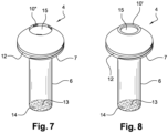
- connection and sealing device 10 between the cap 4 and the magnetic bar 3 is here formed by flexible tabs 10; this device can also be 10" rubber lugs as shown in figure 7 inserted into the tube 6 at its proximal end 15 (the other elements of the figures 7 and 8 are identical to the elements of the figure 2 ).
- the cap 4 also comprises a neck 7, of annular shape, extending towards the outside of the tube 6 and connected to the proximal end 15 of the tube 6 and supporting means 12 for reversible connection with the extractor 5 as shown in figure 4 and to which we will return later.
- the device for connecting tube 6 with bar 3 can be a ferromagnetic element 13 placed at the distal end 14 of tube 6 which, once tube 6 is in contact with magnetic bar 3, is attracted by said magnetic bar 3 and allows the maintenance between the tube 6 and the magnetic bar 3.
- This ferromagnetic element 13 can complete to the connecting device 10 between the tube 6 and the magnetic bar 3 as described above, but does not ensure the sealing function between the tube 6 and the magnetic bar 3.
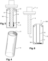
- the extractor 5 shown in figure 4 is a tube comprising a proximal end and a closed distal end and which caps the tube 6 and the neck 7 so as to form a closed extraction enclosure 16 as shown in figure 5 .
- the extractor 5 can be made of plastic or metal but must be non-magnetic.
- the extractor 5 can comprise a marking zone in order to facilitate its identification.
- the reversible connection means 12 between the extractor 5 and the cap 4 are for example formed by a thread 12 on the outer diameter of the neck 7 and a thread 11 located on the extractor 5, which, by cooperating, form a system screw nut.
- Other connecting devices, not shown, can be used: by interlocking, by clipping, by lugs, etc.
- the connection between the extractor 5 and the cap 4 must be strong enough to allow the extraction of the device 100 from the bar magnetic 3 and ensure that the particles contained in the closed extraction chamber 16 do not escape.
- the magnetic cap 1 after having been extracted from the motor by the operator, is capped by the cap 4 to give the assembly illustrated in picture 3 . More precisely, the cap 4 is placed on the magnetic bar 3 until the end proximal 15 of tube 6 is in contact with head 2 of magnetic plug 1.
- the cap 1 and the cap 4 are inserted into the motor and the latter is put into operation.
- the ferromagnetic particles 20 suspended in the liquid are attracted by the magnetic bar 3 and stick to the wall of the tube 6.
- the magnetic plug is removed from the engine by the operator.
- the next step will consist in fixing the extractor 5 by screwing onto the cap 4 (via the threads 11 and 12) in order to trap the particles 20 in the extraction enclosure 16.
- the operator removes the device 100 containing the particles from the magnetic plug 1 so that the particles 20 fall to the bottom of the extractor 5 since they are no longer retained by the magnetic bar 3.
- the device 100 can then be shipped for that the analysis of the particles is carried out.
- the invention makes it possible to avoid handling the particles and therefore their possible loss or contamination. Furthermore, the device 100 is reusable once the particles have been analyzed.
- the device according to the invention which has just been described finds a particularly advantageous application in use with magnetic plugs used on all machines for which it is important to be able to detect wear, in particular on aeronautical turbomachines.
- the use of several magnetic plugs, on the various oil circuits, can make it possible to quickly locate a part showing the start of wear.
Landscapes
- Sampling And Sample Adjustment (AREA)
- Investigating Or Analyzing Materials By The Use Of Magnetic Means (AREA)
- Testing Of Engines (AREA)
- Vaporization, Distillation, Condensation, Sublimation, And Cold Traps (AREA)
- Apparatus Associated With Microorganisms And Enzymes (AREA)
Description
- L'invention concerne un dispositif et un procédé de récupération de particules magnétiques piégées sur un bouchon magnétique destiné à retenir, au moyen d'un aimant, les particules magnétiques entraînées par un liquide et résultant de l'usure de pièces, telles que par exemple les pièces rotatives disposées dans un carter d'équipement ou de moteur d'aéronef.
- De façon connue, un bouchon magnétique est placé dans un circuit de liquide en mouvement, (typiquement de l'huile, du liquide de refroidissement ou du carburant) à l'intérieur d'un carter contenant des pièces en mouvement, telles que des engrenages ou des roulements, qui baignent dans ledit liquide.
- De façon générale, la fonction du circuit de liquide est de permettre la lubrification et/ou le refroidissement des pièces en mouvement (typiquement les pièces rotatives). Il se trouve que les pièces en mouvement sont amenées à s'user au cours de leur vie, par exemple en raison du frottement résultant du contact entre deux roues dentées ou de roulements, ou bien en raison de chocs ou frottements intenses entre pièces rotatives dus à des vibrations intenses et anormales se propageant dans le carter. Quelle que soit sa cause, l'usure des pièces entraîne la formation de particules qui se détachent des pièces et sont entraînées par le liquide dans le circuit de liquide. Dans la mesure où les pièces rotatives sont généralement métalliques, les particules résultant de l'usure des pièces sont conductrices et se présentent généralement sous la forme de limaille. Qui plus est, les pièces sont le plus souvent réalisées en un métal du type ferromagnétique comme le fer, c'est-à-dire apte à être attiré par un élément magnétique tel qu'un aimant. Le bouchon magnétique est typiquement utilisé en complément d'un filtre conventionnel, placé en aval du bouchon, qui filtrera les particules non magnétiques. Filtres et bouchons sont placés de sorte que leur maintenance est facilitée.
- De manière connue et tel qu'illustré schématiquement en
figure 1 , un bouchon magnétique 1 comporte à une extrémité une tête ou support 2 et un aimant permanent formé par un barreau magnétique 3 plongé dans le circuit de liquide, ledit barreau 3 attirant les particules métalliques 20 lors de la circulation du liquide. - Les opérateurs sur site doivent alors vérifier périodiquement lors des opérations de maintenance au sol la présence de particules sur ces bouchons magnétiques, prélever les particules piégées sur le barreau magnétique et les faire analyser, par exemple par des analyses du type microscopie électronique à balayage MEB et spectroscopie EDS (« spectroscopie par dispersion d'énergie). A partir de ces analyses, il est possible d'identifier la nature et la géométrie des particules prélevées. En fonction de la position du bouchon dans le circuit, on peut alors circonscrire le ou les éléments affectés par l'usure et prendre les mesures qui garantiront l'intégrité de la machine et la sécurité du vol. On connaît différentes techniques permettant aux opérateurs de prélever les particules piégées sur le bouchon magnétique.
- Une première technique consiste à utiliser un ruban adhésif que l'opérateur met en contact avec le barreau magnétique du bouchon. Une telle solution n'est pas entièrement satisfaisante dans la mesure où les particules restent collées sur l'adhésif et sont difficile à séparer (par dissolution du ruban adhésif) pour l'analyse. Il demeure donc un reliquat de particules inexploitables pour l'analyse qui entraîne une perte d'informations. En outre, l'adhésif peut générer une pollution de surface des particules susceptible de fausser les résultats de l'analyse de matière.
- Une seconde technique consiste à utiliser un chiffon pour prélever les particules sur le barreau magnétique. Une telle solution pose également certaines difficultés. En effet, il est nécessaire de nettoyer le chiffon en l'immergeant dans un solvant puis de filtrer le produit obtenu pour récupérer les particules. Par ailleurs, l'utilisation d'un chiffon rend difficile la récupération de l'intégralité des particules ; dès lors, la totalité des particules n'est plus disponible pour réaliser l'analyse et un reliquat de particules reste présent sur le barreau magnétique, ce reliquat étant susceptible de fausser l'indication de pollution lors d'un contrôle ultérieur. Enfin, l'utilisation d'un chiffon potentiellement pollué peut entraîner une suspicion de pollution parasite.
- Une troisième technique peut consister à prélever directement les particules sur le barreau à l'aide d'un aimant plus puissant que l'aimant du barreau magnétique. Une telle solution est toutefois difficilement exploitable car elle entraînerait un risque d'altération du bouchon magnétique par modification du champ rémanent de ce dernier.
- On connait également des dispositifs de récupération de particules magnétiques tels que ceux décrits dans les documents
US 2002/088756 etUS 5 043 063 . - L'invention a donc plus particulièrement pour but de remédier aux inconvénients précités. Dans ce contexte, la présente invention vise à fournir un dispositif permettant une récupération simple (y-compris dans le cadre de récupération in-situ, par exemple sous une aile de l'aéronef), rapide, fiable et complète des particules magnétiques piégées sur un bouchon magnétique.
- A cette fin, l'invention porte sur un dispositif de récupération de particules magnétiques selon une des revendications indépendantes 1 ou 8.
- L'invention permet à l'opérateur de désolidariser les particules magnétiques du bouchon magnétique, sans aucune perte desdites particules. L'invention permet en outre de sécuriser le transport des particules vers le lieu ou elles seront analysées avec un minimum de manipulation et donc un risque minimum d'altération ou de contamination des particules.
- Outre les caractéristiques principales qui viennent d'être mentionnées dans le paragraphe précédent, le dispositif selon l'invention peut présenter une ou plusieurs caractéristiques supplémentaires ci-dessous, considérées individuellement ou selon toutes les combinaisons techniquement possibles :
- lesdits moyens aptes à assurer le maintien entre lesdits moyens d'extraction et ledit tube lorsque ledit tube est introduit dans ladite enceinte sont des moyens de liaison réversible ;
- lesdits moyens de liaison réversible sont formés par un système vis-écrou placé à ladite extrémité proximale dudit tube ;
- ladite coiffe comporte un col relié à l'extrémité proximal dudit tube et muni d'un filetage sur son diamètre extérieur ;
- ledit tube est une gaine élastique apte à enserrer le barreau magnétique ;
- ledit tube comporte un élément ferromagnétique placé à son extrémité distale ;
- lesdits moyens aptes à assurer le maintien entre ladite coiffe et le barreau magnétique lorsque le barreau magnétique est introduit dans ledit tube comportent des moyens d'étanchéité aptes à empêcher l'insertion de particules métalliques entre le tube et barreau magnétique ;
- ledit bouchon magnétique comporte une extrémité support et ladite extrémité proximale est apte à entrer en contact avec l'extrémité support lorsque le barreau magnétique est introduit dans ledit tube.
- La présente invention a également pour objet un procédé de récupération de particules magnétiques piégées sur un bouchon magnétique à l'aide d'un dispositif selon l'une des revendications précédentes, ledit procédé comportant les étapes suivantes :
- mise en place de la coiffe sur le barreau magnétique du bouchon magnétique par introduction du barreau magnétique dans le tube ;
- insertion du bouchon magnétique équipé de la coiffe dans un moteur et fonctionnement du moteur ;
- extraction du bouchon magnétique du moteur ;
- fixation des moyens d'extraction sur la coiffe ;
- extraction du dispositif par retrait du barreau magnétique du tube.
- D'autres caractéristiques et avantages de l'invention ressortiront clairement de la description qui en est donnée ci-après, à titre indicatif et nullement limitatif, en référence aux figures annexées ci-jointes parmi lesquelles :
- la
figure 1 représente, de façon schématique, un bouchon magnétique ; - la
figure 2 représente, de façon schématique, la coiffe ; - la
figure 3 représente, de façon schématique, le bouchon magnétique et sa coiffe, dans un circuit de liquide ; - la
figure 4 représente, de façon schématique, l'extracteur - la
figure 5 représente, de façon schématique, le dispositif monté sur le bouchon magnétique ; - la
figure 6 représente, de façon schématique, l'extraction du dispositif du bouchon magnétique ; - la
figure 7 représente, de façon schématique, un autre mode de réalisation de la coiffe - la
figure 8 représente de façon schématique, un autre mode de réalisation de la coiffe ne faisant pas partie de l'invention. - Pour des raisons de clarté, seuls les éléments utiles pour la compréhension de l'invention ont été représentés, et ceci sans respect de l'échelle et de manière schématique. En outre, les éléments similaires situés sur différentes figures comportent des références identiques.
- La
figure 1 a déjà été décrite en référence à l'état de la technique. - La
figure 2 représente schématiquement une coiffe 4 qui est un des éléments du dispositif 100. - La coiffe 4 selon l'invention comporte un tube 6 comportant une extrémité proximale 15 ouverte et une extrémité distale 14 fermée. Pour assurer le maintien entre la coiffe 4 et le barreau magnétique 3 tel que représenté en
figure 1 , le tube 6 comporte un dispositif de liaison 10 entre la coiffe 4 et le barreau magnétique 3 lorsque le barreau magnétique 3 est introduit dans le tube 6. Le dispositif de liaison 10 peut également assurer une fonction d'étanchéité entre la coiffe 4 et le barreau magnétique 3. - La forme et les dimensions du tube 6 sont complémentaires de la forme et des dimensions du barreau magnétique 3 afin que le tube 6 puisse recouvrir au plus près le barreau magnétique 3. Le tube 6 peut être en matière plastique, souple ou rigide, ou en métal. Pour ne pas perturber le champ magnétique du barreau magnétique 3, le tube 6 doit être amagnétique. Le tube 6 peut être formé par une gaine élastique souple venant enserrer le barreau magnétique 3 et assurant le maintien de la coiffe 4 sur celui-ci. La gaine élastique doit pouvoir résister à l'environnement dans lequel est plongé le bouchon magnétique. Le dispositif de liaison et d'étanchéité 10 entre la coiffe 4 et le barreau magnétique 3 est ici formé par des languettes souples 10 ; ce dispositif peut également être des ergots 10" en caoutchouc tels que représentés en
figure 7 insérés dans le tube 6 à son extrémité proximale 15 (les autres éléments desfigures 7 et 8 sont identiques aux éléments de lafigure 2 ). - La coiffe 4 comporte également un col 7, de forme annulaire, s'étendant vers l'extérieur du tube 6 et relié à l'extrémité proximale 15 du tube 6 et supportant des moyens 12 de liaison réversible avec l'extracteur 5 tel que représenté en
figure 4 et sur lequel nous reviendrons par la suite. - Le dispositif de liaison du tube 6 avec le barreau 3 peut être un élément ferromagnétique 13 placé à l'extrémité distale 14 du tube 6 qui, une fois le tube 6 en contact sur le barreau magnétique 3, est attiré par ledit barreau magnétique 3 et permet le maintien entre le tube 6 et le barreau magnétique 3. Cet élément ferromagnétique 13 peut compléter au dispositif de liaison 10 entre le tube 6 et le barreau magnétique 3 tel que décrit précédemment, mais ne permet pas d'assurer la fonction d'étanchéité entre le tube 6 et le barreau magnétique 3.
- L'extracteur 5 représenté en
figure 4 est un tube comportant une extrémité proximale et une extrémité distale fermée et qui vient coiffer le tube 6 et le col 7 de sorte à former une enceinte d'extraction fermée 16 comme représenté enfigure 5 . L'extracteur 5 peut être en matière plastique ou en métal mais doit être amagnétique. Avantageusement, l'extracteur 5 peut comporter une zone de marquage afin de faciliter son l'identification. - Les moyens 12 de liaison réversible entre l'extracteur 5 et la coiffe 4 sont par exemple formés par un filetage 12 sur le diamètre extérieur du col 7 et d'un filetage 11 situé sur l'extracteur 5, qui, en coopérant forment un système vis-écrou. D'autre dispositifs de liaison, non représentés, peuvent être utilisés : par emboîtement, par clipsage, par ergots... La liaison entre l'extracteur 5 et la coiffe 4 doit être suffisamment solide pour permettre l'extraction du dispositif 100 du barreau magnétique 3 et garantir que les particules contenues dans l'enceinte d'extraction fermée 16 ne s'échappent pas.
- La
figure 6 illustre l'extraction du dispositif 100 du bouchon magnétique 1 et le dispositif 100 seul - Nous allons décrire en référence aux
figures 1 à 6 un exemple de procédé de récupération de particules ferromagnétiques piégées sur un bouchon magnétique 1 tel que celui représenté enfigure 1 à l'aide du dispositif de récupération 100 selon l'invention tel que représenté enfigure 6 . Ce dispositif de récupération 100 intègre la coiffe 4 et l'extracteur 5. Ce procédé sera préférentiellement mis en oeuvre sur site par un opérateur lors d'une opération de contrôle de la machine. - Selon la première étape illustrée par les
figures 1 et 2 , le bouchon magnétique 1, après avoir été extrait du moteur par l'opérateur, est coiffé par la coiffe 4 pour donner l'ensemble illustré enfigure 3 . Plus précisément, la coiffe 4 est disposée sur le barreau magnétique 3 jusqu'à ce que l'extrémité proximale 15 du tube 6 soit en contact avec la tête 2 du bouchon magnétique 1. - Selon la deuxième étape illustrée en
figure 3 , le bouchon 1 et la coiffe 4 sont insérés dans le moteur et ce dernier est mis en fonctionnement. Les particules ferromagnétiques 20 en suspension dans le liquide sont attirées par le barreau magnétique 3 et se collent sur la paroi du tube 6. - Selon l'étape suivante, le bouchon magnétique est retiré du moteur par l'opérateur.
- L'étape suivante, illustrée par les
figures 4 et 5 , va consister à fixer l'extracteur 5 par vissage sur la coiffe 4 (via les filetages 11 et 12) afin de piéger les particules 20 dans l'enceinte d'extraction 16. - Selon la dernière étape illustrée en
figure 6 , l'opérateur retire le dispositif 100 contenant les particules du bouchon magnétique 1 de sorte que les particules 20 tombent au fond de l'extracteur 5 puisqu'elles ne sont plus retenues par le barreau magnétique 3. Le dispositif 100 peut être alors expédié pour que soit réalisé l'analyse des particules. - L'invention permet d'éviter la manipulation des particules et donc leur éventuelle perte ou contamination. Par ailleurs, le dispositif 100 est réutilisable une fois les particules analysées.
- Bien entendu, l'invention n'est pas limitée au mode de réalisation qui vient d'être décrit.
- Le dispositif selon l'invention qui vient d'être décrit trouve une application particulièrement intéressante dans un emploi avec des bouchons magnétiques utilisés sur toutes les machines pour lesquelles il est important de pouvoir détecter une usure, notamment sur les turbomachines aéronautiques. Sur ces dernières, l'utilisation de plusieurs bouchons magnétiques, sur les différents circuits d'huile, peut permettre de localiser rapidement une pièce présentant un début d'usure.
Claims (10)
- Dispositif (100) de récupération de particules magnétiques (20) piégées sur un bouchon magnétique (1), ledit bouchon magnétique (1) comportant un barreau magnétique (3) destiné à retenir les particules magnétiques (20) entraînées par un liquide dans lequel est plongé ledit bouchon magnétique (1), ledit dispositif (100) comportant :- une coiffe (4) comportant un tube (6) amagnétique comportant :∘ une extrémité proximale (15) munie d'une ouverture apte à assurer l'introduction du barreau magnétique (3) dans ledit tube (6) ;∘ une extrémité distale (14) fermée, ledit tube (6) étant apte à recouvrir le barreau magnétique (3) lorsque le barreau magnétique (3) est introduit dans ledit tube (6) ;- des moyens aptes à assurer le maintien entre ladite coiffe (4) et le barreau magnétique (3) lorsque le barreau magnétique (3) est introduit dans ledit tube (6) et comportant des languettes souples (10) insérées dans ladite coiffe et venant serrer le barreau magnétique (3) par élasticité ;- des moyens d'extraction (5) munis d'une ouverture apte à assurer l'introduction dudit tube (6) dans lesdits moyens d'extraction (5), lesdits moyens d'extraction (5) étant aptes à recouvrir ledit tube (6) lorsque ledit tube (6) est introduit dans lesdits moyens d'extraction (5) de sorte à former une enceinte d'extraction fermée (16) et à recevoir les particules (20) piégées sur ledit tube (6) lorsque le barreau magnétique (3) est retiré dudit tube (6), ledit dispositif étant apte à être expédié pour que soit réalisée l'analyse des particules ;- des moyens aptes à assurer le maintien entre lesdits moyens d'extraction (5) et ledit tube (6) lorsque ledit tube (6) est introduit dans lesdits moyens d'extraction (5).
- Dispositif (100) selon la revendication 1 caractérisé en ce que lesdits moyens aptes à assurer le maintien entre lesdits moyens d'extraction (5) et ledit tube (6) lorsque ledit tube (6) est introduit dans ladite enceinte (5) sont des moyens de liaison réversible.
- Dispositif (100) selon la revendication 2 caractérisé en ce que les moyens de liaison réversible sont formés par un système vis-écrou placé à ladite extrémité proximale (15) dudit tube (6).
- Dispositif (100) selon l'une des revendications 1 à 3 caractérisé en ce que ladite coiffe (4) comporte un col (7) relié à l'extrémité proximal (15) dudit tube et muni d'un filetage sur son diamètre extérieur.
- Dispositif (100) selon l'une des revendications précédentes caractérisé en ce que ledit tube (6) est une gaine élastique apte à enserrer le barreau magnétique (3).
- Dispositif (100) selon l'une des revendications précédentes caractérisé en ce que ledit tube (6) comporte un élément ferromagnétique (13) placé à son extrémité distale (14) ;
- Dispositif (100) selon l'une des revendications précédentes caractérisé en ce que lesdits moyens aptes à assurer le maintien entre ladite coiffe (4) et le barreau magnétique (3) lorsque le barreau magnétique (3) est introduit dans ledit tube (6) comportent des moyens d'étanchéité aptes à empêcher l'insertion de particules métalliques entre le tube (6) et barreau magnétique (3).
- Dispositif (100) de récupération de particules magnétiques (20) piégées sur un bouchon magnétique (1), ledit bouchon magnétique (1) comportant un barreau magnétique (3) destiné à retenir les particules magnétiques (20) entraînées par un liquide dans lequel est plongé ledit bouchon magnétique (1), ledit dispositif (100) comportant :- une coiffe (4) comportant un tube (6) amagnétique comportant :∘ une extrémité proximale (15) munie d'une ouverture apte à assurer l'introduction du barreau magnétique (3) dans ledit tube (6) ;∘ une extrémité distale (14) fermée, ledit tube (6) étant apte à recouvrir le barreau magnétique (3) lorsque le barreau magnétique (3) est introduit dans ledit tube (6) ;- des moyens aptes à assurer le maintien entre ladite coiffe (4) et le barreau magnétique (3) lorsque le barreau magnétique (3) est introduit dans ledit tube (6), lesdits moyens comportant des ergots souples insérés dans la coiffe et venant serrer le barreau magnétique (3) par élasticité ;- des moyens d'extraction (5) munis d'une ouverture apte à assurer l'introduction dudit tube (6) dans lesdits moyens d'extraction (5), lesdits moyens d'extraction (5) étant aptes à recouvrir ledit tube (6) lorsque ledit tube (6) est introduit dans lesdits moyens d'extraction (5) de sorte à former une enceinte d'extraction fermée (16) et à recevoir les particules (20) piégées sur ledit tube (6) lorsque le barreau magnétique (3) est retiré dudit tube (6), ledit dispositif étant apte à être expédié pour que soit réalisée l'analyse des particules ;- des moyens aptes à assurer le maintien entre lesdits moyens d'extraction (5) et ledit tube (6) lorsque ledit tube (6) est introduit dans lesdits moyens d'extraction (5).
- Dispositif (100) selon l'une des revendications précédentes, ledit bouchon magnétique (1) comportant une extrémité support (2), caractérisé en ce que ladite extrémité proximale (15) est apte à entrer en contact avec l'extrémité support (2) lorsque le barreau magnétique (3) est introduit dans ledit tube (6).
- Procédé de récupération de particules magnétiques piégées sur un bouchon magnétique à l'aide d'un dispositif selon l'une des revendications précédentes, ledit procédé comportant les étapes suivantes :- mise en place de la coiffe (4) sur le barreau magnétique (3) du bouchon magnétique (1) par introduction du barreau magnétique (3) dans le tube (6) ;- insertion du bouchon magnétique (1) équipé de la coiffe (4) dans un moteur et fonctionnement du moteur ;- extraction du bouchon magnétique (1) du moteur ;- fixation des moyens d'extraction (5) sur la coiffe (4) ;- extraction du dispositif (100) par retrait du barreau magnétique (3) du tube (6).
Applications Claiming Priority (2)
| Application Number | Priority Date | Filing Date | Title |
|---|---|---|---|
| FR1052291A FR2957823B1 (fr) | 2010-03-29 | 2010-03-29 | Dispositif et procede de recuperation de particules magnetiques piegees sur un bouchon magnetique |
| PCT/FR2011/050577 WO2011121207A1 (fr) | 2010-03-29 | 2011-03-21 | Dispositif et procede de recuperation de particules magnetiques piegees sur un bouchon magnetique |
Publications (3)
| Publication Number | Publication Date |
|---|---|
| EP2552590A1 EP2552590A1 (fr) | 2013-02-06 |
| EP2552590B1 EP2552590B1 (fr) | 2019-05-22 |
| EP2552590B2 true EP2552590B2 (fr) | 2023-02-22 |
Family
ID=42731965
Family Applications (1)
| Application Number | Title | Priority Date | Filing Date |
|---|---|---|---|
| EP11715956.6A Active EP2552590B2 (fr) | 2010-03-29 | 2011-03-21 | Dispositif et procede de recuperation de particules magnetiques piegees sur un bouchon magnetique |
Country Status (10)
| Country | Link |
|---|---|
| US (1) | US9687857B2 (fr) |
| EP (1) | EP2552590B2 (fr) |
| JP (1) | JP5830521B2 (fr) |
| CN (1) | CN102821865B (fr) |
| BR (1) | BR112012024507B1 (fr) |
| CA (1) | CA2793984C (fr) |
| ES (1) | ES2730934T5 (fr) |
| FR (1) | FR2957823B1 (fr) |
| RU (1) | RU2553721C2 (fr) |
| WO (1) | WO2011121207A1 (fr) |
Families Citing this family (7)
| Publication number | Priority date | Publication date | Assignee | Title |
|---|---|---|---|---|
| JP5454825B1 (ja) * | 2013-09-18 | 2014-03-26 | 株式会社ヤリステ | 磁気粉分離装置 |
| JP6380034B2 (ja) * | 2014-11-17 | 2018-08-29 | 株式会社豊田自動織機 | 車載用電子機器 |
| JP6680742B2 (ja) * | 2017-10-31 | 2020-04-15 | 大研医器株式会社 | 磁性粒子収集方法及び試験セット |
| CN110479482B (zh) * | 2019-07-19 | 2024-08-06 | 惠州锂威新能源科技有限公司 | 一种可快速清洁的吸附装置及其装配方法 |
| KR102348813B1 (ko) * | 2021-02-24 | 2022-01-10 | 문경희 | 강성 강화 자석봉 |
| CN114534911B (zh) * | 2022-02-25 | 2024-04-09 | 奥星制药设备(石家庄)有限公司 | 一种磁性分离器及清洗方法 |
| FR3167421A1 (fr) | 2024-10-11 | 2026-04-17 | Safran Helicopter Engines | Ensemble et procede pour la detection de limaille |
Citations (12)
| Publication number | Priority date | Publication date | Assignee | Title |
|---|---|---|---|---|
| US2594955A (en) † | 1950-08-22 | 1952-04-29 | Albert A Markowitz | Magnetic holder for pencils |
| US2975667A (en) † | 1957-07-22 | 1961-03-21 | Camloc Fastener Corp | Retaining ring for rotary stud fastener |
| US3068316A (en) † | 1959-06-12 | 1962-12-11 | Witt Governor | Cord shortening holder |
| US4644610A (en) † | 1984-09-06 | 1987-02-24 | Fish Ivan L | Disc shaped holder with an expandable center hole |
| GB2232098A (en) † | 1989-05-04 | 1990-12-05 | Univ Swansea | Magnetic removal of debris |
| US5043063A (en) † | 1990-03-21 | 1991-08-27 | Eriez Manufacturing Company | Magnetic trap and cleaning means therefor |
| US5619569A (en) † | 1995-05-19 | 1997-04-08 | Mcvay; Clifford R. | Coil cord snarl preventing device and method |
| US5906303A (en) † | 1997-04-03 | 1999-05-25 | Carone; Nicholas J. | Baton holder |
| USD425740S (en) † | 1997-11-20 | 2000-05-30 | Daly Michael W | Paper roll brake |
| US6173851B1 (en) † | 1999-03-18 | 2001-01-16 | Anesta Corporation | Method and apparatus for the interim storage of medicated oral dosage forms |
| USD445980S1 (en) † | 2000-06-20 | 2001-07-31 | Sockpro, Inc. | Sock holder |
| US20070262028A1 (en) † | 2006-05-12 | 2007-11-15 | The Lee Company | Method and device for magnetically filtering fluids |
Family Cites Families (16)
| Publication number | Priority date | Publication date | Assignee | Title |
|---|---|---|---|---|
| US2693979A (en) * | 1950-08-03 | 1954-11-09 | George L Russell | Magnetic device |
| GB855928A (en) * | 1957-08-02 | 1960-12-14 | Thoma Jean Ulrich | Magnetic separators |
| SE8601143L (sv) * | 1986-03-12 | 1987-09-13 | Carbematrix Ab | Sett och anordning for samling och spridning av ferromagnetiska partiklar i ett fluidformigt medium |
| US5027966A (en) * | 1989-09-12 | 1991-07-02 | Yadock David J | Storage containers with magnetic handling means |
| JPH066896U (ja) * | 1992-06-26 | 1994-01-28 | 株式会社トーキン | ドレンボルト |
| FI944937A0 (fi) * | 1994-10-20 | 1994-10-20 | Labsystems Oy | Separeringsanordning |
| JPH0938522A (ja) * | 1995-07-25 | 1997-02-10 | Somic Ishikawa:Kk | 鉄粉吸着装置 |
| US5949317A (en) * | 1998-03-31 | 1999-09-07 | Fink; Randy | Magnetic drain plug |
| FI20000583A0 (fi) * | 2000-03-14 | 2000-03-14 | Labsystems Oy | Astia ja sauva |
| US20020088756A1 (en) * | 2001-01-05 | 2002-07-11 | Wolosion Dan L. | Magnetic cleaning tool |
| US6730217B2 (en) * | 2002-03-29 | 2004-05-04 | Insul-Magnetics, Inc. | Magnetic particle separator and method |
| EP1580555B1 (fr) * | 2002-11-07 | 2014-02-12 | Mitsubishi Chemical Medience Corporation | Materiau magnetique pour recueillir des particules magnetiques et son utilisation |
| FR2848128B1 (fr) * | 2002-12-10 | 2005-09-02 | Progalva Net Et 9 | Dispositif de desembouage magnetique |
| JP2004195341A (ja) * | 2002-12-17 | 2004-07-15 | Aichi Steel Works Ltd | 磁性体粉吸着装置及び磁性体粉吸着装置用磁石 |
| CN201172006Y (zh) * | 2008-01-10 | 2008-12-31 | 东南大学 | 燃煤可吸入颗粒物的捕集装置 |
| FR2951961B1 (fr) * | 2009-10-30 | 2011-11-04 | Snecma | Dispositif et procede de recuperation de particules magnetiques piegees sur un bouchon magnetique |
-
2010
- 2010-03-29 FR FR1052291A patent/FR2957823B1/fr active Active
-
2011
- 2011-03-21 CN CN201180017762.7A patent/CN102821865B/zh active Active
- 2011-03-21 EP EP11715956.6A patent/EP2552590B2/fr active Active
- 2011-03-21 WO PCT/FR2011/050577 patent/WO2011121207A1/fr not_active Ceased
- 2011-03-21 BR BR112012024507-4A patent/BR112012024507B1/pt active IP Right Grant
- 2011-03-21 CA CA2793984A patent/CA2793984C/fr active Active
- 2011-03-21 US US13/637,160 patent/US9687857B2/en active Active
- 2011-03-21 JP JP2013501893A patent/JP5830521B2/ja active Active
- 2011-03-21 RU RU2012145457/03A patent/RU2553721C2/ru active
- 2011-03-21 ES ES11715956T patent/ES2730934T5/es active Active
Patent Citations (12)
| Publication number | Priority date | Publication date | Assignee | Title |
|---|---|---|---|---|
| US2594955A (en) † | 1950-08-22 | 1952-04-29 | Albert A Markowitz | Magnetic holder for pencils |
| US2975667A (en) † | 1957-07-22 | 1961-03-21 | Camloc Fastener Corp | Retaining ring for rotary stud fastener |
| US3068316A (en) † | 1959-06-12 | 1962-12-11 | Witt Governor | Cord shortening holder |
| US4644610A (en) † | 1984-09-06 | 1987-02-24 | Fish Ivan L | Disc shaped holder with an expandable center hole |
| GB2232098A (en) † | 1989-05-04 | 1990-12-05 | Univ Swansea | Magnetic removal of debris |
| US5043063A (en) † | 1990-03-21 | 1991-08-27 | Eriez Manufacturing Company | Magnetic trap and cleaning means therefor |
| US5619569A (en) † | 1995-05-19 | 1997-04-08 | Mcvay; Clifford R. | Coil cord snarl preventing device and method |
| US5906303A (en) † | 1997-04-03 | 1999-05-25 | Carone; Nicholas J. | Baton holder |
| USD425740S (en) † | 1997-11-20 | 2000-05-30 | Daly Michael W | Paper roll brake |
| US6173851B1 (en) † | 1999-03-18 | 2001-01-16 | Anesta Corporation | Method and apparatus for the interim storage of medicated oral dosage forms |
| USD445980S1 (en) † | 2000-06-20 | 2001-07-31 | Sockpro, Inc. | Sock holder |
| US20070262028A1 (en) † | 2006-05-12 | 2007-11-15 | The Lee Company | Method and device for magnetically filtering fluids |
Also Published As
| Publication number | Publication date |
|---|---|
| BR112012024507B1 (pt) | 2021-01-12 |
| JP5830521B2 (ja) | 2015-12-09 |
| EP2552590B1 (fr) | 2019-05-22 |
| CN102821865B (zh) | 2015-07-22 |
| FR2957823B1 (fr) | 2015-02-27 |
| ES2730934T5 (es) | 2023-04-26 |
| US20130037470A1 (en) | 2013-02-14 |
| CA2793984C (fr) | 2018-05-29 |
| RU2553721C2 (ru) | 2015-06-20 |
| CN102821865A (zh) | 2012-12-12 |
| BR112012024507A2 (pt) | 2016-09-06 |
| US9687857B2 (en) | 2017-06-27 |
| RU2012145457A (ru) | 2014-05-10 |
| FR2957823A1 (fr) | 2011-09-30 |
| ES2730934T3 (es) | 2019-11-13 |
| JP2013523430A (ja) | 2013-06-17 |
| CA2793984A1 (fr) | 2011-10-06 |
| EP2552590A1 (fr) | 2013-02-06 |
| WO2011121207A1 (fr) | 2011-10-06 |
Similar Documents
| Publication | Publication Date | Title |
|---|---|---|
| EP2552590B2 (fr) | Dispositif et procede de recuperation de particules magnetiques piegees sur un bouchon magnetique | |
| CA2778856C (fr) | Dispositif et procede de recuperation de particules magnetiques piegees sur un bouchon magnetique | |
| EP3043916B1 (fr) | Collecteur electrostatique | |
| US8411405B2 (en) | Device for electrically discharging samples of an electrically nonconductive liquid | |
| EP0190519B1 (fr) | Procédé de dénudage de fibres optiques, et dispositif de mise en oeuvre de ce procédé | |
| FR3059908A1 (fr) | Dispositif de capuchonnage et de retrait d'aiguille d'injection destine a une seringue, notamment une seringue a cartouche dentaire | |
| EP0540409B1 (fr) | Dispositif de montage d'un sac sur un rond de boîte à gants | |
| EP4638319A1 (fr) | Dispositif de distribution de composants d'assemblage equipe d'au moins un extracteur de composants comprenant plusieurs parties mobiles entre elles | |
| WO2004097375A2 (fr) | Procede et dispositif de soutirage de liquide et en particulier d’huile de transformateur | |
| FR3055413A1 (fr) | Dispositif et procede de prelevement d'un liquide nocif par une aiguille | |
| US8111497B2 (en) | Device for electrically discharging samples of an electrically non conductive liquid | |
| FR2808226A1 (fr) | Procede de nettoyage de bougies magnetiques et dispositif mis en oeuvre dans ce procede | |
| FR3014720A1 (fr) | Outil de retrait d'un opercule. | |
| FR2994379A1 (fr) | Dispositif de recuperation de prelevement | |
| FR3001165A1 (fr) | Crayon a souder permettant le chargement automatique de billes |
Legal Events
| Date | Code | Title | Description |
|---|---|---|---|
| PUAI | Public reference made under article 153(3) epc to a published international application that has entered the european phase |
Free format text: ORIGINAL CODE: 0009012 |
|
| 17P | Request for examination filed |
Effective date: 20121026 |
|
| AK | Designated contracting states |
Kind code of ref document: A1 Designated state(s): AL AT BE BG CH CY CZ DE DK EE ES FI FR GB GR HR HU IE IS IT LI LT LU LV MC MK MT NL NO PL PT RO RS SE SI SK SM TR |
|
| DAX | Request for extension of the european patent (deleted) | ||
| 17Q | First examination report despatched |
Effective date: 20160113 |
|
| RAP1 | Party data changed (applicant data changed or rights of an application transferred) |
Owner name: SAFRAN AIRCRAFT ENGINES |
|
| GRAP | Despatch of communication of intention to grant a patent |
Free format text: ORIGINAL CODE: EPIDOSNIGR1 |
|
| STAA | Information on the status of an ep patent application or granted ep patent |
Free format text: STATUS: GRANT OF PATENT IS INTENDED |
|
| INTG | Intention to grant announced |
Effective date: 20190118 |
|
| GRAS | Grant fee paid |
Free format text: ORIGINAL CODE: EPIDOSNIGR3 |
|
| GRAA | (expected) grant |
Free format text: ORIGINAL CODE: 0009210 |
|
| STAA | Information on the status of an ep patent application or granted ep patent |
Free format text: STATUS: THE PATENT HAS BEEN GRANTED |
|
| AK | Designated contracting states |
Kind code of ref document: B1 Designated state(s): AL AT BE BG CH CY CZ DE DK EE ES FI FR GB GR HR HU IE IS IT LI LT LU LV MC MK MT NL NO PL PT RO RS SE SI SK SM TR |
|
| REG | Reference to a national code |
Ref country code: GB Ref legal event code: FG4D Free format text: NOT ENGLISH |
|
| REG | Reference to a national code |
Ref country code: CH Ref legal event code: EP |
|
| REG | Reference to a national code |
Ref country code: IE Ref legal event code: FG4D Free format text: LANGUAGE OF EP DOCUMENT: FRENCH |
|
| REG | Reference to a national code |
Ref country code: DE Ref legal event code: R096 Ref document number: 602011059164 Country of ref document: DE |
|
| REG | Reference to a national code |
Ref country code: AT Ref legal event code: REF Ref document number: 1135451 Country of ref document: AT Kind code of ref document: T Effective date: 20190615 |
|
| REG | Reference to a national code |
Ref country code: SE Ref legal event code: TRGR |
|
| REG | Reference to a national code |
Ref country code: NL Ref legal event code: MP Effective date: 20190522 |
|
| REG | Reference to a national code |
Ref country code: LT Ref legal event code: MG4D |
|
| PG25 | Lapsed in a contracting state [announced via postgrant information from national office to epo] |
Ref country code: AL Free format text: LAPSE BECAUSE OF FAILURE TO SUBMIT A TRANSLATION OF THE DESCRIPTION OR TO PAY THE FEE WITHIN THE PRESCRIBED TIME-LIMIT Effective date: 20190522 Ref country code: PT Free format text: LAPSE BECAUSE OF FAILURE TO SUBMIT A TRANSLATION OF THE DESCRIPTION OR TO PAY THE FEE WITHIN THE PRESCRIBED TIME-LIMIT Effective date: 20190922 Ref country code: NL Free format text: LAPSE BECAUSE OF FAILURE TO SUBMIT A TRANSLATION OF THE DESCRIPTION OR TO PAY THE FEE WITHIN THE PRESCRIBED TIME-LIMIT Effective date: 20190522 Ref country code: NO Free format text: LAPSE BECAUSE OF FAILURE TO SUBMIT A TRANSLATION OF THE DESCRIPTION OR TO PAY THE FEE WITHIN THE PRESCRIBED TIME-LIMIT Effective date: 20190822 Ref country code: LT Free format text: LAPSE BECAUSE OF FAILURE TO SUBMIT A TRANSLATION OF THE DESCRIPTION OR TO PAY THE FEE WITHIN THE PRESCRIBED TIME-LIMIT Effective date: 20190522 Ref country code: FI Free format text: LAPSE BECAUSE OF FAILURE TO SUBMIT A TRANSLATION OF THE DESCRIPTION OR TO PAY THE FEE WITHIN THE PRESCRIBED TIME-LIMIT Effective date: 20190522 Ref country code: HR Free format text: LAPSE BECAUSE OF FAILURE TO SUBMIT A TRANSLATION OF THE DESCRIPTION OR TO PAY THE FEE WITHIN THE PRESCRIBED TIME-LIMIT Effective date: 20190522 |
|
| REG | Reference to a national code |
Ref country code: ES Ref legal event code: FG2A Ref document number: 2730934 Country of ref document: ES Kind code of ref document: T3 Effective date: 20191113 |
|
| PG25 | Lapsed in a contracting state [announced via postgrant information from national office to epo] |
Ref country code: RS Free format text: LAPSE BECAUSE OF FAILURE TO SUBMIT A TRANSLATION OF THE DESCRIPTION OR TO PAY THE FEE WITHIN THE PRESCRIBED TIME-LIMIT Effective date: 20190522 Ref country code: LV Free format text: LAPSE BECAUSE OF FAILURE TO SUBMIT A TRANSLATION OF THE DESCRIPTION OR TO PAY THE FEE WITHIN THE PRESCRIBED TIME-LIMIT Effective date: 20190522 Ref country code: GR Free format text: LAPSE BECAUSE OF FAILURE TO SUBMIT A TRANSLATION OF THE DESCRIPTION OR TO PAY THE FEE WITHIN THE PRESCRIBED TIME-LIMIT Effective date: 20190823 Ref country code: BG Free format text: LAPSE BECAUSE OF FAILURE TO SUBMIT A TRANSLATION OF THE DESCRIPTION OR TO PAY THE FEE WITHIN THE PRESCRIBED TIME-LIMIT Effective date: 20190822 |
|
| REG | Reference to a national code |
Ref country code: AT Ref legal event code: MK05 Ref document number: 1135451 Country of ref document: AT Kind code of ref document: T Effective date: 20190522 |
|
| PG25 | Lapsed in a contracting state [announced via postgrant information from national office to epo] |
Ref country code: DK Free format text: LAPSE BECAUSE OF FAILURE TO SUBMIT A TRANSLATION OF THE DESCRIPTION OR TO PAY THE FEE WITHIN THE PRESCRIBED TIME-LIMIT Effective date: 20190522 Ref country code: AT Free format text: LAPSE BECAUSE OF FAILURE TO SUBMIT A TRANSLATION OF THE DESCRIPTION OR TO PAY THE FEE WITHIN THE PRESCRIBED TIME-LIMIT Effective date: 20190522 Ref country code: EE Free format text: LAPSE BECAUSE OF FAILURE TO SUBMIT A TRANSLATION OF THE DESCRIPTION OR TO PAY THE FEE WITHIN THE PRESCRIBED TIME-LIMIT Effective date: 20190522 Ref country code: CZ Free format text: LAPSE BECAUSE OF FAILURE TO SUBMIT A TRANSLATION OF THE DESCRIPTION OR TO PAY THE FEE WITHIN THE PRESCRIBED TIME-LIMIT Effective date: 20190522 Ref country code: RO Free format text: LAPSE BECAUSE OF FAILURE TO SUBMIT A TRANSLATION OF THE DESCRIPTION OR TO PAY THE FEE WITHIN THE PRESCRIBED TIME-LIMIT Effective date: 20190522 Ref country code: SK Free format text: LAPSE BECAUSE OF FAILURE TO SUBMIT A TRANSLATION OF THE DESCRIPTION OR TO PAY THE FEE WITHIN THE PRESCRIBED TIME-LIMIT Effective date: 20190522 |
|
| REG | Reference to a national code |
Ref country code: DE Ref legal event code: R026 Ref document number: 602011059164 Country of ref document: DE |
|
| PG25 | Lapsed in a contracting state [announced via postgrant information from national office to epo] |
Ref country code: SM Free format text: LAPSE BECAUSE OF FAILURE TO SUBMIT A TRANSLATION OF THE DESCRIPTION OR TO PAY THE FEE WITHIN THE PRESCRIBED TIME-LIMIT Effective date: 20190522 |
|
| PLBI | Opposition filed |
Free format text: ORIGINAL CODE: 0009260 |
|
| PLAX | Notice of opposition and request to file observation + time limit sent |
Free format text: ORIGINAL CODE: EPIDOSNOBS2 |
|
| PG25 | Lapsed in a contracting state [announced via postgrant information from national office to epo] |
Ref country code: TR Free format text: LAPSE BECAUSE OF FAILURE TO SUBMIT A TRANSLATION OF THE DESCRIPTION OR TO PAY THE FEE WITHIN THE PRESCRIBED TIME-LIMIT Effective date: 20190522 |
|
| 26 | Opposition filed |
Opponent name: UNITED TECHNOLOGIES CORPORATION Effective date: 20200221 |
|
| PG25 | Lapsed in a contracting state [announced via postgrant information from national office to epo] |
Ref country code: PL Free format text: LAPSE BECAUSE OF FAILURE TO SUBMIT A TRANSLATION OF THE DESCRIPTION OR TO PAY THE FEE WITHIN THE PRESCRIBED TIME-LIMIT Effective date: 20190522 |
|
| PG25 | Lapsed in a contracting state [announced via postgrant information from national office to epo] |
Ref country code: SI Free format text: LAPSE BECAUSE OF FAILURE TO SUBMIT A TRANSLATION OF THE DESCRIPTION OR TO PAY THE FEE WITHIN THE PRESCRIBED TIME-LIMIT Effective date: 20190522 |
|
| PLAF | Information modified related to communication of a notice of opposition and request to file observations + time limit |
Free format text: ORIGINAL CODE: EPIDOSCOBS2 |
|
| PLAB | Opposition data, opponent's data or that of the opponent's representative modified |
Free format text: ORIGINAL CODE: 0009299OPPO |
|
| PLBB | Reply of patent proprietor to notice(s) of opposition received |
Free format text: ORIGINAL CODE: EPIDOSNOBS3 |
|
| R26 | Opposition filed (corrected) |
Opponent name: RAYTHEON TECHNOLOGIES CORPORATION Effective date: 20200221 |
|
| PG25 | Lapsed in a contracting state [announced via postgrant information from national office to epo] |
Ref country code: MC Free format text: LAPSE BECAUSE OF FAILURE TO SUBMIT A TRANSLATION OF THE DESCRIPTION OR TO PAY THE FEE WITHIN THE PRESCRIBED TIME-LIMIT Effective date: 20190522 |
|
| REG | Reference to a national code |
Ref country code: CH Ref legal event code: PL |
|
| REG | Reference to a national code |
Ref country code: BE Ref legal event code: MM Effective date: 20200331 |
|
| PG25 | Lapsed in a contracting state [announced via postgrant information from national office to epo] |
Ref country code: LU Free format text: LAPSE BECAUSE OF NON-PAYMENT OF DUE FEES Effective date: 20200321 |
|
| PG25 | Lapsed in a contracting state [announced via postgrant information from national office to epo] |
Ref country code: CH Free format text: LAPSE BECAUSE OF NON-PAYMENT OF DUE FEES Effective date: 20200331 Ref country code: LI Free format text: LAPSE BECAUSE OF NON-PAYMENT OF DUE FEES Effective date: 20200331 Ref country code: IE Free format text: LAPSE BECAUSE OF NON-PAYMENT OF DUE FEES Effective date: 20200321 |
|
| PG25 | Lapsed in a contracting state [announced via postgrant information from national office to epo] |
Ref country code: BE Free format text: LAPSE BECAUSE OF NON-PAYMENT OF DUE FEES Effective date: 20200331 |
|
| PG25 | Lapsed in a contracting state [announced via postgrant information from national office to epo] |
Ref country code: MT Free format text: LAPSE BECAUSE OF FAILURE TO SUBMIT A TRANSLATION OF THE DESCRIPTION OR TO PAY THE FEE WITHIN THE PRESCRIBED TIME-LIMIT Effective date: 20190522 Ref country code: CY Free format text: LAPSE BECAUSE OF FAILURE TO SUBMIT A TRANSLATION OF THE DESCRIPTION OR TO PAY THE FEE WITHIN THE PRESCRIBED TIME-LIMIT Effective date: 20190522 |
|
| PG25 | Lapsed in a contracting state [announced via postgrant information from national office to epo] |
Ref country code: MK Free format text: LAPSE BECAUSE OF FAILURE TO SUBMIT A TRANSLATION OF THE DESCRIPTION OR TO PAY THE FEE WITHIN THE PRESCRIBED TIME-LIMIT Effective date: 20190522 Ref country code: IS Free format text: LAPSE BECAUSE OF FAILURE TO SUBMIT A TRANSLATION OF THE DESCRIPTION OR TO PAY THE FEE WITHIN THE PRESCRIBED TIME-LIMIT Effective date: 20190922 |
|
| APAH | Appeal reference modified |
Free format text: ORIGINAL CODE: EPIDOSCREFNO |
|
| APBM | Appeal reference recorded |
Free format text: ORIGINAL CODE: EPIDOSNREFNO |
|
| APBP | Date of receipt of notice of appeal recorded |
Free format text: ORIGINAL CODE: EPIDOSNNOA2O |
|
| APBU | Appeal procedure closed |
Free format text: ORIGINAL CODE: EPIDOSNNOA9O |
|
| PUAH | Patent maintained in amended form |
Free format text: ORIGINAL CODE: 0009272 |
|
| STAA | Information on the status of an ep patent application or granted ep patent |
Free format text: STATUS: PATENT MAINTAINED AS AMENDED |
|
| 27A | Patent maintained in amended form |
Effective date: 20230222 |
|
| AK | Designated contracting states |
Kind code of ref document: B2 Designated state(s): AL AT BE BG CH CY CZ DE DK EE ES FI FR GB GR HR HU IE IS IT LI LT LU LV MC MK MT NL NO PL PT RO RS SE SI SK SM TR |
|
| REG | Reference to a national code |
Ref country code: DE Ref legal event code: R102 Ref document number: 602011059164 Country of ref document: DE |
|
| REG | Reference to a national code |
Ref country code: SE Ref legal event code: RPEO |
|
| REG | Reference to a national code |
Ref country code: ES Ref legal event code: DC2A Ref document number: 2730934 Country of ref document: ES Kind code of ref document: T5 Effective date: 20230426 |
|
| PGFP | Annual fee paid to national office [announced via postgrant information from national office to epo] |
Ref country code: IT Payment date: 20250218 Year of fee payment: 15 |
|
| PGFP | Annual fee paid to national office [announced via postgrant information from national office to epo] |
Ref country code: ES Payment date: 20250401 Year of fee payment: 15 |
|
| PGFP | Annual fee paid to national office [announced via postgrant information from national office to epo] |
Ref country code: SE Payment date: 20260323 Year of fee payment: 16 |
|
| PGFP | Annual fee paid to national office [announced via postgrant information from national office to epo] |
Ref country code: GB Payment date: 20260317 Year of fee payment: 16 |
|
| PGFP | Annual fee paid to national office [announced via postgrant information from national office to epo] |
Ref country code: DE Payment date: 20260320 Year of fee payment: 16 |
|
| PGFP | Annual fee paid to national office [announced via postgrant information from national office to epo] |
Ref country code: FR Payment date: 20260324 Year of fee payment: 16 |