EP2552129A1 - Hörvorrichtung mit speziellem Schallkanal - Google Patents
Hörvorrichtung mit speziellem Schallkanal Download PDFInfo
- Publication number
- EP2552129A1 EP2552129A1 EP12177639A EP12177639A EP2552129A1 EP 2552129 A1 EP2552129 A1 EP 2552129A1 EP 12177639 A EP12177639 A EP 12177639A EP 12177639 A EP12177639 A EP 12177639A EP 2552129 A1 EP2552129 A1 EP 2552129A1
- Authority
- EP
- European Patent Office
- Prior art keywords
- housing
- sound channel
- sound
- cover piece
- hearing
- Prior art date
- Legal status (The legal status is an assumption and is not a legal conclusion. Google has not performed a legal analysis and makes no representation as to the accuracy of the status listed.)
- Granted
Links
Images


Classifications
-
- H—ELECTRICITY
- H04—ELECTRIC COMMUNICATION TECHNIQUE
- H04R—LOUDSPEAKERS, MICROPHONES, GRAMOPHONE PICK-UPS OR LIKE ACOUSTIC ELECTROMECHANICAL TRANSDUCERS; ELECTRIC HEARING AIDS; PUBLIC ADDRESS SYSTEMS
- H04R25/00—Electric hearing aids
- H04R25/60—Mounting or interconnection of hearing aid parts, e.g. inside tips, housings or to ossicles
-
- H—ELECTRICITY
- H04—ELECTRIC COMMUNICATION TECHNIQUE
- H04R—LOUDSPEAKERS, MICROPHONES, GRAMOPHONE PICK-UPS OR LIKE ACOUSTIC ELECTROMECHANICAL TRANSDUCERS; ELECTRIC HEARING AIDS; PUBLIC ADDRESS SYSTEMS
- H04R25/00—Electric hearing aids
- H04R25/60—Mounting or interconnection of hearing aid parts, e.g. inside tips, housings or to ossicles
- H04R25/604—Mounting or interconnection of hearing aid parts, e.g. inside tips, housings or to ossicles of acoustic or vibrational transducers
-
- H—ELECTRICITY
- H04—ELECTRIC COMMUNICATION TECHNIQUE
- H04R—LOUDSPEAKERS, MICROPHONES, GRAMOPHONE PICK-UPS OR LIKE ACOUSTIC ELECTROMECHANICAL TRANSDUCERS; ELECTRIC HEARING AIDS; PUBLIC ADDRESS SYSTEMS
- H04R25/00—Electric hearing aids
- H04R25/60—Mounting or interconnection of hearing aid parts, e.g. inside tips, housings or to ossicles
- H04R25/607—Mounting or interconnection of hearing aid parts, e.g. inside tips, housings or to ossicles of earhooks
-
- H—ELECTRICITY
- H04—ELECTRIC COMMUNICATION TECHNIQUE
- H04R—LOUDSPEAKERS, MICROPHONES, GRAMOPHONE PICK-UPS OR LIKE ACOUSTIC ELECTROMECHANICAL TRANSDUCERS; ELECTRIC HEARING AIDS; PUBLIC ADDRESS SYSTEMS
- H04R25/00—Electric hearing aids
- H04R25/65—Housing parts, e.g. shells, tips or moulds, or their manufacture
Definitions
- the present invention relates to a hearing device comprising a housing, a receiver arranged in the housing, and a sound conductor, through which sound from the receiver is guided out of the housing.
- a hearing device is understood here to mean any sound-emitting device which can be worn in or on the ear, in particular a hearing device, a headset, headphones and the like.
- Hearing aids are portable hearing aids that are used to care for the hearing impaired.
- different types of hearing aids such as behind-the-ear hearing aids (BTE), hearing aid with external receiver (RIC: receiver in the canal) and in-the-ear hearing aids (ITE), e.g. Concha hearing aids or canal hearing aids (ITE, CIC).
- BTE behind-the-ear hearing aids
- RIC hearing aid with external receiver
- ITE in-the-ear hearing aids
- ITE in-the-ear hearing aids
- ITE in-the-ear hearing aids
- ITE concha hearing aids or canal hearing aids
- the hearing aids listed by way of example are worn on the outer ear or in the ear canal.
- bone conduction hearing aids, implantable or vibrotactile hearing aids are also available on the market. The stimulation of the damaged hearing takes place either mechanically or electrically.
- Hearing aids have in principle as essential components an input transducer, an amplifier and an output transducer.
- the input transducer is usually a sound receiver, z. As a microphone, and / or an electromagnetic receiver, for. B. an induction coil.
- the output transducer is usually used as an electroacoustic transducer, z. As miniature speaker, or as an electromechanical transducer, z. B. bone conduction, realized.
- the amplifier is usually integrated in a signal processing unit. This basic structure is in FIG. 1 shown using the example of a behind-the-ear hearing aid. In a hearing aid housing 1 for carrying behind the ear, one or more microphones 2 for receiving the sound from the environment are installed.
- a signal processing unit 3 which is also integrated into the hearing aid housing 1, processes the microphone signals and amplifies them.
- the output signal of the signal processing unit 3 is transmitted to a loudspeaker or earpiece 4, which outputs an acoustic signal.
- the sound is optionally transmitted via a sound tube, which is fixed with an earmold in the ear canal, to the eardrum of the device carrier.
- the power supply of the hearing device and in particular the signal processing unit 3 is effected by a likewise integrated into the hearing aid housing 1 battery. 5
- a receiver is provided within the housing, which generates the amplified sound for the hearing aid wearer.
- the sound must be transmitted by the listener out of the housing of the hearing aid to the auditory canal of the hearing aid wearer. This transmission path requires several sound channels. Some of these sound channels are inside the case and some outside the case of the hearing aid. Outside the hearing aid housing, for example, there is a sound channel in the carrying hook of the hearing device and a sound channel in the sound tube from the carrying hook to the auditory canal.
- Within the hearing aid housing are sound channels in the earpiece, from the earphone to an adapter to which the carrying hook is attached, and in the adapter itself.
- the tube from the handset to the adapter is usually routed under a microphone and thus usually runs at the bottom of the hearing aid housing, which has the largest housing cross-sectional curvature.
- For the tube or the hose must be provided according to a lot of space under the microphone.
- the object of the present invention is to reduce the volume of a hearing device and in particular of a hearing aid.
- a cover piece is inserted into the housing of the hearing, so that a sound channel between the listener and a Schallleit Culture forms, which is bounded laterally by the housing and the cover piece.
- the housing is used as a sound channel wall.
- the housing interior is better utilized, there is no unused space in the housing around a sound channel around, and the housing can be made smaller accordingly.
- the housing may have approximately a D-shape in cross section, and a housing section with the greatest cross-sectional curvature may form the sound channel.
- This D-cross-sectional shape is common in behind-the-ear hearing aids as it is adapted to the anatomy of the outer ear.
- no microphone can be installed in the area of the greatest cross-sectional curvature, so that this area is offered for the sound channel and can now be fully utilized by the cover piece.
- the cover piece has a substantially platelike shape.
- the cover piece is thus easy to manufacture and can also be used as a support for a microphone.
- the cover piece may have an opening as an input of the sound channel. This results in a defined opening of the sound channel, which does not yet have to be considered when spraying the housing.
- the cover piece To the opening of the sound channel can be formed on the cover piece a nozzle on which a receiver neck of the listener is inserted.
- the cover piece additionally fulfills the function of an adapter.
- the sound conductor at the other end of the sound channel may be an adapter that forms a sound connection between a sound conduit of a carrying hook attached to the housing and the sound channel in the housing.
- the adapater has the functionality of both the sound conduction and the mechanical attachment.
- a microphone may be arranged in the housing, wherein the sound channel is passed under the microphone.
- the peak, i. H. the narrowest end of the hearing aid housing are spatially best utilized.
- the sound channel can be hermetically sealed from the interior of the housing by the cover piece.
- the cover piece may be glued or welded to the housing.
- connection techniques are particularly suitable for achieving an airtight sound channel.
- the said hearing device as a behind-the-ear hearing device train.
- the inventive technique smaller hearing aids can be built so that their acceptance increases.
- FIG. 2 a section of a housing 10 for a BTE hearing aid is reproduced.
- the housing 10 is shown open at the top.
- an adapter 11 can be inserted, which serves as Schallleit Culture to direct the sound generated in the housing to the outside. For this he has a corresponding hole 12th
- FIG. 2 Also shows FIG. 2 a cover piece 13 that can be inserted into the housing 10.
- the cover piece 13 has approximately the shape of an elongate plate. At one end, a nozzle 14 is provided, through which the outwardly conductive sound is passed. At the other end of the cover piece 13 is a connection point 15 to produce a soundproof connection to the adapter 11 (see FIG. 3 ).
- the housing 10 has a shape in cross-section which is approximately D-shaped.
- the lower portion 16 of the Housing a much greater curvature than the upper portion 17.
- the lower portion 16 is turned when worn behind the ear down and lies in the gap between
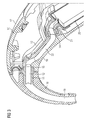
- FIG. 3 The front section of the BTE hearing aid is shown in almost fully assembled state in longitudinal section.
- the adapter 11 is inserted.
- a carrying hook 18 is mounted, which itself has a sound channel 19 from the adapter 11 to its tip.
- a receiver 20 is used in the housing 10, which generates the amplified sound. He has at its output a earpiece 21 through which its output sound is passed.
- FIG. 3 the cover piece 13 is shown in its final mounting position. Between the housing inner wall in the region of the lower portion 16 and the cover piece 13, a sound channel 22 is formed. The sound channel 22 extends over the entire width in the housing interior below the cover piece thirteenth
- a D-shaped sound channel instead of a sound tube or sound tube (round or rectangular cross-section) is obtained within the housing 10 in the present case.
- the cover piece 13 must be inserted into the housing 10, for example by ultrasonic welding or gluing.
- the space in the hearing aid housing can be better utilized with the same channel cross-section, so that the housing 10 or the hearing aid can be made smaller overall.
- the cover piece 13 is formed platelet-shaped. In principle, however, it can also assume any other shape in order to form the wall of the sound channel 22.
- the cover piece 13 can take on a further function, namely that of a carrier for a microphone of the hearing aid. Such a microphone is in FIG. 3 for the sake of clarity not shown, but can be placed in the space above the cover piece 13.
Landscapes
- Health & Medical Sciences (AREA)
- General Health & Medical Sciences (AREA)
- Neurosurgery (AREA)
- Otolaryngology (AREA)
- Physics & Mathematics (AREA)
- Engineering & Computer Science (AREA)
- Acoustics & Sound (AREA)
- Signal Processing (AREA)
- Headphones And Earphones (AREA)
- Measurement Of The Respiration, Hearing Ability, Form, And Blood Characteristics Of Living Organisms (AREA)
- Telephone Set Structure (AREA)
Abstract
Description
- Die vorliegende Erfindung betrifft eine Hörvorrichtung mit einem Gehäuse, einem Hörer, der in dem Gehäuse angeordnet ist, und einem Schallleitstück, durch das hindurch Schall von dem Hörer aus dem Gehäuse geleitet wird. Unter einer Hörvorrichtung wird hier jedes im oder am Ohr tragbare, schallausgebende Gerät verstanden, insbesondere ein Hörgerät, ein Headset, Kopfhörer und dergleichen.
- Hörgeräte sind tragbare Hörvorrichtungen, die zur Versorgung von Schwerhörenden dienen. Um den zahlreichen individuellen Bedürfnissen entgegenzukommen, werden unterschiedliche Bauformen von Hörgeräten wie Hinter-dem-Ohr-Hörgeräte (HdO), Hörgerät mit externem Hörer (RIC: receiver in the canal) und In-dem-Ohr-Hörgeräte (IdO), z.B. auch Concha-Hörgeräte oder Kanal-Hörgeräte (ITE, CIC), bereitgestellt. Die beispielhaft aufgeführten Hörgeräte werden am Außenohr oder im Gehörgang getragen. Darüber hinaus stehen auf dem Markt aber auch Knochenleitungshörhilfen, implantierbare oder vibrotaktile Hörhilfen zur Verfügung. Dabei erfolgt die Stimulation des geschädigten Gehörs entweder mechanisch oder elektrisch.
- Hörgeräte besitzen prinzipiell als wesentliche Komponenten einen Eingangswandler, einen Verstärker und einen Ausgangswandler. Der Eingangswandler ist in der Regel ein Schallempfänger, z. B. ein Mikrofon, und/oder ein elektromagnetischer Empfänger, z. B. eine Induktionsspule. Der Ausgangswandler ist meist als elektroakustischer Wandler, z. B. Miniaturlautsprecher, oder als elektromechanischer Wandler, z. B. Knochenleitungshörer, realisiert. Der Verstärker ist üblicherweise in eine Signalverarbeitungseinheit integriert. Dieser prinzipielle Aufbau ist in
FIG 1 am Beispiel eines Hinter-dem-Ohr-Hörgeräts dargestellt. In ein Hörgerätegehäuse 1 zum Tragen hinter dem Ohr sind ein oder mehrere Mikrofone 2 zur Aufnahme des Schalls aus der Umgebung eingebaut. Eine Signalverarbeitungseinheit 3, die ebenfalls in das Hörgerätegehäuse 1 integriert ist, verarbeitet die Mikrofonsignale und verstärkt sie. Das Ausgangssignal der Signalverarbeitungseinheit 3 wird an einen Lautsprecher bzw. Hörer 4 übertragen, der ein akustisches Signal ausgibt. Der Schall wird gegebenenfalls über einen Schallschlauch, der mit einer Otoplastik im Gehörgang fixiert ist, zum Trommelfell des Geräteträgers übertragen. Die Energieversorgung des Hörgeräts und insbesondere die der Signalverarbeitungseinheit 3 erfolgt durch eine ebenfalls ins Hörgerätegehäuse 1 integrierte Batterie 5. - In den meisten Hörgeräten ist innerhalb des Gehäuses ein Hörer vorgesehen, der den verstärkten Schall für den Hörgeräteträger erzeugt. Der Schall muss von dem Hörer aus dem Gehäuse des Hörgeräts heraus zum Gehörgang des Hörgeräteträgers übertragen werden. Diese Übertragungsstrecke erfordert mehrere Schallkanäle. Einige dieser Schallkanäle befinden sich innerhalb des Gehäuses und einige außerhalb des Gehäuses des Hörgeräts. Außerhalb des Hörgerätegehäuses befindet sich beispielsweise ein Schallkanal im Tragehaken des Hörgeräts und ein Schallkanal im Schallschlauch vom Tragehaken zum Gehörgang. Innerhalb des Hörgerätegehäuses befinden sich Schallkanäle im Hörerstutzen, vom Hörerstutzen zu einem Adapter, an dem der Tragehaken befestigt ist, und in dem Adapter selbst.
- Zwischen dem Hörerstutzen und dem Adapter im Inneren des Gehäuses wird bislang ein Schallschlauch verlegt, der einen bestimmten Querschnitt nicht unterschreiten darf. Bei zu geringem Querschnitt hätte der Schallschlauch oder das Rohr einen zu starken Tiefpasscharakter.
- Das Rohr von dem Hörer zu dem Adapter wird üblicherweise unter einem Mikrofon hindurch verlegt und verläuft damit meist am Boden des Hörgerätegehäuses, der die größte Gehäusequerschnittskrümmung aufweist. Für das Rohr bzw. den Schlauch ist entsprechend viel Platz unter dem Mikrofon vorzusehen.
- Die Aufgabe der vorliegenden Erfindung besteht darin, das Volumen einer Hörvorrichtung und insbesondere eines Hörgeräts zu reduzieren.
- Erfindungsgemäß wird diese Aufgabe gelöst durch eine Hörvorrichtung mit
- einem Gehäuse,
- einem Hörer, der in dem Gehäuse angeordnet ist, und
- einem Schallleitstück, durch das hindurch Schall von dem Hörer aus dem Gehäuse geleitet wird, sowie
- mit einem Deckstück, das in das Gehäuse so eingesetzt ist, dass sich ein Schallkanal zwischen dem Hörer und dem Schallleitstück bildet, wobei
- der Schallkanal seitlich durch das Gehäuse und das Deckstück begrenzt ist.
- In vorteilhafter Weise wird also ein Deckstück in das Gehäuse der Hörvorrichtung eingesetzt, sodass sich ein Schallkanal zwischen dem Hörer und einem Schallleitstück bildet, der durch das Gehäuse und das Deckstück seitlich begrenzt ist. Es wird also das Gehäuse als Schallkanalwand genutzt. Dies aber bedeutet, dass der gesamte Raum in dem Gehäuse unterhalb des Deckstücks als Schallkanal verwendet wird. Damit wird der Gehäuseinnenraum besser ausgenutzt, es verbleibt kein ungenutzter Raum im Gehäuse um einen Schallkanal herum, und das Gehäuse kann entsprechend kleiner gefertigt werden.
- In einer Ausführungsform kann das Gehäuse im Querschnitt in etwa eine D-Form besitzen, und ein Gehäuseabschnitt mit der größten Querschnittskrümmung den Schallkanal mitbilden. Diese D-Querschnittsform ist bei Hinter-dem-Ohr-Hörgeräten üblich, da sie an die Anatomie des Außenohrs angepasst ist. In dem Bereich der größten Querschnittskrümmung kann in der Regel kein Mikrofon eingebaut werden, sodass sich dieser Bereich für den Schallkanal anbietet und durch das Deckstück nun vollständig genutzt werden kann.
- Vorzugsweise besitzt das Deckstück im Wesentlichen eine plättchenförmige Gestalt. Das Deckstück ist somit einfach herstellbar und kann gleichzeitig als Auflage für ein Mikrofon verwendet werden.
- Darüber hinaus kann das Deckstück eine Öffnung als Eingang des Schallkanals aufweisen. Damit ergibt sich eine definierte Öffnung des Schallkanals, die beim Spritzen des Gehäuses noch nicht berücksichtigt werden muss.
- Um die Öffnung des Schallkanals kann am Deckstück ein Stutzen gebildet sein, auf den ein Hörerstutzen des Hörers gesteckt ist. Damit erfüllt das Deckstück zusätzlich die Funktion eines Adapters.
- Des Weiteren kann das Schallleitstück am anderen Ende des Schallkanals ein Adapter sein, der eine Schallverbindung zwischen einem Schallleitungskanal eines an dem Gehäuse befestigten Tragehakens und dem Schallkanal im Gehäuse bildet. Der Adapater hat dabei die Funktionalität sowohl der Schallleitung als auch der mechanischen Befestigung.
- Darüber hinaus kann in dem Gehäuse ein Mikrofon angeordnet sein, wobei der Schallkanal unter dem Mikrofon hindurchgeführt ist. Somit kann beispielsweise die Spitze, d. h. das schmalste Ende des Hörgerätegehäuses räumlich am besten ausgenutzt werden.
- Zudem kann der Schallkanal durch das Deckstück luftdicht gegenüber dem Innenraum des Gehäuses abgedichtet sein. Dadurch lassen sich Rückkopplungen im Inneren des Gehäuses vermeiden. Insbesondere kann das Deckstück an das Gehäuse geklebt oder geschweißt sein. Derartige Verbindungstechniken eignen sich speziell dafür, einen luftdichten Schallkanal zu erzielen.
- Wie oben bereits angedeutet wurde, ist es besonders vorteilhaft, die genannte Hörvorrichtung als Hinter-dem-Ohr-Hörgerät auszubilden. Durch die erfindungsgemäße Technik können kleinere Hörgeräte gebaut werden, sodass deren Akzeptanz steigt.
- Die vorliegende Erfindung ist anhand der beigefügten Zeichnungen näher erläutert, in denen zeigen:
- FIG 1
- den prinzipiellen Aufbau eines Hörgeräts gemäß dem Stand der Technik;
- FIG 2
- eine Explosionsdarstellung eines vorderen Abschnitts eines Hörgerätegehäuses und
- FIG 3
- einen Längsschnitt durch den vorderen Abschnitt eines Hörgeräts.
- Die nachfolgend näher geschilderten Ausführungsbeispiele stellen bevorzugte Ausführungsformen der vorliegenden Erfindung dar.
- In
FIG 2 ist ein Abschnitt eines Gehäuses 10 für ein HdO-Hörgerät wiedergegeben. Für Darstellungszwecke ist das Gehäuse 10 nach oben offen eingezeichnet. In die Stirnseite des Gehäuses 10 lässt sich ein Adapter 11 einfügen, der als Schallleitstück dient, um den im Gehäuse erzeugten Schall nach außen zu leiten. Dazu besitzt er eine entsprechende Bohrung 12. - Außerdem zeigt
FIG 2 ein Deckstück 13, das sich in das Gehäuse 10 einsetzen lässt. Das Deckstück 13 besitzt in etwa die Form eines länglichen Plättchens. An einem Ende ist ein Stutzen 14 vorgesehen, durch den der nach außen zu leitende Schall hindurchgeleitet wird. Am anderen Ende des Deckstücks 13 befindet sich eine Anschlussstelle 15, um eine schalldichte Verbindung zu dem Adapter 11 herzustellen (vergleicheFIG 3 ). - Das Gehäuse 10 besitzt im Querschnitt eine Form, die annähernd D-förmig ist. Dabei besitzt der untere Abschnitt 16 des Gehäuses eine deutlich stärkere Krümmung als der obere Abschnitt 17. Der untere Abschnitt 16 ist beim Tragen hinter dem Ohr nach unten gewandt und liegt in dem Spalt zwischen
- Ohrmuschel und Schädelknochen. Da der Innenraum im Gehäuse 10 im Bereich des unteren Abschnitts 16 sehr schmal ist, kann er für übliche Signalverarbeitungskomponenten wie Mikrofone, Hörer und Verstärker nicht genutzt werden. In den Raum im Bereich des unteren Abschnitts 16 wird erfindungsgemäß auch keine Schallröhre eingelegt, sondern der Raum wird insgesamt als Schallkanal genutzt. Nach oben hin wird dieser Raum durch das Deckstück 13 begrenzt.
- In
FIG 3 ist der vordere Abschnitt des HdO-Hörgeräts im nahezu vollständig montierten Zustand im Längsschnitt dargestellt. In das Gehäuse 10 ist der Adapter 11 eingesetzt. An den Adapter 11 ist ein Tragehaken 18 montiert, der selbst einen Schallkanal 19 vom Adapter 11 bis zu seiner Spitze besitzt. - Außerdem ist in das Gehäuse 10 ein Hörer 20 eingesetzt, der den verstärkten Schall erzeugt. Er besitzt an seinem Ausgang einen Hörerstutzen 21, durch den sein Ausgangsschall hindurchgeleitet wird.
- Darüber hinaus ist in
FIG 3 das Deckstück 13 in seiner endgültigen Montageposition dargestellt. Zwischen der Gehäuseinnenwand im Bereich des unteren Abschnitts 16 und dem Deckstück 13 ist ein Schallkanal 22 ausgebildet. Der Schallkanal 22 erstreckt sich über die gesamte Breite im Gehäuseinneren unterhalb des Deckstücks 13. - Auf den Stutzen 14 des Deckstücks 13 ist der Hörerstutzen 21 gesteckt. Tragehakenseitig ist die Anschlussstelle 15 des Deckstücks 13 mit dem Adapter 11 verbunden. Damit ergibt sich unterhalb des Deckstücks 13 der Schallkanal 22. Insgesamt ergibt sich damit eine Schallführung schalldicht von dem Hörer 20 durch den Hörerstutzen 21, den Schallkanal 22, den Kanal 12 im Adapter 11 und dem Kanal 19 im Tragehaken 18.
- Im vorliegenden Beispiel erhält man also innerhalb des Gehäuses 10 ein im vorliegenden Fall D-förmiger Schallkanal anstelle eines Schallröhrchens oder Schallschlauchs (runder oder rechteckiger Querschnitt). Zur Realisierung dieses Schallkanals 22 muss dann nur das Deckstück 13 in das Gehäuse 10 beispielsweise durch Ultraschallschweißen oder Kleben eingefügt werden. Insgesamt kann so bei gleichem Kanalquerschnitt der Raum im Hörgerätegehäuse besser ausgenutzt werden, sodass das Gehäuse 10 bzw. das Hörgerät insgesamt kleiner gebaut werden kann.
- Im vorliegenden Beispiel ist das Deckstück 13 plättchenförmig ausgebildet. Es kann aber grundsätzlich auch jede andere Form einnehmen, um die Wand des Schallkanals 22 zu bilden. Außerdem kann das Deckstück 13 eine weitere Funktion übernehmen, nämlich die eines Trägers für ein Mikrofon des Hörgeräts. Ein derartiges Mikrofon ist in
FIG 3 der Übersicht halber nicht eingezeichnet, kann aber in dem Raum oberhalb des Deckstücks 13 platziert werden.
Claims (10)
- Hörvorrichtung mit- einem Gehäuse (10),- einem Hörer (20), der in dem Gehäuse angeordnet ist, und- einem Schallleitstück (11), durch das hindurch Schall von dem Hörer aus dem Gehäuse geleitet wird,gekennzeichnet durch- ein Deckstück (13), das in das Gehäuse so eingesetzt ist, dass sich ein Schallkanal (22) zwischen dem Hörer und dem Schallleitstück bildet, wobei- der Schallkanal seitlich durch das Gehäuse und das Deckstück begrenzt ist.
- Hörvorrichtung nach Anspruch 1, wobei das Gehäuse (10) im Querschnitt in etwa eine D-Form besitzt, und ein Gehäuseabschnitt mit der größten Querschnittskrümmung den Schallkanal (22) mitbildet.
- Hörvorrichtung nach Anspruch 1 oder 2, wobei das Deckstück (13) im Wesentlichen eine plättchenförmige Gestalt besitzt.
- Hörvorrichtung nach einem der vorhergehenden Ansprüche, wobei das Deckstück (13) eine Öffnung als Eingang des Schallkanals aufweist.
- Hörvorrichtung nach Anspruch 4, wobei um die Öffnung ein Stutzen (14) des Deckstücks (13) gebildet ist, auf den ein Hörerstützen (21) des Hörers (20) aufgesteckt ist.
- Hörvorrichtung nach einem der vorhergehenden Ansprüche, wobei das Schallleitstück (11) ein Adapter ist, der eine Schallverbindung zwischen einem Schallleitungskanal (19) eines an dem Gehäuse (10) befestigten Tragehakens (18) und dem Schallkanal (22) im Gehäuse bildet.
- Hörvorrichtung nach einem der vorhergehenden Ansprüche, wobei in dem Gehäuse (10) ein Mikrofon angeordnet ist, und der Schallkanal (22) unter dem Mikrofon hindurchgeführt ist.
- Hörvorrichtung nach einem der vorhergehenden Ansprüche, wobei der Schallkanal (22) durch das Deckstück (13) luftdicht gegenüber dem Innenraum des Gehäuses (10) abgedichtet ist.
- Hörvorrichtung nach einem der vorhergehenden Ansprüche, wobei das Deckstück (13) an das Gehäuse (10) geklebt oder geschweißt ist.
- Hörvorrichtung nach einem der vorhergehenden Ansprüche, die als Hinter-dem-Ohr-Hörgerät ausgebildet ist.
Applications Claiming Priority (1)
| Application Number | Priority Date | Filing Date | Title |
|---|---|---|---|
| DE102011080123A DE102011080123B3 (de) | 2011-07-29 | 2011-07-29 | Hörvorrichtung mit speziellem Schallkanal |
Publications (2)
| Publication Number | Publication Date |
|---|---|
| EP2552129A1 true EP2552129A1 (de) | 2013-01-30 |
| EP2552129B1 EP2552129B1 (de) | 2015-06-17 |
Family
ID=46578907
Family Applications (1)
| Application Number | Title | Priority Date | Filing Date |
|---|---|---|---|
| EP12177639.7A Active EP2552129B1 (de) | 2011-07-29 | 2012-07-24 | Hörvorrichtung mit speziellem Schallkanal |
Country Status (5)
| Country | Link |
|---|---|
| US (1) | US8755551B2 (de) |
| EP (1) | EP2552129B1 (de) |
| CN (1) | CN102905216B (de) |
| DE (1) | DE102011080123B3 (de) |
| DK (1) | DK2552129T3 (de) |
Families Citing this family (2)
| Publication number | Priority date | Publication date | Assignee | Title |
|---|---|---|---|---|
| DE102014200917A1 (de) * | 2014-01-20 | 2015-07-23 | Siemens Medical Instruments Pte. Ltd. | HdO-Hörinstrument mit Gehäuse und Schallschlauch |
| DE102015208845B3 (de) * | 2015-05-13 | 2016-08-11 | Sivantos Pte. Ltd. | Hörgerät |
Citations (5)
| Publication number | Priority date | Publication date | Assignee | Title |
|---|---|---|---|---|
| DE4327634C1 (de) * | 1993-08-17 | 1994-06-30 | Siemens Audiologische Technik | Hinter dem Ohr zu tragendes Hörhilfegerät |
| JPH08251698A (ja) * | 1995-03-07 | 1996-09-27 | Rion Co Ltd | 耳掛け式補聴器 |
| US20050020127A1 (en) * | 2003-07-22 | 2005-01-27 | Werner Fickweiler | Connection piece for hearing device support hook |
| EP1915032A2 (de) * | 2006-10-18 | 2008-04-23 | Siemens Audiologische Technik GmbH | Hörhilfegerät |
| EP1962555A2 (de) * | 2007-02-22 | 2008-08-27 | Siemens Audiologische Technik GmbH | Hinter-dem-Ohr-Hörgerät mit magnetisch befestigtem Ohrhaken |
Family Cites Families (6)
| Publication number | Priority date | Publication date | Assignee | Title |
|---|---|---|---|---|
| DE2846346A1 (de) * | 1978-10-25 | 1980-05-08 | Bosch Gmbh Robert | Verfahren zum messen, pruefen und insbesondere zum einstellen des maximalen ausgangsschalldrucks von hoergeraeten |
| US6658125B1 (en) * | 1998-10-07 | 2003-12-02 | Oticon A/S | Hearing aid |
| DE59915251D1 (de) * | 1999-06-16 | 2011-04-07 | Phonak Ag | Hinterohr-hörgerät |
| DE10214189B4 (de) | 2002-03-28 | 2004-04-22 | Siemens Audiologische Technik Gmbh | Vorrichtung zum Beschallen eines Trommelfells mit einer Cerumenschutzeinrichtung und Hörgerät |
| US7715580B2 (en) * | 2006-03-21 | 2010-05-11 | Widex A/S | Interchangeable attachment means for attaching a conductor to a hearing aid |
| DE102007046052A1 (de) * | 2007-09-26 | 2009-04-09 | Siemens Medical Instruments Pte. Ltd. | Schallschlauch für eine Hörvorrichtung |
-
2011
- 2011-07-29 DE DE102011080123A patent/DE102011080123B3/de not_active Expired - Fee Related
-
2012
- 2012-07-24 CN CN201210257632.7A patent/CN102905216B/zh active Active
- 2012-07-24 DK DK12177639.7T patent/DK2552129T3/da active
- 2012-07-24 EP EP12177639.7A patent/EP2552129B1/de active Active
- 2012-07-30 US US13/561,544 patent/US8755551B2/en active Active
Patent Citations (5)
| Publication number | Priority date | Publication date | Assignee | Title |
|---|---|---|---|---|
| DE4327634C1 (de) * | 1993-08-17 | 1994-06-30 | Siemens Audiologische Technik | Hinter dem Ohr zu tragendes Hörhilfegerät |
| JPH08251698A (ja) * | 1995-03-07 | 1996-09-27 | Rion Co Ltd | 耳掛け式補聴器 |
| US20050020127A1 (en) * | 2003-07-22 | 2005-01-27 | Werner Fickweiler | Connection piece for hearing device support hook |
| EP1915032A2 (de) * | 2006-10-18 | 2008-04-23 | Siemens Audiologische Technik GmbH | Hörhilfegerät |
| EP1962555A2 (de) * | 2007-02-22 | 2008-08-27 | Siemens Audiologische Technik GmbH | Hinter-dem-Ohr-Hörgerät mit magnetisch befestigtem Ohrhaken |
Also Published As
| Publication number | Publication date |
|---|---|
| US8755551B2 (en) | 2014-06-17 |
| DK2552129T3 (da) | 2015-09-28 |
| CN102905216A (zh) | 2013-01-30 |
| DE102011080123B3 (de) | 2012-10-11 |
| US20130028455A1 (en) | 2013-01-31 |
| EP2552129B1 (de) | 2015-06-17 |
| CN102905216B (zh) | 2015-06-17 |
Similar Documents
| Publication | Publication Date | Title |
|---|---|---|
| DE102008052681B3 (de) | Ohrstück mit Stegen | |
| EP1993324B1 (de) | Ohrpassstück mit Adapterdichtung | |
| DE102007037024A1 (de) | Hörereinrichtung mit elastisch gelagertem Hörer | |
| EP1909536A2 (de) | Hinter-dem-Ohr-Hörgerät mit externem, optischem Mikrofon | |
| DE102012214976B3 (de) | Hörinstrument und Ohrstück mit Receiver | |
| EP2782363A1 (de) | Binaurales Hörinstrument sowie Ohrstück | |
| EP2219392B1 (de) | Microfonmodul für eine hörvorrichtung | |
| DE102010021173A1 (de) | Hörvorrichtung mit passiver, tief im Gehörgang sitzender Einheit | |
| EP1903835A2 (de) | Hörer mit zusätzlicher Abschirmeinrichtung | |
| DE102012205011A1 (de) | Hörinstrument mit flexibler Hörerschlauchverbindung | |
| EP2023665A1 (de) | Hörereinrichtung mit beeinflussbarer Schallaustrittsrichtung | |
| DE102007023055A1 (de) | Ohrstück für eine Hörvorrichtung mit Bajonettverschluss | |
| DE102011080609B4 (de) | Montage einer Signalverarbeitungskomponente in einem Gehäuse einer Hörvorrichtung | |
| EP2007172A1 (de) | Schallausgangsröhrchen mit 2-Komponenten-Aufbau | |
| EP2043387A1 (de) | Schallschlauch für eine Hörvorrichtung | |
| DE202011101299U1 (de) | Ohrschmuck zur Halterung eines Hörgerätes und Hörgerät in Kombination mit einem Ohrschmuck | |
| EP2552129B1 (de) | Hörvorrichtung mit speziellem Schallkanal | |
| EP2180725B1 (de) | Hörereinrichtung mit schwingungsentkoppeltem Hörer | |
| EP2360948A2 (de) | Werkzeug zum Montieren und Demontieren eines Hörers eines Hörgeräts | |
| EP2180723B1 (de) | Hörereinrichtung mit beweglichem Hörer | |
| WO2008089914A1 (de) | Hörgerät | |
| DE102013210170B4 (de) | Modulare Hörgerätegehäusevorrichtung für Hörgeräte | |
| DE102015226813A1 (de) | Hörgerät | |
| DE102010014213A1 (de) | Hörvorrichtung mit einer Hörhilfeeinheit und einer separaten Schnittstelleneinheit | |
| DE102009018425A1 (de) | Hörvorrichtung mit Entstörung am Signaleingang |
Legal Events
| Date | Code | Title | Description |
|---|---|---|---|
| PUAI | Public reference made under article 153(3) epc to a published international application that has entered the european phase |
Free format text: ORIGINAL CODE: 0009012 |
|
| AK | Designated contracting states |
Kind code of ref document: A1 Designated state(s): AL AT BE BG CH CY CZ DE DK EE ES FI FR GB GR HR HU IE IS IT LI LT LU LV MC MK MT NL NO PL PT RO RS SE SI SK SM TR |
|
| AX | Request for extension of the european patent |
Extension state: BA ME |
|
| 17P | Request for examination filed |
Effective date: 20130319 |
|
| GRAP | Despatch of communication of intention to grant a patent |
Free format text: ORIGINAL CODE: EPIDOSNIGR1 |
|
| INTG | Intention to grant announced |
Effective date: 20150122 |
|
| GRAS | Grant fee paid |
Free format text: ORIGINAL CODE: EPIDOSNIGR3 |
|
| GRAA | (expected) grant |
Free format text: ORIGINAL CODE: 0009210 |
|
| AK | Designated contracting states |
Kind code of ref document: B1 Designated state(s): AL AT BE BG CH CY CZ DE DK EE ES FI FR GB GR HR HU IE IS IT LI LT LU LV MC MK MT NL NO PL PT RO RS SE SI SK SM TR |
|
| REG | Reference to a national code |
Ref country code: GB Ref legal event code: FG4D Free format text: NOT ENGLISH |
|
| REG | Reference to a national code |
Ref country code: CH Ref legal event code: EP |
|
| REG | Reference to a national code |
Ref country code: AT Ref legal event code: REF Ref document number: 732466 Country of ref document: AT Kind code of ref document: T Effective date: 20150715 |
|
| REG | Reference to a national code |
Ref country code: IE Ref legal event code: FG4D Free format text: LANGUAGE OF EP DOCUMENT: GERMAN |
|
| REG | Reference to a national code |
Ref country code: DE Ref legal event code: R096 Ref document number: 502012003461 Country of ref document: DE |
|
| REG | Reference to a national code |
Ref country code: CH Ref legal event code: NV Representative=s name: E. BLUM AND CO. AG PATENT- UND MARKENANWAELTE , CH Ref country code: CH Ref legal event code: PFA Owner name: SIVANTOS PTE. LTD., SG Free format text: FORMER OWNER: SIEMENS MEDICAL INSTRUMENTS PTE. LTD., SG |
|
| REG | Reference to a national code |
Ref country code: DK Ref legal event code: T3 Effective date: 20150921 |
|
| REG | Reference to a national code |
Ref country code: DE Ref legal event code: R082 Ref document number: 502012003461 Country of ref document: DE Representative=s name: FDST PATENTANWAELTE FREIER DOERR STAMMLER TSCH, DE Ref country code: DE Ref legal event code: R081 Ref document number: 502012003461 Country of ref document: DE Owner name: SIVANTOS PTE. LTD., SG Free format text: FORMER OWNER: SIEMENS MEDICAL INSTRUMENTS PTE. LTD., SINGAPORE, SG |
|
| PG25 | Lapsed in a contracting state [announced via postgrant information from national office to epo] |
Ref country code: LT Free format text: LAPSE BECAUSE OF FAILURE TO SUBMIT A TRANSLATION OF THE DESCRIPTION OR TO PAY THE FEE WITHIN THE PRESCRIBED TIME-LIMIT Effective date: 20150617 Ref country code: NO Free format text: LAPSE BECAUSE OF FAILURE TO SUBMIT A TRANSLATION OF THE DESCRIPTION OR TO PAY THE FEE WITHIN THE PRESCRIBED TIME-LIMIT Effective date: 20150917 Ref country code: HR Free format text: LAPSE BECAUSE OF FAILURE TO SUBMIT A TRANSLATION OF THE DESCRIPTION OR TO PAY THE FEE WITHIN THE PRESCRIBED TIME-LIMIT Effective date: 20150617 Ref country code: FI Free format text: LAPSE BECAUSE OF FAILURE TO SUBMIT A TRANSLATION OF THE DESCRIPTION OR TO PAY THE FEE WITHIN THE PRESCRIBED TIME-LIMIT Effective date: 20150617 |
|
| REG | Reference to a national code |
Ref country code: CH Ref legal event code: PCOW Free format text: NEW ADDRESS: 28 AYER RAJAH CRESCENT 06-08, SINGAPORE 139959 (SG) |
|
| RAP2 | Party data changed (patent owner data changed or rights of a patent transferred) |
Owner name: SIVANTOS PTE. LTD. |
|
| REG | Reference to a national code |
Ref country code: LT Ref legal event code: MG4D Ref country code: NL Ref legal event code: MP Effective date: 20150617 |
|
| PG25 | Lapsed in a contracting state [announced via postgrant information from national office to epo] |
Ref country code: GR Free format text: LAPSE BECAUSE OF FAILURE TO SUBMIT A TRANSLATION OF THE DESCRIPTION OR TO PAY THE FEE WITHIN THE PRESCRIBED TIME-LIMIT Effective date: 20150918 Ref country code: RS Free format text: LAPSE BECAUSE OF FAILURE TO SUBMIT A TRANSLATION OF THE DESCRIPTION OR TO PAY THE FEE WITHIN THE PRESCRIBED TIME-LIMIT Effective date: 20150617 Ref country code: BG Free format text: LAPSE BECAUSE OF FAILURE TO SUBMIT A TRANSLATION OF THE DESCRIPTION OR TO PAY THE FEE WITHIN THE PRESCRIBED TIME-LIMIT Effective date: 20150917 Ref country code: LV Free format text: LAPSE BECAUSE OF FAILURE TO SUBMIT A TRANSLATION OF THE DESCRIPTION OR TO PAY THE FEE WITHIN THE PRESCRIBED TIME-LIMIT Effective date: 20150617 |
|
| PG25 | Lapsed in a contracting state [announced via postgrant information from national office to epo] |
Ref country code: EE Free format text: LAPSE BECAUSE OF FAILURE TO SUBMIT A TRANSLATION OF THE DESCRIPTION OR TO PAY THE FEE WITHIN THE PRESCRIBED TIME-LIMIT Effective date: 20150617 |
|
| PG25 | Lapsed in a contracting state [announced via postgrant information from national office to epo] |
Ref country code: ES Free format text: LAPSE BECAUSE OF FAILURE TO SUBMIT A TRANSLATION OF THE DESCRIPTION OR TO PAY THE FEE WITHIN THE PRESCRIBED TIME-LIMIT Effective date: 20150617 Ref country code: RO Free format text: LAPSE BECAUSE OF NON-PAYMENT OF DUE FEES Effective date: 20150617 Ref country code: CZ Free format text: LAPSE BECAUSE OF FAILURE TO SUBMIT A TRANSLATION OF THE DESCRIPTION OR TO PAY THE FEE WITHIN THE PRESCRIBED TIME-LIMIT Effective date: 20150617 Ref country code: PT Free format text: LAPSE BECAUSE OF FAILURE TO SUBMIT A TRANSLATION OF THE DESCRIPTION OR TO PAY THE FEE WITHIN THE PRESCRIBED TIME-LIMIT Effective date: 20151019 Ref country code: IS Free format text: LAPSE BECAUSE OF FAILURE TO SUBMIT A TRANSLATION OF THE DESCRIPTION OR TO PAY THE FEE WITHIN THE PRESCRIBED TIME-LIMIT Effective date: 20151017 Ref country code: SK Free format text: LAPSE BECAUSE OF FAILURE TO SUBMIT A TRANSLATION OF THE DESCRIPTION OR TO PAY THE FEE WITHIN THE PRESCRIBED TIME-LIMIT Effective date: 20150617 Ref country code: PL Free format text: LAPSE BECAUSE OF FAILURE TO SUBMIT A TRANSLATION OF THE DESCRIPTION OR TO PAY THE FEE WITHIN THE PRESCRIBED TIME-LIMIT Effective date: 20150617 |
|
| REG | Reference to a national code |
Ref country code: DE Ref legal event code: R097 Ref document number: 502012003461 Country of ref document: DE |
|
| PG25 | Lapsed in a contracting state [announced via postgrant information from national office to epo] |
Ref country code: MC Free format text: LAPSE BECAUSE OF FAILURE TO SUBMIT A TRANSLATION OF THE DESCRIPTION OR TO PAY THE FEE WITHIN THE PRESCRIBED TIME-LIMIT Effective date: 20150617 |
|
| REG | Reference to a national code |
Ref country code: IE Ref legal event code: MM4A |
|
| PLBE | No opposition filed within time limit |
Free format text: ORIGINAL CODE: 0009261 |
|
| STAA | Information on the status of an ep patent application or granted ep patent |
Free format text: STATUS: NO OPPOSITION FILED WITHIN TIME LIMIT |
|
| PG25 | Lapsed in a contracting state [announced via postgrant information from national office to epo] |
Ref country code: IT Free format text: LAPSE BECAUSE OF FAILURE TO SUBMIT A TRANSLATION OF THE DESCRIPTION OR TO PAY THE FEE WITHIN THE PRESCRIBED TIME-LIMIT Effective date: 20150617 |
|
| 26N | No opposition filed |
Effective date: 20160318 |
|
| REG | Reference to a national code |
Ref country code: FR Ref legal event code: PLFP Year of fee payment: 5 |
|
| PG25 | Lapsed in a contracting state [announced via postgrant information from national office to epo] |
Ref country code: IE Free format text: LAPSE BECAUSE OF NON-PAYMENT OF DUE FEES Effective date: 20150724 |
|
| PG25 | Lapsed in a contracting state [announced via postgrant information from national office to epo] |
Ref country code: SI Free format text: LAPSE BECAUSE OF FAILURE TO SUBMIT A TRANSLATION OF THE DESCRIPTION OR TO PAY THE FEE WITHIN THE PRESCRIBED TIME-LIMIT Effective date: 20150617 |
|
| PG25 | Lapsed in a contracting state [announced via postgrant information from national office to epo] |
Ref country code: MT Free format text: LAPSE BECAUSE OF FAILURE TO SUBMIT A TRANSLATION OF THE DESCRIPTION OR TO PAY THE FEE WITHIN THE PRESCRIBED TIME-LIMIT Effective date: 20150617 |
|
| PG25 | Lapsed in a contracting state [announced via postgrant information from national office to epo] |
Ref country code: HU Free format text: LAPSE BECAUSE OF FAILURE TO SUBMIT A TRANSLATION OF THE DESCRIPTION OR TO PAY THE FEE WITHIN THE PRESCRIBED TIME-LIMIT; INVALID AB INITIO Effective date: 20120724 Ref country code: SM Free format text: LAPSE BECAUSE OF FAILURE TO SUBMIT A TRANSLATION OF THE DESCRIPTION OR TO PAY THE FEE WITHIN THE PRESCRIBED TIME-LIMIT Effective date: 20150617 |
|
| PG25 | Lapsed in a contracting state [announced via postgrant information from national office to epo] |
Ref country code: NL Free format text: LAPSE BECAUSE OF FAILURE TO SUBMIT A TRANSLATION OF THE DESCRIPTION OR TO PAY THE FEE WITHIN THE PRESCRIBED TIME-LIMIT Effective date: 20150617 Ref country code: SE Free format text: LAPSE BECAUSE OF FAILURE TO SUBMIT A TRANSLATION OF THE DESCRIPTION OR TO PAY THE FEE WITHIN THE PRESCRIBED TIME-LIMIT Effective date: 20150617 Ref country code: CY Free format text: LAPSE BECAUSE OF FAILURE TO SUBMIT A TRANSLATION OF THE DESCRIPTION OR TO PAY THE FEE WITHIN THE PRESCRIBED TIME-LIMIT Effective date: 20150617 |
|
| REG | Reference to a national code |
Ref country code: FR Ref legal event code: PLFP Year of fee payment: 6 |
|
| PG25 | Lapsed in a contracting state [announced via postgrant information from national office to epo] |
Ref country code: BE Free format text: LAPSE BECAUSE OF NON-PAYMENT OF DUE FEES Effective date: 20150731 |
|
| PG25 | Lapsed in a contracting state [announced via postgrant information from national office to epo] |
Ref country code: TR Free format text: LAPSE BECAUSE OF FAILURE TO SUBMIT A TRANSLATION OF THE DESCRIPTION OR TO PAY THE FEE WITHIN THE PRESCRIBED TIME-LIMIT Effective date: 20150617 |
|
| PG25 | Lapsed in a contracting state [announced via postgrant information from national office to epo] |
Ref country code: LU Free format text: LAPSE BECAUSE OF NON-PAYMENT OF DUE FEES Effective date: 20150724 |
|
| PG25 | Lapsed in a contracting state [announced via postgrant information from national office to epo] |
Ref country code: MK Free format text: LAPSE BECAUSE OF FAILURE TO SUBMIT A TRANSLATION OF THE DESCRIPTION OR TO PAY THE FEE WITHIN THE PRESCRIBED TIME-LIMIT Effective date: 20150617 |
|
| REG | Reference to a national code |
Ref country code: FR Ref legal event code: PLFP Year of fee payment: 7 |
|
| REG | Reference to a national code |
Ref country code: AT Ref legal event code: MM01 Ref document number: 732466 Country of ref document: AT Kind code of ref document: T Effective date: 20170724 |
|
| PG25 | Lapsed in a contracting state [announced via postgrant information from national office to epo] |
Ref country code: AL Free format text: LAPSE BECAUSE OF FAILURE TO SUBMIT A TRANSLATION OF THE DESCRIPTION OR TO PAY THE FEE WITHIN THE PRESCRIBED TIME-LIMIT Effective date: 20150617 |
|
| PG25 | Lapsed in a contracting state [announced via postgrant information from national office to epo] |
Ref country code: AT Free format text: LAPSE BECAUSE OF NON-PAYMENT OF DUE FEES Effective date: 20170724 |
|
| PGFP | Annual fee paid to national office [announced via postgrant information from national office to epo] |
Ref country code: GB Payment date: 20240723 Year of fee payment: 13 |
|
| PGFP | Annual fee paid to national office [announced via postgrant information from national office to epo] |
Ref country code: FR Payment date: 20240724 Year of fee payment: 13 |
|
| PGFP | Annual fee paid to national office [announced via postgrant information from national office to epo] |
Ref country code: DK Payment date: 20250619 Year of fee payment: 14 |
|
| PGFP | Annual fee paid to national office [announced via postgrant information from national office to epo] |
Ref country code: DE Payment date: 20250620 Year of fee payment: 14 |
|
| PGFP | Annual fee paid to national office [announced via postgrant information from national office to epo] |
Ref country code: CH Payment date: 20250801 Year of fee payment: 14 |
|
| GBPC | Gb: european patent ceased through non-payment of renewal fee |
Effective date: 20250724 |
|
| PG25 | Lapsed in a contracting state [announced via postgrant information from national office to epo] |
Ref country code: GB Free format text: LAPSE BECAUSE OF NON-PAYMENT OF DUE FEES Effective date: 20250724 |
|
| PG25 | Lapsed in a contracting state [announced via postgrant information from national office to epo] |
Ref country code: FR Free format text: LAPSE BECAUSE OF NON-PAYMENT OF DUE FEES Effective date: 20250731 |