EP2551993B1 - Electromagnet for stator and manufacturing method of electromagnet for stator - Google Patents
Electromagnet for stator and manufacturing method of electromagnet for stator Download PDFInfo
- Publication number
- EP2551993B1 EP2551993B1 EP11759165.1A EP11759165A EP2551993B1 EP 2551993 B1 EP2551993 B1 EP 2551993B1 EP 11759165 A EP11759165 A EP 11759165A EP 2551993 B1 EP2551993 B1 EP 2551993B1
- Authority
- EP
- European Patent Office
- Prior art keywords
- winding
- line material
- notch
- stator
- flange
- Prior art date
- Legal status (The legal status is an assumption and is not a legal conclusion. Google has not performed a legal analysis and makes no representation as to the accuracy of the status listed.)
- Active
Links
Images


Classifications
-
- H—ELECTRICITY
- H02—GENERATION; CONVERSION OR DISTRIBUTION OF ELECTRIC POWER
- H02K—DYNAMO-ELECTRIC MACHINES
- H02K3/00—Details of windings
- H02K3/46—Fastening of windings on the stator or rotor structure
- H02K3/52—Fastening salient pole windings or connections thereto
- H02K3/521—Fastening salient pole windings or connections thereto applicable to stators only
- H02K3/522—Fastening salient pole windings or connections thereto applicable to stators only for generally annular cores with salient poles
-
- H—ELECTRICITY
- H02—GENERATION; CONVERSION OR DISTRIBUTION OF ELECTRIC POWER
- H02K—DYNAMO-ELECTRIC MACHINES
- H02K15/00—Methods or apparatus specially adapted for manufacturing, assembling, maintaining or repairing of dynamo-electric machines
- H02K15/04—Methods or apparatus specially adapted for manufacturing, assembling, maintaining or repairing of dynamo-electric machines of windings, prior to mounting into machines
- H02K15/0435—Wound windings
- H02K15/0442—Loop windings
- H02K15/045—Form wound coils
-
- H—ELECTRICITY
- H02—GENERATION; CONVERSION OR DISTRIBUTION OF ELECTRIC POWER
- H02K—DYNAMO-ELECTRIC MACHINES
- H02K15/00—Methods or apparatus specially adapted for manufacturing, assembling, maintaining or repairing of dynamo-electric machines
- H02K15/0056—Manufacturing winding connections
- H02K15/0068—Connecting winding sections; Forming leads; Connecting leads to terminals
- H02K15/0081—Connecting winding sections; Forming leads; Connecting leads to terminals for form-wound windings
-
- H—ELECTRICITY
- H02—GENERATION; CONVERSION OR DISTRIBUTION OF ELECTRIC POWER
- H02K—DYNAMO-ELECTRIC MACHINES
- H02K2203/00—Specific aspects not provided for in the other groups of this subclass relating to the windings
- H02K2203/06—Machines characterised by the wiring leads, i.e. conducting wires for connecting the winding terminations
-
- H—ELECTRICITY
- H02—GENERATION; CONVERSION OR DISTRIBUTION OF ELECTRIC POWER
- H02K—DYNAMO-ELECTRIC MACHINES
- H02K2203/00—Specific aspects not provided for in the other groups of this subclass relating to the windings
- H02K2203/12—Machines characterised by the bobbins for supporting the windings
-
- Y—GENERAL TAGGING OF NEW TECHNOLOGICAL DEVELOPMENTS; GENERAL TAGGING OF CROSS-SECTIONAL TECHNOLOGIES SPANNING OVER SEVERAL SECTIONS OF THE IPC; TECHNICAL SUBJECTS COVERED BY FORMER USPC CROSS-REFERENCE ART COLLECTIONS [XRACs] AND DIGESTS
- Y10—TECHNICAL SUBJECTS COVERED BY FORMER USPC
- Y10T—TECHNICAL SUBJECTS COVERED BY FORMER US CLASSIFICATION
- Y10T29/00—Metal working
- Y10T29/49—Method of mechanical manufacture
- Y10T29/49002—Electrical device making
- Y10T29/4902—Electromagnet, transformer or inductor
Definitions
- the present invention relates to an electromagnet used for a stator of an electric motor or a generator and a manufacturing method thereof.
- JP2008-236854 A published by Japan Patent Office in 2008 proposes an electromagnet for a stator of an electric motor or a generator.
- This electromagnet for a stator is provided with a stator core formed of a back yoke and teeth projecting from the back yoke toward the center of the stator.
- An insulator is attached to an outer periphery of each tooth.
- the insulator has a winding barrel around which a coil is wound. Flanges are formed at respective ends of the winding barrel, one on a tooth base end side in the vicinity of the back yoke and another one on a tooth distal end side.
- a notch is formed in the flange on the tooth base end side.
- a line material of a coil is guided to the winding barrel from the outside of the flange on the tooth base end side through the notch.
- US 2009/243420 A1 discloses a rotational motor that includes a stator formed by a core member including: a magnetic core portion extending in a radial direction of the rotational motor and formed into a fixed shape in every cross section thereof extending orthogonally relative to the radial direction, a coil wound around the magnetic core portion to form a plurality of layers and an engagement member engaging with the coil.
- US 2006/087192 A1 discloses a switched reluctance machine that includes a stator body having a stator pole. A bobbin is located on the stator pole. A stator winding is disposed on the bobbin.
- US 2006/087192 A1 discloses an electric machine that includes a segmented or non-segmented stator and an end shield defining at least one opening therein.
- the machine also includes at least one winding having a lead end and an exit end, and at least one end cap coupled to the stator.
- the end cap defines first and second grooves which are respectively engaged with either the lead end or exit end of the winding. The end cap guides the lead and exit ends through the opening in the end shield.
- the line material When the coil line material is to be guided to the winding barrel from the outside of the flange on the tooth base end side through the notch, the line material is guided from an opening part of the notch to the inside of the notch in a state where the line material is oblique to a flange surface so that the line material does not interfere with the flanges on the both sides of the notch. At this time, if the line material is easily bent, the line material interferes with the flange, which might make it difficult to guide the line material to the notch. This interference between the line material and the flange lowers efficiency of a coiling work on the insulator and lowers positioning accuracy of a coiling start position of the winding on the winding barrel.
- the electromagnet comprises a stator core formed of a back yoke and a tooth projecting from the back yoke, an insulator attached to the tooth, and a coil wound around the insulator.
- the insulator comprises a winding barrel around which a coil is wound in a plurality of layers, a first flange formed at one end of the winding barrel and having a notch through which a coil line material passes, and a second flange formed at another end of the winding barrel. Projecting lengths of the first flange from the winding barrel on the both sides of the notch are set to be different from each other.
- a stator 1 is a collective name of a plurality of electromagnets 2 arranged around a rotor of an electric motor or a generator in which permanent magnets are arranged.
- the rotor In the electric motor, the rotor is rotated around a center axis by feeding power to coils so as to magnetize the electromagnets.
- the electromagnets In the generator, the electromagnets generate an electric current in the coils by means of relative rotation between the rotor and the stator 1 around the center axis.
- the stator 1 comprises a plurality of stator cores 10 connected in the circumferential direction around the center axis.
- the stator core 10 is made of a back yoke 11 and a tooth 12 projecting toward the center axis direction from the back yoke 11.
- the stator core 10 is constructed by laminating thin electromagnetic steel plates punched substantially in the T-shape.
- the laminated electromagnetic steel plates are integrated by dwell caulking or welding, for example, so that they do not separate from each other.
- a projection 11A is formed on a side face of the back yoke 11.
- a recess 11B is formed on another side face of the back yoke 11. The projection 11A fits in the recess 11B of an adjacent stator core 10.
- the tooth 12 comprises a main body 121 and a distal end part 122.
- the distal end part 122 is formed at a distal end of the main body 121 and has an enlarged width to form a tapered shape.
- Distal end faces of the teeth 12 form a circular shape around the center axis. These distal end faces represent magnetic poles of the electromagnets opposing the rotor.
- an insulator 20 is provided with a cylindrical winding barrel 21 attached to the outer periphery of the tooth 12 of the stator core 10.
- a first flange 22 in contact with the back yoke 11 is formed at one end on the back yoke 11 side of the winding barrel 21.
- a second flange 23 is formed so as to surround the distal end part 122 of the tooth 12 on the other end of the winding barrel 21.
- the insulator 20 is formed of an insulator such as a resin.
- a line material 40 of a coil is wound around the outer periphery of the winding barrel 21 with normal winding, for example, as shown in Fig. 8 .
- the flanges 22 and 23 on the both ends of the winding barrel 21 regulate the winding width of each winding layer of the line material 40 of the coil. In other words, the flanges 22 and 23 prevent protrusion of the coil to the outside of the insulator 20.
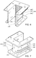
- the insulator 20 is made of a first component 20A shown in Figs. 3 and 4 and a second component 20B shown in Figs. 6 and 7 which are split in the laminating direction of the electromagnetic steel plate of the stator core 10, for the purpose of fitting onto the tooth 12.
- the first component 20A and the second component 20B are engaged with each other to cover the tooth 12 from the both sides thereof in the direction of the center axis of the stator 1.
- the first component 20A comprises a winding-barrel element 21A having a U-shaped cross-section, a flange element 22A formed at one end on the back yoke 11 side of the winding-barrel element 21A, and a flange element 23A formed at another end of the winding-barrel element 21A, which is farther from the back yoke 11.
- the second component 20B comprises a winding-barrel element 21B having a U-shaped cross-section, a flange element 22B formed at one end on the back yoke 11 side of the winding-barrel element 21B, and a flange element 23B formed at another end of the winding-barrel element 21B, which is farther from the back yoke 11.
- split structure of the insulator 20 a split structure other than the above-described split structure such as splitting the insulator 20 in a direction orthogonal to the laminating direction of the electromagnetic steel plates of the stator core 10, or in other words, splitting the insulator 20 in a circumferential direction of the stator core 10 is also possible. Moreover, splitting the insulator 20 into three to four elements at arbitrary split positions on the outer periphery of the tooth 12 is also possible.
- the first component 20A and the second component 20B when in an engaged state, form the cylindrical winding barrel 21 covering the tooth 12, the first flange 22 provided at the end of the back yoke 11 side of the winding barrel 21, and the second flange 23 provided at the another end of the winding barrel 21, which is farther from the back yoke 11.
- two band-shaped projections 24A and 24B are formed in the winding direction on one of the side faces directed to the connecting direction of the stator core 10 of the winding-barrel element 21A of the first component 20A.
- a single band-shaped projection 24C is formed in the winding direction.
- the formation position of the band-shaped projection 24C with respect to the radial direction of the stator 1 corresponds to the position between the formation positions of the band-shaped projection 24A and the band-shaped projection 24B.
- Plural parallel grooves 26A are formed in the radial direction of the stator 1 on a bottom surface 26 of the winding-barrel element 21A in contact with the end face of the tooth 12 with respect to the center axis direction of the stator 1.
- a thin fitting part 25A is formed in engaging parts of the winding-barrel element 21A, the flange element 22A, and the flange element 23A with the second component 20B.
- the thin fitting part 25A is formed by retreating a surface of the winding-barrel element 21A facing the tooth 12, a surface of the flange element 22A facing the back yoke 11, and a surface of the flange element 23A facing the distal end part 122 of the tooth 12 over a predetermined length, respectively.
- a tab 26B projecting outward in the radial direction of the stator 1 over a predetermined distance is fixed to the flange element 22A.
- the tab 26B defines, as shown in Fig. 1 , relative positions of the stator core 10 and the insulator 20 in the center axis direction of the stator 1 by being brought into contact with one of the end faces of the back yoke 11 with respect to the center axis direction of the stator 1.
- a rectangular notch 27 is formed for drawing a winding start part and a winding end part of the coil line material 40 that is wound around the outer periphery of the winding barrel 21 from the winding barrel 21 to the outside of the first flange 22.
- the notch 27 is formed in a part of the flange element 22A projecting from the stator core 1 in the center axis direction of the stator 1.
- a first portion 28A located on one side of the notch 27 and a second portion 28B located on an opposite side of the of the notch 27 to the first portion 28A are formed.
- the notch 27 and the first portion 28A and the second portion 28B of the flange element 22A are both located farther than the tab 26B from the winding barrel 21 in the center axis direction of the stator 1.
- the first portion 28A comprises a winding start positioning projection 30 abutting on the notch 27 and projecting outward in the radial direction of the stator 1.
- a first groove 31 is formed on the opposite side of the winding start positioning projection 30 to the notch 27.
- a guide surface 29 for guiding the line material 40 to the notch 27 through a space between the winding start positioning projection 30/first groove 31 and the tab 26B is formed in the first portion 28A.
- the guide surface 29 is formed as a slope inclined with respect to a bottom side of the notch 27 in order to smoothly guide the line material 40 when the line material 40 is introduced from the outside of the first flange 22 to the winding barrel 21 through the notch 27.
- the winding start positioning projection 30 performs positioning and locking by bending the winding start part of the line material 40 at the end of winding on the winding barrel 21.
- the first groove 31 prevents displacement of the winding start part of the line material 40 from the positioning position and also plays a role of locking the winding start part of the line material 40.
- the second portion 28B comprises a winding end positioning projection 33 abutting on the notch 27 and projecting outward in the radial direction of the stator 1.
- a second groove 34 is formed on the opposite side of the winding end positioning projection 33 to the notch 27.
- a notch 35 is formed in the winding end positioning projection 33 at a part opposing the tab 26B.
- the winding end positioning projection 33 performs positioning and locking by bending the winding end part of the line material 40 at the end of winding on the winding barrel 21.
- the notch 35 formed in the winding end positioning projection 33 prevents loosening of the line material 40 by holding the line material 40 in the bent state.
- the second groove 34 prevents displacement of the winding end part of the line material 40 from the positioning position and also plays a role of locking the winding end part of the line material 40.
- a projecting length L1 of the first portion 28A from the winding barrel 21 with respect to the axial direction of the stator 1 is set longer than a projecting length L2 of the second portion 28B from the winding barrel 21 with respect to the same direction.
- Such setting facilitates an operation of bending the line material 40 towards the winding barrel 21 by using the first portion 28A as a fulcrum when the line material 40 is guided to the winding barrel 21 from the outside of the first flange 22 through the notch 27 as shown in Fig. 11 .
- a corner part 30A facing the notch 27 of the first portion 28A is preferably formed to have a square shape.
- the corner part 30A is also a corner part of the winding start positioning projection 30.
- a corner part 33A facing the notch 27 of the second portion is formed having a circular shape.
- the corner part 33A is also a corner part of the winding end positioning projection 33. Setting of such shapes of the corner parts 30A and 33A further facilitates the operation of bending the line material 40 towards the winding barrel 21 by using the first portion 28A as a fulcrum.
- the depth of the first groove 31 is set deeper than the depth of the second groove 34 so that a bottom side of the first groove 31 and a bottom side of the second groove 34 are located substantially on the same line.
- distances of a start end of the line material 40 locked by the first groove 31 and a terminal end of the line material 40 locked by the second groove 34 from the stator core 10 are maintained equal. Locking the start end and the terminal end of the line material 40 at points of equal distance from the stator core 10 as described above facilitates fixation of the line material 40 of the coil to terminals 51 and 53 of a power collection and distribution bus ring 50 which will be described later.
- the two band-shaped projections 24A and 24B are provided in the winding direction on one side face of the winding-barrel element 21B of the second component 20B, and the single band-shaped projection 24C is provided in the winding direction on the other side face of the winding-barrel element 21B.
- the band-shaped projections 24A and 24B are formed continuous with the band-shaped projections 24A and 24B of the winding-barrel element 21A, respectively, on one side face of the winding-barrel element 21B directed to the connecting direction of the stator core 10.
- the band-shaped projection 24C is formed continuous with the band-shaped projection 24C of the winding-barrel element 21A on the other side face of the winding-barrel element 21B directed to the connecting direction of the stator core 10.
- a thin fitting part 25B is formed in engaging parts of the second component 20B with the first component 20A.
- the thin fitting part 25B is formed by retreating each surface facing the coil winding of the winding-barrel element 21B, flange element 22B, and the flange element 23B over a predetermined length, respectively.
- the thin fitting part 25A overlaps with the thin fitting part 25B, and the winding barrel 21, the first flange 22, and the second flange 23 are respectively integrated as shown in Fig. 1 .
- the coil winding on the insulator 20 is performed in a process shown in Fig. 9 to Fig. 18 in a state where the insulator 20 is attached to the stator core 10 as shown in Fig. 1 .
- Fig. 8 illustrates a state of the coil where the winding has been completed.
- Fig. 9 to Fig. 18 are overhead views of the insulator 20 seen from above showing a winding process
- Figs. 9 to 13 and Figs. 16 and 17 illustrate a state in which the recess 11B is directed in the horizontal direction
- Figs. 14 , 15 , and 18 illustrate a state in which the stator core 10 and the insulator 20 are rotated by substantially 90 degrees and the recess 11B is directed upward.
- the coil winding on the insulator 20 is performed in a state where the back yoke 11 of the stator core 10 is gripped by a coil winding jig T with respect to the laminating direction of the electromagnetic steel plates of the stator core 10, or in other words, in the center axis direction of the stator 1.
- the coil-winding jig T is driven to rotate by a rotating driving device. As the coil winding jig T rotates, the stator core 10 and the insulator 20 integrally rotates.
- the coil-winding jig T comprises a line-material retainer T1.
- the line-material retainer T1 holds the end portion of the line material 40 supplied from above in the figure by a line-material supplying device.
- the line-material retainer T1 holds a constant relative position with respect to the stator core 10 and the insulator 20.
- the line material 40 is wound around the winding barrel 21 of the insulator 20.
- the line-material supplying device supplies the line material 40 through a line material guide reciprocating in the center axis direction of the winding barrel 21 in accordance with the winding position of the line material 40 on the winding barrel 21.
- the line material 40 supplied from the line-material supplying device is held by the line-material retainer T1.
- the line material guide is adjusted so that the line material 40 is located above the back yoke 11, that is, so that the line material 40 is located outside the first flange 22 with respect to the center axis direction of the winding barrel 21.
- the line material guide is moved in a direction designated by an arrow in the figure, or in other words, the line material guide is moved towards the distal end of the tooth 12.
- the line material 40 held by the line-material retainer T1 at the end portion is thereby bent from the winding start positioning projection 30 towards the winding barrel 21 and guided to the notch 27 while being supported by the winding start positioning projection 30 formed on the first portion 28A of the first flange 22.
- the projecting length L1 of the first portion 28A from the winding barrel 21 is set longer than the projecting length L2 of the second portion 28B from the winding barrel 21.
- the extending direction of the line material 40 is slanted in advance with respect to the first flange 22 as shown in Fig. 26 , and the line material 40 is guided to the notch 27.
- a path that the line material 40 can take to pass through the notch 27 is limited to a narrow range illustrated by arrows in Fig. 26 . It is difficult to efficiently guide the line material 40 to the notch 27. If the path that the line material 40 can take is narrow, it becomes also difficult to guide the line material 40 having a bending tendency.
- the line material 40 can be bent in the horizontal direction by using the first portion 28A as a fulcrum and can be guided to the winding barrel 21 over the second portion 28B.
- the line material 40 guided to the notch 27 floats from the winding barrel 21 by a portion corresponding to the step H.
- the line material 40 wound in a layered state on top of the portion also floats from the winding barrel 21. As a result, the height of the coil end becomes high.
- the guide surface 29 which guides the line material 40 is formed on the first portion 28A in a space between the first groove 31/winding start positioning projection 30 and the tab 26B.
- the line material guide is moved to a direction designated by an arrow in the figure and the line material 40 is brought into contact with the second portion 28B of the first flange 22 so as to position the winding start of the line material 40 on the winding barrel 21.
- the line material 40 is wound around the winding barrel 21.
- the winding of the line material 40 on the winding barrel 21 reaches the second flange 23.
- the line material 40 is newly wound on the layer of the line material 40 having been already wound.
- the winding of the line material 40 is performed in several layers between the first flange 22 and the second flange 23.
- the line material guide is moved to the outside of the first flange 22 in parallel with the winding barrel 21 as illustrated by an arrow in the figure. With this movement, the line material 40 having finished the winding on the winding barrel 21 is taken out to the outside of the first flange 22 through the notch 27.
- the coil-winding jig T is further driven to rotate by substantially 90 degrees and stopped.
- the line material 40 having passed the notch 27 is locked by the notch 35 of the winding end positioning projection 33.
- the line material 40 is cut off between the notch 35 and the line material guide.
- the winding start portion of the line material 40 is cut off between the winding start positioning projection 30 of the first portion 28A and the line-material retainer T1.
- the winding of the line material 40 on the winding barrel 21 is completed as shown in Fig. 8 .
- the single electromagnet 2 is constructed.
- the predetermined number of electromagnets 2 constructed as above are sequentially connected by inserting the projection 11A of the back yoke 11 to the recess 11B of the adjacent back yoke 11 to constitute the ring-shaped stator 1.
- the ring-shaped stator 1 is arranged inside the power collection and distribution bus ring 50 provided on the housing of an electric motor or a generator.
- the power collection and distribution bus ring 50 has a terminal 51 for connecting a start end 40A of the coil of each electromagnet 2 and a terminal 52 for connecting a terminal end 40B of the coil of each electromagnet 2 alternately provided.
- the terminal 51 has a gap 51A, and the gap 51A is closed by tightening the terminal 51 by a tool in a state where the start end 40A is inserted into the gap 51A. The start end 40A is thereby held in a fixed manner.
- the terminal 52 has a gap 52A, and the gap 52A is closed by tightening the terminal 52 by a tool in a state where the terminal end 40B is inserted into the gap 52A. The terminal end 40B is thereby held in a fixed manner.
- the coil start end 40A has a taking-out position fixed by going around the winding start positioning projection 30.
- the coil terminal end 40B has a taking-out position fixed by going around the winding end positioning projection 33.
- the coil start end 40A and the terminal end 40B are held inside the locking grooves 31 and 34, respectively.
- the locking grooves 31 and 34 have a role of preventing displacement of the coil start end 40A and the terminal end 40B and of holding them at positioning positions when the plurality of electromagnets 2 are assembled to the ring-shaped stator 1 and when the assembled stator 1 is arranged inside the power collection and distribution bus ring 50. Therefore, the first groove 31 and the second groove 34 further facilitate the connection work of the start end 40A and the terminal end 40B to the terminals 51 and 52.
- positioning itself of the line material 40 can be made by the winding start positioning projection 30 and the winding end positioning projection 33. Therefore, it is possible to form only the notch 27, the winding start positioning projection 30, and the winding end positioning projection 33 on the first flange 22 as illustrated and to omit the first groove 31 and the second groove 34.
- This power collection and distribution bus ring 50 is provided with terminals 53 and 54 instead of the terminals 51 and 52 in Fig. 23 .
- the terminals 53 and 54 are supported by a support column 55 at positions overlapping with the locking grooves 31 and 34, respectively, with respect to the center axis direction of the stator 1.
- the terminal 53 has a gap 53A, and the gap 53A is closed by tightening the terminal 53 by a tool in a state where the start end 40A is inserted into the gap 53A, and the start end 40A is held in a fixed manner.
- the terminal 54 has a gap 54A, and the gap 54A is closed by tightening the terminal 54 by a tool in a state where the terminal end 40B is inserted into the gap 54A, and the start end 40B is held in a fixed manner.
- the terminals 53 and 54 are fixed to the support column 55 so that opening ends of the gaps 51A and 52A are directed to the center of the stator 1.
- the start end 40A and the terminal end 40B of the coil interfere with the terminals 53 and 54 when the ring-shaped stator 1 is inserted into the inside of the power collection and distribution bus ring 50.
- the first groove 31 and the second groove 34 in the first flange 22 and by inserting the ring-shaped stator 1 into the inside of the power collection and distribution bus ring 50 in a state where the coil start end 40A and the terminal end 40B are bent in the center direction of the stator 1 through the first groove 31 and the second groove 34, such interference can be prevented.
- the start end 40A and the terminal end 40B of the coil bent towards the center direction of the stator 1 through the first groove 31 and the second groove 34 are both straighten to a linear state so that they can be easily introduced into the gaps 53A and 54A.
- Tokugan2010-065753 The contents of Tokugan2010-065753 , with a filing date of March 23, 2010 in Japan, are referring to a further known related object.
- the line material 40 to be wound on the insulator 20 may have a square section or a circular section.
- the notch 27 is not limited to a rectangle but a U-shaped or V-shaped notch 27, for example, will do.
Description
- The present invention relates to an electromagnet used for a stator of an electric motor or a generator and a manufacturing method thereof.
-
JP2008-236854 A - This electromagnet for a stator is provided with a stator core formed of a back yoke and teeth projecting from the back yoke toward the center of the stator. An insulator is attached to an outer periphery of each tooth. The insulator has a winding barrel around which a coil is wound. Flanges are formed at respective ends of the winding barrel, one on a tooth base end side in the vicinity of the back yoke and another one on a tooth distal end side.
- A notch is formed in the flange on the tooth base end side. In coiling around the winding barrel, a line material of a coil is guided to the winding barrel from the outside of the flange on the tooth base end side through the notch.
-
DE 202 04 507 U1 discloses an electromagnet for a stator according to the preamble ofindependent claim 1. -
US 2009/243420 A1 discloses a rotational motor that includes a stator formed by a core member including: a magnetic core portion extending in a radial direction of the rotational motor and formed into a fixed shape in every cross section thereof extending orthogonally relative to the radial direction, a coil wound around the magnetic core portion to form a plurality of layers and an engagement member engaging with the coil. -
US 2006/087192 A1 discloses a switched reluctance machine that includes a stator body having a stator pole. A bobbin is located on the stator pole. A stator winding is disposed on the bobbin. -
US 2006/087192 A1 discloses an electric machine that includes a segmented or non-segmented stator and an end shield defining at least one opening therein. The machine also includes at least one winding having a lead end and an exit end, and at least one end cap coupled to the stator. The end cap defines first and second grooves which are respectively engaged with either the lead end or exit end of the winding. The end cap guides the lead and exit ends through the opening in the end shield. - When the coil line material is to be guided to the winding barrel from the outside of the flange on the tooth base end side through the notch, the line material is guided from an opening part of the notch to the inside of the notch in a state where the line material is oblique to a flange surface so that the line material does not interfere with the flanges on the both sides of the notch. At this time, if the line material is easily bent, the line material interferes with the flange, which might make it difficult to guide the line material to the notch. This interference between the line material and the flange lowers efficiency of a coiling work on the insulator and lowers positioning accuracy of a coiling start position of the winding on the winding barrel.
- It is therefore an object of this invention to guide the winding of a stator coil to the winding barrel through the notch in the flange easily and reliably.
- In order to achieve the above object, this invention provides an electromagnet for a stator according to
independent claim 1 and a manufacturing method of an electromagnet for a stator according to independent claim 7. According to an embodiment, the electromagnet comprises a stator core formed of a back yoke and a tooth projecting from the back yoke, an insulator attached to the tooth, and a coil wound around the insulator. The insulator comprises a winding barrel around which a coil is wound in a plurality of layers, a first flange formed at one end of the winding barrel and having a notch through which a coil line material passes, and a second flange formed at another end of the winding barrel. Projecting lengths of the first flange from the winding barrel on the both sides of the notch are set to be different from each other. - The details as well as other features and advantages of this invention are set forth in the remainder of the specification and are shown in the accompanying drawings.
-
-
Fig. 1 is a perspective view of an electromagnet for a stator according to an embodiment of this invention. -
Fig. 2 is a cross-sectional view of a stator core according to the embodiment of this invention. -
Fig. 3 is a perspective view of a first component forming an insulator according to the embodiment of this invention. -
Fig. 4 is a perspective view of the first component when seen from a different direction. -
Fig. 5 is an enlarged plan view of essential parts of a flange according to the first component of this invention. -
Fig. 6 is a perspective view of a second component forming the insulator together with the first component, according to the embodiment of this invention. -
Fig. 7 is a perspective view of the second component when seen from a different direction. -
Fig. 8 is a perspective view of a coil wound around the insulator according to the embodiment of this invention. -
Fig. 9 is an overhead view of the stator core and a jig according to the embodiment of this invention. -
Fig. 10 is an overhead view of the stator core, the jig, and a line material for explaining a first stage of a winding process of the coil on the insulator according to the embodiment of this invention. -
Fig. 11 is an overhead view of the stator core, the jig, and the line material for explaining a second stage of the winding process of the coil on the insulator according to the embodiment of this invention. -
Fig. 12 is an overhead view of the stator core, the jig, and the line material for explaining a third stage of the winding process of the coil on the insulator according to the embodiment of this invention. -
Fig. 13 is an overhead view of the stator core, the jig, and the line material for explaining a fourth stage of the winding process of the coil on the insulator according to the embodiment of this invention. -
Fig. 14 is an overhead view of the stator core, the jig, and the line material for explaining a fifth stage of the winding process of the coil on the insulator according to the embodiment of this invention. -
Fig. 15 is an overhead view of the stator core, the jig, and the line material for explaining a sixth stage of the winding process of the coil on the insulator according to the embodiment of this invention. -
Fig. 16 is an overhead view of the stator core, the jig, and the line material for explaining a seventh stage of the winding process of the coil on the insulator according to the embodiment of this invention. -
Fig. 17 is an overhead view of the stator core, the jig, and the line material for explaining an eighth stage of the winding process of the coil on the insulator according to the embodiment of this invention. -
Fig. 18 is an overhead view of the stator core, the jig, and the line material for explaining a ninth stage of the winding process of the coil on the insulator according to the embodiment of this invention. -
Fig. 19 is an enlarged plan view of the essential parts of the flange and the line material for explaining a situation of the second stage of the coil winding process. -
Fig. 20 is an enlarged overhead view of the essential parts of the flange and the line material for explaining the situation of the second stage of the coil winding process. -
Fig. 21 is an enlarged overhead view of the essential parts of the flange and the line material when the second stage of the coil winding process is completed. -
Figs. 22A - 22C are a plan view, a front view, and a side view of the flange for explaining a processing situation of beginning and end of winding of the coil. -
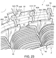
Fig. 23 is a perspective view of essential parts of the stator illustrating a connection state of a start end and a terminal end of the coil on a bus ring for power collection and distribution according to the embodiment of this invention. -
Fig. 24 is a perspective view of essential parts of the stator showing a variation of the bus ring for power collection and distribution. -
Fig. 25 is a perspective view of the insulator and the line material illustrating an introduction process of the line material into the notch in an electromagnet for a stator in a comparative example not according to this invention. -
Fig. 26 is an overhead view of the insulator and the line material illustrating the introduction process of the line material into the notch in the electromagnet for the stator in the comparative example not according to this invention. -
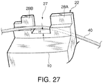
Fig. 27 is a perspective view of the insulator and the line material illustrating the state of completion of the introduction process of the line material into the notch in the electromagnet for the stator in the comparative example not according to this invention. - Referring to
Fig. 23 of the drawings, astator 1 is a collective name of a plurality ofelectromagnets 2 arranged around a rotor of an electric motor or a generator in which permanent magnets are arranged. - In the electric motor, the rotor is rotated around a center axis by feeding power to coils so as to magnetize the electromagnets. In the generator, the electromagnets generate an electric current in the coils by means of relative rotation between the rotor and the
stator 1 around the center axis. - Referring to
Fig. 2 , thestator 1 comprises a plurality ofstator cores 10 connected in the circumferential direction around the center axis. - The
stator core 10 is made of aback yoke 11 and atooth 12 projecting toward the center axis direction from theback yoke 11. Thestator core 10 is constructed by laminating thin electromagnetic steel plates punched substantially in the T-shape. The laminated electromagnetic steel plates are integrated by dwell caulking or welding, for example, so that they do not separate from each other. - A
projection 11A is formed on a side face of theback yoke 11. Arecess 11B is formed on another side face of theback yoke 11. Theprojection 11A fits in therecess 11B of anadjacent stator core 10. - The
tooth 12 comprises amain body 121 and adistal end part 122. Thedistal end part 122 is formed at a distal end of themain body 121 and has an enlarged width to form a tapered shape. Distal end faces of theteeth 12 form a circular shape around the center axis. These distal end faces represent magnetic poles of the electromagnets opposing the rotor. - Referring to
Fig. 16 , aninsulator 20 is provided with a cylindrical windingbarrel 21 attached to the outer periphery of thetooth 12 of thestator core 10. Afirst flange 22 in contact with theback yoke 11 is formed at one end on theback yoke 11 side of the windingbarrel 21. Asecond flange 23 is formed so as to surround thedistal end part 122 of thetooth 12 on the other end of the windingbarrel 21. Theinsulator 20 is formed of an insulator such as a resin. - A
line material 40 of a coil is wound around the outer periphery of the windingbarrel 21 with normal winding, for example, as shown inFig. 8 . Theflanges barrel 21 regulate the winding width of each winding layer of theline material 40 of the coil. In other words, theflanges insulator 20. - The
insulator 20 is made of afirst component 20A shown inFigs. 3 and 4 and asecond component 20B shown inFigs. 6 and 7 which are split in the laminating direction of the electromagnetic steel plate of thestator core 10, for the purpose of fitting onto thetooth 12. - Referring to
Fig. 1 , thefirst component 20A and thesecond component 20B are engaged with each other to cover thetooth 12 from the both sides thereof in the direction of the center axis of thestator 1. - For this purpose, the
first component 20A comprises a winding-barrel element 21A having a U-shaped cross-section, aflange element 22A formed at one end on theback yoke 11 side of the winding-barrel element 21A, and aflange element 23A formed at another end of the winding-barrel element 21A, which is farther from theback yoke 11. - Similarly, the
second component 20B comprises a winding-barrel element 21B having a U-shaped cross-section, aflange element 22B formed at one end on theback yoke 11 side of the winding-barrel element 21B, and aflange element 23B formed at another end of the winding-barrel element 21B, which is farther from theback yoke 11. - Regarding the split structure of the
insulator 20, a split structure other than the above-described split structure such as splitting theinsulator 20 in a direction orthogonal to the laminating direction of the electromagnetic steel plates of thestator core 10, or in other words, splitting theinsulator 20 in a circumferential direction of thestator core 10 is also possible. Moreover, splitting theinsulator 20 into three to four elements at arbitrary split positions on the outer periphery of thetooth 12 is also possible. - The
first component 20A and thesecond component 20B, when in an engaged state, form thecylindrical winding barrel 21 covering thetooth 12, thefirst flange 22 provided at the end of theback yoke 11 side of the windingbarrel 21, and thesecond flange 23 provided at the another end of the windingbarrel 21, which is farther from theback yoke 11. - Referring to
Figs. 3 and 4 , two band-shapedprojections stator core 10 of the winding-barrel element 21A of thefirst component 20A. On the other side face directed to the connecting direction of thestator core 10 of the winding-barrel element 21A, a single band-shapedprojection 24C is formed in the winding direction. The formation position of the band-shapedprojection 24C with respect to the radial direction of thestator 1 corresponds to the position between the formation positions of the band-shapedprojection 24A and the band-shapedprojection 24B. Pluralparallel grooves 26A are formed in the radial direction of thestator 1 on abottom surface 26 of the winding-barrel element 21A in contact with the end face of thetooth 12 with respect to the center axis direction of thestator 1. - A thin
fitting part 25A is formed in engaging parts of the winding-barrel element 21A, theflange element 22A, and theflange element 23A with thesecond component 20B. The thinfitting part 25A is formed by retreating a surface of the winding-barrel element 21A facing thetooth 12, a surface of theflange element 22A facing theback yoke 11, and a surface of theflange element 23A facing thedistal end part 122 of thetooth 12 over a predetermined length, respectively. - Continuously to the
bottom face 26 of the winding-barrel element 21A, atab 26B projecting outward in the radial direction of thestator 1 over a predetermined distance is fixed to theflange element 22A. Thetab 26B defines, as shown inFig. 1 , relative positions of thestator core 10 and theinsulator 20 in the center axis direction of thestator 1 by being brought into contact with one of the end faces of theback yoke 11 with respect to the center axis direction of thestator 1. - In the
flange element 22A, arectangular notch 27 is formed for drawing a winding start part and a winding end part of thecoil line material 40 that is wound around the outer periphery of the windingbarrel 21 from the windingbarrel 21 to the outside of thefirst flange 22. Thenotch 27 is formed in a part of theflange element 22A projecting from thestator core 1 in the center axis direction of thestator 1. - By forming the
notch 27, afirst portion 28A located on one side of thenotch 27 and asecond portion 28B located on an opposite side of the of thenotch 27 to thefirst portion 28A are formed. - Referring to
Fig. 5 , thenotch 27 and thefirst portion 28A and thesecond portion 28B of theflange element 22A are both located farther than thetab 26B from the windingbarrel 21 in the center axis direction of thestator 1. - The
first portion 28A comprises a windingstart positioning projection 30 abutting on thenotch 27 and projecting outward in the radial direction of thestator 1. In thefirst portion 28A, afirst groove 31 is formed on the opposite side of the windingstart positioning projection 30 to thenotch 27. Further, aguide surface 29 for guiding theline material 40 to thenotch 27 through a space between the windingstart positioning projection 30/first groove 31 and thetab 26B is formed in thefirst portion 28A. - Referring to
Fig. 22B , theguide surface 29 is formed as a slope inclined with respect to a bottom side of thenotch 27 in order to smoothly guide theline material 40 when theline material 40 is introduced from the outside of thefirst flange 22 to the windingbarrel 21 through thenotch 27. The windingstart positioning projection 30 performs positioning and locking by bending the winding start part of theline material 40 at the end of winding on the windingbarrel 21. Thefirst groove 31 prevents displacement of the winding start part of theline material 40 from the positioning position and also plays a role of locking the winding start part of theline material 40. - Referring to
Fig. 5 again, thesecond portion 28B comprises a windingend positioning projection 33 abutting on thenotch 27 and projecting outward in the radial direction of thestator 1. In thesecond portion 28B, asecond groove 34 is formed on the opposite side of the windingend positioning projection 33 to thenotch 27. Further, anotch 35 is formed in the windingend positioning projection 33 at a part opposing thetab 26B. - Referring to
Figs. 22B and 22C , the windingend positioning projection 33 performs positioning and locking by bending the winding end part of theline material 40 at the end of winding on the windingbarrel 21. Thenotch 35 formed in the windingend positioning projection 33 prevents loosening of theline material 40 by holding theline material 40 in the bent state. Thesecond groove 34 prevents displacement of the winding end part of theline material 40 from the positioning position and also plays a role of locking the winding end part of theline material 40. - Referring to
Fig. 5 again, a projecting length L1 of thefirst portion 28A from the windingbarrel 21 with respect to the axial direction of thestator 1 is set longer than a projecting length L2 of thesecond portion 28B from the windingbarrel 21 with respect to the same direction. - Such setting facilitates an operation of bending the
line material 40 towards the windingbarrel 21 by using thefirst portion 28A as a fulcrum when theline material 40 is guided to the windingbarrel 21 from the outside of thefirst flange 22 through thenotch 27 as shown inFig. 11 . - Moreover, a
corner part 30A facing thenotch 27 of thefirst portion 28A is preferably formed to have a square shape. Thecorner part 30A is also a corner part of the windingstart positioning projection 30. More preferably, acorner part 33A facing thenotch 27 of the second portion is formed having a circular shape. Thecorner part 33A is also a corner part of the windingend positioning projection 33. Setting of such shapes of thecorner parts line material 40 towards the windingbarrel 21 by using thefirst portion 28A as a fulcrum. - Referring to
Fig. 5 again, the depth of thefirst groove 31 is set deeper than the depth of thesecond groove 34 so that a bottom side of thefirst groove 31 and a bottom side of thesecond groove 34 are located substantially on the same line. As a result, distances of a start end of theline material 40 locked by thefirst groove 31 and a terminal end of theline material 40 locked by thesecond groove 34 from thestator core 10 are maintained equal. Locking the start end and the terminal end of theline material 40 at points of equal distance from thestator core 10 as described above facilitates fixation of theline material 40 of the coil toterminals distribution bus ring 50 which will be described later. - Referring to
Figs. 6 and 7 , the two band-shapedprojections barrel element 21B of thesecond component 20B, and the single band-shapedprojection 24C is provided in the winding direction on the other side face of the winding-barrel element 21B. - The band-shaped
projections projections barrel element 21A, respectively, on one side face of the winding-barrel element 21B directed to the connecting direction of thestator core 10. The band-shapedprojection 24C is formed continuous with the band-shapedprojection 24C of the winding-barrel element 21A on the other side face of the winding-barrel element 21B directed to the connecting direction of thestator core 10. - A thin
fitting part 25B is formed in engaging parts of thesecond component 20B with thefirst component 20A. The thinfitting part 25B is formed by retreating each surface facing the coil winding of the winding-barrel element 21B,flange element 22B, and theflange element 23B over a predetermined length, respectively. - In a state where the
first component 20A and thesecond component 20B are connected, the thinfitting part 25A overlaps with the thinfitting part 25B, and the windingbarrel 21, thefirst flange 22, and thesecond flange 23 are respectively integrated as shown inFig. 1 . - The coil winding on the
insulator 20 is performed in a process shown inFig. 9 to Fig. 18 in a state where theinsulator 20 is attached to thestator core 10 as shown inFig. 1 .Fig. 8 illustrates a state of the coil where the winding has been completed.Fig. 9 to Fig. 18 are overhead views of theinsulator 20 seen from above showing a winding process,Figs. 9 to 13 andFigs. 16 and17 illustrate a state in which therecess 11B is directed in the horizontal direction, whileFigs. 14 ,15 , and18 illustrate a state in which thestator core 10 and theinsulator 20 are rotated by substantially 90 degrees and therecess 11B is directed upward. - Referring to
Fig. 9 , the coil winding on theinsulator 20 is performed in a state where theback yoke 11 of thestator core 10 is gripped by a coil winding jig T with respect to the laminating direction of the electromagnetic steel plates of thestator core 10, or in other words, in the center axis direction of thestator 1. The coil-winding jig T is driven to rotate by a rotating driving device. As the coil winding jig T rotates, thestator core 10 and theinsulator 20 integrally rotates. The coil-winding jig T comprises a line-material retainer T1. - Referring to
Fig. 10 , the line-material retainer T1 holds the end portion of theline material 40 supplied from above in the figure by a line-material supplying device. The line-material retainer T1 holds a constant relative position with respect to thestator core 10 and theinsulator 20. When the line-material retainer T1 integrally rotates with the coil-winding jig T with respect to the line-material supplying device in a stationary state, theline material 40 is wound around the windingbarrel 21 of theinsulator 20. The line-material supplying device supplies theline material 40 through a line material guide reciprocating in the center axis direction of the windingbarrel 21 in accordance with the winding position of theline material 40 on the windingbarrel 21. - Prior to the operation of the coil-winding jig T to wind the
line material 40 on the windingbarrel 21, theline material 40 supplied from the line-material supplying device is held by the line-material retainer T1. At this time, the line material guide is adjusted so that theline material 40 is located above theback yoke 11, that is, so that theline material 40 is located outside thefirst flange 22 with respect to the center axis direction of the windingbarrel 21. - Referring to
Fig. 11 , the line material guide is moved in a direction designated by an arrow in the figure, or in other words, the line material guide is moved towards the distal end of thetooth 12. Theline material 40 held by the line-material retainer T1 at the end portion is thereby bent from the windingstart positioning projection 30 towards the windingbarrel 21 and guided to thenotch 27 while being supported by the windingstart positioning projection 30 formed on thefirst portion 28A of thefirst flange 22. - Here, as shown in
Fig. 5 , the projecting length L1 of thefirst portion 28A from the windingbarrel 21 is set longer than the projecting length L2 of thesecond portion 28B from the windingbarrel 21. - Referring to
Figs. 19 and 20 , by setting of the projecting lengths L1 and L2 as the above, interference between theline material 40 and thesecond portion 28B can be avoided when theline material 40 is bent toward the windingbarrel 21 by the line material guide by using the windingstart positioning projection 30 as a fulcrum. - Moreover, since the
line material 40 is bent while a tension is applied to theline material 40 by the line material guide and the line-material retainer T1, even theline material 40 having a bending tendency is reliably guided to the windingbarrel 21 through thenotch 27. - Referring to
Figs. 25 and26 , a case where the projecting lengths of thefirst portion 28A and thesecond portion 28B of thefirst flange 22 from the windingbarrel 21 are the same will be described. In this case, when theline material 40 is bent by using thefirst portion 28A as a fulcrum, theline material 40 is apt to interfere with thesecond portion 28B. - To avoid the interference, the extending direction of the
line material 40 is slanted in advance with respect to thefirst flange 22 as shown inFig. 26 , and theline material 40 is guided to thenotch 27. In this case, a path that theline material 40 can take to pass through thenotch 27 is limited to a narrow range illustrated by arrows inFig. 26 . It is difficult to efficiently guide theline material 40 to thenotch 27. If the path that theline material 40 can take is narrow, it becomes also difficult to guide theline material 40 having a bending tendency. - Referring to
Fig. 20 again, by setting the projecting length L1 of thefirst portion 28A from the windingbarrel 21 longer than the projecting length L2 of thesecond portion 28B from the windingbarrel 21 as in thisstator 1, theline material 40 can be bent in the horizontal direction by using thefirst portion 28A as a fulcrum and can be guided to the windingbarrel 21 over thesecond portion 28B. - Referring to
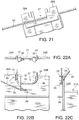
Fig. 21 , by driving the coil winding jig T to rotate and starting winding of theline material 40 on the windingbarrel 21 in this state, theline material 40 is reliably guided to the inside of thenotch 27. As described above, interference between theline material 40 and thefirst flange 22 is avoided without failure, and the winding start position of the winding can be positioned with precision. - Referring to
Fig. 27 , if a step H is present inside thefirst flange 22 on theback yoke 11 side, theline material 40 guided to thenotch 27 floats from the windingbarrel 21 by a portion corresponding to the step H. Theline material 40 wound in a layered state on top of the portion also floats from the windingbarrel 21. As a result, the height of the coil end becomes high. - In this
stator 1, theguide surface 29 which guides theline material 40 is formed on thefirst portion 28A in a space between thefirst groove 31/windingstart positioning projection 30 and thetab 26B. By forming theguide surface 29, even if there is the step H, theline material 40 reaching the windingbarrel 21 through thenotch 27 is reliably brought into contact with the surface of the windingbarrel 21. Therefore, floating of theline material 40 from the windingbarrel 21 can be prevented. - Referring to
Fig. 12 , after theline material 40 is guided to the windingbarrel 21 through thenotch 27, the line material guide is moved to a direction designated by an arrow in the figure and theline material 40 is brought into contact with thesecond portion 28B of thefirst flange 22 so as to position the winding start of theline material 40 on the windingbarrel 21. By driving the coil-winding jig T to rotate in this state, theline material 40 is wound around the windingbarrel 21. By moving the line material guide in parallel with the windingbarrel 21 in accordance with the winding, theline material 40 is wound side by side without a gap onto the windingbarrel 21. - Referring to
Fig. 13 , by continuing this winding work, the winding of theline material 40 on the windingbarrel 21 reaches thesecond flange 23. After that, by driving the coil-winding jig T to rotate while the line material guide is moved in the opposite direction in parallel with the windingbarrel 21, theline material 40 is newly wound on the layer of theline material 40 having been already wound. As described above, the winding of theline material 40 is performed in several layers between thefirst flange 22 and thesecond flange 23. - Referring to
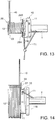
Fig. 14 , when the predetermined number of layers of winding is complete, the rotation of the coil winding jig T is stopped at a rotation position where theline material 40 comes to the vicinity of thenotch 27 of thefirst flange 22. This corresponds to a rotation position of thestator core 10 after the coil winding jig T is somewhat rotated from a position where the opening direction of therecess 11B becomes horizontal. - Referring to
Fig. 15 , in this state, the line material guide is moved to the outside of thefirst flange 22 in parallel with the windingbarrel 21 as illustrated by an arrow in the figure. With this movement, theline material 40 having finished the winding on the windingbarrel 21 is taken out to the outside of thefirst flange 22 through thenotch 27. - Referring to
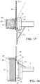
Fig. 16 , by driving the coil winding jig T to rotate by substantially 90 degrees from the state ofFig. 15 and by stopping it, theline material 40 is engaged with thenotch 35 of the windingend positioning projection 33 formed on thesecond portion 28B of thefirst flange 22. - Referring to
Fig. 17 , after theline material 40 is engaged with thenotch 35, the line material guide is moved in parallel with the windingbarrel 21 and in the direction opposite to that inFig. 15 as illustrated by an arrow in the figure again. - Referring to
Fig. 18 , the coil-winding jig T is further driven to rotate by substantially 90 degrees and stopped. As a result, theline material 40 having passed thenotch 27 is locked by thenotch 35 of the windingend positioning projection 33. In this state, theline material 40 is cut off between thenotch 35 and the line material guide. Moreover, the winding start portion of theline material 40 is cut off between the windingstart positioning projection 30 of thefirst portion 28A and the line-material retainer T1. As a result, the winding of theline material 40 on the windingbarrel 21 is completed as shown inFig. 8 . - In this state, as shown in
Fig. 22A , the winding end portion of theline material 40 passes through thenotch 27, goes around the windingend positioning projection 33 through thenotch 35 of the windingend positioning projection 33 and extends upward. As shown inFig. 22C , this portion is bent to the windingbarrel 21 side through the lockinggroove 34. The winding end portion of theline material 40 tends to become loose by a spring-back action of the coil caused by elasticity of theline material 40. In thisstator 1, after the winding end portion of theline material 40 is engaged with thenotch 35, theline material 40 goes around the windingend positioning projection 33 and is further bent to the windingbarrel 21 side from the lockinggroove 34 so as to prevent loosening of theline material 40. - The winding start portion of the
line material 40 after being cut off, as shown inFig. 22B , extends diagonally along theguide surface 29. This portion is bent upward by using the windingstart positioning projection 30 of thefirst portion 28A in the first flange as a guide and further bent to the windingbarrel 21 side through the lockinggroove 31 as shown inFig. 22C . Since the winding start portion of theline material 40 is pressed by the winding on the upper layer, the loosening is hardly generated, and by routing theline material 40 around the windingstart positioning projection 30 and then, bending it to the windingbarrel 21 side from the lockinggroove 31, the loosening of the winding start portion of theline material 40 is also prevented. - As described above, by attaching the
insulator 20 to thestator core 10 and by winding a coil on the windingbarrel 21 of theinsulator 20, thesingle electromagnet 2 is constructed. The predetermined number ofelectromagnets 2 constructed as above are sequentially connected by inserting theprojection 11A of theback yoke 11 to therecess 11B of theadjacent back yoke 11 to constitute the ring-shapedstator 1. - Referring to
Fig. 23 , the ring-shapedstator 1 is arranged inside the power collection anddistribution bus ring 50 provided on the housing of an electric motor or a generator. The power collection anddistribution bus ring 50 has a terminal 51 for connecting astart end 40A of the coil of eachelectromagnet 2 and a terminal 52 for connecting aterminal end 40B of the coil of eachelectromagnet 2 alternately provided. - The terminal 51 has a
gap 51A, and thegap 51A is closed by tightening the terminal 51 by a tool in a state where the start end 40A is inserted into thegap 51A. Thestart end 40A is thereby held in a fixed manner. Similarly, the terminal 52 has agap 52A, and thegap 52A is closed by tightening the terminal 52 by a tool in a state where theterminal end 40B is inserted into thegap 52A. Theterminal end 40B is thereby held in a fixed manner. - In each of the
electromagnets 2, the coil startend 40A has a taking-out position fixed by going around the windingstart positioning projection 30. The coilterminal end 40B has a taking-out position fixed by going around the windingend positioning projection 33. By setting the positions of the windingstart positioning projection 30 and the windingend positioning projection 33 so as to match intervals in the circumferential direction of theterminals terminal end 40B to the terminal 52 can be both performed with a shortest distance. - Moreover, in the
stator 1, the coil start end 40A and theterminal end 40B are held inside the lockinggrooves grooves terminal end 40B and of holding them at positioning positions when the plurality ofelectromagnets 2 are assembled to the ring-shapedstator 1 and when the assembledstator 1 is arranged inside the power collection anddistribution bus ring 50. Therefore, thefirst groove 31 and thesecond groove 34 further facilitate the connection work of the start end 40A and theterminal end 40B to theterminals - However, positioning itself of the
line material 40 can be made by the windingstart positioning projection 30 and the windingend positioning projection 33. Therefore, it is possible to form only thenotch 27, the windingstart positioning projection 30, and the windingend positioning projection 33 on thefirst flange 22 as illustrated and to omit thefirst groove 31 and thesecond groove 34. - Referring to
Fig. 24 , another configuration of the power collection anddistribution bus ring 50 will be described. - This power collection and
distribution bus ring 50 is provided withterminals terminals Fig. 23 . - The
terminals support column 55 at positions overlapping with the lockinggrooves stator 1. The terminal 53 has agap 53A, and thegap 53A is closed by tightening the terminal 53 by a tool in a state where the start end 40A is inserted into thegap 53A, and the start end 40A is held in a fixed manner. Similarly, the terminal 54 has agap 54A, and thegap 54A is closed by tightening the terminal 54 by a tool in a state where theterminal end 40B is inserted into thegap 54A, and thestart end 40B is held in a fixed manner. However, theterminals support column 55 so that opening ends of thegaps stator 1. - With the power collection and
distribution bus ring 50 having theterminals terminal end 40B of the coil interfere with theterminals stator 1 is inserted into the inside of the power collection anddistribution bus ring 50. By forming thefirst groove 31 and thesecond groove 34 in thefirst flange 22 and by inserting the ring-shapedstator 1 into the inside of the power collection anddistribution bus ring 50 in a state where the coil start end 40A and theterminal end 40B are bent in the center direction of thestator 1 through thefirst groove 31 and thesecond groove 34, such interference can be prevented. - In this case, after the
stator 1 is inserted at a predetermined position into the inside of the power collection anddistribution bus ring 50, the start end 40A and theterminal end 40B of the coil bent towards the center direction of thestator 1 through thefirst groove 31 and thesecond groove 34 are both straighten to a linear state so that they can be easily introduced into thegaps - The contents of
Tokugan2010-065753 - Although the invention has been described above with reference to certain embodiments, the invention is not limited to the embodiments described above. Rather, the invention is limited to the scope of protection defined in the claims.
- The
line material 40 to be wound on theinsulator 20 may have a square section or a circular section. Thenotch 27 is not limited to a rectangle but a U-shaped or V-shapednotch 27, for example, will do. - By using the stator to which the electromagnet according to this invention is applied, preferable effects can be obtained in rationalization of a manufacturing process of an electric motor and a generator and improvement in a manufacturing quality. The embodiments of this invention in which an exclusive property or privilege is claimed are defined as follows:
Claims (7)
- An electromagnet (2) for a stator comprising:
a stator core (10) formed of a back yoke (11) and a tooth (12) projecting from the back yoke (11):an insulator (20) attached to the tooth (12); anda coil wound around the insulator (20),whereinthe insulator (20) comprises a winding barrel (21) around which the coil is wound in a plurality of layers, a first flange (22) formed at one end of the winding barrel (21) adjacent to the back yoke (11), the first flange (22) having a notch (27) through which a line material (40) of the coil passes, and a second flange (23) formed at another end of the winding barrel (21) such that the line material (40) of the coil is guided to the winding barrel (21) through the notch (27) from an outside of the first flange (22), wound around the winding barrel (21), and taken out of the first flange (22) through the notch (27); andthe first flange (22) comprises a first portion (28A) located on a side of the notch (27) for positioning a winding start of the line material (40) and a second portion (28B) located on an opposite side of the notch (27) to the first portion (28A) for positioning a winding end of the line material (40),characterized in thata projecting length of the first portion (28a) from the winding barrel (21) is set to be longer than a projecting length of the second portion (28B) from the winding barrel (21). - The electromagnet (2) for a stator as defined in Claim 1, wherein the first portion (28A) comprises a square corner part (30A) abutting on the notch (27) and the second portion (28B) comprises a circular corner part (33A) abutting on the notch (27).
- The electromagnet (2) for a stator as defined in Claim 1 or Claim 2, wherein the second portion (28B) comprises a winding end positioning projection (33) projecting toward the back yoke (11) for positioning a winding end position of the line material (40) in the vicinity of the notch (27).
- The electromagnet (2) for a stator as defined in Claim 3, wherein the first portion (28A) comprises a winding start positioning projection (30) projecting toward the back yoke (11) for positioning a winding start position of the line material (40) in the vicinity of the notch (27).
- The electromagnet (2) for a stator as defined in Claim 4, wherein the first portion comprises a first groove (31) formed on an opposite side of the winding start positioning projection (30) to the notch (27) for positioning a start end of the line material (40), and the second portion (28B) comprises a second groove (34) formed on an opposite side of the winding end positioning projection (33) to the notch (27) for positioning a terminal end of the line material (40).
- The electromagnet (2) for a stator as defined In Claim 5, wherein a depth of the first groove (31) is set to be deeper than a depth of the second groove (34).
- A manufacturing method of an electromagnet (2) for a stator, comprising:attaching an insulator (20) to a tooth (12) of a stator core (10), the insulator (12) comprising a winding barrel (21), a first flange (22) formed at one end of the winding barrel (21) and having a notch (27) through which a line material (40) of a coil passes, and a second flange (23) formed at another end of the winding barrel (21), and the stator core (10) comprising a back yoke (11) from which the tooth (12) projects, wherein projecting lengths of the first flange (22) from the winding barrel (21) on both sides of the notch (27) are set to be different from each other;guiding the line material (40) of the coil to the winding barrel (21) from an outside of the first flange (22) through the notch (27);winding the line material (40) on the winding barrel (21) in a plurality of layers; andtaking out the line material (40) from the winding barrel (21) to the outside of the first flange (22) through the notch (27),wherein the first flange (22) comprises a first portion (28A) located on a side of the notch (27) for positioning a winding start of the line material (40) and a second portion (28B) located on an opposite side of the notch (27) to the first portion (28A) for positioning a winding end of the line material (40),characterized in thata projecting length of the first portion (28a) from the winding barrel (21) is set to be longer than a projecting length of the second portion (28B) from the winding barrel (21).
Applications Claiming Priority (2)
| Application Number | Priority Date | Filing Date | Title |
|---|---|---|---|
| JP2010065753A JP5636710B2 (en) | 2010-03-23 | 2010-03-23 | Insulator for rotating electrical machine and method for manufacturing stator winding structure |
| PCT/JP2011/054909 WO2011118357A1 (en) | 2010-03-23 | 2011-03-03 | Electromagnet for stator and method of manufacturing electromagnet for stator |
Publications (3)
| Publication Number | Publication Date |
|---|---|
| EP2551993A1 EP2551993A1 (en) | 2013-01-30 |
| EP2551993A4 EP2551993A4 (en) | 2017-10-11 |
| EP2551993B1 true EP2551993B1 (en) | 2018-06-06 |
Family
ID=44672925
Family Applications (1)
| Application Number | Title | Priority Date | Filing Date |
|---|---|---|---|
| EP11759165.1A Active EP2551993B1 (en) | 2010-03-23 | 2011-03-03 | Electromagnet for stator and manufacturing method of electromagnet for stator |
Country Status (5)
| Country | Link |
|---|---|
| US (1) | US9203274B2 (en) |
| EP (1) | EP2551993B1 (en) |
| JP (1) | JP5636710B2 (en) |
| CN (1) | CN102934331B (en) |
| WO (1) | WO2011118357A1 (en) |
Families Citing this family (30)
| Publication number | Priority date | Publication date | Assignee | Title |
|---|---|---|---|---|
| JP6033573B2 (en) * | 2012-04-27 | 2016-11-30 | 株式会社ニフコ | Insulator for stator |
| FR2992493B1 (en) * | 2012-06-20 | 2015-07-10 | Valeo Equip Electr Moteur | COIL INSULATION WITH A FINALLY WALL FORMING AN ELECTRICALLY INSULATING WALL AND ASSOCIATED ELECTRIC MACHINE ELEMENT |
| KR20140003674A (en) * | 2012-06-22 | 2014-01-10 | 엘지이노텍 주식회사 | Motor |
| KR101940516B1 (en) * | 2012-08-03 | 2019-04-11 | 삼성전자주식회사 | Motor and washing machine having the same |
| DE102012224012A1 (en) * | 2012-12-20 | 2014-06-26 | Tyco Electronics Belgium Ec Bvba | Spool for mounting on a magnetic core, reluctance resolver and method of manufacture |
| CN103928999B (en) * | 2013-01-10 | 2017-08-11 | 广东美的环境电器制造有限公司 | The bobbin winder bracket and its method for winding of stator, block-stator motor |
| DE102013204759A1 (en) | 2013-03-19 | 2014-09-25 | Robert Bosch Gmbh | Tooth segment for assembling a stator or rotor of an electric machine and method for the production of such |
| JP5928904B2 (en) | 2013-08-06 | 2016-06-01 | 株式会社安川電機 | Insulator, stator assembly, rotating electric machine, and wiring board |
| AU2013404182B2 (en) * | 2013-10-30 | 2016-09-15 | Mitsubishi Electric Corporation | Electric motor, compressor including the same, and method of manufacturing electric motor |
| JP6225804B2 (en) * | 2014-04-07 | 2017-11-08 | 株式会社安川電機 | Bobbins and rotating electrical machines |
| JP6801946B2 (en) * | 2015-01-20 | 2020-12-16 | トヨタ自動車株式会社 | Insulator formation method |
| US10038348B2 (en) * | 2015-08-12 | 2018-07-31 | Regal Beloit America, Inc. | Liner, stator assembly and associated method |
| CN105746757A (en) * | 2016-03-25 | 2016-07-13 | 梧州市中茗茶业有限公司 | Tea fermentation barrel |
| CN110291700B (en) * | 2017-02-13 | 2021-11-19 | Lg伊诺特有限公司 | Stator and motor comprising same |
| JP6700211B2 (en) * | 2017-03-15 | 2020-05-27 | アイチエレック株式会社 | Stator and electric motor |
| JP6656474B2 (en) * | 2017-06-02 | 2020-03-04 | デンソートリム株式会社 | Rotating electric machine |
| JP7314361B2 (en) * | 2017-06-14 | 2023-07-25 | 株式会社マキタ | Electric tool |
| DE112018002325T5 (en) | 2017-06-14 | 2020-01-23 | Makita Corporation | POWER TOOL |
| JP6994873B2 (en) * | 2017-08-29 | 2022-01-14 | 株式会社ミツバ | Brushless motor |
| WO2019058649A1 (en) | 2017-09-20 | 2019-03-28 | パナソニックIpマネジメント株式会社 | Insulator, and stator and motor comprising same |
| JP7209264B2 (en) | 2017-09-20 | 2023-01-20 | パナソニックIpマネジメント株式会社 | Insulators and stators and motors equipped with them |
| JPWO2019058644A1 (en) | 2017-09-20 | 2020-09-10 | パナソニックIpマネジメント株式会社 | Insulator and stator and motor equipped with it |
| CN107947420B (en) * | 2017-11-28 | 2020-05-05 | 广东美的环境电器制造有限公司 | Insulating frame for motor, insulating frame, motor stator and manufacturing method of motor stator |
| CN111566907A (en) * | 2018-01-24 | 2020-08-21 | 松下知识产权经营株式会社 | Insulator, stator including the same, and motor including the same |
| JP7004164B2 (en) * | 2018-03-30 | 2022-01-21 | 株式会社豊田自動織機 | Method for manufacturing rotary electric machine stator, rotary electric machine, and rotary electric machine stator |
| GB2577546B (en) * | 2018-09-28 | 2023-05-24 | Dyson Technology Ltd | A stator core assembly |
| JP7247720B2 (en) * | 2019-04-03 | 2023-03-29 | 株式会社プロテリアル | Radial gap type rotary electric machine and method for manufacturing radial gap type rotary electric machine |
| KR102317047B1 (en) * | 2019-07-25 | 2021-10-25 | 엘지전자 주식회사 | Stator and Motor having the same |
| JP2021083183A (en) * | 2019-11-15 | 2021-05-27 | 日本電産株式会社 | Stator and motor |
| JP2022178706A (en) * | 2021-05-20 | 2022-12-02 | 株式会社デンソー | Insulator, stator, and manufacturing method for the stator |
Family Cites Families (25)
| Publication number | Priority date | Publication date | Assignee | Title |
|---|---|---|---|---|
| JPH0510324Y2 (en) * | 1986-07-29 | 1993-03-15 | ||
| JP2002176753A (en) * | 2000-12-07 | 2002-06-21 | Matsushita Electric Ind Co Ltd | Stator for motor and manufacturing method thereof |
| JP2002284446A (en) * | 2001-03-23 | 2002-10-03 | Moric Co Ltd | Winding bobbin for electric device |
| JP3718473B2 (en) * | 2002-01-08 | 2005-11-24 | 草津電機株式会社 | Electric motor |
| DE20204507U1 (en) * | 2002-03-21 | 2002-06-06 | Grundfos As | Coil carrier as an insulating material for an electrical coil |
| JP3980402B2 (en) * | 2002-05-13 | 2007-09-26 | 本田技研工業株式会社 | Rotating electric machine |
| EP1437817B1 (en) * | 2003-01-10 | 2013-03-13 | Askoll Holding S.r.l. | Synchronous electric motor with a permanent magnet rotor and improved supporting spools for circulation pumps of heating and air-conditioning systems |
| US7026739B2 (en) * | 2003-05-23 | 2006-04-11 | Honda Motor Co., Ltd | Stator and insulating bobbin and a manufacturing method of the stator |
| DE10345631A1 (en) * | 2003-09-29 | 2005-05-04 | Siemens Ag | Electric machine with carrier device with measuring system |
| JP4483480B2 (en) * | 2004-08-27 | 2010-06-16 | アイシン精機株式会社 | Stator and motor |
| US20060071569A1 (en) * | 2004-10-04 | 2006-04-06 | Stewart William P | Stator end caps and methods for positioning the lead and exit ends of the stator windings |
| US7095150B2 (en) * | 2004-10-21 | 2006-08-22 | Shop Vac Corporation | Apparatus for securing a bobbin of a reluctance machine |
| JP2007014147A (en) * | 2005-06-30 | 2007-01-18 | Fujitsu General Ltd | Electric motor |
| JP4487914B2 (en) * | 2005-11-30 | 2010-06-23 | トヨタ自動車株式会社 | Cassette coil and rotating electric machine provided with cassette coil |
| DE102006021903A1 (en) * | 2006-05-11 | 2007-11-22 | Zf Friedrichshafen Ag | Winding body for receiving winding of electrical conductor, has winding area formed by winding carrier and legs that are connected with winding carrier, where winding carrier has profile for guiding electrical conductor |
| JP2008072801A (en) * | 2006-09-13 | 2008-03-27 | Mitsuba Corp | Coil device, stator, and motor |
| JP2008148470A (en) * | 2006-12-12 | 2008-06-26 | Hitachi Ltd | Concentrated winding coil and its manufacturing method |
| JP4697145B2 (en) * | 2007-01-18 | 2011-06-08 | トヨタ自動車株式会社 | Insulator bobbin and its assembly method |
| JP4791387B2 (en) * | 2007-02-21 | 2011-10-12 | 三菱電機株式会社 | Armature |
| JP5082524B2 (en) | 2007-03-19 | 2012-11-28 | 日産自動車株式会社 | Insulator, stator structure and manufacturing method |
| DE102007035531A1 (en) * | 2007-07-28 | 2009-01-29 | Zf Friedrichshafen Ag | Winding arrangement for electrical machine, has coil windings arranged at teeth and comprise inner region representing wedge surface, where one of windings is arranged at teeth by winding form |
| JP4967909B2 (en) * | 2007-08-02 | 2012-07-04 | 日産自動車株式会社 | Insulator, stator and stator manufacturing method |
| JP5315743B2 (en) * | 2008-03-26 | 2013-10-16 | アイシン精機株式会社 | Electric rotary motor |
| JP5153433B2 (en) * | 2008-04-22 | 2013-02-27 | 三菱電機株式会社 | Electric motor |
| JP4868187B2 (en) * | 2009-01-16 | 2012-02-01 | 株式会社富士通ゼネラル | Electric motor |
-
2010
- 2010-03-23 JP JP2010065753A patent/JP5636710B2/en active Active
-
2011
- 2011-03-03 US US13/635,995 patent/US9203274B2/en active Active
- 2011-03-03 CN CN201180012738.4A patent/CN102934331B/en active Active
- 2011-03-03 EP EP11759165.1A patent/EP2551993B1/en active Active
- 2011-03-03 WO PCT/JP2011/054909 patent/WO2011118357A1/en active Application Filing
Also Published As
| Publication number | Publication date |
|---|---|
| EP2551993A4 (en) | 2017-10-11 |
| US9203274B2 (en) | 2015-12-01 |
| EP2551993A1 (en) | 2013-01-30 |
| CN102934331B (en) | 2015-02-04 |
| WO2011118357A1 (en) | 2011-09-29 |
| JP5636710B2 (en) | 2014-12-10 |
| JP2011200059A (en) | 2011-10-06 |
| US20130009512A1 (en) | 2013-01-10 |
| CN102934331A (en) | 2013-02-13 |
Similar Documents
| Publication | Publication Date | Title |
|---|---|---|
| EP2551993B1 (en) | Electromagnet for stator and manufacturing method of electromagnet for stator | |
| JP6390772B2 (en) | Stator assembly method and stator assembly apparatus | |
| US10892659B2 (en) | Stator unit, rotary electric machine including stator unit, and method of manufacturing stator unit | |
| CN108886287B (en) | Magnetic pole, method for manufacturing magnetic pole, and stator | |
| US8836186B2 (en) | Bus bar device, stator, motor and manufacturing method for stator | |
| EP1793471A1 (en) | Armature, rotating electric machine, dc motor, and brushless motor | |
| EP3193428B1 (en) | Stator | |
| US10122226B2 (en) | Arrangement of coil wires in a rotor of an electric motor | |
| JP2012244842A (en) | Rotary electric machine | |
| JP6358086B2 (en) | Stator assembly apparatus and stator assembly method | |
| EP2738916B1 (en) | Stator of an electric motor comprising a coil insulation | |
| JP2011182603A (en) | Rotor, method of manufacturing the same, and motor | |
| US8256100B2 (en) | Stator manufacturing apparatus | |
| US11404930B2 (en) | Insulator, and stator and motor comprising same | |
| EP3687042B1 (en) | Insulator, and stator and motor comprising same | |
| US20030011269A1 (en) | Armature for revolving -field electric machine | |
| CN109586483B (en) | Motor and stator | |
| CN107925321B (en) | Method for manufacturing armature | |
| US20050034541A1 (en) | Rotation angle sensor having single wire windings and method for winding a rotation angle sensor | |
| JP5450193B2 (en) | Armature manufacturing method, motor manufacturing method, and armature manufacturing apparatus | |
| EP1276207A2 (en) | Armature for revolving field electrical machine |
Legal Events
| Date | Code | Title | Description |
|---|---|---|---|
| PUAI | Public reference made under article 153(3) epc to a published international application that has entered the european phase |
Free format text: ORIGINAL CODE: 0009012 |
|
| 17P | Request for examination filed |
Effective date: 20121023 |
|
| AK | Designated contracting states |
Kind code of ref document: A1 Designated state(s): AL AT BE BG CH CY CZ DE DK EE ES FI FR GB GR HR HU IE IS IT LI LT LU LV MC MK MT NL NO PL PT RO RS SE SI SK SM TR |
|
| DAX | Request for extension of the european patent (deleted) | ||
| RA4 | Supplementary search report drawn up and despatched (corrected) |
Effective date: 20170912 |
|
| RIC1 | Information provided on ipc code assigned before grant |
Ipc: H02K 3/46 20060101AFI20170906BHEP Ipc: H02K 15/00 20060101ALI20170906BHEP Ipc: H02K 15/04 20060101ALI20170906BHEP Ipc: H02K 3/52 20060101ALI20170906BHEP |
|
| GRAP | Despatch of communication of intention to grant a patent |
Free format text: ORIGINAL CODE: EPIDOSNIGR1 |
|
| STAA | Information on the status of an ep patent application or granted ep patent |
Free format text: STATUS: GRANT OF PATENT IS INTENDED |
|
| RIC1 | Information provided on ipc code assigned before grant |
Ipc: H02K 3/46 20060101AFI20180206BHEP Ipc: H02K 3/52 20060101ALI20180206BHEP Ipc: H02K 15/04 20060101ALI20180206BHEP Ipc: H02K 15/00 20060101ALI20180206BHEP |
|
| INTG | Intention to grant announced |
Effective date: 20180221 |
|
| GRAS | Grant fee paid |
Free format text: ORIGINAL CODE: EPIDOSNIGR3 |
|
| GRAA | (expected) grant |
Free format text: ORIGINAL CODE: 0009210 |
|
| STAA | Information on the status of an ep patent application or granted ep patent |
Free format text: STATUS: THE PATENT HAS BEEN GRANTED |
|
| AK | Designated contracting states |
Kind code of ref document: B1 Designated state(s): AL AT BE BG CH CY CZ DE DK EE ES FI FR GB GR HR HU IE IS IT LI LT LU LV MC MK MT NL NO PL PT RO RS SE SI SK SM TR |
|
| REG | Reference to a national code |
Ref country code: GB Ref legal event code: FG4D |
|
| REG | Reference to a national code |
Ref country code: CH Ref legal event code: EP Ref country code: AT Ref legal event code: REF Ref document number: 1007122 Country of ref document: AT Kind code of ref document: T Effective date: 20180615 |
|
| REG | Reference to a national code |
Ref country code: IE Ref legal event code: FG4D |
|
| REG | Reference to a national code |
Ref country code: DE Ref legal event code: R096 Ref document number: 602011049053 Country of ref document: DE |
|
| REG | Reference to a national code |
Ref country code: NL Ref legal event code: MP Effective date: 20180606 |
|
| REG | Reference to a national code |
Ref country code: LT Ref legal event code: MG4D |
|
| PG25 | Lapsed in a contracting state [announced via postgrant information from national office to epo] |
Ref country code: BG Free format text: LAPSE BECAUSE OF FAILURE TO SUBMIT A TRANSLATION OF THE DESCRIPTION OR TO PAY THE FEE WITHIN THE PRESCRIBED TIME-LIMIT Effective date: 20180906 Ref country code: FI Free format text: LAPSE BECAUSE OF FAILURE TO SUBMIT A TRANSLATION OF THE DESCRIPTION OR TO PAY THE FEE WITHIN THE PRESCRIBED TIME-LIMIT Effective date: 20180606 Ref country code: NO Free format text: LAPSE BECAUSE OF FAILURE TO SUBMIT A TRANSLATION OF THE DESCRIPTION OR TO PAY THE FEE WITHIN THE PRESCRIBED TIME-LIMIT Effective date: 20180906 Ref country code: LT Free format text: LAPSE BECAUSE OF FAILURE TO SUBMIT A TRANSLATION OF THE DESCRIPTION OR TO PAY THE FEE WITHIN THE PRESCRIBED TIME-LIMIT Effective date: 20180606 Ref country code: ES Free format text: LAPSE BECAUSE OF FAILURE TO SUBMIT A TRANSLATION OF THE DESCRIPTION OR TO PAY THE FEE WITHIN THE PRESCRIBED TIME-LIMIT Effective date: 20180606 Ref country code: SE Free format text: LAPSE BECAUSE OF FAILURE TO SUBMIT A TRANSLATION OF THE DESCRIPTION OR TO PAY THE FEE WITHIN THE PRESCRIBED TIME-LIMIT Effective date: 20180606 Ref country code: CY Free format text: LAPSE BECAUSE OF FAILURE TO SUBMIT A TRANSLATION OF THE DESCRIPTION OR TO PAY THE FEE WITHIN THE PRESCRIBED TIME-LIMIT Effective date: 20180606 |
|
| PG25 | Lapsed in a contracting state [announced via postgrant information from national office to epo] |
Ref country code: LV Free format text: LAPSE BECAUSE OF FAILURE TO SUBMIT A TRANSLATION OF THE DESCRIPTION OR TO PAY THE FEE WITHIN THE PRESCRIBED TIME-LIMIT Effective date: 20180606 Ref country code: RS Free format text: LAPSE BECAUSE OF FAILURE TO SUBMIT A TRANSLATION OF THE DESCRIPTION OR TO PAY THE FEE WITHIN THE PRESCRIBED TIME-LIMIT Effective date: 20180606 Ref country code: GR Free format text: LAPSE BECAUSE OF FAILURE TO SUBMIT A TRANSLATION OF THE DESCRIPTION OR TO PAY THE FEE WITHIN THE PRESCRIBED TIME-LIMIT Effective date: 20180907 Ref country code: HR Free format text: LAPSE BECAUSE OF FAILURE TO SUBMIT A TRANSLATION OF THE DESCRIPTION OR TO PAY THE FEE WITHIN THE PRESCRIBED TIME-LIMIT Effective date: 20180606 |
|
| REG | Reference to a national code |
Ref country code: AT Ref legal event code: MK05 Ref document number: 1007122 Country of ref document: AT Kind code of ref document: T Effective date: 20180606 |
|
| PG25 | Lapsed in a contracting state [announced via postgrant information from national office to epo] |
Ref country code: NL Free format text: LAPSE BECAUSE OF FAILURE TO SUBMIT A TRANSLATION OF THE DESCRIPTION OR TO PAY THE FEE WITHIN THE PRESCRIBED TIME-LIMIT Effective date: 20180606 |
|
| PG25 | Lapsed in a contracting state [announced via postgrant information from national office to epo] |
Ref country code: EE Free format text: LAPSE BECAUSE OF FAILURE TO SUBMIT A TRANSLATION OF THE DESCRIPTION OR TO PAY THE FEE WITHIN THE PRESCRIBED TIME-LIMIT Effective date: 20180606 Ref country code: AT Free format text: LAPSE BECAUSE OF FAILURE TO SUBMIT A TRANSLATION OF THE DESCRIPTION OR TO PAY THE FEE WITHIN THE PRESCRIBED TIME-LIMIT Effective date: 20180606 Ref country code: PL Free format text: LAPSE BECAUSE OF FAILURE TO SUBMIT A TRANSLATION OF THE DESCRIPTION OR TO PAY THE FEE WITHIN THE PRESCRIBED TIME-LIMIT Effective date: 20180606 Ref country code: IS Free format text: LAPSE BECAUSE OF FAILURE TO SUBMIT A TRANSLATION OF THE DESCRIPTION OR TO PAY THE FEE WITHIN THE PRESCRIBED TIME-LIMIT Effective date: 20181006 Ref country code: SK Free format text: LAPSE BECAUSE OF FAILURE TO SUBMIT A TRANSLATION OF THE DESCRIPTION OR TO PAY THE FEE WITHIN THE PRESCRIBED TIME-LIMIT Effective date: 20180606 Ref country code: RO Free format text: LAPSE BECAUSE OF FAILURE TO SUBMIT A TRANSLATION OF THE DESCRIPTION OR TO PAY THE FEE WITHIN THE PRESCRIBED TIME-LIMIT Effective date: 20180606 Ref country code: CZ Free format text: LAPSE BECAUSE OF FAILURE TO SUBMIT A TRANSLATION OF THE DESCRIPTION OR TO PAY THE FEE WITHIN THE PRESCRIBED TIME-LIMIT Effective date: 20180606 |
|
| PG25 | Lapsed in a contracting state [announced via postgrant information from national office to epo] |
Ref country code: IT Free format text: LAPSE BECAUSE OF FAILURE TO SUBMIT A TRANSLATION OF THE DESCRIPTION OR TO PAY THE FEE WITHIN THE PRESCRIBED TIME-LIMIT Effective date: 20180606 Ref country code: SM Free format text: LAPSE BECAUSE OF FAILURE TO SUBMIT A TRANSLATION OF THE DESCRIPTION OR TO PAY THE FEE WITHIN THE PRESCRIBED TIME-LIMIT Effective date: 20180606 |
|
| REG | Reference to a national code |
Ref country code: DE Ref legal event code: R097 Ref document number: 602011049053 Country of ref document: DE |
|
| PLBE | No opposition filed within time limit |
Free format text: ORIGINAL CODE: 0009261 |
|
| STAA | Information on the status of an ep patent application or granted ep patent |
Free format text: STATUS: NO OPPOSITION FILED WITHIN TIME LIMIT |
|
| 26N | No opposition filed |
Effective date: 20190307 |
|
| PG25 | Lapsed in a contracting state [announced via postgrant information from national office to epo] |
Ref country code: DK Free format text: LAPSE BECAUSE OF FAILURE TO SUBMIT A TRANSLATION OF THE DESCRIPTION OR TO PAY THE FEE WITHIN THE PRESCRIBED TIME-LIMIT Effective date: 20180606 Ref country code: SI Free format text: LAPSE BECAUSE OF FAILURE TO SUBMIT A TRANSLATION OF THE DESCRIPTION OR TO PAY THE FEE WITHIN THE PRESCRIBED TIME-LIMIT Effective date: 20180606 |
|
| PG25 | Lapsed in a contracting state [announced via postgrant information from national office to epo] |
Ref country code: MC Free format text: LAPSE BECAUSE OF FAILURE TO SUBMIT A TRANSLATION OF THE DESCRIPTION OR TO PAY THE FEE WITHIN THE PRESCRIBED TIME-LIMIT Effective date: 20180606 |
|
| REG | Reference to a national code |
Ref country code: CH Ref legal event code: PL |
|
| PG25 | Lapsed in a contracting state [announced via postgrant information from national office to epo] |
Ref country code: AL Free format text: LAPSE BECAUSE OF FAILURE TO SUBMIT A TRANSLATION OF THE DESCRIPTION OR TO PAY THE FEE WITHIN THE PRESCRIBED TIME-LIMIT Effective date: 20180606 Ref country code: LU Free format text: LAPSE BECAUSE OF NON-PAYMENT OF DUE FEES Effective date: 20190303 |
|
| REG | Reference to a national code |
Ref country code: BE Ref legal event code: MM Effective date: 20190331 |
|
| PG25 | Lapsed in a contracting state [announced via postgrant information from national office to epo] |
Ref country code: CH Free format text: LAPSE BECAUSE OF NON-PAYMENT OF DUE FEES Effective date: 20190331 Ref country code: LI Free format text: LAPSE BECAUSE OF NON-PAYMENT OF DUE FEES Effective date: 20190331 Ref country code: IE Free format text: LAPSE BECAUSE OF NON-PAYMENT OF DUE FEES Effective date: 20190303 |
|
| PG25 | Lapsed in a contracting state [announced via postgrant information from national office to epo] |
Ref country code: BE Free format text: LAPSE BECAUSE OF NON-PAYMENT OF DUE FEES Effective date: 20190331 |
|
| PG25 | Lapsed in a contracting state [announced via postgrant information from national office to epo] |
Ref country code: TR Free format text: LAPSE BECAUSE OF FAILURE TO SUBMIT A TRANSLATION OF THE DESCRIPTION OR TO PAY THE FEE WITHIN THE PRESCRIBED TIME-LIMIT Effective date: 20180606 |
|
| PG25 | Lapsed in a contracting state [announced via postgrant information from national office to epo] |
Ref country code: MT Free format text: LAPSE BECAUSE OF NON-PAYMENT OF DUE FEES Effective date: 20190303 Ref country code: PT Free format text: LAPSE BECAUSE OF FAILURE TO SUBMIT A TRANSLATION OF THE DESCRIPTION OR TO PAY THE FEE WITHIN THE PRESCRIBED TIME-LIMIT Effective date: 20181008 |
|
| PG25 | Lapsed in a contracting state [announced via postgrant information from national office to epo] |
Ref country code: HU Free format text: LAPSE BECAUSE OF FAILURE TO SUBMIT A TRANSLATION OF THE DESCRIPTION OR TO PAY THE FEE WITHIN THE PRESCRIBED TIME-LIMIT; INVALID AB INITIO Effective date: 20110303 |
|
| PG25 | Lapsed in a contracting state [announced via postgrant information from national office to epo] |
Ref country code: MK Free format text: LAPSE BECAUSE OF FAILURE TO SUBMIT A TRANSLATION OF THE DESCRIPTION OR TO PAY THE FEE WITHIN THE PRESCRIBED TIME-LIMIT Effective date: 20180606 |
|
| PGFP | Annual fee paid to national office [announced via postgrant information from national office to epo] |
Ref country code: FR Payment date: 20230222 Year of fee payment: 13 |
|
| PGFP | Annual fee paid to national office [announced via postgrant information from national office to epo] |
Ref country code: GB Payment date: 20230222 Year of fee payment: 13 Ref country code: DE Payment date: 20230221 Year of fee payment: 13 |