CN102934331A - Electromagnet for stator and method of manufacturing electromagnet for stator - Google Patents
Electromagnet for stator and method of manufacturing electromagnet for stator Download PDFInfo
- Publication number
- CN102934331A CN102934331A CN2011800127384A CN201180012738A CN102934331A CN 102934331 A CN102934331 A CN 102934331A CN 2011800127384 A CN2011800127384 A CN 2011800127384A CN 201180012738 A CN201180012738 A CN 201180012738A CN 102934331 A CN102934331 A CN 102934331A
- Authority
- CN
- China
- Prior art keywords
- breach
- flange
- wire rod
- section
- stator
- Prior art date
- Legal status (The legal status is an assumption and is not a legal conclusion. Google has not performed a legal analysis and makes no representation as to the accuracy of the status listed.)
- Granted
Links
Images


Classifications
-
- H—ELECTRICITY
- H02—GENERATION; CONVERSION OR DISTRIBUTION OF ELECTRIC POWER
- H02K—DYNAMO-ELECTRIC MACHINES
- H02K3/00—Details of windings
- H02K3/46—Fastening of windings on the stator or rotor structure
- H02K3/52—Fastening salient pole windings or connections thereto
- H02K3/521—Fastening salient pole windings or connections thereto applicable to stators only
- H02K3/522—Fastening salient pole windings or connections thereto applicable to stators only for generally annular cores with salient poles
-
- H—ELECTRICITY
- H02—GENERATION; CONVERSION OR DISTRIBUTION OF ELECTRIC POWER
- H02K—DYNAMO-ELECTRIC MACHINES
- H02K15/00—Methods or apparatus specially adapted for manufacturing, assembling, maintaining or repairing of dynamo-electric machines
- H02K15/04—Methods or apparatus specially adapted for manufacturing, assembling, maintaining or repairing of dynamo-electric machines of windings, prior to mounting into machines
- H02K15/0435—Wound windings
- H02K15/0442—Loop windings
- H02K15/045—Form wound coils
-
- H—ELECTRICITY
- H02—GENERATION; CONVERSION OR DISTRIBUTION OF ELECTRIC POWER
- H02K—DYNAMO-ELECTRIC MACHINES
- H02K15/00—Methods or apparatus specially adapted for manufacturing, assembling, maintaining or repairing of dynamo-electric machines
- H02K15/0056—Manufacturing winding connections
- H02K15/0068—Connecting winding sections; Forming leads; Connecting leads to terminals
- H02K15/0081—Connecting winding sections; Forming leads; Connecting leads to terminals for form-wound windings
-
- H—ELECTRICITY
- H02—GENERATION; CONVERSION OR DISTRIBUTION OF ELECTRIC POWER
- H02K—DYNAMO-ELECTRIC MACHINES
- H02K2203/00—Specific aspects not provided for in the other groups of this subclass relating to the windings
- H02K2203/06—Machines characterised by the wiring leads, i.e. conducting wires for connecting the winding terminations
-
- H—ELECTRICITY
- H02—GENERATION; CONVERSION OR DISTRIBUTION OF ELECTRIC POWER
- H02K—DYNAMO-ELECTRIC MACHINES
- H02K2203/00—Specific aspects not provided for in the other groups of this subclass relating to the windings
- H02K2203/12—Machines characterised by the bobbins for supporting the windings
-
- Y—GENERAL TAGGING OF NEW TECHNOLOGICAL DEVELOPMENTS; GENERAL TAGGING OF CROSS-SECTIONAL TECHNOLOGIES SPANNING OVER SEVERAL SECTIONS OF THE IPC; TECHNICAL SUBJECTS COVERED BY FORMER USPC CROSS-REFERENCE ART COLLECTIONS [XRACs] AND DIGESTS
- Y10—TECHNICAL SUBJECTS COVERED BY FORMER USPC
- Y10T—TECHNICAL SUBJECTS COVERED BY FORMER US CLASSIFICATION
- Y10T29/00—Metal working
- Y10T29/49—Method of mechanical manufacture
- Y10T29/49002—Electrical device making
- Y10T29/4902—Electromagnet, transformer or inductor
Abstract
A stator comprises a tooth, an insulator mounted on the tooth, and a coil that is wound upon the insulator. The insulator further comprises a winding drum part whereupon the coil is wound in a plurality of layers, a flange that protrudes radially from one end of the winding drum part, and a notch formed upon the flange, wherethrough the coil cabling passes. The protrusion length of the flange from the winding drum part is set so that the lengths on both sides of the notch differ from each other. By supporting and bending the coil wire material at the part of the flange with the longer protrusion length when guiding the coil wire material via the notch from the exterior side of the flange to the winding drum part in order to wind the coil upon the winding drum part, it is possible to easily pass the coil through the notch.
Description
Technical field
The present invention relates to employed electromagnet and manufacture method thereof in the stator of motor, generator.
Background technology
Japan Office 2008 TOHKEMY 2008-236854 number of publishing proposed the stator electromagnet of motor, generator.
This stator comprises by back of the body yoke with electromagnet and certainly carries on the back the yoke stator core that outstanding tooth section (teeth) consists of to the center of stator.Periphery in each tooth section (tooth) is equipped with insulator.Insulator has scroll section for the coiling coil, be formed at the flange that is positioned near the tooth section base end side the back of the body yoke at two ends of scroll section and the flange of tooth section tip side.
Flange at tooth section base end side is formed with breach.When coil carried out spiral to scroll section, the wire rod of coil was directed to scroll section via breach from the outside of the flange of tooth section base end side.
Via breach with the wire rod of coil when the lateral of the flange of tooth section base end side scroll section guides, for make wire rod not with the flange interference of the both sides of breach, under the state that wire rod is tilted with respect to flange surface, the inboard guiding wire rod from the peristome of breach to breach.At this moment, if wire rod has crooked tendency, then sometimes wire rod and flange interference is difficult to wire guide to breach.This interference of wire rod and flange makes coil to the Efficiency Decreasing of the spiral operation of insulator, and spiral is reduced to the positioning accuracy of the winding start position of scroll section.
Summary of the invention
Therefore, the object of the invention is to, easily and reliably via the breach of the flange spiral to scroll section guiding stator coil.
In order to realize above purpose, stator of the present invention comprises with electromagnet: by carrying on the back yoke and certainly carrying on the back the stator core that the outstanding tooth section of yoke forms; Be installed on the insulator of tooth section; Be wound in the coil that insulator forms.Insulator comprises: scroll section, and it is multilaminate coiled for coil; The first flange, the end that it is formed on scroll section is formed with the breach that the wire rod for coil passes; The second flange, it is formed on the other end of scroll section.The outstanding length of giving prominence to from scroll section of the first flange is set as different length in the both sides of breach.
Detailed content of the present invention and other characteristics, advantage illustrate in the following record of specification, and shown in the drawings.
Description of drawings
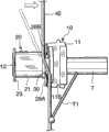
Fig. 1 is the stereogram that the stator of embodiments of the present invention is used electromagnet.
Fig. 2 is the sectional elevation of the stator core of embodiments of the present invention.
Fig. 3 is the stereogram of the first cutting unit of the formation insulator of embodiments of the present invention.
Fig. 4 is the stereogram of observing the first cutting unit from different directions.
Fig. 5 is the amplification plan view of the flange major part of the first cutting unit.
Fig. 6 consists of the stereogram of the second cutting unit of insulator, embodiments of the present invention with the first cutting unit.
Fig. 7 is the stereogram of observing the second cutting unit from different directions.
Fig. 8 is embodiments of the present invention, be wound on the stereogram of the coil on the insulator.
Fig. 9 is the stator core of embodiments of the present invention and the vertical view of anchor clamps.
The vertical view of stator core, anchor clamps and wire rod that Figure 10 describes to phase I of the spiral technique of insulator embodiments of the present invention, coil.
The vertical view of stator core, anchor clamps and wire rod that Figure 11 describes to the second stage of the spiral technique of insulator embodiments of the present invention, coil.
The vertical view of stator core, anchor clamps and wire rod that Figure 12 describes to phase III of the spiral technique of insulator embodiments of the present invention, coil.
The vertical view of stator core, anchor clamps and wire rod that Figure 13 describes to the quadravalence section of the spiral technique of insulator embodiments of the present invention, coil.
The vertical view of stator core, anchor clamps and wire rod that Figure 14 describes to the five-stage of the spiral technique of insulator embodiments of the present invention, coil.
The vertical view of stator core, anchor clamps and wire rod that Figure 15 describes to the 6th stage of the spiral technique of insulator embodiments of the present invention, coil.
The vertical view of stator core, anchor clamps and wire rod that Figure 16 describes to the 7th stage of the spiral technique of insulator embodiments of the present invention, coil.
The vertical view of stator core, anchor clamps and wire rod that Figure 17 describes to the 8th stage of the spiral technique of insulator embodiments of the present invention, coil.
The vertical view of stator core, anchor clamps and wire rod that Figure 18 describes to the 9th stage of the spiral technique of insulator embodiments of the present invention, coil.
Figure 19 is the flange major part that describes of the situation to the second stage of the spiral technique of coil and the amplification plan view of wire rod.
Figure 20 is the flange major part that describes of the situation to the second stage of the spiral technique of coil and the amplification plan view of wire rod.
Figure 21 be the second stage of the spiral technique of coil when finishing the flange major part and the amplification plan view of wire rod.
Figure 22 A-Figure 22 C is that the coiling to coil begins and vertical view, front view and the end view of the flange that the treatment situation that finishes of reeling describes.
Figure 23 be expression top embodiments of the present invention, coil and terminal with collect the stereogram of distribution with the stator major part of the connection status of bus ring (bus ring).
Figure 24 is expression and the stereogram of collection distribution with the stator major part of the relevant variation of bus ring.
Figure 25 be illustrated in do not adopt comparative example of the present invention stator with the wire rod that carries out in the electromagnet to the insulator of the introducing technology of breach and the stereogram of wire rod.
Figure 26 be illustrated in do not adopt comparative example of the present invention stator with the wire rod that carries out in the electromagnet to the insulator of the introducing technology of breach and the vertical view of wire rod.
Figure 27 is the insulator of the state when being illustrated in the stator that do not adopt comparative example of the present invention and finishing to the introducing technology of breach with the wire rod that carries out in the electromagnet and the stereogram of wire rod.
Embodiment
With reference to Figure 23, in motor, generator, stator 1 is the general name of a plurality of electromagnet 2, its drive for the rotor to equipped with permanent magnetism iron so that this rotor and be configured in rotor around.
In motor, electromagnet is because being with magnetic and rotor being rotated around central axis to coil electricity.In generator, centered by central axis, carry out relative the rotation by rotor with stator 1, electromagnet makes generation current in the coil.
With reference to Fig. 2, stator 1 comprises around in the circumferential direction of the circle a plurality of stator cores 10 of combination of central axis.
Side in back of the body yoke 11 is formed with protuberance 11A.Side at the opposite side of carrying on the back yoke 11 is formed with recess 11B.Protuberance 11A is embedded in the recess 11B of adjacent stator core 10.
Periphery in scroll section 21, as shown in Figure 8, the wire rod 40 of coil is for example reeled in the mode of regular coiling.The coiling width of each winding layer of the flange 22 at the two ends of scroll section 21, the wire rod 40 of 23 limiting coils.In other words, flange 22,23 stops coil to stretch out to the outside of insulator 20.
Consider the 12 installing insulating bodies 20 to tooth section, insulator 20 is divided by the stacked direction along the electromagnetic steel plate of stator core 10, the first cutting unit 20A shown in Fig. 3,4 and the second cutting unit 20B shown in Fig. 6,7 consist of.
With reference to Fig. 1, the first cutting unit 20A and the second cutting unit 20B are incorporated into tooth section 12 with the form that the both sides from the central axial direction of stator 1 cover tooth section 12.
Therefore, the first cutting unit 20A comprises: the element 21A of scroll section, and it has the cross section of U font; Flange component 22A, it is formed at an end of backrest yoke 11 sides of the element 21A of scroll section; And flange component 23A, it is formed at an end of the side opposite with back of the body yoke 11 of the element 21A of scroll section.
Similarly, the second cutting unit 20B comprises: the element 21B of scroll section, and it has the cross section of U font; Flange component 22B, it is formed at an end of backrest yoke 11 sides of the element 21B of scroll section; And flange component 23B, it is formed at an end of the side opposite with back of the body yoke 11 of the element 21B of scroll section.
In addition, about cutting apart of insulator 20, except above segmenting structure, for example, also can along with the direction of the stacked direction quadrature of the electromagnetic steel plate of stator core 10, be that the circumferencial direction of stator core 10 is cut apart.And, also can be divided at the arbitrarily split position of the periphery of being located at tooth section 12 3 to 4 elements.
The first cutting unit 20A and the second cutting unit 20B are made of the second flange 23 of the end of the scroll section 21 of the drum that covers tooth section, first flange 22 of end of backrest yoke 11 sides of being located at scroll section 21 and a side opposite with back of the body yoke 11 of being located at scroll section 21 under bonding state.
With reference to Fig. 3 and Fig. 4, the element 21A of scroll section of the first cutting unit 20A on a side of the closure of stator core 10, be formed with two 24A of fillet section, 24B along winding direction.The element 21A of scroll section on another side of the link direction of stator core 10, be formed with the single 24C of fillet section along winding direction.In the footpath of stator 1 upwards, the formation position of the 24C of fillet section is equivalent between the formation position of the formation position of the 24A of fillet section and the 24B of fillet section.The element 21A of scroll section on the central axial direction of stator 1 with the bottom surface 26 of the end contact of tooth section 12 on, along a plurality of parallel groove 26A of radially being formed with of stator 1.
The connecting portion that is connected with the second cutting unit 20B at the element 21A of scroll section, flange component 22A and flange component 23A is formed with thin-walled fitting portion 25A.Thin-walled fitting portion 25A is that the face towards the top ends 122 of tooth section 12 by the face of facing mutually with back of the body yoke 11 of the face of facing mutually with tooth section 12 that makes the element 21A of scroll section, flange component 22A and flange component 23A retreats respectively specific length and forms.
Be fixed with snap-latch piece 26B at flange component 22A, this snap-latch piece 26B gives prominence to predetermined distance mutually continuously and to the radial outside of stator 1 with the bottom surface 26 of the element 21A of scroll section.As shown in Figure 1, snap-latch piece 26B contacts with an end face on the central axial direction of stator 1 of back of the body yoke 11, thus stator 1 axially on stator core 10 and insulator 20 are positioned.
Be formed with the breach 27 of rectangle at flange component 22A, this breach 27 is for the coiling beginning of the wire rod 40 of the coil on the periphery that will be wound on scroll section 21 and the coiling latter end is taken out to the first flange 22 from scroll section 21 the outside.Breach 27 is formed on the outstanding position of the central axial direction to stator 1 from stator iron core 10 of flange component 22A.
By forming breach 27, be formed with the first position 28A and the second position 28B that is positioned at across breach 27 side opposite with the first position 28A of the side that is positioned at breach 27 at flange component 22A.
With reference to Fig. 5, the first position 28A of breach 27, flange component 22A and the second position 28B all are located on the central axial direction of stator 1 than snap-latch piece 26B on scroll section 21 position far away.
Be formed with towards breach 27 and to the outstanding coiling of the footpath outward direction of stator 1 at the first position 28A and begin locator protrusions 30.On the first position 28A, also be formed with the first fastening groove 31 across beginning locator protrusions 30 and the breach 27 opposite sides of reeling.Also be formed with guide surface 29 on the first position 28A, it is used for making wire rod 40 to guide to breach 27 by reeling between beginning locator protrusions 30, the first fastening groove 31 and this three of snap-latch piece 26B.
With reference to Figure 22 B, in order wire rod 40 to be guided swimmingly wire rod 40 during from the lateral of the first flange 22 scroll section 21 guiding via breach 27, and guide surface 29 is formed the step that the base with respect to breach 27 tilts.When the spiral to scroll section 21 finished, the beginning locator protrusions 30 of reeling made the coiling beginning bending of wire rod 40 and positions and fastening.The first fastening groove 31 has the function of the coiling beginning of the self-align position displacement in coiling beginning that stops wire rod 40 and fastening wire rod 40.
Referring again to Fig. 5, be formed with towards breach 27 and to the outstanding coiling termination locator protrusions 33 of the footpath outward direction of stator 1 at the second position 28B.On the second position 28B, also be formed with the second fastening groove 34 across reel stopping locator protrusions 33 and breach 27 opposite sides.On the termination locator protrusions 33 of reeling, be formed with breach 35 at the position relative with fastening sheet 26B.
With reference to Figure 22 B and 22C, when the spiral to scroll section 21 finished, reeling stopped the coiling dwell section bending that locator protrusions 33 makes wire rod 40, thereby positions and fastening.The breach 35 that being formed at reels stops on the locator protrusions 33 prevents the lax of wire rod 40 by wire rod 40 being held in case of bending.And the second fastening groove 34 has the effect of the coiling dwell section of the self-align position displacement of coiling dwell section that stops wire rod 40 and fastening wire rod 40.
Referring again to Fig. 5, the first position 28A stator 1 axially on to set than the second position 28B from scroll section 21 outstanding outstanding length L 1 long from the outstanding outstanding length L 2 of scroll section 21 in the same direction.
By setting like this, as shown in figure 11, wire rod 40, is easily being carried out making wire rod 40 to the action of scroll section 21 lateral bends take the first position 28A as fulcrum during from the lateral of the first flange 22 scroll section 21 guiding via breach 27.
And the bight 30A towards breach 27 of preferred the first position 28A forms square.In addition, bight 30A reels to begin the bight of locator protrusions 30.And the bight 33A towards breach 27 at preferred the second position forms circle.In addition, bight 33A reels to stop the bight of locator protrusions 33.By such shape that bight 30A and 33A are set for, easily carry out making wire rod 40 to the action of scroll section 21 lateral bends take the first position 28A as fulcrum.
Referring again to Fig. 5, the degree of depth of the first fastening groove 31 is set deeplyer than the degree of depth of the second fastening groove 34, so that the base of the base of the first fastening groove 31 and the second fastening groove 34 is positioned at roughly on the same line.Thus, the fastening of wire rod 40 remains equal in the top of the first fastening groove 31 and the fastening of wire rod 40 in the distance apart from stator core 10 of the end of the second fastening groove 34.Top by making like this wire rod 40 and terminal fastening be in the distance that distance stator core 10 equates, the wire rod 40 that easily carries out coil is to fixing with the terminal 51 of bus ring 50 and terminal 53 of aftermentioned collection distribution.
With reference to Fig. 6 and Fig. 7, on the side of the element 21B of scroll section of the second cutting unit 20B, be provided with two 24A of fillet section, 24B along winding direction, on another side relative with side of the element 21B of scroll section, be provided with a 24C of fillet section along winding direction.
The element 21B of scroll section on a side of the link direction of stator core 10, be formed with for the 24A of fillet section, the 24B of the element 21A of scroll the section respectively consecutive fillet 24A of section, 24B.The element 21B of scroll section on another side of the link direction of stator core 10, be formed with for the consecutive fillet 24C of section of the 24C of fillet section of the element 21A of scroll section.
The connecting portion with the first cutting unit 20A at the second cutting unit 20B is formed with thin-walled fitting portion 25B.Thin-walled fitting portion 25B retreats respectively specific length by each face towards the spiral of coil that makes the element 21B of scroll section, flange component 22B and flange component 23B to form.
Under the state with the first cutting unit 20A and the second cutting unit 20B combination, thin-walled fitting portion 25A and thin-walled fitting portion 25B are overlapping, as shown in Figure 1 the scroll section 21 of being integrally formed, the first flange 22 and the second flange 23.
Coil is to carry out with Fig. 9-technique shown in Figure 180 under the state that as shown in Figure 1 insulator 20 is installed on stator core 10 to the spiral of insulator.Fig. 8 represents the state that spiral finishes.In addition, Fig. 9-Figure 18 is the vertical view of observing spiral technique from the top, wherein Fig. 9-Figure 13, Figure 16 and Figure 17 represent recess 11B towards the state of horizontal direction, Figure 14,15 and Figure 18 represent 20 rotations of stator core 10 and insulator roughly 90 degree and recess 11B state up.
With reference to Fig. 9, coil carries out under following state to the spiral of insulator 20, that is, at the stacked direction of the electromagnetic steel plate of stator core 10, in other words the central axial direction of stator 1 utilizes coil spiral anchor clamps T to control the state of the back of the body yoke 11 of stator core 10.Coil spiral anchor clamps T is driven in rotation the device driving and rotates.Follow the rotation of coil spiral anchor clamps T, stator core 10 and insulator 20 be integratedly rotation also.Coil spiral anchor clamps T comprises wire rod handle part T1.
With reference to Figure 10, wire rod handle part T1 is used for keeping utilizing the wire rod feedway from the end of the wire rod 40 of the top of figure supply.Wire rod handle part T1 keeps constant relative position with respect to stator core 10 and insulator 20.Wire rod handle part T1 and coil spiral anchor clamps T rotate with respect to the wire rod feedway of inactive state integratedly, thereby wire rod 40 are wound in the scroll section 21 of insulator 20.In addition, the wire rod feedway is correspondingly supplied with wire rod 40 by wire guide part and wire rod 40 that the central axial direction in scroll section 21 moves back and forth to the winding position of scroll section 21.
At drive coil spiral anchor clamps T so that its rotation and before wire rod 40 is wound in scroll section 21, controlled the wire rod 40 of supplying with from the wire rod feedway by wire rod handle part T1.At this moment, adjust the wire guide part so that wire rod 40 be positioned at back of the body yoke 11 the top, be wire rod 40 is positioned at the first flange 22 in the central axial direction of scroll section 21 the outside.
With reference to Figure 11, make the wire guide part from the direction of arrow of this state in the figure, be that the top orientation of tooth section 12 moves.The wire rod 40 that the end is controlled by wire rod handle part T1 begins locator protrusions 30 supportings by the coiling of the first position 28A that is formed at the first flange 22, and the beginning locator protrusions 30 of certainly reeling is guided to breach 27 to scroll section 21 lateral bends.
Here, as shown in Figure 5, the first position 28A sets longlyer than the outstanding length L 2 of giving prominence to from scroll section 21 of the second position 28B from scroll section 21 outstanding outstanding length L 1.
With reference to Figure 19,20, should outstanding length L 1 by setting, L2, utilizing the wire guide part to make wire rod 40 21 when crooked, can avoid wire rod 40 and the second position 28B interference as fulcrum to scroll section take the beginning locator protrusions 30 of reeling.
And, owing to being to make wire rod 40 bendings utilizing wire guide part and wire rod grasping device T1 wire rod 40 to be applied under the state of tension force, even therefore wire rod 40 has crooked tendency, also can be reliably via breach 27 with wire rod 40 guiding to scroll section 21.
With reference to Figure 25 and Figure 26, the identical situation of outstanding length of giving prominence to from scroll section 21 of the first position 28A and the second position 28B of the first flange 22 is described.In this situation, even want to make wire rod 40 bendings take the first position 28A as fulcrum, wire rod 40 also can be interfered with the second position 28B.
Therefore, tilt with respect to the first flange 22 like that as shown in figure 26 by the bearing of trend that makes in advance wire rod 40, wire rod 40 is guided to breach 27.Wire rod 40 is limited to the narrow and small zone of the arrow institute double team among the figure in this situation for the position range that can select by breach 27.Therefore, be difficult to efficiently to breach 27 guiding wire rods 40.The wire rod 40 that the narrow and small situation of the position range that wire rod 40 can be selected also causes having the tendency of reeling is difficult to guiding.
Referring again to Figure 20, by as this stator 1, setting the outstanding length L 1 of giving prominence to from scroll section 21 of the first position 28A longer than the outstanding length L 2 of giving prominence to from scroll section 21 of the second position 28B, can make wire rod 40 crooked as fulcrum to horizontal direction take the first position 28A, via the top of the second position 28B wire rod 40 be guided to scroll section 21.
With reference to Figure 21, if under this state drive coil spiral anchor clamps T and make its rotation, beginning then guides to wire rod 40 inboard of breach 27 reliably to scroll section 21 wound skein products 40.Like this, interfere by avoiding reliably wire rod 40 and the first flange 22, can locate accurately the winding start position of spiral.
With reference to Figure 27, in the inboard of the first flange 22, namely carry on the back yoke 11 sides when having step H, the wire rod 40 that is directed to breach 27 is the amount suitable with step H from scroll section 21 is outstanding.On this part, be wound as the wire rod 40 of stratiform also from scroll section 21 hangs.Finally, the height of coil end uprises.
In this stator 1, be formed with for the guide surface 29 that between the first fastening groove 31, coiling beginning locator protrusions 30 and this three of fastening sheet 26B, guides wire rod 40 at the first position 28A.Even there is step H, also by forming like this guide surface 29, the wire rod 40 that arrives scroll section 21 via breach 27 is contacted reliably with the surface of scroll section 21.Therefore, can prevent that wire rod 40 is from scroll section 21 hangs.
With reference to Figure 12, via breach 27 wire rod 40 is being guided after scroll section 21, the wire guide part is moved along the direction of arrow among the figure and make the second position 28B butt of wire rod 40 and the first flange 22, thereby carry out wire rod 40 to location that the coiling of scroll section 21 begins.Under this state, if drive coil spiral anchor clamps T and make its rotation then is wound in scroll section 21 with wire rod 41.By making accordingly wire guide part and scroll section 21 mobile abreast with coiling, wire rod 40 gaplesss are wound in scroll section 21 with arranging.
With reference to Figure 13, by proceeding this spiral operation, make wire rod 40 arrive the second flange 23 to the coiling of scroll section 21.Afterwards, make wire guide part and scroll section 21 oppositely mobile abreast, and drive coil spiral anchor clamps T and make its rotation, then wound skein product 40 again on the layer of the wire rod 40 of having reeled.So, between the first flange 22 and the second flange 23, carry out the coiling of the wire rod 40 of multilayer.
With reference to Figure 14, when the spiral of the number of plies of regulation finished, near the position of rotation place that comes at wire rod 40 breach 27 of the first flange 22 stopped the rotation of coil spiral anchor clamps T.This is with to make coil spiral anchor clamps T be the position of rotation of the slightly postrotational stator core 10 in position of level from recess 11B suitable.
With reference to Figure 15, under this state, make the wire guide part shown in the arrow among the figure like that and scroll section 21 abreast to the outer side shifting of the first flange 22.Accompany therewith, finish the outside that is taken out to the first flange 22 to the wire rod 40 of scroll section 21 spirals via breach 27.
With reference to Figure 16, these state-driven coil spiral anchor clamps T makes its rotation roughly 90 when spending certainly, and wire rod 40 is sticked in the breach 35 that coiling on the second position 28B that is formed on the first flange 22 stops locator protrusions 33.
With reference to Figure 17, wire rod 40 is sticked in after the breach 35, make the wire guide part again like that parallel with scroll section 21 shown in the arrow among the figure and move to the direction opposite with Figure 15.
With reference to Figure 18, further drive coil spiral anchor clamps T makes roughly 90 degree and stopping of its rotation.Thus, wire rod 40 fastenings of breach 27 have been passed through in the breach 35 of the termination locator protrusions 33 of reeling.Under this state, wire rod 40 is cut off between breach 35 and wire guide part.And the coiling beginning of wire rod 40 begins to be cut off between locator protrusions 30 and the wire rod grasping device T1 at the coiling of the first position 28A.Its result, as shown in Figure 8, wire rod 40 finishes to the coiling of scroll section 21.
Under this state, shown in Figure 22 A, the coiling dwell section of wire rod 40 is by breach 27, and the breach 35 that stops locator protrusions 33 via reeling is walked around to reel and stopped locator protrusions 33, extends upward.Shown in Figure 22 C, make this part via fastening groove 34 to scroll section 21 lateral bends.The coiling dwell section of wire rod 40 easily produces lax under the rebound effect of the coil that the elasticity because of wire rod 40 causes.In this stator 1, after the coiling dwell section of wire rod 40 is sticked in breach 35, walks around and reel stopping locator protrusions 33, further from fastening groove 34 to scroll section 21 lateral bends, thereby seek the anti-loosening of wire rod 40.
Shown in Figure 22 B, the coiling beginning of the wire rod 40 after the cut-out is along guide surface 29 to oblique extension.Coiling take the first position 28A of the first flange begins locator protrusions 30 as guiding piece makes this part crooked upward, further makes this part to scroll section 21 lateral bends via fastening groove 31 like that shown in Figure 22 C.Be difficult to produce lax although the coiling beginning of wire rod 40 is pressed by the spiral on upper strata, but by walking around like this after the beginning locator protrusions 30 of reeling from fastening groove 31 to scroll section 21 lateral bends, also can seek anti-loosening for the coiling beginning of wire rod 40.
As mentioned above, by insulator 20 is installed on stator core 10, and at the spiral of the scroll section 21 enterprising line circles of insulator 20, thereby consist of an electromagnet 2.The electromagnet 2 of the specified quantity that consists of like this is inserted into by the protuberance 11A that will carry on the back yoke 11 among the recess 11B of adjacent back of the body yoke 11 and is linked successively, thus the stator 1 of formation ring-type.
With reference to Figure 23, the stator 1 of ring-type is configured in the collection distribution of the shell of being located at motor or generator with the inboard of bus ring 50.The collection distribution alternately is provided with for the terminal 51 of the top 40A of the coil that connects each electromagnet 2 terminal 52 with the terminal 40B of the coil that is connected connecting each electromagnet 2 with bus ring 50.
In each electromagnet 2, the top 40A of coil walks around the beginning locator protrusions 30 of reeling, thereby determines extracting position.The terminal 40B of coil walks around to reel and stops locator protrusions 33, thereby determines extracting position.By in advance setting the beginning locator protrusions 30 and reel and stop the position of locator protrusions 33 of reeling with terminal 51 and terminal 52 in the consistent mode in the interval that makes progress in week, be connected with coil being connected of the top 40A that can be respectively carries out coil with beeline and terminal 51 being connected of terminal 40B and terminal 52.
And in stator 1, the top 40A of coil and terminal 40B remain on respectively the inboard of fastening groove 31 and fastening groove 34.Fastening groove 31 and fastening groove 34 have following effect: when the stator 1 when a plurality of electromagnet 2 being assembled into the stator 1 of ring-type, after will assembling is configured in the collection distribution with bus ring 50 inboard, stops the dislocation of the top 40A of coil and terminal 40B and remain in the position location.Therefore, the first fastening groove 31 be connected that fastening groove 34 makes top 40A and to be connected the connection operation that 40B is connected with terminal to terminal 51 easier.
But the location of wire rod 40 itself can be undertaken by reel beginning locator protrusions 30 and the termination locator protrusions 33 of reeling.Therefore, as shown in the figure, also can on the first flange 22, only be formed with breach 27, coiling beginning locator protrusions 30 and the termination locator protrusions 33 of reeling, and omit the first fastening groove 31 and the second fastening groove 34.
With reference to Figure 24, illustrate about collection distribution other structures with bus ring 50.
This collection distribution comprises that with bus ring 50 terminal 53 and terminal 54 replace terminal 51 and the terminal 52 among Figure 23.
So consist of terminal 53 and terminal 54, then when the stator 1 with ring-type inserts with the inboard of bus ring 50 to the collection distribution, have the possibility of the top 40A of coil and terminal 40B and terminal 53,54 interferences.Stator 1 with ring-type under following state just can prevent this interference to collecting the inboard insertion of distribution with bus ring 50, namely, form the first fastening groove 31 and the second fastening grooves 34 at the first flange 22, at the top 40A that makes coil and terminal 40B via the first fastening groove 31 and the second fastening groove 34 and under the state of the center position bending of stator 1.
In this situation, after the assigned position of stator 1 insertion collection distribution with the inboard of bus ring 50, by with coil via the first fastening groove 31 and the second fastening groove 34 and to the center position bending of stator 1 top 40A and terminal 40B return to linear state from case of bending respectively, can easily import among gap 53A and the gap 54A.
About above explanation, quoted take Japanese Patent Application 2010-65753 number the content of March 23 as the applying date in 2010 and be incorporated in the above explanation.
Above, by several specific embodiment the present invention has been described, but the present invention is not limited to each above-mentioned embodiment.To those skilled in the art, can in the protection range of claims, implement various modifications or change to above-described embodiment.
For example, the wire rod 40 that insulator 20 is carried out spiral can be that the square-section also can be circular cross-section.Breach 27 is not limited to rectangle, also can be the breach 27 of U word shape or V word shape for example.
Utilizability on the industry
Used the stator of electromagnet of the present invention by use, manufacturing process's rationalization, raising workmanship for motor, generator can obtain desirable effect.The exclusive character that embodiments of the invention comprise or characteristics are as claimed in claim.
Claims (9)
1. a stator is with electromagnet (2), wherein,
This stator comprising with electromagnet (2):
Stator core (10), it is by back of the body yoke (11) and certainly carry on the back outstanding tooth section (12) formation of yoke (11);
Insulator (20), it is installed on tooth section (tooth) (12);
Coil, it is wound in insulator (20) and forms,
Insulator (20) comprising:
Scroll section (21), it is multilaminate coiled for coil;
The first flange (22), the end that it is formed at scroll section (21) is formed with the breach (27) that the wire rod (40) for coil passes;
The second flange (23), it is formed at the other end of scroll section (21),
And the outstanding length of giving prominence to from scroll section (21) of the first flange (22) is set as different length in the both sides of breach (27).
2. stator according to claim 1 is with electromagnet (2), wherein,
The first flange (22) is formed on the end of backrest yoke (11) side of scroll section (21), the wire rod of coil (40) is directed to scroll section (21) from the outside of the first flange (22) via breach (27), after scroll section (21) is wound into multilayer, be taken out to the outside of the first flange (22) via breach (27).
3. stator according to claim 2 is with electromagnet (2), wherein,
The first flange (22) comprises first position (28A) of the side that is positioned at breach (27) and is positioned at across second position (28B) of breach (a 27) side opposite with the first position (28A), long from the outstanding outstanding length of scroll section (21) from outstanding outstanding Length Ratio the second position (28B) of scroll section (21) of the first position (28A).
4. stator according to claim 3 is with electromagnet (2), wherein,
The first position (28A) has the square bight (30A) that faces breach (27), and the second position (28B) that faces has the bight (33A) of the circle that faces breach (27).
According to claim 3 or 4 described stators with electromagnet (2), wherein,
The second position (28B) has near breach (27) and reel to stop locator protrusions (33), and it is outstanding that this coilings stops locator protrusions (33) yoke (11) that supports or opposes, for the coiling final position of positioning wire (40).
6. stator according to claim 5 is with electromagnet (2), wherein,
The first position (28A) has the beginning locator protrusions (30) of reeling near breach (27), this coilings beginning locator protrusions (30) yoke (11) that supports or opposes is outstanding, for the winding start position of positioning wire (40).
7. stator according to claim 6 is with electromagnet (2), wherein,
The first position (28A) be formed with the first fastening groove (31) for the top of fastening wire rod (40) across reel stopping locator protrusions (a 30) side opposite with breach (27), be formed with the second fastening groove (34) for the end of fastening wire rod (40) in locator protrusions (33) side opposite with breach (27) that begin across reeling of the second position (28B).
8. stator according to claim 7 is with electromagnet (2), wherein,
The degree of depth of the depth ratio second fastening groove (34) of the first fastening groove (31) is dark.
9. a stator is with the manufacture method of electromagnet (2), wherein,
Insulator (20) is installed on the tooth section (12) of stator core (10), this insulator (20) comprising: scroll section (21); The first flange (22), it is formed at an end of scroll section (21), is formed with the breach (27) that the wire rod (40) for coil passes at the first flange (22); The second flange (23), it is formed at the other end of scroll section (21), the outstanding length of giving prominence to from scroll section (21) of the first flange (22) is set as different length in the both sides of breach (27), this stator core (10) is by back of the body yoke (11) and certainly carry on the back outstanding tooth section (12) formation of yoke (11)
With the wire rod (40) of coil via breach (27) from the guided outside of the first flange (22) to scroll section (21), after scroll section (21) is wound into multilayer, take out to the outside of the first flange (22) via breach (27) from scroll section (21).
Applications Claiming Priority (3)
| Application Number | Priority Date | Filing Date | Title |
|---|---|---|---|
| JP2010065753A JP5636710B2 (en) | 2010-03-23 | 2010-03-23 | Insulator for rotating electrical machine and method for manufacturing stator winding structure |
| JP2010-065753 | 2010-03-23 | ||
| PCT/JP2011/054909 WO2011118357A1 (en) | 2010-03-23 | 2011-03-03 | Electromagnet for stator and method of manufacturing electromagnet for stator |
Publications (2)
| Publication Number | Publication Date |
|---|---|
| CN102934331A true CN102934331A (en) | 2013-02-13 |
| CN102934331B CN102934331B (en) | 2015-02-04 |
Family
ID=44672925
Family Applications (1)
| Application Number | Title | Priority Date | Filing Date |
|---|---|---|---|
| CN201180012738.4A Active CN102934331B (en) | 2010-03-23 | 2011-03-03 | Electromagnet for stator and method of manufacturing electromagnet for stator |
Country Status (5)
| Country | Link |
|---|---|
| US (1) | US9203274B2 (en) |
| EP (1) | EP2551993B1 (en) |
| JP (1) | JP5636710B2 (en) |
| CN (1) | CN102934331B (en) |
| WO (1) | WO2011118357A1 (en) |
Cited By (6)
| Publication number | Priority date | Publication date | Assignee | Title |
|---|---|---|---|---|
| CN105746757A (en) * | 2016-03-25 | 2016-07-13 | 梧州市中茗茶业有限公司 | Tea fermentation barrel |
| CN103580316B (en) * | 2012-08-03 | 2017-06-30 | 三星电子株式会社 | Motor and the washing machine with the motor |
| CN107947420A (en) * | 2017-11-28 | 2018-04-20 | 广东美的环境电器制造有限公司 | Insulation frame, Insulating frame and motor stator for motor and preparation method thereof |
| CN110323854A (en) * | 2018-03-30 | 2019-10-11 | 株式会社丰田自动织机 | The manufacturing method of the stator of the stator of rotating electric machine, rotating electric machine and rotating electric machine |
| CN111052554A (en) * | 2017-08-29 | 2020-04-21 | 株式会社美姿把 | Insulator for motor and brushless motor |
| CN112821589A (en) * | 2019-11-15 | 2021-05-18 | 日本电产株式会社 | Stator and motor |
Families Citing this family (24)
| Publication number | Priority date | Publication date | Assignee | Title |
|---|---|---|---|---|
| JP6033573B2 (en) * | 2012-04-27 | 2016-11-30 | 株式会社ニフコ | Insulator for stator |
| FR2992493B1 (en) * | 2012-06-20 | 2015-07-10 | Valeo Equip Electr Moteur | COIL INSULATION WITH A FINALLY WALL FORMING AN ELECTRICALLY INSULATING WALL AND ASSOCIATED ELECTRIC MACHINE ELEMENT |
| KR20140003674A (en) * | 2012-06-22 | 2014-01-10 | 엘지이노텍 주식회사 | Motor |
| DE102012224012A1 (en) * | 2012-12-20 | 2014-06-26 | Tyco Electronics Belgium Ec Bvba | Spool for mounting on a magnetic core, reluctance resolver and method of manufacture |
| CN103928999B (en) * | 2013-01-10 | 2017-08-11 | 广东美的环境电器制造有限公司 | The bobbin winder bracket and its method for winding of stator, block-stator motor |
| DE102013204759A1 (en) | 2013-03-19 | 2014-09-25 | Robert Bosch Gmbh | Tooth segment for assembling a stator or rotor of an electric machine and method for the production of such |
| JP5928904B2 (en) * | 2013-08-06 | 2016-06-01 | 株式会社安川電機 | Insulator, stator assembly, rotating electric machine, and wiring board |
| JP5959757B2 (en) | 2013-10-30 | 2016-08-02 | 三菱電機株式会社 | Electric motor, compressor provided with the same, and method for manufacturing electric motor |
| JP6225804B2 (en) * | 2014-04-07 | 2017-11-08 | 株式会社安川電機 | Bobbins and rotating electrical machines |
| JP6801946B2 (en) * | 2015-01-20 | 2020-12-16 | トヨタ自動車株式会社 | Insulator formation method |
| US10038348B2 (en) * | 2015-08-12 | 2018-07-31 | Regal Beloit America, Inc. | Liner, stator assembly and associated method |
| EP3582371A4 (en) * | 2017-02-13 | 2020-12-02 | LG Innotek Co., Ltd. | Stator and motor comprising same |
| JP6700211B2 (en) * | 2017-03-15 | 2020-05-27 | アイチエレック株式会社 | Stator and electric motor |
| JP6656474B2 (en) * | 2017-06-02 | 2020-03-04 | デンソートリム株式会社 | Rotating electric machine |
| JP7314361B2 (en) * | 2017-06-14 | 2023-07-25 | 株式会社マキタ | Electric tool |
| CN110892610B (en) * | 2017-06-14 | 2022-06-14 | 株式会社牧田 | Electric tool |
| CN111095740B (en) | 2017-09-20 | 2022-07-29 | 松下知识产权经营株式会社 | Insulator, stator including the same, and motor including the same |
| US11277048B2 (en) | 2017-09-20 | 2022-03-15 | Panasonic Intellectual Property Management Co., Ltd. | Insulator, and stator and motor comprising same |
| US11355984B2 (en) | 2017-09-20 | 2022-06-07 | Panasonic Intellectual Property Management Co., Ltd. | Insulator, and stator and motor comprising same |
| WO2019146451A1 (en) * | 2018-01-24 | 2019-08-01 | パナソニックIpマネジメント株式会社 | Insulator, stator provided with same, and motor |
| GB2577546B (en) * | 2018-09-28 | 2023-05-24 | Dyson Technology Ltd | A stator core assembly |
| JP7247720B2 (en) * | 2019-04-03 | 2023-03-29 | 株式会社プロテリアル | Radial gap type rotary electric machine and method for manufacturing radial gap type rotary electric machine |
| KR102317047B1 (en) * | 2019-07-25 | 2021-10-25 | 엘지전자 주식회사 | Stator and Motor having the same |
| JP2022178706A (en) * | 2021-05-20 | 2022-12-02 | 株式会社デンソー | Insulator, stator, and manufacturing method for the stator |
Citations (7)
| Publication number | Priority date | Publication date | Assignee | Title |
|---|---|---|---|---|
| JPS6322707U (en) * | 1986-07-29 | 1988-02-15 | ||
| JP2002284446A (en) * | 2001-03-23 | 2002-10-03 | Moric Co Ltd | Winding bobbin for electric device |
| CN1893225A (en) * | 2005-06-30 | 2007-01-10 | 富士通将军股份有限公司 | Electric motor |
| US20080136286A1 (en) * | 2006-12-12 | 2008-06-12 | Hiromichi Hiramatsu | Concentrated winding coil and method of manufacturing same |
| JP2008178223A (en) * | 2007-01-18 | 2008-07-31 | Toyota Motor Corp | Insulator bobbin and assembly method therefor |
| JP2008236854A (en) * | 2007-03-19 | 2008-10-02 | Nissan Motor Co Ltd | Insulating insulator, structure of stator and manufacturing method |
| CN101322199A (en) * | 2005-11-30 | 2008-12-10 | 丰田自动车株式会社 | Cassette coil and rotating electrical machine having the cassette coil |
Family Cites Families (18)
| Publication number | Priority date | Publication date | Assignee | Title |
|---|---|---|---|---|
| JP2002176753A (en) * | 2000-12-07 | 2002-06-21 | Matsushita Electric Ind Co Ltd | Stator for motor and manufacturing method thereof |
| JP3718473B2 (en) * | 2002-01-08 | 2005-11-24 | 草津電機株式会社 | Electric motor |
| DE20204507U1 (en) * | 2002-03-21 | 2002-06-06 | Grundfos As | Coil carrier as an insulating material for an electrical coil |
| JP3980402B2 (en) * | 2002-05-13 | 2007-09-26 | 本田技研工業株式会社 | Rotating electric machine |
| ES2412181T3 (en) * | 2003-01-10 | 2013-07-10 | Askoll Holding S.R.L. | Synchronous electric motor with a permanent magnet rotor and improved support reels for circulation pumps of heating and air conditioning systems |
| US7026739B2 (en) * | 2003-05-23 | 2006-04-11 | Honda Motor Co., Ltd | Stator and insulating bobbin and a manufacturing method of the stator |
| DE10345631A1 (en) * | 2003-09-29 | 2005-05-04 | Siemens Ag | Electric machine with carrier device with measuring system |
| JP4483480B2 (en) * | 2004-08-27 | 2010-06-16 | アイシン精機株式会社 | Stator and motor |
| US20060071569A1 (en) * | 2004-10-04 | 2006-04-06 | Stewart William P | Stator end caps and methods for positioning the lead and exit ends of the stator windings |
| US7095150B2 (en) * | 2004-10-21 | 2006-08-22 | Shop Vac Corporation | Apparatus for securing a bobbin of a reluctance machine |
| DE102006021903A1 (en) * | 2006-05-11 | 2007-11-22 | Zf Friedrichshafen Ag | Winding body for receiving winding of electrical conductor, has winding area formed by winding carrier and legs that are connected with winding carrier, where winding carrier has profile for guiding electrical conductor |
| JP2008072801A (en) * | 2006-09-13 | 2008-03-27 | Mitsuba Corp | Coil device, stator, and motor |
| JP4791387B2 (en) * | 2007-02-21 | 2011-10-12 | 三菱電機株式会社 | Armature |
| DE102007035531A1 (en) * | 2007-07-28 | 2009-01-29 | Zf Friedrichshafen Ag | Winding arrangement for electrical machine, has coil windings arranged at teeth and comprise inner region representing wedge surface, where one of windings is arranged at teeth by winding form |
| JP4967909B2 (en) * | 2007-08-02 | 2012-07-04 | 日産自動車株式会社 | Insulator, stator and stator manufacturing method |
| JP5315743B2 (en) * | 2008-03-26 | 2013-10-16 | アイシン精機株式会社 | Electric rotary motor |
| JP5153433B2 (en) * | 2008-04-22 | 2013-02-27 | 三菱電機株式会社 | Electric motor |
| JP4868187B2 (en) * | 2009-01-16 | 2012-02-01 | 株式会社富士通ゼネラル | Electric motor |
-
2010
- 2010-03-23 JP JP2010065753A patent/JP5636710B2/en active Active
-
2011
- 2011-03-03 EP EP11759165.1A patent/EP2551993B1/en active Active
- 2011-03-03 US US13/635,995 patent/US9203274B2/en active Active
- 2011-03-03 WO PCT/JP2011/054909 patent/WO2011118357A1/en active Application Filing
- 2011-03-03 CN CN201180012738.4A patent/CN102934331B/en active Active
Patent Citations (7)
| Publication number | Priority date | Publication date | Assignee | Title |
|---|---|---|---|---|
| JPS6322707U (en) * | 1986-07-29 | 1988-02-15 | ||
| JP2002284446A (en) * | 2001-03-23 | 2002-10-03 | Moric Co Ltd | Winding bobbin for electric device |
| CN1893225A (en) * | 2005-06-30 | 2007-01-10 | 富士通将军股份有限公司 | Electric motor |
| CN101322199A (en) * | 2005-11-30 | 2008-12-10 | 丰田自动车株式会社 | Cassette coil and rotating electrical machine having the cassette coil |
| US20080136286A1 (en) * | 2006-12-12 | 2008-06-12 | Hiromichi Hiramatsu | Concentrated winding coil and method of manufacturing same |
| JP2008178223A (en) * | 2007-01-18 | 2008-07-31 | Toyota Motor Corp | Insulator bobbin and assembly method therefor |
| JP2008236854A (en) * | 2007-03-19 | 2008-10-02 | Nissan Motor Co Ltd | Insulating insulator, structure of stator and manufacturing method |
Cited By (8)
| Publication number | Priority date | Publication date | Assignee | Title |
|---|---|---|---|---|
| CN103580316B (en) * | 2012-08-03 | 2017-06-30 | 三星电子株式会社 | Motor and the washing machine with the motor |
| CN105746757A (en) * | 2016-03-25 | 2016-07-13 | 梧州市中茗茶业有限公司 | Tea fermentation barrel |
| CN111052554A (en) * | 2017-08-29 | 2020-04-21 | 株式会社美姿把 | Insulator for motor and brushless motor |
| CN111052554B (en) * | 2017-08-29 | 2022-11-08 | 株式会社美姿把 | Insulator for motor and brushless motor |
| CN107947420A (en) * | 2017-11-28 | 2018-04-20 | 广东美的环境电器制造有限公司 | Insulation frame, Insulating frame and motor stator for motor and preparation method thereof |
| CN107947420B (en) * | 2017-11-28 | 2020-05-05 | 广东美的环境电器制造有限公司 | Insulating frame for motor, insulating frame, motor stator and manufacturing method of motor stator |
| CN110323854A (en) * | 2018-03-30 | 2019-10-11 | 株式会社丰田自动织机 | The manufacturing method of the stator of the stator of rotating electric machine, rotating electric machine and rotating electric machine |
| CN112821589A (en) * | 2019-11-15 | 2021-05-18 | 日本电产株式会社 | Stator and motor |
Also Published As
| Publication number | Publication date |
|---|---|
| EP2551993A4 (en) | 2017-10-11 |
| US20130009512A1 (en) | 2013-01-10 |
| US9203274B2 (en) | 2015-12-01 |
| EP2551993B1 (en) | 2018-06-06 |
| JP5636710B2 (en) | 2014-12-10 |
| WO2011118357A1 (en) | 2011-09-29 |
| EP2551993A1 (en) | 2013-01-30 |
| JP2011200059A (en) | 2011-10-06 |
| CN102934331B (en) | 2015-02-04 |
Similar Documents
| Publication | Publication Date | Title |
|---|---|---|
| CN102934331A (en) | Electromagnet for stator and method of manufacturing electromagnet for stator | |
| CN101411040B (en) | Stator of a rotary electric machine having secured core slot insulators | |
| KR100323313B1 (en) | Stator of vehicle alternator | |
| CN101873023B (en) | Armature | |
| EP1555735B1 (en) | Rotor for dynamo-electric machine | |
| CN103532280B (en) | Interconnector for stator of an electric machine and associated electric machine stator | |
| JP4600580B2 (en) | Stator coil manufacturing method | |
| JP5877035B2 (en) | Flat wire winding structure | |
| CN102067418B (en) | Method for manufacturing stator coil | |
| US8291577B2 (en) | Apparatus for loading stator windings into a stator core | |
| US20080010812A1 (en) | Method of forming single-layer coils | |
| KR20200085122A (en) | Stator assembly for hairpin winding | |
| CN102549892A (en) | Production method and production apparatus for stator | |
| EP3057206A1 (en) | Lubricant channel on a stator winding support | |
| US20180152071A1 (en) | Stator | |
| CN103840576A (en) | Wire guide for use in an electric machine | |
| CN102257706B (en) | Device for manufacturing stator | |
| US6533209B2 (en) | Dynamo-electric machine stator winder methods and apparatus with loop-forming wire pullers | |
| EP1251628A2 (en) | Stator pole winding method and apparatus | |
| USRE28831E (en) | Electric motor winding | |
| CN107925321B (en) | Method for manufacturing armature | |
| CN104283340A (en) | Stator for motor | |
| US20230155463A1 (en) | Method for external winding of esp motor using a split core stator | |
| EP2725590B1 (en) | Coil wire support element, manufacturing method thereof, and inductive power transfer coupler incorporating same | |
| KR102538593B1 (en) | Stator assembly for hairpin winding motor |
Legal Events
| Date | Code | Title | Description |
|---|---|---|---|
| C06 | Publication | ||
| PB01 | Publication | ||
| C10 | Entry into substantive examination | ||
| SE01 | Entry into force of request for substantive examination | ||
| C14 | Grant of patent or utility model | ||
| GR01 | Patent grant |