EP2551688A1 - Device, method and system for determining battery degradation - Google Patents
Device, method and system for determining battery degradation Download PDFInfo
- Publication number
- EP2551688A1 EP2551688A1 EP12177703A EP12177703A EP2551688A1 EP 2551688 A1 EP2551688 A1 EP 2551688A1 EP 12177703 A EP12177703 A EP 12177703A EP 12177703 A EP12177703 A EP 12177703A EP 2551688 A1 EP2551688 A1 EP 2551688A1
- Authority
- EP
- European Patent Office
- Prior art keywords
- battery
- fitting
- degradation
- equivalent circuit
- values
- Prior art date
- Legal status (The legal status is an assumption and is not a legal conclusion. Google has not performed a legal analysis and makes no representation as to the accuracy of the status listed.)
- Granted
Links
Images


Classifications
-
- G—PHYSICS
- G01—MEASURING; TESTING
- G01R—MEASURING ELECTRIC VARIABLES; MEASURING MAGNETIC VARIABLES
- G01R31/00—Arrangements for testing electric properties; Arrangements for locating electric faults; Arrangements for electrical testing characterised by what is being tested not provided for elsewhere
- G01R31/36—Arrangements for testing, measuring or monitoring the electrical condition of accumulators or electric batteries, e.g. capacity or state of charge [SoC]
- G01R31/392—Determining battery ageing or deterioration, e.g. state of health
-
- H—ELECTRICITY
- H01—ELECTRIC ELEMENTS
- H01M—PROCESSES OR MEANS, e.g. BATTERIES, FOR THE DIRECT CONVERSION OF CHEMICAL ENERGY INTO ELECTRICAL ENERGY
- H01M10/00—Secondary cells; Manufacture thereof
- H01M10/42—Methods or arrangements for servicing or maintenance of secondary cells or secondary half-cells
- H01M10/48—Accumulators combined with arrangements for measuring, testing or indicating the condition of cells, e.g. the level or density of the electrolyte
-
- B—PERFORMING OPERATIONS; TRANSPORTING
- B60—VEHICLES IN GENERAL
- B60R—VEHICLES, VEHICLE FITTINGS, OR VEHICLE PARTS, NOT OTHERWISE PROVIDED FOR
- B60R16/00—Electric or fluid circuits specially adapted for vehicles and not otherwise provided for; Arrangement of elements of electric or fluid circuits specially adapted for vehicles and not otherwise provided for
- B60R16/02—Electric or fluid circuits specially adapted for vehicles and not otherwise provided for; Arrangement of elements of electric or fluid circuits specially adapted for vehicles and not otherwise provided for electric constitutive elements
- B60R16/04—Arrangement of batteries
-
- H—ELECTRICITY
- H02—GENERATION; CONVERSION OR DISTRIBUTION OF ELECTRIC POWER
- H02J—CIRCUIT ARRANGEMENTS OR SYSTEMS FOR SUPPLYING OR DISTRIBUTING ELECTRIC POWER; SYSTEMS FOR STORING ELECTRIC ENERGY
- H02J7/00—Circuit arrangements for charging or depolarising batteries or for supplying loads from batteries
- H02J7/0047—Circuit arrangements for charging or depolarising batteries or for supplying loads from batteries with monitoring or indicating devices or circuits
- H02J7/005—Detection of state of health [SOH]
-
- G—PHYSICS
- G01—MEASURING; TESTING
- G01R—MEASURING ELECTRIC VARIABLES; MEASURING MAGNETIC VARIABLES
- G01R31/00—Arrangements for testing electric properties; Arrangements for locating electric faults; Arrangements for electrical testing characterised by what is being tested not provided for elsewhere
- G01R31/36—Arrangements for testing, measuring or monitoring the electrical condition of accumulators or electric batteries, e.g. capacity or state of charge [SoC]
- G01R31/367—Software therefor, e.g. for battery testing using modelling or look-up tables
-
- G—PHYSICS
- G01—MEASURING; TESTING
- G01R—MEASURING ELECTRIC VARIABLES; MEASURING MAGNETIC VARIABLES
- G01R31/00—Arrangements for testing electric properties; Arrangements for locating electric faults; Arrangements for electrical testing characterised by what is being tested not provided for elsewhere
- G01R31/36—Arrangements for testing, measuring or monitoring the electrical condition of accumulators or electric batteries, e.g. capacity or state of charge [SoC]
- G01R31/389—Measuring internal impedance, internal conductance or related variables
-
- Y—GENERAL TAGGING OF NEW TECHNOLOGICAL DEVELOPMENTS; GENERAL TAGGING OF CROSS-SECTIONAL TECHNOLOGIES SPANNING OVER SEVERAL SECTIONS OF THE IPC; TECHNICAL SUBJECTS COVERED BY FORMER USPC CROSS-REFERENCE ART COLLECTIONS [XRACs] AND DIGESTS
- Y02—TECHNOLOGIES OR APPLICATIONS FOR MITIGATION OR ADAPTATION AGAINST CLIMATE CHANGE
- Y02E—REDUCTION OF GREENHOUSE GAS [GHG] EMISSIONS, RELATED TO ENERGY GENERATION, TRANSMISSION OR DISTRIBUTION
- Y02E60/00—Enabling technologies; Technologies with a potential or indirect contribution to GHG emissions mitigation
- Y02E60/10—Energy storage using batteries
Abstract
Description
- The present disclosure relates to a battery degradation determination device, a battery degradation determination method and a battery degradation determination system, which determine a degree of battery degradation based on AC impedance measurement data for a battery.
- A battery such as a secondary battery or a fuel cell is degraded depending upon a number of recharging cycles, a usage environment, a storage condition, and the like and becomes unserviceable when the service life thereof is eventually exceeded. For this reason, various methods for determining a degree of battery degradation have previously been proposed, and for example, a method has been known in which the degree of degradation is determined based on a circuit constant obtained by fitting AC impedance measurement data of the battery to an equivalent circuit model of the battery.
- As an equivalent circuit model, an RC two-stage model has widely been used in which two stages of RC parallel circuit blocks are connected to a resistance R1 as shown in
Fig.9 . The unknown circuit constants in the RC parallel circuit block are R and C, the number of which is two per one stage, and it is possible to easily perform fitting because the number of unknown circuit constants in the RC two-stage model are not so large. - An AC impedance characteristic is typically represented by a Nyquist diagram as a complex impedance characteristic. As shown in
Fig. 10 , when the RC two-stage model is used as the equivalent circuit model, fitting error tends to be large for a battery with a deformed arc-shaped complex impedance characteristic. Here, inFig. 10 , a broken line represents an actually measured complex impedance characteristic, while a solid line represents a complex impedance characteristic based on circuit constants obtained by fitting to the RC two-stage model. - An actual battery rarely has a complex impedance characteristic represented by perfect semicircular shapes and has a deformed arc-shaped complex impedance characteristic as shown by the broken line in
Fig. 10 in many cases. For this reason, it cannot be said that a degradation determination result based on the circuit constants obtained by fitting to the RC two-stage model is always sufficiently appropriate. - [Patent Document 1] Japanese Unexamined Patent Application Publication No.
2004-241325 - Generally, fitting error can be reduced with respect to the deformed arc-shaped complex impedance characteristic with the use of an equivalent circuit in which three or more stages of RC parallel circuit blocks are connected. However, the number of unknown circuit constants to be fitted increases.
- In addition, it has been known that the use of one or more R and CPE (Constant Phase Element) parallel circuit blocks allows for reducing the fitting error with respect to the deformed arc-shaped AC impedance characteristic. Here, CPE is a non-linear element represented by impedance ZCPE as shown by [Equation 1] where P as a CPE index and T as a CPE constant are used as circuit constants.

- The fitting error can be reduced with respect to the deformed arc-shaped complex impedance characteristic as shown in
Fig. 12 by using an equivalent circuit model in which there are two stages of R and CPE parallel circuit blocks as shown inFig. 11 , for example. In addition, a broken line represents an actually measured complex impedance characteristic while a solid line represents a complex impedance characteristic based on the circuit constants obtained by fitting to the equivalent circuit model in which two stages of R and CPE parallel circuit blocks are connected inFig. 12 . - However, unknown circuit constants to be fitted in the R and CPE parallel circuit block are R, P, and T, the number of which is three per one stage, and the number of unknown circuit constants to be fitted is increased even in the two-stage model as compared with the RC two-stage model.
- If the number of unknown circuit constants to be fitted increases, fitting becomes complicated, and in some cases, it becomes impossible or difficult to determine a degree of battery degradation due to a plurality of obtained solutions. For this reason, a technique has been desired which reduces the fitting error without increasing the number of unknown circuit constants in the equivalent circuit model.
- One or more exemplary embodiments of the present invention provide a battery degradation determination device, a battery degradation determination method, and a battery degradation determination system, which reduces fitting error without increasing a number of unknown circuit constants in an equivalent circuit model to be used for determining a degree of battery degradation.
- A battery degradation determination device according to an exemplary embodiment of the invention, comprises:
- a fitting module configured to fit AC impedance measurement data into an equivalent circuit model including at least one circuit block in which a resistance and a constant phase element are connected in parallel, and to obtain circuit constants in the equivalent circuit model;
- a P-value saving module configured to save P values being index of the constant phase element obtained by fitting AC impedance measurement data of a reference battery to the equivalent circuit model; and
- a degradation determination module configured to perform degradation determination for a battery as a determination target based on circuit constants obtained by fitting AC impedance measurement data of the battery as a determination target to the equivalent circuit model with the use of the P values as fixed values, with reference to correlations between degrees of battery degradation and the circuit constants in the equivalent circuit model.
- The degradation determination module may be configured to determine that use of the battery as a determination target is not appropriate when fitting error by the obtained circuit constants is equal to or greater than a reference value.
- The battery degradation determination device may further comprises:
- a fitting initial value setting module configured to set initial values of the circuit constants prior to the fitting by the fitting module,
- wherein the fitting initial value setting module is configured to set the initial values with the use of a zero crossing point at which Zim=0 and elliptical approximation using an inflection point and zero of a frequency characteristic diagram of dZim/dZre when AC impedance measurement data is expressed as a Nyquist diagram.
- A battery degradation determination method according to an exemplary embodiment of the invention, comprises:
- saving P values being index of a constant phase element obtained by fitting AC impedance measurement data of a reference battery to an equivalent circuit model including at least one circuit block in which a resistance and the constant phase element are connected in parallel; and
- performing degradation determination for a battery as a determination target based on circuit constants obtained by fitting AC impedance measurement data of the battery as a determination target to the equivalent circuit model with the use of the P values as fixed values, with reference to database storing correlations between degrees of battery degradation and the circuit constants in the equivalent circuit model.
- The battery degradation determination method may further comprises:
- creating the database by recording correlations between a plurality of known degrees of degradation and circuit constants obtained by fitting AC impedance measurement data of a battery whose degree of degradation is known to the equivalent circuit model with the use of the P values as fixed values.
- According to the exemplary embodiments of the present invention, it is possible to provide a battery degradation determination device, a battery degradation determination method, and a battery degradation determination system, which reduces fitting error without increasing a number of unknown circuit constants in an equivalent circuit model to be used for determining a degree of battery degradation.
- The above and other aspects of the present invention will become more apparent from the following description of exemplary embodiments, taken in conjunction with the accompanying drawings of which:
-
Fig. 1 is a block diagram showing a configuration of a battery degradation determination system according to an embodiment. -
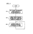
Fig. 2 is a flowchart showing an outline of a battery degradation determination operation of a battery degradation determination device. -
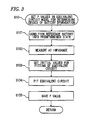
Fig. 3 is a flowchart showing the detailed procedure in the processing for setting the P values in an equivalent circuit model to be used for determining the degree of degradation of the battery. -
Fig. 4 is a diagram showing Nyquist diagram obtained as a result of measurement of the AC impedance of the reference battery. -
Fig. 5 is a diagram showing setting of a P2 initial value and a P3 initial value. -
Fig. 6 is a flowchart showing the detailed procedure in the processing for creating correlation data between circuit constants in the equivalent circuit model and the degree of degradation. -
Fig. 7 is a diagram showing a correlation example between the circuit constant and the amount of output degradation. -
Fig. 8 is a flowchart showing the detailed procedure in processing for determining the degree of degradation of a battery as a determination target. -
Fig. 9 is a diagram showing an example of a RC two-stage model. -
Fig. 10 is a diagram showing measured values and fitting result of the RC two-stage model. -
Fig. 11 is a diagram showing an equivalent circuit model in which there are two stages of R and CPE parallel circuit blocks. -
Fig. 12 is a diagram showing measured values and fitting result of the equivalent circuit model in which there are two stages of R and CPE parallel circuit blocks. -
Fig. 13 is a schematic diagram showing a hardware configuration of the battery degradation determination device according to the embodiment. - Description will be given of an embodiment of the present invention with reference to the drawings.
Fig. 1 is a block diagram showing a configuration of a battery degradation determination system according to an embodiment. As shown in the drawing, a batterydegradation determination system 10 includes a batterydegradation determination device 100, a circuit constant-degradationdegree correlation database 200, and an ACimpedance measurement device 300. The batterydegradation determination system 10 may be configured as a single device including the above components or as a set of respectively independent devices. Although the battery as a target of the degradation determination is preferably a secondary battery such as a lithium ion battery, the present invention can be applied to degradation determination of other batteries such as a fuel cell. Furthermore, the present invention can be applied to SOC (State Of Charge) determination for a battery. - According to this embodiment, an equivalent circuit model including one or more circuit blocks in each of which a resistance R and a CPE (Constant Phase Element) are connected in parallel is used for fitting. In so doing, fitting error is reduced with respect to a deformed arc-shaped complex impedance characteristic.
- Specifically, an equivalent circuit model is used in which a resistance R1, a circuit block in which a resistance R2 and CPE2 are in parallel, a circuit block in which a resistance R3 and CPE3 are in parallel, a CPE4, and a circuit block in which a resistance R5 and a coil L5 are connected to each other as shown in
Fig. 11 . However, the present invention is not limited to this equivalent circuit model, and any equivalent circuit model is applicable as long as one or more circuit blocks in which a resistance R and a CPE are in parallel are included. - The AC
impedance measurement apparatus 300 is an apparatus which measures AC impedance of abattery 400 as a measurement target and records a measurement result thereon, and includes an ACimpedance measurement module 310, an AC impedance measurementcondition setting module 320, and a measurementdata storage module 330. The ACimpedance measurement module 310 calculates AC impedance by applying AC voltage or AC current to thebattery 400 and measuring the current or the voltage based on a measurement condition received by the AC impedance measurementcondition setting module 320 from a user. The measurement is performed over a plurality of frequencies and the result thereof is stored as Nyquist diagram data, for example, on the measurementdata storage module 330 as a memory region. - However, a method of measuring AC impedance is not limited to that in the aforementioned example, and various methods can be used. For example, a voltage waveform or a current waveform in which a plurality of frequency signals are superimposed may be applied to measure the current waveform or the voltage waveform, and the voltage waveform and the current waveform may respectively be subjected to Discrete Fourier Transform (DFT) to obtain a ratio for each frequency component. In addition, separately obtained Nyquist diagram data may be stored on the measurement
data storage module 330 without measuring the AC impedance. - The circuit constant-degradation
degree correlation database 200 is a database which records a correlation between circuit constants as equivalent circuit parameters and a degree of battery degradation (capacity degradation, output degradation, and the like). It is possible to determine a degree of battery degradation by measuring the AC impedance of the battery as a target of the degradation determination, fitting the thus obtained complex impedance characteristic to the equivalent circuit model to obtain the circuit constants, and referring to the circuit constant-degradationdegree correlation database 200 based on the obtained circuit constants. - The battery
degradation determination device 100 can be configured with the use of an information processing apparatus such as a PC which operates based on computer programs. The batterydegradation determination device 100 includes acontroller 110, an input andoutput module 120, a fitting initialvalue setting module 130, afitting module 140, a P-value saving module 150, and adegradation determination module 160. - The
controller 110 controls battery degradation determination processing by causing each functional module in the batterydegradation determination device 100 to operate through a procedure that will be described later. The input andoutput module 120 controls inputting and outputting of data to and from the circuit constant-degradationdegree correlation database 200 and reading of data from the measurementdata storage module 330 in the ACimpedance measurement device 300. The input andoutput module 120 also receives operations and setting performed by the user, and outputs a result of battery degradation determination to a display device or the like which is not shown in the drawings. - The fitting initial
value setting module 130 sets initial values of circuit constants in the equivalent circuit model based on a predetermined algorithm from the Nyquist diagram data obtained from the measurementdata storage module 330. - The
fitting module 140 uses the initial values set by the fitting initialvalue setting module 130 to perform fitting of the circuit constants in the equivalent circuit model. As the fitting algorithm, various known algorithms can be employed. - The P-
value saving module 150 is a memory region which saves P values obtained in advance under a predetermined condition prior to the degradation determination processing for a battery as a determination target. - The
degradation determination module 160 determines a degree of battery degradation from the circuit constants obtained by fitting the complex impedance characteristic of the battery as a target of the degradation measurement to the equivalent circuit, with reference to the circuit constant-degradationdegree correlation database 200. The degree of degradation can be expressed by various manners using an amount of capacity degradation, an amount of output degradation, and the like. - Next, description will be given of a battery degradation determination operation of the battery
degradation determination device 100 according to this embodiment.Fig. 2 is a flowchart showing an outline of the battery degradation determination operation. - According to this embodiment, the P values in the equivalent circuit model for determining the degree of battery degradation are firstly set (S10). That is, the P values in the equivalent circuit model are set prior to the actual battery degradation determination, and the set P values are used as fixed values to perform fitting of the equivalent circuit model. In so doing, CPE constant T is the only unknown circuit constant in the CPE, and therefore, it is possible to reduce the number of unknown circuit constants even in the equivalent circuit model including R and CPE parallel circuit blocks to the same number as in the CR parallel circuit blocks. Accordingly, it is possible to reduce the fitting error without increasing the number of unknown circuit constants.
- Here, the pre-set P values are used to perform fitting of the battery as a target of the degradation determination since it has experimentally been verified that the P values can be regarded as constant values in a same type of battery regardless of a degree of degradation to an extent that the characteristic as a battery is not greatly damaged, an SOC, a temperature, and the like.
- Next, circuit constants of a battery whose degree of degradation is known are obtained by the fitting with the use of the set P values as fixed values, and correlation data between the circuit constants in the equivalent circuit model and the degree of degradation is created (S20). The correlation data for different degrees of degradation is created and recorded in the circuit constant-degradation
degree correlation database 200. - Thereafter, the degradation determination for the battery as a determination target can be repeatedly performed based on the set P values and the correlation data recorded in the circuit constant-degradation degree correlation database 200 (S30).
- Description will be given of a detailed procedure in such processing. First, a description will be given of the detailed procedure in the processing for setting the P values in the equivalent circuit model to be used for determining the degree of degradation of the battery (S10) with reference to a flowchart in
Fig. 3 . - In this processing, a battery as a reference for setting the P values is prepared and conditioned into a battery state allowing for obtaining complex impedance from which the P values can be specified without causing a plurality of solutions or a divergent solution (S101). The complex impedance characteristic from which the P values can be specified without causing a plurality of solutions or a divergent solution has a shape of a line which becomes wider in a direction of a low frequency area, for example, and is generally a characteristic with a shape of a line which becomes wider under conditions such as a predetermined degradation state, a low temperature, and a low SOC (State of Charge). Since the P values can be regarded to be constant even when such conditions are varied as described above, a battery state allowing for easy fitting can be arbitrarily set. On the contrary, fitting is divergent in some cases for a complex impedance characteristic with arcs in proximity, and therefore, a battery state accompanied by such a complex impedance characteristic is avoided.
- Then, the AC
impedance measurement device 300 is used to measure the AC impedance of the reference battery (S102). The obtained measurement data is stored as a Nyquist diagram on the measurementdata storage module 330. - Next, an initial value for fitting is set for the obtained Nyquist diagram of the reference battery with the use of the fitting initial value setting module 130 (S103). The initial value can be set based on the following algorithm, for example. In addition, it is assumed that the Nyquist diagram as shown in
Fig. 4 has been obtained as a result of measurement of the AC impedance of the reference battery. - In relation to an R1 initial value, Zre0 which is Zre at a zero crossing point of the Nyquist diagram is obtained, and Zre0 is regarded as an R1 initial value.
- In relation to a P2 initial value and a P3 initial value, a frequency characteristic of dZim(f)/DZre(f) as shown in
Fig. 5 is obtained, a point at which dZim(f)/DZre(f) becomes zero or an inflection point is searched in an order from a higher frequency, and a first frequency and a second frequency are regarded as f1 and f2, respectively. However, if an inflection point appears first, the frequency at the inflection point is used, and zero is ignored once. - Then, the P2 initial value is obtained from a ratio between dZim(f1) and DZre(f1)-Zre0 as shown by [Equation 2].

- Next, Zim at points where Zre becomes Zre(f2)-Zim(f2)×3/4, Zre(f2)-Zim(f2)/4, Zre(f2)+Zim(f2)/4, and Zre(f2)+Zim(f2)×3/4 is obtained. When there is no data point, linear interpolation may be performed.
- Based on the obtained four data points, an ellipse with a longer axis in parallel with a Zre direction is approximated by a known method. Then, the P3 initial value is obtained from [Equation 3] in which b represents a length of the longer axis of the obtained ellipse and a represents the shorter axis thereof.

- In addition, an R2 initial value is obtained as R2=(Zre(f1)-Zre0)×2, a T2 initial value is obtained as T2=1/[(2πf1)^P2×R2], an R3 initial value is obtained as R3=b, and a T3 initial value is obtained as T3=1/[(2πf2)^P3×R3]. It is a matter of course that another algorithm may be used to set an initial value of each circuit constant.
- Returning to the description of
Fig. 3 , when the initial values are set, thefitting module 140 performs fitting of the equivalent circuit model with the use of the set initial values (S104). Since the reference battery has been conditioned so as to obtain a Nyquist diagram with a shape which becomes wider in the direction of a low frequency area, it is possible to easily obtain each circuit constant by performing fitting with the use of a known algorithm. - Then, the P values (P2, P3) are stored on the P-
value saving module 150 among the circuit constants obtained by the fitting (S105), and processing for setting the P values in the equivalent circuit model for determining the degree of battery degradation (S10) is completed. - Next, description will be given of detailed procedure in the processing for creating correlation data between the circuit constants in the equivalent circuit model and the degree of degradation (S20) with reference to a flowchart in
Fig. 6 . - First, a battery whose degree of degradation such as capacity degradation and output degradation has been known is selected (S201). Then, the selected battery is conditioned so as to meet the impedance measurement condition for determining the degree of degradation (S202), and the AC impedance is measured with the use of the AC impedance measurement device 300 (S203). A predetermined temperature, a predetermined SOC, or the like can be set as the impedance measurement condition for determining the degree of degradation. The obtained measurement data is stored as a Nyquist diagram on the measurement
data storing module 330. - Next, initial values for fitting are set for the obtained Nyquist diagram of the battery with a known degree of degradation with the use of the fitting initial value setting module 130 (S204). The initial values can be set based on the same algorithm as that used in the aforementioned processing (S103). However, it is not necessary to calculate P initial values since the P values are fixed values.
- Then, the
fitting module 140 uses the P values saved in the P-value saving module 150 as fixed circuit constants and performs fitting of the equivalent circuit model with the use of the set initial values (S205). Since the P values are fixed circuit constants, the number of unknown circuit constants is the same as that in the RC two-stage model. Accordingly, it is possible to easily obtain each circuit constant by performing fitting with the use of the known algorithm. - The obtained circuit constants are associated with the known degree of battery degradation and registered as correlation data in the circuit constant-degradation degree correlation database 200 (S206).
- The above processing is repeatedly performed on batteries with different degrees of degradation (S207: No), and when the number of registered correlation data items is full (S207: Yes), the processing for creating the correlation data between the circuit constants in the equivalent circuit model and the degrees of degradation (S20) is completed.
Fig. 7 is a diagram showing a correlation example between the circuit constant R3 and the amount of output degradation. As shown in the drawing, it has been known that R in the equivalent circuit model becomes greater as a charge-discharge cycle is repeated. - Next, description will be given of detailed procedure in processing for determining the degree of degradation of a battery as a determination target (S30) with reference to a flowchart in
Fig. 8 . - First, a battery as a target of degradation determination is conditioned so as to meet the impedance measurement condition for determining the degree of degradation (S301). Specifcally, a temperature, an SOC, and the like are conditioned to the same levels as those in the processing for creating the correlation data between the circuit constants in the equivalent circuit model and the degrees of degradation (S20).
- Then, the AC impedance of the battery as a determination target is measured with the use of the AC impedance measurement device 300 (S302). The obtained measurement data is stored as a Nyquist diagram on the measurement
data storage module 330. - Next, initial values for fitting are set for the obtained Nyquist diagram of the battery as a determination target with the use of the fitting initial value setting module 130 (5303). The initial values can be set based on the same algorithm as that used in the aforementioned processing (S103). However, it is not necessary to calculate P initial values since the P values are fixed values.
- Then, the
fitting module 140 uses the P values saved in the P-value saving module 150 as fixed circuit constants and performs fitting of the equivalent circuit model with the use of the set initial values (S304). Since the P values are fixed circuit constants, the number of unknown circuit constants is the same as that in the RC two-stage model. Accordingly, it is possible to easily obtain each circuit constant by performing fitting with the use of the known algorithm. - Then, the
degradation determination module 160 determines a degree of degradation of the battery as a determination target based on the obtained circuit constants with reference to the circuit constant-degradation degree correlation database 200 (S305). A determination result is output to a display device, a printing device, or the like which is not shown in the drawings (S306), and the processing for determining the degree of degradation of the battery as a determination target (S30) is completed. - While fitting error can be reduced in this embodiment, the characteristic including the P values fluctuates and the fitting error becomes greater when the battery is in an unserviceable state after degradation.
- For this reason, the
degradation determination module 160 may obtain a square error between the complex impedance characteristic calculated with the use of the circuit constants obtained as a result of fitting and the complex impedance characteristic obtained as a result of measurement, and may output, via the input andoutput module 120, a determination result indicating that the use of the battery is not appropriate when the square error becomes equal to or greater than a pre-set reference value. - Hereinafter, the battery impedance measuring device according to the present embodiment will be described in relation to hardware components.
-
Fig. 13 is a schematic diagram showing a hardware configuration of the batterydegradation determination device 100 according to the present embodiment. As shown inFig. 13 , the batterydegradation determination device 100 includes aCPU 1, areader 2, amemory 3, astorage device 4, acommunication unit 5 and auser interface 6. The CPU 1 (for example, a processor) may serve as thecontroller 110, the input andoutput module 120, the fitting initialvalue setting module 130, thefitting module 140, the P-value saving module 150, and thedegradation determination module 160 shown inFig. 1 . - The
memory 3 may be any type of memory such as ROM, RAM or a flash memory. Thememory 3 may serve as a working memory of theCPU 1 when theCPU 1 executes a program. Thestorage device 4 is configured to store programs to be executed by theCPU 1 and/or data (for example, P values) generated by the respective components. Thestorage device 4 may be any type of storage device such as a hard disk drive (HDD) or solid state drive (SSD). A program which includes instructions for causing theCPU 1 to execute respective operations performed by the batterydegradation determination device 100 may be stored in thestorage device 4 or in a computer-readable medium such as a Blu-ray Disc (trademark), DVD, a CD, a floppy disc, a flash memory, or magneto-optical (MO) disc. Thereader 2 is configured to read the program stored in the above-computer readable medium into thememory 3. The program may be also downloaded from another device (for example, a server) on a network (for example, the Internet) through thecommunication unit 5. With this configuration shown inFig. 13 , theCPU 1 is configured to implement the respective operations performed by the batterydegradation determination device 100 according to the program read from thereader 2 or downloaded through thecommunication unit 5. - In the determination of a degree of degradation according to this embodiment, the fitting is performed with the use of an equivalent circuit model including circuit blocks, in each of which a register R and CPE are in parallel as described above, it is possible to reduce fitting error. Accordingly, appropriateness of a determination result can be enhanced. Furthermore, P values are fixed values among circuit constants in the CPE, and therefore, the number of unknown circuit constants to be fitted is the same as that in the RC model, which facilitates the fitting.
Claims (6)
- A battery degradation determination device comprising:a fitting module configured to fit AC impedance measurement data into an equivalent circuit model including at least one circuit block in which a resistance and a constant phase element are connected in parallel, and to obtain circuit constants in the equivalent circuit model;a P-value saving module configured to save P values being index of the constant phase element obtained by fitting AC impedance measurement data of a reference battery to the equivalent circuit model; anda degradation determination module configured to perform degradation determination for a battery as a determination target based on circuit constants obtained by fitting AC impedance measurement data of the battery as a determination target to the equivalent circuit model with the use of the P values as fixed values, with reference to correlations between degrees of battery degradation and the circuit constants in the equivalent circuit model.
- The battery degradation determination device according to Claim 1, wherein the degradation determination module is configured to determine that use of the battery as a determination target is not appropriate when fitting error by the obtained circuit constants is equal to or greater than a reference value.
- The battery degradation determination device according to Claim 1 or 2, further comprising:a fitting initial value setting module configured to set initial values of the circuit constants prior to the fitting by the fitting module,wherein the fitting initial value setting module is configured to set the initial values with the use of a zero crossing point at which Zim=0 and elliptical approximation using an inflection point and zero of a frequency characteristic diagram of dZim/dZre when AC impedance measurement data is expressed as a Nyquist diagram.
- A battery degradation determination method comprising:saving P values being index of a constant phase element obtained by fitting AC impedance measurement data of a reference battery to an equivalent circuit model including at least one circuit block in which a resistance and the constant phase element are connected in parallel; andperforming degradation determination for a battery as a determination target based on circuit constants obtained by fitting AC impedance measurement data of the battery as a determination target to the equivalent circuit model with the use of the P values as fixed values, with reference to database storing correlations between degrees of battery degradation and the circuit constants in the equivalent circuit model.
- The battery degradation determination method according to Claim 4, further comprising:creating the database by recording correlations between a plurality of known degrees of degradation and circuit constants obtained by fitting AC impedance measurement data of a battery whose degree of degradation is known to the equivalent circuit model with the use of the P values as fixed values.
- A battery degradation determination system comprising:an AC impedance measurement device configured to measure AC impedance of a battery;a battery degradation determination device comprising a fitting module configured to fit AC impedance measurement data obtained from the AC impedance measurement device into an equivalent circuit model including at least one circuit block in which a resistance and a constant phase element are connected in parallel, and to obtain circuit constants in the equivalent circuit model; anda database configured to store correlations between degrees of battery degradation and the circuit constants in the equivalent circuit model, whereinthe battery degradation determination device comprises
a P-value saving module configured to save P values being index of the constant phase element obtained by fitting AC impedance measurement data of a reference battery obtained from the AC impedance measurement device to the equivalent circuit model, and
a degradation determination module configured to perform degradation determination for a battery as a determination target based on circuit constants obtained by fitting AC impedance measurement data of the battery as a determination target obtained from the AC impedance measurement device to the equivalent circuit model with the use of the P values as fixed values, with reference to the database.
Applications Claiming Priority (1)
| Application Number | Priority Date | Filing Date | Title |
|---|---|---|---|
| JP2011161762A JP5278508B2 (en) | 2011-07-25 | 2011-07-25 | Battery degradation determination apparatus and method |
Publications (2)
| Publication Number | Publication Date |
|---|---|
| EP2551688A1 true EP2551688A1 (en) | 2013-01-30 |
| EP2551688B1 EP2551688B1 (en) | 2014-04-02 |
Family
ID=46640560
Family Applications (1)
| Application Number | Title | Priority Date | Filing Date |
|---|---|---|---|
| EP12177703.1A Not-in-force EP2551688B1 (en) | 2011-07-25 | 2012-07-24 | Device, method and system for determining battery degradation |
Country Status (5)
| Country | Link |
|---|---|
| US (1) | US9043176B2 (en) |
| EP (1) | EP2551688B1 (en) |
| JP (1) | JP5278508B2 (en) |
| KR (1) | KR101363195B1 (en) |
| CN (1) | CN102901928B (en) |
Cited By (4)
| Publication number | Priority date | Publication date | Assignee | Title |
|---|---|---|---|---|
| EP2821803A1 (en) * | 2013-07-02 | 2015-01-07 | Delphi Technologies, Inc. | Battery deterioration determining system |
| WO2017178016A1 (en) * | 2016-04-12 | 2017-10-19 | Zentrum für Sonnenenergie- und Wasserstoff-Forschung Baden-Württemberg Gemeinnützige Stiftung | Fuel cell forecast model based on an equivalent circuit diagram |
| WO2019217981A1 (en) * | 2018-05-14 | 2019-11-21 | Avl List Gmbh | Method for determining an equivalent circuit for an electrochemical cell |
| EP3993222A4 (en) * | 2019-06-27 | 2023-02-01 | Nuvoton Technology Corporation Japan | Battery management circuit, battery management device, and battery management network |
Families Citing this family (17)
| Publication number | Priority date | Publication date | Assignee | Title |
|---|---|---|---|---|
| JP6035028B2 (en) * | 2012-02-03 | 2016-11-30 | 横河電機株式会社 | Battery characteristics deriving device |
| US20150346285A1 (en) * | 2013-02-28 | 2015-12-03 | Hitachi Vehicle Energy, Ltd. | Device for Assessing Extent of Degradation of Secondary Battery |
| KR101610530B1 (en) | 2014-10-24 | 2016-04-07 | 현대자동차주식회사 | Method for measuring internal resistance of battery |
| CN106371018B (en) * | 2015-07-21 | 2019-05-24 | 上汽通用汽车有限公司 | Power cell of vehicle method for diagnosing faults and equipment based on battery terminal voltage estimation |
| CN105203969B (en) * | 2015-10-23 | 2018-04-13 | 南昌航空大学 | State-of-charge method of estimation based on modified RC battery models |
| JP6339618B2 (en) * | 2016-03-29 | 2018-06-06 | 古河電気工業株式会社 | Secondary battery degradation estimation device and secondary battery degradation estimation method |
| JP6647111B2 (en) | 2016-03-29 | 2020-02-14 | 古河電気工業株式会社 | Secondary battery deterioration estimating apparatus and secondary battery deterioration estimating method |
| US10761123B2 (en) * | 2016-10-31 | 2020-09-01 | City University Of Hong Kong | Method and an apparatus for use in an electric circuit |
| CN107329091B (en) * | 2017-07-13 | 2020-07-03 | 大唐恩智浦半导体有限公司 | Method, device and system for measuring internal temperature of battery |
| JP6881154B2 (en) * | 2017-08-23 | 2021-06-02 | トヨタ自動車株式会社 | Deterioration state estimation method for secondary batteries and secondary battery system |
| JP2019190905A (en) * | 2018-04-20 | 2019-10-31 | 株式会社Gsユアサ | Method and device for estimating state |
| JP2023522468A (en) * | 2020-04-24 | 2023-05-30 | 華為技術有限公司 | Battery detection method and device |
| JP2022029866A (en) * | 2020-08-05 | 2022-02-18 | 日置電機株式会社 | State measurement apparatus, state measurement method, and program |
| KR20230021963A (en) * | 2021-08-06 | 2023-02-14 | 주식회사 엘지에너지솔루션 | Electrode tap disconnection inspection device and disconnection inspection method of battery cell |
| JP7385696B2 (en) * | 2022-03-23 | 2023-11-22 | 本田技研工業株式会社 | Measuring device, measuring method, and program |
| JP7385698B2 (en) * | 2022-03-30 | 2023-11-22 | 本田技研工業株式会社 | Battery condition analysis system and battery condition analysis method |
| CN117214728B (en) * | 2023-11-09 | 2024-04-05 | 溧阳中科海钠科技有限责任公司 | Method and device for determining degradation degree of battery, electronic equipment and storage medium |
Citations (4)
| Publication number | Priority date | Publication date | Assignee | Title |
|---|---|---|---|---|
| US20020120906A1 (en) * | 2000-07-17 | 2002-08-29 | Lei Xia | Behavioral modeling and analysis of galvanic devices |
| US20030204328A1 (en) * | 2002-04-29 | 2003-10-30 | Joern Tinnemeyer | Multiple model systems and methods for testing electrochemical systems |
| JP2004241325A (en) | 2003-02-07 | 2004-08-26 | Espec Corp | Battery state diagnostic device and battery state diagnostic method |
| WO2005093447A2 (en) * | 2004-03-26 | 2005-10-06 | Eaton Power Quality Company | Method of testing an electrochemical device |
Family Cites Families (15)
| Publication number | Priority date | Publication date | Assignee | Title |
|---|---|---|---|---|
| JP3680573B2 (en) * | 1998-09-11 | 2005-08-10 | 株式会社村田製作所 | REACTANCE ELEMENT AND CIRCUIT MODULE USING THE REACTANCE ELEMENT |
| KR100462661B1 (en) * | 2002-07-02 | 2004-12-20 | 금호석유화학 주식회사 | Method for evaluating their capacities by calculating mathematically specific elements among resistance elements of equivalent circuit model fitted from impedance spectrum of secondary batteries |
| JP2005044697A (en) * | 2003-07-24 | 2005-02-17 | Nippon Oil Corp | Photoelectric conversion element |
| JP4038456B2 (en) * | 2003-08-25 | 2008-01-23 | 株式会社豊田中央研究所 | Battery characteristic detection method |
| JP4638195B2 (en) * | 2004-09-28 | 2011-02-23 | 富士重工業株式会社 | Battery degradation degree estimation device |
| JP2007108063A (en) * | 2005-10-14 | 2007-04-26 | Furukawa Electric Co Ltd:The | Method and device for determining secondary battery degradation, and power supply system |
| CN1975444A (en) * | 2005-11-28 | 2007-06-06 | 孙斌 | Accumulator cell internal resistance and degradation state on-line monitoring method and system |
| JP4946131B2 (en) * | 2006-03-29 | 2012-06-06 | 横河電機株式会社 | Apparatus and method for measuring characteristics of fuel cell |
| JP5088081B2 (en) * | 2007-10-12 | 2012-12-05 | 富士通株式会社 | Battery measuring method and battery manufacturing method |
| CN101639522B (en) * | 2008-08-01 | 2014-06-04 | 株式会社杰士汤浅国际 | Equipment for diagnosing degradable state of secondary battery |
| JP2010135290A (en) * | 2008-10-30 | 2010-06-17 | Toyota Motor Corp | Estimating method for estimating state of fuel cell and state estimating device |
| JP2010230469A (en) * | 2009-03-27 | 2010-10-14 | Calsonic Kansei Corp | Device and method for determining state of health of secondary battery |
| JP5633227B2 (en) * | 2009-10-14 | 2014-12-03 | ソニー株式会社 | Battery pack and battery pack deterioration detection method |
| JP2011122951A (en) * | 2009-12-11 | 2011-06-23 | Honda Motor Co Ltd | Charged state estimation device and deterioration state estimation device of secondary battery |
| JP5586219B2 (en) * | 2009-12-25 | 2014-09-10 | 株式会社東芝 | Diagnostic device, battery pack, and battery value index manufacturing method |
-
2011
- 2011-07-25 JP JP2011161762A patent/JP5278508B2/en not_active Expired - Fee Related
-
2012
- 2012-07-24 KR KR1020120080845A patent/KR101363195B1/en not_active IP Right Cessation
- 2012-07-24 EP EP12177703.1A patent/EP2551688B1/en not_active Not-in-force
- 2012-07-24 US US13/556,740 patent/US9043176B2/en not_active Expired - Fee Related
- 2012-07-25 CN CN201210260429.5A patent/CN102901928B/en not_active Expired - Fee Related
Patent Citations (4)
| Publication number | Priority date | Publication date | Assignee | Title |
|---|---|---|---|---|
| US20020120906A1 (en) * | 2000-07-17 | 2002-08-29 | Lei Xia | Behavioral modeling and analysis of galvanic devices |
| US20030204328A1 (en) * | 2002-04-29 | 2003-10-30 | Joern Tinnemeyer | Multiple model systems and methods for testing electrochemical systems |
| JP2004241325A (en) | 2003-02-07 | 2004-08-26 | Espec Corp | Battery state diagnostic device and battery state diagnostic method |
| WO2005093447A2 (en) * | 2004-03-26 | 2005-10-06 | Eaton Power Quality Company | Method of testing an electrochemical device |
Cited By (5)
| Publication number | Priority date | Publication date | Assignee | Title |
|---|---|---|---|---|
| EP2821803A1 (en) * | 2013-07-02 | 2015-01-07 | Delphi Technologies, Inc. | Battery deterioration determining system |
| WO2017178016A1 (en) * | 2016-04-12 | 2017-10-19 | Zentrum für Sonnenenergie- und Wasserstoff-Forschung Baden-Württemberg Gemeinnützige Stiftung | Fuel cell forecast model based on an equivalent circuit diagram |
| WO2019217981A1 (en) * | 2018-05-14 | 2019-11-21 | Avl List Gmbh | Method for determining an equivalent circuit for an electrochemical cell |
| EP3993222A4 (en) * | 2019-06-27 | 2023-02-01 | Nuvoton Technology Corporation Japan | Battery management circuit, battery management device, and battery management network |
| US11933854B2 (en) | 2019-06-27 | 2024-03-19 | Nuvoton Technology Corporation Japan | Battery management circuit, battery management system, and battery management network |
Also Published As
| Publication number | Publication date |
|---|---|
| US9043176B2 (en) | 2015-05-26 |
| KR20130012569A (en) | 2013-02-04 |
| JP5278508B2 (en) | 2013-09-04 |
| EP2551688B1 (en) | 2014-04-02 |
| CN102901928A (en) | 2013-01-30 |
| US20130030736A1 (en) | 2013-01-31 |
| JP2013026114A (en) | 2013-02-04 |
| KR101363195B1 (en) | 2014-02-12 |
| CN102901928B (en) | 2015-02-18 |
Similar Documents
| Publication | Publication Date | Title |
|---|---|---|
| EP2551688B1 (en) | Device, method and system for determining battery degradation | |
| JP6130275B2 (en) | Estimation apparatus and estimation method | |
| CN110146816B (en) | Method, device and equipment for determining remaining charging time of battery and storage medium | |
| Song et al. | The sequential algorithm for combined state of charge and state of health estimation of lithium-ion battery based on active current injection | |
| US20220374568A1 (en) | Simulation of a Battery | |
| Rothenberger et al. | Genetic optimization and experimental validation of a test cycle that maximizes parameter identifiability for a Li-ion equivalent-circuit battery model | |
| JP6615011B2 (en) | Battery management system, battery system and hybrid vehicle control system | |
| JP6488105B2 (en) | Storage battery evaluation apparatus and method | |
| JP5875037B2 (en) | Battery state prediction system, method and program | |
| KR20180056238A (en) | Battery charging method, battery charging information generating method and battery charging apparatus | |
| JP6200359B2 (en) | Secondary battery internal temperature estimation device and secondary battery internal temperature estimation method | |
| JP6253137B2 (en) | Battery state estimation device for secondary battery | |
| US10054645B2 (en) | Deterioration determination method, deterioration determination device, and storage medium | |
| JP6171897B2 (en) | Approximation function creation program, approximation function creation method, approximation function creation device, and charging rate estimation program | |
| JP6330605B2 (en) | Estimation program, estimation method, and estimation apparatus | |
| KR101777334B1 (en) | Apparatus and method for estimating SOH of battery | |
| KR20170134193A (en) | Method for estimating state of charge of battery and apparatus for impelmeing the method | |
| EP3736585A1 (en) | Method and device for predicting peak power of battery | |
| JP6161133B2 (en) | Data extraction apparatus, data extraction method, and data extraction program | |
| JP6421411B2 (en) | Estimation program for estimating battery charging rate, estimation method for estimating battery charging rate, and estimation device for estimating battery charging rate | |
| WO2017002953A1 (en) | Data extracting device, data extracting method, and data extracting program | |
| WO2015160745A2 (en) | Performance tracking of an electrical energy storage system | |
| CN111665443A (en) | Fitting method and device of battery performance formula, storage medium and computer equipment | |
| CN112906176B (en) | Health prediction method and system of battery equivalent circuit model | |
| KR20230028017A (en) | A model-based state-of-charge estimation device for lithium-ion batteries that is robust to time-varying load current situations and method thereof |
Legal Events
| Date | Code | Title | Description |
|---|---|---|---|
| PUAI | Public reference made under article 153(3) epc to a published international application that has entered the european phase |
Free format text: ORIGINAL CODE: 0009012 |
|
| AK | Designated contracting states |
Kind code of ref document: A1 Designated state(s): AL AT BE BG CH CY CZ DE DK EE ES FI FR GB GR HR HU IE IS IT LI LT LU LV MC MK MT NL NO PL PT RO RS SE SI SK SM TR |
|
| AX | Request for extension of the european patent |
Extension state: BA ME |
|
| 17P | Request for examination filed |
Effective date: 20130703 |
|
| RBV | Designated contracting states (corrected) |
Designated state(s): AL AT BE BG CH CY CZ DE DK EE ES FI FR GB GR HR HU IE IS IT LI LT LU LV MC MK MT NL NO PL PT RO RS SE SI SK SM TR |
|
| RIC1 | Information provided on ipc code assigned before grant |
Ipc: G01R 31/36 20060101AFI20130826BHEP |
|
| GRAP | Despatch of communication of intention to grant a patent |
Free format text: ORIGINAL CODE: EPIDOSNIGR1 |
|
| INTG | Intention to grant announced |
Effective date: 20131104 |
|
| GRAS | Grant fee paid |
Free format text: ORIGINAL CODE: EPIDOSNIGR3 |
|
| GRAA | (expected) grant |
Free format text: ORIGINAL CODE: 0009210 |
|
| AK | Designated contracting states |
Kind code of ref document: B1 Designated state(s): AL AT BE BG CH CY CZ DE DK EE ES FI FR GB GR HR HU IE IS IT LI LT LU LV MC MK MT NL NO PL PT RO RS SE SI SK SM TR |
|
| REG | Reference to a national code |
Ref country code: GB Ref legal event code: FG4D |
|
| REG | Reference to a national code |
Ref country code: AT Ref legal event code: REF Ref document number: 660432 Country of ref document: AT Kind code of ref document: T Effective date: 20140415 Ref country code: CH Ref legal event code: EP |
|
| REG | Reference to a national code |
Ref country code: IE Ref legal event code: FG4D |
|
| REG | Reference to a national code |
Ref country code: DE Ref legal event code: R096 Ref document number: 602012001275 Country of ref document: DE Effective date: 20140508 |
|
| REG | Reference to a national code |
Ref country code: AT Ref legal event code: MK05 Ref document number: 660432 Country of ref document: AT Kind code of ref document: T Effective date: 20140402 |
|
| REG | Reference to a national code |
Ref country code: NL Ref legal event code: VDEP Effective date: 20140402 |
|
| REG | Reference to a national code |
Ref country code: LT Ref legal event code: MG4D |
|
| PG25 | Lapsed in a contracting state [announced via postgrant information from national office to epo] |
Ref country code: IS Free format text: LAPSE BECAUSE OF FAILURE TO SUBMIT A TRANSLATION OF THE DESCRIPTION OR TO PAY THE FEE WITHIN THE PRESCRIBED TIME-LIMIT Effective date: 20140802 Ref country code: LT Free format text: LAPSE BECAUSE OF FAILURE TO SUBMIT A TRANSLATION OF THE DESCRIPTION OR TO PAY THE FEE WITHIN THE PRESCRIBED TIME-LIMIT Effective date: 20140402 Ref country code: BG Free format text: LAPSE BECAUSE OF FAILURE TO SUBMIT A TRANSLATION OF THE DESCRIPTION OR TO PAY THE FEE WITHIN THE PRESCRIBED TIME-LIMIT Effective date: 20140702 Ref country code: CZ Free format text: LAPSE BECAUSE OF FAILURE TO SUBMIT A TRANSLATION OF THE DESCRIPTION OR TO PAY THE FEE WITHIN THE PRESCRIBED TIME-LIMIT Effective date: 20140402 Ref country code: GR Free format text: LAPSE BECAUSE OF FAILURE TO SUBMIT A TRANSLATION OF THE DESCRIPTION OR TO PAY THE FEE WITHIN THE PRESCRIBED TIME-LIMIT Effective date: 20140703 Ref country code: NL Free format text: LAPSE BECAUSE OF FAILURE TO SUBMIT A TRANSLATION OF THE DESCRIPTION OR TO PAY THE FEE WITHIN THE PRESCRIBED TIME-LIMIT Effective date: 20140402 Ref country code: NO Free format text: LAPSE BECAUSE OF FAILURE TO SUBMIT A TRANSLATION OF THE DESCRIPTION OR TO PAY THE FEE WITHIN THE PRESCRIBED TIME-LIMIT Effective date: 20140702 Ref country code: FI Free format text: LAPSE BECAUSE OF FAILURE TO SUBMIT A TRANSLATION OF THE DESCRIPTION OR TO PAY THE FEE WITHIN THE PRESCRIBED TIME-LIMIT Effective date: 20140402 Ref country code: CY Free format text: LAPSE BECAUSE OF FAILURE TO SUBMIT A TRANSLATION OF THE DESCRIPTION OR TO PAY THE FEE WITHIN THE PRESCRIBED TIME-LIMIT Effective date: 20140402 |
|
| PG25 | Lapsed in a contracting state [announced via postgrant information from national office to epo] |
Ref country code: LV Free format text: LAPSE BECAUSE OF FAILURE TO SUBMIT A TRANSLATION OF THE DESCRIPTION OR TO PAY THE FEE WITHIN THE PRESCRIBED TIME-LIMIT Effective date: 20140402 Ref country code: PL Free format text: LAPSE BECAUSE OF FAILURE TO SUBMIT A TRANSLATION OF THE DESCRIPTION OR TO PAY THE FEE WITHIN THE PRESCRIBED TIME-LIMIT Effective date: 20140402 Ref country code: SE Free format text: LAPSE BECAUSE OF FAILURE TO SUBMIT A TRANSLATION OF THE DESCRIPTION OR TO PAY THE FEE WITHIN THE PRESCRIBED TIME-LIMIT Effective date: 20140402 Ref country code: AT Free format text: LAPSE BECAUSE OF FAILURE TO SUBMIT A TRANSLATION OF THE DESCRIPTION OR TO PAY THE FEE WITHIN THE PRESCRIBED TIME-LIMIT Effective date: 20140402 Ref country code: RS Free format text: LAPSE BECAUSE OF FAILURE TO SUBMIT A TRANSLATION OF THE DESCRIPTION OR TO PAY THE FEE WITHIN THE PRESCRIBED TIME-LIMIT Effective date: 20140402 Ref country code: HR Free format text: LAPSE BECAUSE OF FAILURE TO SUBMIT A TRANSLATION OF THE DESCRIPTION OR TO PAY THE FEE WITHIN THE PRESCRIBED TIME-LIMIT Effective date: 20140402 Ref country code: ES Free format text: LAPSE BECAUSE OF FAILURE TO SUBMIT A TRANSLATION OF THE DESCRIPTION OR TO PAY THE FEE WITHIN THE PRESCRIBED TIME-LIMIT Effective date: 20140402 |
|
| PG25 | Lapsed in a contracting state [announced via postgrant information from national office to epo] |
Ref country code: PT Free format text: LAPSE BECAUSE OF FAILURE TO SUBMIT A TRANSLATION OF THE DESCRIPTION OR TO PAY THE FEE WITHIN THE PRESCRIBED TIME-LIMIT Effective date: 20140804 |
|
| REG | Reference to a national code |
Ref country code: DE Ref legal event code: R097 Ref document number: 602012001275 Country of ref document: DE |
|
| PG25 | Lapsed in a contracting state [announced via postgrant information from national office to epo] |
Ref country code: DK Free format text: LAPSE BECAUSE OF FAILURE TO SUBMIT A TRANSLATION OF THE DESCRIPTION OR TO PAY THE FEE WITHIN THE PRESCRIBED TIME-LIMIT Effective date: 20140402 Ref country code: EE Free format text: LAPSE BECAUSE OF FAILURE TO SUBMIT A TRANSLATION OF THE DESCRIPTION OR TO PAY THE FEE WITHIN THE PRESCRIBED TIME-LIMIT Effective date: 20140402 Ref country code: BE Free format text: LAPSE BECAUSE OF FAILURE TO SUBMIT A TRANSLATION OF THE DESCRIPTION OR TO PAY THE FEE WITHIN THE PRESCRIBED TIME-LIMIT Effective date: 20140402 Ref country code: SK Free format text: LAPSE BECAUSE OF FAILURE TO SUBMIT A TRANSLATION OF THE DESCRIPTION OR TO PAY THE FEE WITHIN THE PRESCRIBED TIME-LIMIT Effective date: 20140402 Ref country code: RO Free format text: LAPSE BECAUSE OF FAILURE TO SUBMIT A TRANSLATION OF THE DESCRIPTION OR TO PAY THE FEE WITHIN THE PRESCRIBED TIME-LIMIT Effective date: 20140402 |
|
| PLBE | No opposition filed within time limit |
Free format text: ORIGINAL CODE: 0009261 |
|
| STAA | Information on the status of an ep patent application or granted ep patent |
Free format text: STATUS: NO OPPOSITION FILED WITHIN TIME LIMIT |
|
| PG25 | Lapsed in a contracting state [announced via postgrant information from national office to epo] |
Ref country code: LU Free format text: LAPSE BECAUSE OF FAILURE TO SUBMIT A TRANSLATION OF THE DESCRIPTION OR TO PAY THE FEE WITHIN THE PRESCRIBED TIME-LIMIT Effective date: 20140724 |
|
| 26N | No opposition filed |
Effective date: 20150106 |
|
| PG25 | Lapsed in a contracting state [announced via postgrant information from national office to epo] |
Ref country code: IT Free format text: LAPSE BECAUSE OF FAILURE TO SUBMIT A TRANSLATION OF THE DESCRIPTION OR TO PAY THE FEE WITHIN THE PRESCRIBED TIME-LIMIT Effective date: 20140402 |
|
| REG | Reference to a national code |
Ref country code: DE Ref legal event code: R097 Ref document number: 602012001275 Country of ref document: DE Effective date: 20150106 |
|
| REG | Reference to a national code |
Ref country code: IE Ref legal event code: MM4A |
|
| REG | Reference to a national code |
Ref country code: FR Ref legal event code: ST Effective date: 20150331 |
|
| PG25 | Lapsed in a contracting state [announced via postgrant information from national office to epo] |
Ref country code: FR Free format text: LAPSE BECAUSE OF NON-PAYMENT OF DUE FEES Effective date: 20140731 Ref country code: RS Free format text: LAPSE BECAUSE OF FAILURE TO SUBMIT A TRANSLATION OF THE DESCRIPTION OR TO PAY THE FEE WITHIN THE PRESCRIBED TIME-LIMIT Effective date: 20141119 |
|
| PG25 | Lapsed in a contracting state [announced via postgrant information from national office to epo] |
Ref country code: SI Free format text: LAPSE BECAUSE OF FAILURE TO SUBMIT A TRANSLATION OF THE DESCRIPTION OR TO PAY THE FEE WITHIN THE PRESCRIBED TIME-LIMIT Effective date: 20140402 |
|
| PG25 | Lapsed in a contracting state [announced via postgrant information from national office to epo] |
Ref country code: IE Free format text: LAPSE BECAUSE OF NON-PAYMENT OF DUE FEES Effective date: 20140724 |
|
| REG | Reference to a national code |
Ref country code: CH Ref legal event code: PL |
|
| PG25 | Lapsed in a contracting state [announced via postgrant information from national office to epo] |
Ref country code: CH Free format text: LAPSE BECAUSE OF NON-PAYMENT OF DUE FEES Effective date: 20150731 Ref country code: LI Free format text: LAPSE BECAUSE OF NON-PAYMENT OF DUE FEES Effective date: 20150731 Ref country code: SM Free format text: LAPSE BECAUSE OF FAILURE TO SUBMIT A TRANSLATION OF THE DESCRIPTION OR TO PAY THE FEE WITHIN THE PRESCRIBED TIME-LIMIT Effective date: 20140402 Ref country code: MC Free format text: LAPSE BECAUSE OF FAILURE TO SUBMIT A TRANSLATION OF THE DESCRIPTION OR TO PAY THE FEE WITHIN THE PRESCRIBED TIME-LIMIT Effective date: 20140402 |
|
| PG25 | Lapsed in a contracting state [announced via postgrant information from national office to epo] |
Ref country code: MT Free format text: LAPSE BECAUSE OF FAILURE TO SUBMIT A TRANSLATION OF THE DESCRIPTION OR TO PAY THE FEE WITHIN THE PRESCRIBED TIME-LIMIT Effective date: 20140402 |
|
| PG25 | Lapsed in a contracting state [announced via postgrant information from national office to epo] |
Ref country code: TR Free format text: LAPSE BECAUSE OF FAILURE TO SUBMIT A TRANSLATION OF THE DESCRIPTION OR TO PAY THE FEE WITHIN THE PRESCRIBED TIME-LIMIT Effective date: 20140402 Ref country code: HU Free format text: LAPSE BECAUSE OF FAILURE TO SUBMIT A TRANSLATION OF THE DESCRIPTION OR TO PAY THE FEE WITHIN THE PRESCRIBED TIME-LIMIT; INVALID AB INITIO Effective date: 20120724 |
|
| GBPC | Gb: european patent ceased through non-payment of renewal fee |
Effective date: 20160724 |
|
| PG25 | Lapsed in a contracting state [announced via postgrant information from national office to epo] |
Ref country code: GB Free format text: LAPSE BECAUSE OF NON-PAYMENT OF DUE FEES Effective date: 20160724 |
|
| PGFP | Annual fee paid to national office [announced via postgrant information from national office to epo] |
Ref country code: DE Payment date: 20170719 Year of fee payment: 6 |
|
| PG25 | Lapsed in a contracting state [announced via postgrant information from national office to epo] |
Ref country code: MK Free format text: LAPSE BECAUSE OF FAILURE TO SUBMIT A TRANSLATION OF THE DESCRIPTION OR TO PAY THE FEE WITHIN THE PRESCRIBED TIME-LIMIT Effective date: 20140402 |
|
| PG25 | Lapsed in a contracting state [announced via postgrant information from national office to epo] |
Ref country code: AL Free format text: LAPSE BECAUSE OF FAILURE TO SUBMIT A TRANSLATION OF THE DESCRIPTION OR TO PAY THE FEE WITHIN THE PRESCRIBED TIME-LIMIT Effective date: 20140402 |
|
| REG | Reference to a national code |
Ref country code: DE Ref legal event code: R119 Ref document number: 602012001275 Country of ref document: DE |
|
| PG25 | Lapsed in a contracting state [announced via postgrant information from national office to epo] |
Ref country code: DE Free format text: LAPSE BECAUSE OF NON-PAYMENT OF DUE FEES Effective date: 20190201 |
|
| P01 | Opt-out of the competence of the unified patent court (upc) registered |
Effective date: 20230603 |