EP2821803A1 - Battery deterioration determining system - Google Patents
Battery deterioration determining system Download PDFInfo
- Publication number
- EP2821803A1 EP2821803A1 EP13174720.6A EP13174720A EP2821803A1 EP 2821803 A1 EP2821803 A1 EP 2821803A1 EP 13174720 A EP13174720 A EP 13174720A EP 2821803 A1 EP2821803 A1 EP 2821803A1
- Authority
- EP
- European Patent Office
- Prior art keywords
- battery
- voltage
- values
- sequence
- fit
- Prior art date
- Legal status (The legal status is an assumption and is not a legal conclusion. Google has not performed a legal analysis and makes no representation as to the accuracy of the status listed.)
- Withdrawn
Links
Images


Classifications
-
- G—PHYSICS
- G01—MEASURING; TESTING
- G01R—MEASURING ELECTRIC VARIABLES; MEASURING MAGNETIC VARIABLES
- G01R31/00—Arrangements for testing electric properties; Arrangements for locating electric faults; Arrangements for electrical testing characterised by what is being tested not provided for elsewhere
- G01R31/36—Arrangements for testing, measuring or monitoring the electrical condition of accumulators or electric batteries, e.g. capacity or state of charge [SoC]
- G01R31/392—Determining battery ageing or deterioration, e.g. state of health
-
- G—PHYSICS
- G01—MEASURING; TESTING
- G01R—MEASURING ELECTRIC VARIABLES; MEASURING MAGNETIC VARIABLES
- G01R31/00—Arrangements for testing electric properties; Arrangements for locating electric faults; Arrangements for electrical testing characterised by what is being tested not provided for elsewhere
- G01R31/36—Arrangements for testing, measuring or monitoring the electrical condition of accumulators or electric batteries, e.g. capacity or state of charge [SoC]
- G01R31/367—Software therefor, e.g. for battery testing using modelling or look-up tables
Definitions
- the invention relates to a system and a method for determining the deterioration of a battery, particularly in an automotive system.
- batteries which typically are lead-acid type batteries, are playing an important role as storage of energy.
- SLI (starting, lighting, ignition) batteries are essential to a vehicle's operation.
- Automotive batteries can serve a wide variety of further purposes such as buffering during peak demands or providing energy to "living" systems of commercial vehicles, for example.
- automotive batteries also serve as storage for potentially to-be-recuperated energy such as braking energy.
- CCA Cold Cranking Amperes
- I/20 nominal capacity the initial values of which are generally available from the battery specification.
- the CCA value indicates the battery's initial ability to deliver high current for short time events like engine cranks in low temperature.
- the I/20 nominal capacity indicates the battery's initial ability to deliver energy for a very precisely specified standard pulse according to EN 50342.
- Such a monitor system can be implemented by means of dedicated battery sensors (e.g. as part of a so called Battery Monitor, BM) for measuring current, voltage and temperature (IVT) values of the battery. The values can then be fed into a battery model which returns a deterioration signal as a measure for the battery state. The required calculations can be executed by an evaluation device, which can be integrated into or separate from the battery sensors.
- BM Battery Monitor
- IVTT current, voltage and temperature
- the actual capacity is hard to measure.
- Several different features of the battery can be considered as indicators for the actual capacity, e.g. the voltage change as a result of charging, the dynamic internal resistance, the spectral internal resistance, the charging current at the end of charge, or stress class statistics. In practice, establishing a reliable correlation between such features and the true actual capacity - especially for a wide spectrum of possible depletion modes - proves to be difficult.
- the invention is therefore based on the object of providing a system and a method for determining the deterioration of a battery which is simple and leads, on the one hand, to an intuitively comprehensible index and, on the other hand, to reliably measurable and comparable values.
- the problem is solved by: synchronous measuring of a sequence of voltage values depending on respective voltages of the battery and of a sequence of current values depending on respective currents of the battery; subsequently fitting a battery state model to said sequences and deriving a goodness of fit from the fitting; and, finally, generating a deterioration signal based on the goodness of fit.
- This deterioration signal can then serve as an index for the state of the battery.
- the index can further be used to trigger a response depending on the battery state, e.g. to disable certain battery dependent services or to indicate a request to exchange the battery, if the battery deterioration exceeds certain levels.
- a principle idea of the invention is to use the goodness of fit value for quantitative assessment of the grade of depletion of the battery.
- the experience with aged and/or depleted batteries has shown that the agreement between the expected and the actually measured correlation of the voltage and current values decreases, when the battery state worsens. As has been found, the goodness of fit quite well reflects this decrease.
- the depletion can result from various impacts on the battery, such as wear-out, aging, or stress, which lead to battery deterioration. All these impacts have in common that they influence the dynamic internal resistance R IN . Being a measure for the correlation between the output voltages and the output currents of the battery, the dynamic internal resistance can easily be obtained by fitting a simple, in particular linear, model to measured sequences of voltage and current values.
- the voltage and current values are to be measured synchronously. This means that for each voltage value of the sequence of voltage value there is a corresponding current value of the sequence of current values that has been measured essentially at the same time as the respective voltage value. Though the time intervals between subsequent measurements of voltage and current value pairs may vary, the sequence of measurements is preferentially isochronous.
- a battery is configured as a multiple battery pack
- voltage and current sequences are preferably measured for each battery of the battery pack individually.
- the goodness of fit can be a measure for the deviation between the fitted model and the original data the model is fitted to. In particular, a higher goodness of fit values can indicate a larger deviation. Then, the ideal goodness of fit value of zero means that the correlation between voltage and current of the battery (which usually corresponds to the internal resistance) is regular (i.e. in particular constant) during the whole duration of the measurement. Thus, a small goodness of fit value indicates that the battery's ability to provide energy is kept constant, which is a characteristic of a healthy battery.
- the benefit of the presented approach lies in that the weakness of a battery will be made "visible” by means of a goodness of fit value regardless of the root cause of the deterioration. Every deterioration mechanism, such as mechanical damage, corrosion, irreversible sulfation, water loss, and loss of active mass due to shedding, will cause a worsening of the goodness of fit value which can easily be determined.
- the battery sensor of the system is configured to measure the sequence of voltage values and the sequence of current values during a high energy discharge pulse applied to the battery.
- a discharge pulse can in particular comprise a crank discharge pulse and can be part of normal vehicle operation or applied solely for the purpose of measurement.
- One advantage of measuring voltage and current during an energy discharge pulse of significant intensity relates to the fact that high voltage and current values exhibit a better signal-to-noise ratio than low values. Measuring of the sequences of voltage and current values preferably takes place recurrently, thus allowing for continuous monitoring of the battery state. Conveniently, during normal vehicle operation high energy discharge pulses occur sufficiently often for regular updates of the deterioration signal.
- the model fitted to said sequences is a linear regression model.
- the slope of the model can then be interpreted as the internal resistance R IN , while the y-axis intercept can correspond to the open circuit voltage V 0 .
- a linear regression model can easily be fitted to essentially linearly correlated data, such as the voltage and current values.
- the evaluation device of the system is adapted to fit the model to said sequences by approximation according to the method of least squares.
- a least square approximation is quite sensitive to data points deviating from the approximated fit. Therefore, it provides a good fitting precision.
- the squared deviation between the data points and the fitted model obtained during the approximation can readily be used for determining the goodness of fit, as will be explained later.
- the evaluation device is adapted to determine a sequence of error values derived from a respective deviation between the fitted model and the sequence of voltage values and/or the sequence of current values, wherein the goodness of fit is based on the sum of the error values, in particular the sum of the absolute error values.
- An error value can be derived for each data pair consisting of a voltage value and a corresponding current value from the sequences of voltage and current values.
- the sequence of error values preferably has the same length as the sequences of voltage and current values, respectively.
- this error value can be the difference between an approximated voltage value and the original voltage value or between an approximated current value and the original current value, or a combination thereof.
- the goodness of fit can then be calculated by, for example, simply summing up the error values.
- a more rigorous goodness of fit can alternatively be obtained by first calculating the absolute values of the error values and then summing up these absolute values.
- the respective sum of (direct or absolute) error values can be multiplied by a factor, e.g. a normalization factor or the inverse variance of the data set, or be otherwise further processed for the determination of the goodness of fit. Since the sum of error values increases with increasing deviation between the measured data and the fitted model, a low goodness of fit value indicates a good fit and, thus, low deterioration of the battery.
- a higher value corresponds to a better fit and a lower battery deterioration.
- the evaluation device is adapted to determine a sequence of error values derived from a respective deviation between the fitted model and the sequence of voltage values and/or the sequence of current values, wherein the goodness of fit is based on the sum of the squared error values. Again, the sum can additionally be multiplied by a factor or be otherwise further processed. By squaring the error values, larger deviations between the original data and the fit are given more weight than smaller deviations. This leads to an even more rigorous definition of the goodness of fit which is more sensitive to a departure of the fitted model from the actual correlation between the voltage and the current of the battery. In this way, the deterioration signal is quasi amplified such that the battery state can be determined at a finer resolution.
- the system further comprises a display device configured to obtain the deterioration signal from the evaluation device and to indicate the deterioration of the battery in response to the deterioration signal.
- the display can be configured to display information about the deterioration of the battery continuously or only under specific circumstances such as after exceeding a threshold. Thus, a user can readily capture information on the battery state.
- V the voltage
- I the current
- V 0 the open circuit voltage
- R IN the dynamic internal resistance of the battery.
- the goodness of fit GoF can be computed as the sum of residual errors of the fitting, which e.g. is a linear regression.
- Fig. 1 shows an embodiment of a battery deterioration determining system 10.
- the system 10 comprises a battery sensor 12, which is connectable to a battery 14.
- the battery 14 shown in Fig. 1 is a lead-acid type SLI battery of a vehicle (not shown).
- the battery 14 serves as energy supply for a starter 16 of the vehicle's engine (not shown).
- the battery sensor 12 comprises individual sensing devices 18.
- One of the sensing devices 18 is a voltage meter V connected to the battery 14, another sensing device 18 is a current meter I inductively coupled to the battery 14.
- the battery sensor 12 has a temperature meter T, which determines the actual temperature from changes in thermal resistance.
- the outputs of these sensing devices 18 are fed to an evaluation device 20, which, in the case of the given embodiment, is integrated into the battery sensor 12.
- the battery sensor 12 can synchronously measure a sequence of voltage values 22 by means of the voltage meter V and a sequence of current values 24 by means of the current meter I.
- the evaluation device 20 receives these voltage and current value sequences 22, 24 from the sensing devices 18 and fits a model for the correlation between these values to the data.
- V V 0 + I ⁇ R IN
- the open circuit voltage V 0 and the internal resistance R IN can be obtained and be used to calculate voltage values V fitted , i for each current value I i in accordance with the determined fitting coefficients V 0 and R IN .
- the evaluation device 20 can then derive a goodness of fit value GoF 34 (cf. Fig. 4 ) from the deviation between the calculated values V fitted , i obtained from the fit and the original values V i measured by the battery sensor 12. Based on this goodness of fit value 34 the evaluation device 20 generates a deterioration signal 26, which is output to a display device 28 of the system 10.
- the display device 28 can be configured to optically indicate the state of the battery 14 in response to the obtained deterioration signal 26.
- the display device 28 can indicate a warning, if the deterioration signal 26 exceeds a predetermined or chosen threshold.
- the display device 28 can also serve to indicate further information about the battery 14, such as a state of charge.
- Fig. 2A shows a measured sequence of voltage values 22 superimposed with a measured sequence of current values 24, both sequences 22, 24 being recorded synchronously during the same crank discharge pulse applied to the battery 14 by the starter 16.
- the correlation between these sequences 22, 24 is evident from Fig. 2B , where the voltage values 22 are plotted against the current values 24 in a scatter plot, with each dot of the plot representing a pair of voltage-current values 30.
- the straight line 32 describes the result of fitting the voltage-current correlation model to the measured values by linear regression.
- This fitted model 32 is then taken as reference to determine a sequence of error values, with each error value being calculated as the distance of an original voltage-current value pair 30 from the fitted model 32, wherein various known metrics can be used for the distance determination.
- FIG. 2A and 2B show diagrams for data obtained from a healthy battery 14
- the diagrams of Fig. 3A and 3B show the same kind of data in an equivalent representation as in Fig. 2A and 2B , respectively, for data which has been obtained from a deteriorated battery 14.
- Fig. 3A it is evident that the correlation between the voltage values 22 and the current values 24 is not constant during the measurement.
- the corresponding voltage-current value pairs 30 in Fig. 3B can nevertheless be fitted by linear approximation, the fitted model 32 shows more deviation from the original data than was the case for the healthy battery 14. Therefore, though it is hardly perceptible in Fig. 3B , also the error values are collectively greater for the deteriorated battery 14.
- a goodness of fit 34 is derived from the error values by calculating the sum of the squares of the error values.
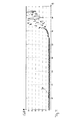
- Fig. 4 a series of goodness of fit values 34 as obtained from a multitude of measurements is plotted over time. All the measurements have been executed on the same battery 14, which was new and healthy at the time of the first measurement. Therefore, the goodness of fit values 34 are small and close to the ideal value of zero, at first. However, as is apparent from Fig. 4 , starting at a lifetime of about 6200 hours, the goodness of fit 34 increases steadily. This is due to a progressive deterioration of the battery 14, which is directly reflected by the time course of the goodness of fit 34.
- the goodness of fit 34 can be used as a simple yet reliable direct measure for the deterioration of a battery 14 and, thus, forms a good basis for the deterioration signal 26 generated and output by the battery deterioration system 10.
Abstract
The invention relates to a system (10) and method for determining the deterioration of a battery (14), particularly in an automotive system. The system comprises a battery sensor (12) configured to measure voltage values depending on respective voltages of the battery and to measure current values depending on respective currents of the battery; and an evaluation device (20)connected to the battery sensor for receiving the voltage and current values from the battery sensor, the evaluation device being adapted to generate a deterioration signal (26) in response to the received voltage and current values. The battery sensor is configured to synchronously measure a sequence of voltage values (22) and a sequence of current values (24), and the evaluation device is adapted to fit a model to said sequences, to derive a goodness of fit (34) from the fitting, and to generate the deterioration signal based on the goodness of fit.
Description
- The invention relates to a system and a method for determining the deterioration of a battery, particularly in an automotive system.
- In a modern vehicle, batteries, which typically are lead-acid type batteries, are playing an important role as storage of energy. Especially SLI (starting, lighting, ignition) batteries are essential to a vehicle's operation. Automotive batteries, however, can serve a wide variety of further purposes such as buffering during peak demands or providing energy to "living" systems of commercial vehicles, for example. Increasingly, automotive batteries also serve as storage for potentially to-be-recuperated energy such as braking energy.
- In order to reliably use a battery for those purposes, it is crucial to determine the internal state of the battery, i.e. to reliably estimate the battery's ability to provide energy and power, and particularly in what quantity energy and power can be provided.
- Several parameters for indicating the performance of a battery are known, some of them being defined by international standards. Such parameters are, for example, Cold Cranking Amperes (CCA) and the I/20 nominal capacity, the initial values of which are generally available from the battery specification. The CCA value indicates the battery's initial ability to deliver high current for short time events like engine cranks in low temperature. The I/20 nominal capacity indicates the battery's initial ability to deliver energy for a very precisely specified standard pulse according to EN 50342.
- However, because these parameters are initial values and defined for very special or even artificial measurement conditions, they are not sufficient for estimating the true available energy and power during the course of the battery lifetime for a multitude of typical use cases. This is why there is a need for battery monitor systems which allow determining the present state of a battery. Such a monitor system can be implemented by means of dedicated battery sensors (e.g. as part of a so called Battery Monitor, BM) for measuring current, voltage and temperature (IVT) values of the battery. The values can then be fed into a battery model which returns a deterioration signal as a measure for the battery state. The required calculations can be executed by an evaluation device, which can be integrated into or separate from the battery sensors.
- Due to their complexity, however, these battery models typically suffer from lack of exactness. Especially lead-acid type batteries are complex to model. Furthermore, the computation means of said Battery Monitors are limited, thus also limiting the possible complexity of the applied model.
- Another problem lies in that a model reproduces a theoretical behavior of the battery leading to abstract values. The battery state index returned by such a model, however, should allow for a simple qualitative assessment of the battery state in typical use cases. In other words, providing an index which refers to values only achievable e.g. by a high voltage charging method as required by a certain standard, but unfortunately never experienced in normal usage, dissatisfies the non-expert user.
- Some known battery models return an easily comprehensible index like the State of Charge (SoC), the State of Health (SoH), the State of Function (SoF), or a combination thereof. But these battery state indexes, although being intuitively understandable, are not universally and precisely defined. Attempts to define such an intuitive measure may often lead to inconsistent or arbitrarily detailed definitions.
- A quite general definition of the State of Health is based on the ratio between the actual capacity C act and the nominal capacity Cnom of the battery:

- The greater the difference between the actual capacity and the nominal capacity, the greater is the deterioration of the battery and the lower is the State of Health. The actual capacity, however, is hard to measure. Several different features of the battery can be considered as indicators for the actual capacity, e.g. the voltage change as a result of charging, the dynamic internal resistance, the spectral internal resistance, the charging current at the end of charge, or stress class statistics. In practice, establishing a reliable correlation between such features and the true actual capacity - especially for a wide spectrum of possible depletion modes - proves to be difficult.
- The invention is therefore based on the object of providing a system and a method for determining the deterioration of a battery which is simple and leads, on the one hand, to an intuitively comprehensible index and, on the other hand, to reliably measurable and comparable values.
- This problem is solved by a system as claimed in claim 1 as well as by a method as claimed in claim 9.
- In particular, the problem is solved by: synchronous measuring of a sequence of voltage values depending on respective voltages of the battery and of a sequence of current values depending on respective currents of the battery; subsequently fitting a battery state model to said sequences and deriving a goodness of fit from the fitting; and, finally, generating a deterioration signal based on the goodness of fit. This deterioration signal can then serve as an index for the state of the battery. The index can further be used to trigger a response depending on the battery state, e.g. to disable certain battery dependent services or to indicate a request to exchange the battery, if the battery deterioration exceeds certain levels.
- A principle idea of the invention is to use the goodness of fit value for quantitative assessment of the grade of depletion of the battery. The experience with aged and/or depleted batteries has shown that the agreement between the expected and the actually measured correlation of the voltage and current values decreases, when the battery state worsens. As has been found, the goodness of fit quite well reflects this decrease.
- The depletion can result from various impacts on the battery, such as wear-out, aging, or stress, which lead to battery deterioration. All these impacts have in common that they influence the dynamic internal resistance R IN. Being a measure for the correlation between the output voltages and the output currents of the battery, the dynamic internal resistance can easily be obtained by fitting a simple, in particular linear, model to measured sequences of voltage and current values.
- While it would be difficult to provide a reliable transfer function for the State of Health based on the internal resistance due to the fact that also the open circuit voltage, the temperature and internal resistances of parallelly connected loads and actuators would have to be taken in to account, a goodness of fit can be readily derived from the internal resistance by fitting an appropriate model to the voltage and current values. By using a fully deterministic fitting algorithm, a goodness of fit value can reproducibly be determined for a given set of voltage and current values.
- In order to be a good measure for the internal resistance the voltage and current values are to be measured synchronously. This means that for each voltage value of the sequence of voltage value there is a corresponding current value of the sequence of current values that has been measured essentially at the same time as the respective voltage value. Though the time intervals between subsequent measurements of voltage and current value pairs may vary, the sequence of measurements is preferentially isochronous.
- Furthermore, if a battery is configured as a multiple battery pack, voltage and current sequences are preferably measured for each battery of the battery pack individually.
- The goodness of fit can be a measure for the deviation between the fitted model and the original data the model is fitted to. In particular, a higher goodness of fit values can indicate a larger deviation. Then, the ideal goodness of fit value of zero means that the correlation between voltage and current of the battery (which usually corresponds to the internal resistance) is regular (i.e. in particular constant) during the whole duration of the measurement. Thus, a small goodness of fit value indicates that the battery's ability to provide energy is kept constant, which is a characteristic of a healthy battery.
- In contrast, a high goodness of fit value would indicate that during the duration of the measurements, especially under the stress of the initial demand for current, the characteristics of the battery change. Thus, the correlation between voltage and current deviates from the expected regular, e.g. linear, behavior which can be observed for a new and healthy battery. This deviation can directly and quantitatively be evaluated by calculating the goodness of fit.
- The benefit of the presented approach lies in that the weakness of a battery will be made "visible" by means of a goodness of fit value regardless of the root cause of the deterioration. Every deterioration mechanism, such as mechanical damage, corrosion, irreversible sulfation, water loss, and loss of active mass due to shedding, will cause a worsening of the goodness of fit value which can easily be determined.
- Advantageous embodiments of the invention can be found in the dependent claims, the description, and the figures.
- In accordance with an embodiment of the invention, the battery sensor of the system is configured to measure the sequence of voltage values and the sequence of current values during a high energy discharge pulse applied to the battery. Such a discharge pulse can in particular comprise a crank discharge pulse and can be part of normal vehicle operation or applied solely for the purpose of measurement. One advantage of measuring voltage and current during an energy discharge pulse of significant intensity relates to the fact that high voltage and current values exhibit a better signal-to-noise ratio than low values. Measuring of the sequences of voltage and current values preferably takes place recurrently, thus allowing for continuous monitoring of the battery state. Conveniently, during normal vehicle operation high energy discharge pulses occur sufficiently often for regular updates of the deterioration signal.
- In another embodiment of the invention, the model fitted to said sequences is a linear regression model. The slope of the model can then be interpreted as the internal resistance R IN, while the y-axis intercept can correspond to the open circuit voltage V 0. A linear regression model can easily be fitted to essentially linearly correlated data, such as the voltage and current values. Several reliable and efficient fitting algorithms for linear regression are known in the art.
- In accordance with an embodiment, the evaluation device of the system is adapted to fit the model to said sequences by approximation according to the method of least squares. A least square approximation is quite sensitive to data points deviating from the approximated fit. Therefore, it provides a good fitting precision. Furthermore, the squared deviation between the data points and the fitted model obtained during the approximation can readily be used for determining the goodness of fit, as will be explained later.
- According to an embodiment, the evaluation device is adapted to determine a sequence of error values derived from a respective deviation between the fitted model and the sequence of voltage values and/or the sequence of current values, wherein the goodness of fit is based on the sum of the error values, in particular the sum of the absolute error values. An error value can be derived for each data pair consisting of a voltage value and a corresponding current value from the sequences of voltage and current values. Thus, the sequence of error values preferably has the same length as the sequences of voltage and current values, respectively. In particular, this error value can be the difference between an approximated voltage value and the original voltage value or between an approximated current value and the original current value, or a combination thereof.
- From these error values, the goodness of fit can then be calculated by, for example, simply summing up the error values. A more rigorous goodness of fit can alternatively be obtained by first calculating the absolute values of the error values and then summing up these absolute values. Additionally, the respective sum of (direct or absolute) error values can be multiplied by a factor, e.g. a normalization factor or the inverse variance of the data set, or be otherwise further processed for the determination of the goodness of fit. Since the sum of error values increases with increasing deviation between the measured data and the fitted model, a low goodness of fit value indicates a good fit and, thus, low deterioration of the battery. However, there are other possible definitions of the goodness of fit, where a higher value corresponds to a better fit and a lower battery deterioration.
- In accordance with another embodiment, the evaluation device is adapted to determine a sequence of error values derived from a respective deviation between the fitted model and the sequence of voltage values and/or the sequence of current values, wherein the goodness of fit is based on the sum of the squared error values. Again, the sum can additionally be multiplied by a factor or be otherwise further processed. By squaring the error values, larger deviations between the original data and the fit are given more weight than smaller deviations. This leads to an even more rigorous definition of the goodness of fit which is more sensitive to a departure of the fitted model from the actual correlation between the voltage and the current of the battery. In this way, the deterioration signal is quasi amplified such that the battery state can be determined at a finer resolution.
- In order to indicate the state of the battery to a user, in a further embodiment of the invention, the system further comprises a display device configured to obtain the deterioration signal from the evaluation device and to indicate the deterioration of the battery in response to the deterioration signal. The display can be configured to display information about the deterioration of the battery continuously or only under specific circumstances such as after exceeding a threshold. Thus, a user can readily capture information on the battery state.
- In a preferred embodiment, the model relates the voltage values Vi to the current values Ii by the formula


- The goodness of fit GoF can be computed as the sum of residual errors of the fitting, which e.g. is a linear regression. In particular, the goodness of fit is one of


- Alternatively, the sequences of voltage and current values can be fitted by

- The error values can then be defined as ei = Ifitted,i - Ii .
- The characteristics and advantages described with respect to the claimed system and its embodiments are mutatis mutandis also applicable to the claimed method of determining the deterioration of a battery.
- In the following, different embodiments of the invention will be described purely by way of example with reference to the submitted drawing. The Figures of the drawing show:
- Fig. 1
- an embodiment of the battery deterioration determining system in a schematic representation;
- Fig. 2A and 2B
- diagrams showing the measured sequences of voltage and current values and the fitted correlation between voltage and current in case of a healthy battery;
- Fig. 3A and 3B
- diagrams showing the measured sequences of voltage and current values and the fitted correlation between voltage and current in case of a deteriorated battery;
- Fig. 4
- a diagram showing the development of the goodness of fit value over time for a progressively deteriorating battery.
-
Fig. 1 shows an embodiment of a batterydeterioration determining system 10. Thesystem 10 comprises abattery sensor 12, which is connectable to abattery 14. Thebattery 14 shown inFig. 1 is a lead-acid type SLI battery of a vehicle (not shown). Among other things, thebattery 14 serves as energy supply for astarter 16 of the vehicle's engine (not shown). - The
battery sensor 12 comprisesindividual sensing devices 18. One of thesensing devices 18 is a voltage meter V connected to thebattery 14, anothersensing device 18 is a current meter I inductively coupled to thebattery 14. In addition, thebattery sensor 12 has a temperature meter T, which determines the actual temperature from changes in thermal resistance. - The outputs of these
sensing devices 18 are fed to anevaluation device 20, which, in the case of the given embodiment, is integrated into thebattery sensor 12. - During a high energy crank discharge pulse, when the
starter 16 heavily draws current from thebattery 14, thebattery sensor 12 can synchronously measure a sequence ofvoltage values 22 by means of the voltage meter V and a sequence ofcurrent values 24 by means of the current meter I. Theevaluation device 20 receives these voltage andcurrent value sequences sensing devices 18 and fits a model for the correlation between these values to the data. - The fitting is performed by the
evaluation device 20 as a linear regression using the formula V = V 0 + I·R IN, wherein the approximation can also follow the method of least squares. As a result of the fitting procedure, the open circuit voltage V 0 and the internal resistance R IN can be obtained and be used to calculate voltage values V fitted,i for each current value Ii in accordance with the determined fitting coefficients V 0 and R IN. - The
evaluation device 20 can then derive a goodness of fit value GoF 34 (cf.Fig. 4 ) from the deviation between the calculated values Vfitted, i obtained from the fit and the original values Vi measured by thebattery sensor 12. Based on this goodness offit value 34 theevaluation device 20 generates adeterioration signal 26, which is output to adisplay device 28 of thesystem 10. In particular, thedisplay device 28 can be configured to optically indicate the state of thebattery 14 in response to the obtaineddeterioration signal 26. Alternatively or additionally, thedisplay device 28 can indicate a warning, if thedeterioration signal 26 exceeds a predetermined or chosen threshold. Moreover, thedisplay device 28 can also serve to indicate further information about thebattery 14, such as a state of charge. -
Fig. 2A shows a measured sequence ofvoltage values 22 superimposed with a measured sequence ofcurrent values 24, bothsequences battery 14 by thestarter 16. The correlation between thesesequences Fig. 2B , where the voltage values 22 are plotted against thecurrent values 24 in a scatter plot, with each dot of the plot representing a pair of voltage-current values 30. Thestraight line 32 describes the result of fitting the voltage-current correlation model to the measured values by linear regression. This fittedmodel 32 is then taken as reference to determine a sequence of error values, with each error value being calculated as the distance of an original voltage-current value pair 30 from the fittedmodel 32, wherein various known metrics can be used for the distance determination. - While
Fig. 2A and 2B show diagrams for data obtained from ahealthy battery 14, the diagrams ofFig. 3A and 3B show the same kind of data in an equivalent representation as inFig. 2A and 2B , respectively, for data which has been obtained from a deterioratedbattery 14. FromFig. 3A it is evident that the correlation between the voltage values 22 and thecurrent values 24 is not constant during the measurement. Thus, although the corresponding voltage-current value pairs 30 inFig. 3B can nevertheless be fitted by linear approximation, the fittedmodel 32 shows more deviation from the original data than was the case for thehealthy battery 14. Therefore, though it is hardly perceptible inFig. 3B , also the error values are collectively greater for the deterioratedbattery 14. - To determine a quantitative index for the deterioration of the
battery 14, a goodness offit 34 is derived from the error values by calculating the sum of the squares of the error values. - In
Fig. 4 a series of goodness offit values 34 as obtained from a multitude of measurements is plotted over time. All the measurements have been executed on thesame battery 14, which was new and healthy at the time of the first measurement. Therefore, the goodness offit values 34 are small and close to the ideal value of zero, at first. However, as is apparent fromFig. 4 , starting at a lifetime of about 6200 hours, the goodness offit 34 increases steadily. This is due to a progressive deterioration of thebattery 14, which is directly reflected by the time course of the goodness offit 34. - Hence, the goodness of
fit 34 can be used as a simple yet reliable direct measure for the deterioration of abattery 14 and, thus, forms a good basis for thedeterioration signal 26 generated and output by thebattery deterioration system 10. -
- 10
- battery deterioration determining system
- 12
- battery sensor
- 14
- battery
- 16
- starter
- 18
- sensing devices
- 20
- evaluation device
- 22
- sequence of voltage values
- 24
- sequence of current values
- 26
- deterioration signal
- 28
- display device
- 30
- voltage-current value pair
- 32
- fitted model
- 34
- goodness of fit
Claims (15)
- A system (10) for determining the deterioration of a battery (14), particularly in an automotive system, comprising:a battery sensor (12) configured to measure voltage values depending on respective voltages of the battery (14) and to measure current values depending on respective currents of the battery (14); andan evaluation device (20) connected to the battery sensor (12) for receiving the voltage and current values from the battery sensor (12), the evaluation device (20) being adapted to generate a deterioration signal (26) in response to the received voltage and current values;
characterized in thatthe battery sensor (12) is configured to synchronously measure a sequence of voltage values (22) and a sequence of current values (24), wherein the evaluation device (20) is adapted to fit a model to said sequences (22, 24), to derive a goodness of fit (34) from the fitting, and to generate the deterioration signal (26) based on the goodness of fit (34). - A system as claimed in claim 1,
characterized in that
the battery sensor (12) is configured to measure the sequence of voltage values (22) and the sequence of current values (24) during an energy discharge pulse, in particular a crank discharge pulse, applied to the battery (14). - A system as claimed in claim 1 or 2,
characterized in that
the model is a linear regression model. - A system as claimed in any of claims 1 to 3,
characterized in that
the evaluation device (20) is adapted to fit the model to said sequences (22, 24) by approximation according to the method of least squares. - A system as claimed in any of claims 1 to 4,
characterized in that
the evaluation device (20) is adapted to determine a sequence of error values derived from a respective deviation between the fitted model (32) and the sequence of voltage values (22) and/or the sequence of current values (24), wherein the goodness of fit (34) is based on the sum of the error values, in particular the sum of the absolute error values. - A system as claimed in any of claims 1 to 4,
characterized in that
the evaluation device (20) is adapted to determine a sequence of error values derived from a respective deviation between the fitted model (32) and the sequence of voltage values (22) and/or the sequence of current values (24), wherein the goodness of fit (34) is based on the sum of the squared error values. - A system as claimed in any of claims 1 to 6,
characterized in that
it further comprises a display device (28) configured to obtain the deterioration signal (26) from the evaluation device (20) and to indicate the deterioration of the battery (14) in response to the deterioration signal (26). - A system as claimed in any of claims 1 to 7,
characterized in that
the model relates the voltage values Vi to the current values Ii by the formula V = V 0 + I·R IN, wherein V is the voltage, I is the current, V 0 is the open circuit voltage, and R IN is the dynamic internal resistance of the battery (14), whereby every current value Ii is assigned a fitted voltage value V fitted,i = V 0+Ii ·R IN, wherein the goodness of fit GoF (34) is in particular one of GoF = ∑ i ei , GoF = ∑ i |ei |, and GoF= ∑ i ei 2, with ei = Vfitted,i -Vi being the deviation between the fitted model (32) and the voltage values. - A method of determining the deterioration of a battery (14), particularly in an automotive system, comprising:- measuring voltage values depending on respective voltages of the battery (14); and- measuring current values depending on respective currents of the battery (14);- generating a deterioration signal (26) in response to the voltage and current values;
characterized in that
said measuring of voltage and current values comprises synchronous measuring of a sequence of voltage values (22) and a sequence of current values (24), wherein said generating the deterioration signal (26) comprises:- fitting a model to said sequences (22, 24);- deriving a goodness of fit (34) from the fitting; and- generating the deterioration signal (26) based on the goodness of fit (34). - A method as claimed in claim 9,
characterized in that
the sequence of voltage values (22) and the sequence of current values (24) are measured during an energy discharge pulse, in particular a crank discharge pulse, applied to the battery (14). - A method as claimed in claim 9 or 10,
characterizedin that
the model is a linear regression model. - A method as claimed in any of claims 9 to 11,
characterized in that
said fitting of the model to said sequences (22, 24) comprises approximating the model to said sequences (22, 24) according to the method of least squares. - A method as claimed in any of claims 9 to 12,
characterized in that
said deriving of a goodness of fit (34) comprises determining a sequence of errors derived from a respective deviation between the fitted model (32) and the sequence of voltage values (22) and/or the sequence of current values (24), and calculating the sum of the errors, in particular the sum of the absolute errors. - A method as claimed in any of claims 9 to 12,
characterized in that
said deriving of a goodness of fit (34) comprises determining a sequence of errors derived from a respective deviation between the fitted model (32) and the sequence of voltage values (22) and/or the sequence of current values (24), and calculating the sum of the squared errors. - A method as claimed in any of claims 9 to 14,
characterized in that
the model relates the voltage values Vi to the current values Ii by the formula V = V 0+I·R IN, wherein V is the voltage, I is the current, V 0 is the open circuit voltage, and R IN is the dynamic internal resistance of the battery (14), whereby every current value Ii is assigned a fitted voltage value V fitted, i = V 0 + Ii ·R IN, wherein the goodness of fit GoF(34) is in particular one of GoF= ∑ i ei , GoF= ∑ i |ei |, and GoF= ∑ i ei 2, with ei = V fitted, i - Vi being the deviation between the fitted model (32) and the voltage values.
Priority Applications (1)
| Application Number | Priority Date | Filing Date | Title |
|---|---|---|---|
| EP13174720.6A EP2821803A1 (en) | 2013-07-02 | 2013-07-02 | Battery deterioration determining system |
Applications Claiming Priority (1)
| Application Number | Priority Date | Filing Date | Title |
|---|---|---|---|
| EP13174720.6A EP2821803A1 (en) | 2013-07-02 | 2013-07-02 | Battery deterioration determining system |
Publications (1)
| Publication Number | Publication Date |
|---|---|
| EP2821803A1 true EP2821803A1 (en) | 2015-01-07 |
Family
ID=48700448
Family Applications (1)
| Application Number | Title | Priority Date | Filing Date |
|---|---|---|---|
| EP13174720.6A Withdrawn EP2821803A1 (en) | 2013-07-02 | 2013-07-02 | Battery deterioration determining system |
Country Status (1)
| Country | Link |
|---|---|
| EP (1) | EP2821803A1 (en) |
Cited By (4)
| Publication number | Priority date | Publication date | Assignee | Title |
|---|---|---|---|---|
| WO2017050471A1 (en) * | 2015-09-24 | 2017-03-30 | Robert Bosch Gmbh | Method for monitoring a battery |
| CN112771708A (en) * | 2019-01-15 | 2021-05-07 | 五育电池株式会社 | Deterioration degree of storage element, storage battery power level detection device, and storage element management unit |
| CN114771440A (en) * | 2022-06-17 | 2022-07-22 | 深圳顶匠科技有限公司 | Vehicle starting signal generation method and device applied to storage battery state detection |
| WO2023220949A1 (en) * | 2022-05-18 | 2023-11-23 | 宁德时代新能源科技股份有限公司 | Battery swapping method, system and apparatus, storage medium, and computer program product |
Citations (4)
| Publication number | Priority date | Publication date | Assignee | Title |
|---|---|---|---|---|
| JPH04215083A (en) * | 1990-10-22 | 1992-08-05 | Yuasa Corp | Method for deciding remaining life of lead-acid battery |
| US20040251875A1 (en) * | 2003-06-10 | 2004-12-16 | Hitachi, Ltd. | Battery system, battery monitoring method and apparatus |
| JP2010036718A (en) * | 2008-08-05 | 2010-02-18 | Mitsubishi Motors Corp | Battery deterioration determination device |
| EP2551688A1 (en) * | 2011-07-25 | 2013-01-30 | Yokogawa Electric Corporation | Device, method and system for determining battery degradation |
-
2013
- 2013-07-02 EP EP13174720.6A patent/EP2821803A1/en not_active Withdrawn
Patent Citations (4)
| Publication number | Priority date | Publication date | Assignee | Title |
|---|---|---|---|---|
| JPH04215083A (en) * | 1990-10-22 | 1992-08-05 | Yuasa Corp | Method for deciding remaining life of lead-acid battery |
| US20040251875A1 (en) * | 2003-06-10 | 2004-12-16 | Hitachi, Ltd. | Battery system, battery monitoring method and apparatus |
| JP2010036718A (en) * | 2008-08-05 | 2010-02-18 | Mitsubishi Motors Corp | Battery deterioration determination device |
| EP2551688A1 (en) * | 2011-07-25 | 2013-01-30 | Yokogawa Electric Corporation | Device, method and system for determining battery degradation |
Cited By (5)
| Publication number | Priority date | Publication date | Assignee | Title |
|---|---|---|---|---|
| WO2017050471A1 (en) * | 2015-09-24 | 2017-03-30 | Robert Bosch Gmbh | Method for monitoring a battery |
| CN108027406A (en) * | 2015-09-24 | 2018-05-11 | 罗伯特·博世有限公司 | method for monitoring battery pack |
| CN112771708A (en) * | 2019-01-15 | 2021-05-07 | 五育电池株式会社 | Deterioration degree of storage element, storage battery power level detection device, and storage element management unit |
| WO2023220949A1 (en) * | 2022-05-18 | 2023-11-23 | 宁德时代新能源科技股份有限公司 | Battery swapping method, system and apparatus, storage medium, and computer program product |
| CN114771440A (en) * | 2022-06-17 | 2022-07-22 | 深圳顶匠科技有限公司 | Vehicle starting signal generation method and device applied to storage battery state detection |
Similar Documents
| Publication | Publication Date | Title |
|---|---|---|
| KR102080632B1 (en) | Battery management system and its operating method | |
| KR102452548B1 (en) | Apparatus for determination battery degradation, system having the same and method thereof | |
| CN108828461B (en) | Power battery SOH value estimation method and system | |
| KR101895619B1 (en) | State judging device, battery apparatus, state judging method | |
| KR100970841B1 (en) | Apparatus and Method for estimating battery's state of health based on battery voltage variation pattern | |
| CA3162747C (en) | Method for determining a state value of a traction battery | |
| US8159189B2 (en) | Battery state of health monitoring system and method | |
| US6967466B2 (en) | Method for determining the amount of charge which can be drawn on a storage battery, and monitoring device for a storage battery | |
| KR100759706B1 (en) | Method of estimating soc of battery for hybrid electric vehicle | |
| EP3410137B1 (en) | Cell state estimation device, cell control device, cell system, and cell state estimation method | |
| CN107925135B (en) | Degradation degree estimation device and degradation degree estimation method | |
| JP5535968B2 (en) | CHARGE RATE ESTIMATION DEVICE, CHARGE RATE ESTIMATION METHOD, AND PROGRAM | |
| JP6760119B2 (en) | Battery temperature estimation device, battery temperature estimation method and computer program | |
| EP2827162A1 (en) | Battery DC impedance measurement | |
| US20170160349A1 (en) | Battery state determining device | |
| EP3371613B1 (en) | A system and a method for determining state-of-charge of a battery | |
| KR102274383B1 (en) | Assessing the quantity of energy in a motor vehicle battery | |
| US20140095089A1 (en) | System and method for estimated battery state of charge | |
| EP2821803A1 (en) | Battery deterioration determining system | |
| JP2018173370A (en) | Abnormality determination device, abnormality determination method, and computer program | |
| KR20220147089A (en) | How to estimate the health of your battery | |
| CN112394290A (en) | Method and device for estimating SOH of battery pack, computer equipment and storage medium | |
| KR101726483B1 (en) | Apparatus and method for battery usage pattern analysis | |
| FR3009389A1 (en) | ENERGY MANAGEMENT IN A BATTERY | |
| US11255917B2 (en) | Method and system for improving battery capacity estimations |
Legal Events
| Date | Code | Title | Description |
|---|---|---|---|
| PUAI | Public reference made under article 153(3) epc to a published international application that has entered the european phase |
Free format text: ORIGINAL CODE: 0009012 |
|
| 17P | Request for examination filed |
Effective date: 20130702 |
|
| AK | Designated contracting states |
Kind code of ref document: A1 Designated state(s): AL AT BE BG CH CY CZ DE DK EE ES FI FR GB GR HR HU IE IS IT LI LT LU LV MC MK MT NL NO PL PT RO RS SE SI SK SM TR |
|
| AX | Request for extension of the european patent |
Extension state: BA ME |
|
| STAA | Information on the status of an ep patent application or granted ep patent |
Free format text: STATUS: THE APPLICATION IS DEEMED TO BE WITHDRAWN |
|
| 18D | Application deemed to be withdrawn |
Effective date: 20150708 |