EP2551632A2 - Optisches Bildgebungsverfahren und optische Bildgebungsvorrichtung - Google Patents
Optisches Bildgebungsverfahren und optische Bildgebungsvorrichtung Download PDFInfo
- Publication number
- EP2551632A2 EP2551632A2 EP12004990A EP12004990A EP2551632A2 EP 2551632 A2 EP2551632 A2 EP 2551632A2 EP 12004990 A EP12004990 A EP 12004990A EP 12004990 A EP12004990 A EP 12004990A EP 2551632 A2 EP2551632 A2 EP 2551632A2
- Authority
- EP
- European Patent Office
- Prior art keywords
- light
- phase
- interference
- optical imaging
- interference spectrum
- Prior art date
- Legal status (The legal status is an assumption and is not a legal conclusion. Google has not performed a legal analysis and makes no representation as to the accuracy of the status listed.)
- Withdrawn
Links
- 238000000034 method Methods 0.000 title claims abstract description 66
- 238000012634 optical imaging Methods 0.000 title claims abstract description 59
- 238000001514 detection method Methods 0.000 claims abstract description 52
- 238000003384 imaging method Methods 0.000 claims abstract description 43
- 238000001228 spectrum Methods 0.000 claims description 77
- 230000008859 change Effects 0.000 claims description 22
- 230000008569 process Effects 0.000 claims description 19
- 230000003287 optical effect Effects 0.000 claims description 7
- 238000012545 processing Methods 0.000 claims description 6
- 238000012014 optical coherence tomography Methods 0.000 description 55
- 239000000835 fiber Substances 0.000 description 38
- 239000013307 optical fiber Substances 0.000 description 16
- 230000003595 spectral effect Effects 0.000 description 15
- 238000013459 approach Methods 0.000 description 14
- 238000005259 measurement Methods 0.000 description 13
- 238000010586 diagram Methods 0.000 description 12
- 239000000523 sample Substances 0.000 description 7
- 230000001360 synchronised effect Effects 0.000 description 6
- 230000000694 effects Effects 0.000 description 4
- 230000009466 transformation Effects 0.000 description 4
- 230000008901 benefit Effects 0.000 description 3
- 239000000284 extract Substances 0.000 description 3
- 238000005070 sampling Methods 0.000 description 3
- 238000007796 conventional method Methods 0.000 description 2
- 238000001914 filtration Methods 0.000 description 2
- 238000001727 in vivo Methods 0.000 description 2
- 230000001678 irradiating effect Effects 0.000 description 2
- 230000004048 modification Effects 0.000 description 2
- 238000012986 modification Methods 0.000 description 2
- 210000001525 retina Anatomy 0.000 description 2
- 239000012472 biological sample Substances 0.000 description 1
- 238000004364 calculation method Methods 0.000 description 1
- 238000006243 chemical reaction Methods 0.000 description 1
- 230000001010 compromised effect Effects 0.000 description 1
- 230000008878 coupling Effects 0.000 description 1
- 238000010168 coupling process Methods 0.000 description 1
- 238000005859 coupling reaction Methods 0.000 description 1
- 238000000354 decomposition reaction Methods 0.000 description 1
- 230000007423 decrease Effects 0.000 description 1
- 230000001419 dependent effect Effects 0.000 description 1
- 230000008030 elimination Effects 0.000 description 1
- 238000003379 elimination reaction Methods 0.000 description 1
- 230000010354 integration Effects 0.000 description 1
- 238000005305 interferometry Methods 0.000 description 1
- 238000005457 optimization Methods 0.000 description 1
- 230000002207 retinal effect Effects 0.000 description 1
- 238000000926 separation method Methods 0.000 description 1
- 238000006467 substitution reaction Methods 0.000 description 1
- 230000001629 suppression Effects 0.000 description 1
- 238000013519 translation Methods 0.000 description 1
Images





Classifications
-
- G—PHYSICS
- G01—MEASURING; TESTING
- G01B—MEASURING LENGTH, THICKNESS OR SIMILAR LINEAR DIMENSIONS; MEASURING ANGLES; MEASURING AREAS; MEASURING IRREGULARITIES OF SURFACES OR CONTOURS
- G01B9/00—Measuring instruments characterised by the use of optical techniques
- G01B9/02—Interferometers
- G01B9/02001—Interferometers characterised by controlling or generating intrinsic radiation properties
- G01B9/0201—Interferometers characterised by controlling or generating intrinsic radiation properties using temporal phase variation
-
- A—HUMAN NECESSITIES
- A61—MEDICAL OR VETERINARY SCIENCE; HYGIENE
- A61B—DIAGNOSIS; SURGERY; IDENTIFICATION
- A61B3/00—Apparatus for testing the eyes; Instruments for examining the eyes
- A61B3/10—Objective types, i.e. instruments for examining the eyes independent of the patients' perceptions or reactions
- A61B3/102—Objective types, i.e. instruments for examining the eyes independent of the patients' perceptions or reactions for optical coherence tomography [OCT]
-
- G—PHYSICS
- G01—MEASURING; TESTING
- G01B—MEASURING LENGTH, THICKNESS OR SIMILAR LINEAR DIMENSIONS; MEASURING ANGLES; MEASURING AREAS; MEASURING IRREGULARITIES OF SURFACES OR CONTOURS
- G01B9/00—Measuring instruments characterised by the use of optical techniques
- G01B9/02—Interferometers
- G01B9/02001—Interferometers characterised by controlling or generating intrinsic radiation properties
- G01B9/02002—Interferometers characterised by controlling or generating intrinsic radiation properties using two or more frequencies
- G01B9/02004—Interferometers characterised by controlling or generating intrinsic radiation properties using two or more frequencies using frequency scans
-
- G—PHYSICS
- G01—MEASURING; TESTING
- G01B—MEASURING LENGTH, THICKNESS OR SIMILAR LINEAR DIMENSIONS; MEASURING ANGLES; MEASURING AREAS; MEASURING IRREGULARITIES OF SURFACES OR CONTOURS
- G01B9/00—Measuring instruments characterised by the use of optical techniques
- G01B9/02—Interferometers
- G01B9/02055—Reduction or prevention of errors; Testing; Calibration
- G01B9/02062—Active error reduction, i.e. varying with time
- G01B9/02067—Active error reduction, i.e. varying with time by electronic control systems, i.e. using feedback acting on optics or light
- G01B9/02069—Synchronization of light source or manipulator and detector
-
- G—PHYSICS
- G01—MEASURING; TESTING
- G01B—MEASURING LENGTH, THICKNESS OR SIMILAR LINEAR DIMENSIONS; MEASURING ANGLES; MEASURING AREAS; MEASURING IRREGULARITIES OF SURFACES OR CONTOURS
- G01B9/00—Measuring instruments characterised by the use of optical techniques
- G01B9/02—Interferometers
- G01B9/02055—Reduction or prevention of errors; Testing; Calibration
- G01B9/02075—Reduction or prevention of errors; Testing; Calibration of particular errors
- G01B9/02078—Caused by ambiguity
-
- G—PHYSICS
- G01—MEASURING; TESTING
- G01B—MEASURING LENGTH, THICKNESS OR SIMILAR LINEAR DIMENSIONS; MEASURING ANGLES; MEASURING AREAS; MEASURING IRREGULARITIES OF SURFACES OR CONTOURS
- G01B9/00—Measuring instruments characterised by the use of optical techniques
- G01B9/02—Interferometers
- G01B9/0209—Low-coherence interferometers
- G01B9/02091—Tomographic interferometers, e.g. based on optical coherence
Definitions
- the present invention relates to an optical imaging method and an optical imaging apparatus using optical coherence tomography.
- OCT Optical coherence tomography
- FD-OCT Fourier domain OCT
- TD-OCT time domain OCT
- FD-OCT includes spectral domain OCT (abbreviated SD-OCT) in which the interference light is detected through spectral decomposition and swept source OCT (abbreviated SS-OCT) in which interference lights of various wavelengths are obtained using a wavelength-swept light source.
- SD-OCT spectral domain OCT
- SS-OCT swept source OCT
- I k s k ⁇ I R + I S + ⁇ - ⁇ + ⁇ 2 ⁇ I R ⁇ I S ⁇ cos kz + ⁇ 0 z ⁇ dz
- Equation (1) is simplified as the following.
- I k ⁇ - ⁇ + ⁇ A z ⁇ cos kz + ⁇ 0 z ⁇ dz
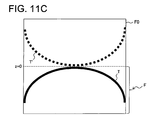
- Fig. 11A shows a true image T of the object drawn in the full frame F0.
- the mirror image T' complex conjugate artifact
- the true image T appears as shown in Fig. 11B .
- the measurement depth of the object is shifted to separate the true image T and the mirror image T' from each other (see Fig. 11C ).
- the drawing range of the true image T that is, the upper half of the frame F0 is wasted, and the imaging depth is halved. Consequently, the demand to obtain the broadest possible image range is restricted.
- phase shifting non-patent documents 1-3
- BM mode scanning non-patent documents 4-9
- frequency shifting non-patent documents 10, 11
- 3x3 fiber-optical coupler non-patent documents 12-14
- phase modulation pattern 1, non-patent documents 15-18
- Phase shifting is a method well known in the field of Fourier optics, in which each spectral interferogram is obtained with different initial phases while moving the reference mirror stepwise by a distance on the order of light wavelengths.
- Phase shifting-based techniques require accurate phase changes between adjacent A-lines. These techniques are limited by devices such as a piezo stage or electrical phase modulator. Moreover, these techniques are compromised by factors such as mechanical instability of a system and chromatic errors.
- BM mode scanning is a technique that is an extension of phase shifting, in which phases are changed during transverse scanning.
- the method of changing a phase includes a method in which the phase is changed stepwise (non-patent documents 8, 9) and a method in which the phase is changed linearly (non-patent documents 4-7).
- the former has some of the drawbacks of phase shifting and is not cost-effective in achieving a stepwise phase change. The latter causes an undesirable situation in which the path length is changed when the range of transverse scanning is widened.
- Frequency shifting is a method based on frequency separation and is only applicable to SS-OCT. Moreover, frequency shifting requires expensive devices such as EOM (electro-optic modulators) and AOM (acousto-optic modulators) in order to shift the signal to a higher frequency band. As a result, this system also requires significantly high speed data acquisition devices.
- 3x3 fiber-optical coupler-based techniques suffer from wavelength-dependent coupling coefficients for broadband and require additional costly detectors.
- Phase modulation techniques are more recently reported methods, in which complex conjugate artifacts are removed by adding a sinusoidal phase modulation.
- Phase modulation is usually introduced by a dithering mirror driven by a piezo stage provided with the reference arm.
- One approach relies on the integration effect of the camera, so its application is restricted to SD-OCT (non-patent document 17).
- Other approaches extract complex signals from multiple harmonic signals generated by the modulation based on complicated Bessel functions. This causes several major problems. For example, it requires extra decoding hardware, or higher load computation if decoding is performed by software.
- the object of the present invention is to provide a technique capable of extending the imaging depth range at a lower cost.
- An optical imaging method for forming a tomographic image of an object by processing an interference spectrum based on an interference light that is obtained by combining a signal light passing through said object and a reference light characterized in that the method comprises: a scanning step to scan the object with the signal light while alternately changing the phase difference between the signal light and the reference light to two preset phase differences; a detection step to detect the interference light of said signal light passing through said object and said reference light; and an imaging step to form the tomographic image of said object based on the detection results of a plurality of said interference lights sequentially obtained in said detection step according to said scanning.
- said scanning may be performed by sequentially changing the irradiation position of said signal light on said object, and by synchronizing the irradiation timing of said signal light on said object and the changing timing of said phase difference.
- said signal light may be irradiated on said object at a substantially constant time interval, and the frequency for the alternating change of said phase difference is substantially 1/2 of said time interval.
- the alternating change of said phase difference may be performed by alternately changing the phase of said reference light between two phases.
- the alternating change of said phase difference may be performed by alternately changing the phase of said signal light between two phases.
- a complex interference spectrum consisting of complex numbers may be generated based on the detection results of said interference light, and said tomographic image may be formed based on this complex interference spectrum.
- Said process of generating said complex interference spectrum may comprise: a process of obtaining a first interference spectrum by applying a low pass filter to the interference spectrum based on the detection results of said interference light, and obtaining a real part by dividing said first interference spectrum by the cosine of said phase difference; a process of obtaining a second interference spectrum by multiplying the interference spectrum based on said detection results by -(-1) n and applying a low pass filter on this product, and obtaining an imaginary part by dividing said second interference spectrum by the sine of said phase difference; and a process of generating said complex interference spectrum by adding said real part and a product obtained by multiplying said imaginary part by an imaginary unit.
- n is the identification number of the axial line indicating the position of the A-line in the transverse scanning.
- Said imaging step may be configured to include a process of generating, based on the detection results of the interference lights, an interference spectrum that has, as domain of definition, the region having the two phase differences at both ends and that consists of a low frequency part with a background component as its center and a high frequency part present around each of said both ends.
- Said scanning in said scanning step may be configured to perform at an oversampling ratio at which said low frequency part and said high frequency part are separated.
- Said two phase differences may be substantially + ⁇ /4 and - ⁇ /4.
- the optical imaging apparatus comprises: a light source; an optical member that divides the light output from said light source into a signal light and a reference light; a scanner that changes the irradiation position of said signal light on an object; a phase changing part that alternately changes the phase difference between said signal light and said reference light to two preset phase differences; an optical member that generates an interference light by combining the signal light passing through said object and the reference light, a detector that detects said interference light; and an imaging part that forms a tomographic image of said object based on the detection results of a plurality of said interference lights sequentially obtained by said detector according to the change in the irradiation position of said signal light.
- the apparatus may further comprise a controller that controls said light source and said phase changing part to synchronize the irradiation timing of said signal light on said object and the changing timing of said phase difference.
- Said controller may be configured to control said light source to irradiate said signal light on said object at a substantially constant time interval, and to control said phase changing part to alternately change said phase difference at a frequency of substantially 1/2 of said time interval.
- Said phase changing part may be configured to alternately change said phase difference by alternately changing the phase of said reference light between the two preset phases.
- Said phase changing part may be configured to alternately change said phase difference by alternately changing the phase of said signal light between the two preset phases.
- Said imaging part may be configured to comprise a generator that generates a complex interference spectrum consisting of complex numbers based on the detection results of said interference light, and that forms said tomographic image based on this complex interference spectrum.
- Said generator may be configured to: obtain a first interference spectrum by applying a low pass filter to the interference spectrum based on the detection results of said interference light, and obtain a real part by dividing said first interference spectrum by the cosine of said phase difference; obtain a second interference spectrum by multiplying the interference spectrum based on said detection results by -(-1) n and applying a low pass filter on this product, and obtain an imaginary part by dividing said second interference spectrum by the sine of said phase difference; and generate said complex interference spectrum by adding said real part and a product obtained by multiplying said imaginary part by an imaginary unit.
- Said imaging part may generate, based on the detection results of the interference lights, an interference spectrum that has, as domain of definition, the region having the two phase differences at both ends and that consists of a low frequency part with a background component as its center and a high frequency part present around each of said both ends.
- the optical imaging apparatus may comprise a controller that controls said light source and said scanner to scan said object with said signal light at an oversampling ratio at which said low frequency part and said high frequency part are separated.
- Said two phase differences may be substantially + ⁇ /4 and - ⁇ /4.
- the present invention by forming a tomographic image based on the plurality of detection results sequentially obtained by performing scanning while alternately changing the phase difference between the signal light and the reference light to two phase differences, it is possible to extend the imaging depth range at a lower cost.
- data is acquired by performing transverse scanning (B-scanning) while changing the phase between two values in an alternating manner (i.e., alternately), and a spectral interferogram (complex interferogram or complex interference spectrum) consisting of complex numbers is generated based on the acquired data. Then, by reconstructing the image based on this complex interferogram, a tomographic image (B-scanning image) without a mirror image is obtained. As a result, extension of the imaging depth range, which is the object, is achieved. Moreover, as described later, the apparatus of this embodiment can achieve this object by only slightly adding a configuration to the conventional FD-OCT, i.e., at a lower cost.
- A-line scanning is a mode for collecting the spectral interferogram in which the profile in the axial line direction of the object is encoded.
- A-line scanning in SS-OCT is a mode for sequentially irradiating light with a plurality of wavelengths on each A-line
- A-line scanning in SD-OCT is a mode for irradiating a broadband light of various wavelengths on each A-line.
- transverse scanning is a mode for sequentially scanning a plurality of A-lines in order to form two-dimensional tomographic images. After removing the background component from the collected data, the spectral interferogram collected by transverse scanning is expressed as follows:
- n is the identification number of the axial line indicating the position of the A-line in transverse scanning.
- Transverse scanning is synchronized with A-line scanning by certain signals such as A-line trigger signals.
- the A-line trigger signal indicates the timing for starting each A-line scanning, and is generated by the wavelength-swept light source driver in SS-OCT or the interference light detection module in SD-OCT.
- the transverse scanning rate f s is defined as the repetition frequency for A-line scanning. Since a plurality of A-lines are generally aligned at a constant interval along the transverse scanning direction, the transverse scanning rate f s can be regarded as the transverse sampling rate.
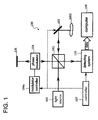
- An optical imaging apparatus 100 is an apparatus that forms a tomographic image of an object (sample) 1000, and comprises a light source 101, a beam splitter 102, a scanner 103, a phase modulator 104, a modulation controller 104a, a reference mirror 105, a detection system 106, a controller 107, and a computer 108.
- the light output from the light source 101 is divided into a signal light and a reference light by the beam splitter 102.
- the scanner 103 scans the object 1000 with the signal light.
- the reflected light and backscattered light of the signal light from the object 1000 are returned to the beam splitter 102 through the scanner 103.
- the phase modulator 104 is controlled by the modulation controller 104a to modulate the phase of the reference light.
- the reference light is reflected by the reference mirror 105 and returned to the beam splitter 102 by way of the phase modulator once again.
- the beam splitter 102 superposes the respectively returned signal light and the reference light to generate interference light.
- This interference light is detected by the detection system 106.
- the detection system 106 sends the detected data to the computer 108.
- the computer 108 forms an image of the object corresponding to the scanning range of the signal light based on this detection data.
- the controller 107 performs synchronization control of the scanner 103, modulation controller 104a, and detection
- phase modulator 104 is for modulating the phase of light and is installed in the reference arm or the sample arm. It is noteworthy that the phase change used in the present embodiment should be referred to as "phase alternation" rather than phase modulation.
- Phase alternation means that two phase statuses + ⁇ and - ⁇ are alternately applied corresponding to the sequential detection of a plurality of A-lines (i.e., corresponding to transverse scanning). In other words, the initial phases in the sequential detection of a plurality of A-lines will be ⁇ , - ⁇ , ⁇ , - ⁇ , ⁇ , ....
- Examples of the control for achieving this include a method in which the phase alternation and scanning on a plurality of A-lines are synchronized and the phase alternation is performed at a frequency f s /2 that is 1/2 the scanning frequency on the A-line (i.e., the transverse scanning rate f s ).
- the spectral interferogram to be detected is expressed as follows:
- I ⁇ k ⁇ n ⁇ - ⁇ + ⁇ A z ⁇ n cos kz + ⁇ 0 z ⁇ n + - 1 n ⁇ ⁇ ⁇ ⁇ ⁇ dz
- Equation (4) can be expanded to:
- I ⁇ k ⁇ n ⁇ - ⁇ + ⁇ A z ⁇ n cos ⁇ ⁇ ⁇ ⁇ cos kz + ⁇ 0 z ⁇ n - - 1 n ⁇ sin ⁇ ⁇ ⁇ ⁇ sin kz + ⁇ 0 z ⁇ n ⁇ dz
- Equation (5) The first term in Equation (5) is the same as in Equation (3) except for a weight factor cos( ⁇ ).
- the second term in Equation (5) alternates at the frequency f s /2 due to the existence of the alternating term (-1) n .
- the first term and the second term can be separated in the frequency domain.
- the alternating frequency f s /2 is merely half the transverse scanning rate f s
- SD-OCT using CCD for example, can be used for detection.
- Fig. 2 shows an example of the frequency spectrum of I'(k,n) that can be obtained by transverse scanning.
- This frequency spectrum contains a low frequency part LF1 centered at the background component DC and a high frequency part HF1 centered at the frequency f s /2.
- the low frequency part LF1 corresponds to the first term in Equation (5) and the high frequency part HF1 corresponds to the second term in Equation (5).
- this spectrum is limited to the range [-f s /2, f s /2]. Frequencies greater than f s /2 and frequencies less than -f s /2 can be brought to this range by adding mf s .
- m is a positive or negative integer.
- Equation (5) the first term and the second term in Equation (5) can be extracted separately as shown in the following equation:
- I im (k, n) can be derived by numerically shifting the frequency of the second term in Equation (2) by f s /2.
- I re (k, n) and I im (k, n) can be recombined to obtain the complex interferogram as shown in the following equation:
- Fig. 3 shows an example of the process in which the complex signal I * (k, n) is generated from the phase alternating signal I'(k, n) and an image is formed.
- a new signal I"(k, n) is generated by multiplying the detected spectral interferogram I'(k, n) by -(-1) n . This operation shifts the second term mentioned above back to the background component, and corrects its sign ( ⁇ ).
- a low pass filter in the transverse frequency domain is applied to both I'(k, n) and I"(k, n) to yield I re (k, n) and I im (k, n), respectively, shown in Equation (6).
- I re (k, n) and I im (k, n) are combined to generate the complex signal I * (k, n) shown in Equation (7).
- fast Fourier transformation is applied to the complex signal I * (k, n) to reconstruct an image 208 that is free of complex conjugate artifacts.
- an interferogram 301 corresponding to a single depth is generated by putting a certain object (for example, single surface mirror) into the sample arm and the reference arm, and performing normal FD-OCT measurement.
- Fast Fourier transformation (302) is applied to this interferogram 301 to form an image 303.
- a mirror image 303a and a true image 303b of the certain object are drawn in the image 303.
- the true image b is extracted through the filtering process (304) to form an image 305.
- inverse fast Fourier transformation (306) is applied to the image 306 to obtain an interferogram 307.
- the phase of the interferogram 307 for each A-line is calculated as ⁇ .
- ⁇ can be statistically estimated by comparing the intensities of I re (k, n) and I im (k, n). For example, the absolute values of I re (k, n) and I im (k, n) are calculated by addition in the transverse scanning direction, and their ratio can be calculated as follows:
- Equation (8) can be statistically simplified as follows:
- cos( ⁇ ) and sin( ⁇ ) can be calculated using tan( ⁇ ) or ⁇ .
- the sign of tan( ⁇ ) or ⁇ is either positive or negative, but its sign is not critical since both cases provide images that are free from complex conjugate artifacts. However, when needed, their sign can be obtained as the sign of the phase between odd and even A-lines. For example, assuming that the total number of A-lines constructing one image is N (N is an even number), the image to be reconstructed is expressed as follows:
- ⁇ is a function of the wave number k. Therefore, the statistically estimated tan( ⁇ ) or ⁇ is a curve along the wave number k that is smoothened, e.g., by curve fitting or filtering to eliminate the statistical noise.
- the intensities of I re (k, n) and I im (k, n) need to be balanced to avoid large errors occurring in each part. This means tan( ⁇ ) ⁇ 1, i.e., ⁇ /4 would be an optimal number. It is also possible to tune the phase modulator 104 to obtain a ⁇ so that tan( ⁇ ) ⁇ 1 for the entire spectrum. Therefore, the complex interferogram shown in Equation (7) is further simplified as follows:
- I * k ⁇ n I rs k ⁇ n + j ⁇ I im k ⁇ n
- this embodiment is particularly effective for scattering mediums such as living tissue, for example, the human retina.
- the present embodiment handles only two frequency parts, and optimization of the oversampling ratio is substantially easy as compared to the case in which five or more frequency parts are handled as in patent document 1 and non-patent documents 15, 16 and 18.
- FIG. 6 A configuration example of the optical imaging apparatus according to this embodiment is shown in Fig. 6 .
- an apparatus using SS-OCT will be described herein, a similar configuration can also be applied to an apparatus using SD-OCT. That is, the difference between the apparatus using SS-OCT according the invention and the apparatus using SD-OCT according to the invention is merely the general difference between SS-OCT and SD-OCT.
- An optical imaging apparatus 400 shown in Fig. 6 has a wavelength-swept light source 401 such as a wavelength-variable laser.
- the wavelength-swept light source 401 outputs a light while continuously changing the wavelength at a high speed.
- the light output from the wavelength-swept light source 401 travels through an optical fiber 402 and is directed to a fiber coupler 403.
- the fiber coupler 403 connects four optical fibers 402, 404, 410 and 412 with each other.
- the light directed by the optical fiber 402 is divided into a signal light and a reference light by the fiber coupler 403.
- the signal light is a light irradiated on the object, and is also referred to as a measurement light or a sample light.
- the reference light is combined with the signal light through a predetermined reference path.
- the signal light is directed by the optical fiber 404 to be emitted from the fiber end, and made into a parallel pencil by a collimator 405.
- the signal light that has become a parallel pencil travels through a scanner 406 and is focused on the fundus Ef of an eye E by lenses 407 and 408.
- the scanner 406 changes the irradiation position of the signal light on the fundus Ef.
- a galvano scanner, a polygon mirror, a resonant scanner, an acousto-optical modulator, a rotating prism, a vibrating prism, etc. are used.
- the light path created by the optical fiber 404, collimator 405, scanner 406 and lenses 407 and 408 is referred to as, for example, a signal light path or a sample arm.
- the signal light irradiated on the fundus Ef is scattered by various tissues of the fundus Ef. Among these scattered lights, backscattered light is returned to the fiber coupler 403 through the signal light path. Moreover, this backscattered light is directed to the fiber coupler 413 by the optical fiber 412. The backscattered light includes depth information of the fundus Ef.
- the reference light generated by the fiber coupler 403 is directed to the fiber coupler 413 by the optical fiber 410.
- a fiber stretcher 411 is provided on the way in the optical fiber 410.
- the fiber stretcher 411 receives an electrical driving signal from a fiber stretcher driving part 417 and changes the length of the optical fiber 410 by a small amount proportional to the voltage of the driving signal.
- ⁇ V is the amplitude of the driving signal.
- the fiber stretcher 411 alternatively changes the phase of the reference light between two phases ⁇ . Consequently, the phase difference between the signal light and the reference light is alternately changed to two preset phase differences.
- the fiber stretcher 411 constitutes an example of the "phase changing part" along with the fiber stretcher driving part 417.
- the phase changing part not only the fiber stretcher, but also any devices capable of switching two phase statuses can be used, such as an electrical/optical phase modulator, an optical switch, a wave plate, a translation stage, a piezo, etc.
- the path of the reference light is referred to as a reference light path or a reference arm.
- the phase changing part may be provided to only the reference arm as in this embodiment, or may be provided to only the sample arm, or may be provided to both the reference arm and the sample arm. That is, the phase changing part may take any concrete configuration or arrangement as long as it alternately changes the phase difference between the signal light and the reference light to two preset phase differences.
- the fiber coupler 413 connects four optical fibers 410, 412, 414a and 414b with each other.
- the branch ratio of the fiber coupler 413 is, for example, 1:1.
- the signal light and the reference light are combined by the fiber coupler 413 to generate interference light.
- This interference light takes over depth information of the fundus Ef included in the signal light and information on the phase change provided to the reference light.
- a detector 415 detects the interference light directed by the optical fibers 414a and 414b.
- the detector 415 is a balanced detector that has, for example, two photo detectors and outputs the difference between the detection results by them.
- the detector 415 sends its detection results (detected signals) to a data acquisition system 416 every time it detects the interference light.
- the data acquisition system 416 collects detected signals that are sequentially input from the detector 415.
- the data acquisition system 416 sends these detected signals to an arithmetic controller 420 collectively, for example, at each series of wavelength sweeps, that is, at for each A-line.
- the arithmetic controller 420 reconstructs each A-line profile (A-line image) based on the data input from the data acquisition system 416 using the above-mentioned principle. Moreover, the arithmetic controller 420 forms a B-scanning image (tomographic image) by aligning a plurality of A-line profiles in one column according to the scanning pattern of the signal light. In addition, the arithmetic controller 420 can align a plurality of B-scanning images according to the scanning pattern of the signal light to generate stack data, and can generate volume data by applying image processing such as interpolation to this stack data.
- a user interface (man-machine interface) 430 includes a display device, an input device and an operation device.
- the display device for example, an LCD is used.
- the input device and the operation device include various hardware keys (switch, button, knob, joystick, etc.) provided with the optical imaging apparatus 400.
- hardware keys provided with an apparatus for example, keyboard, pointing device, etc., provided with a computer
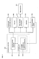
- FIG. 7 A configuration example of a control system of the optical imaging apparatus 400 is shown in Fig. 7 .
- An arithmetic controller 240 has a function of controlling each part of the optical imaging apparatus 400 and a function of performing various arithmetic processing.
- the arithmetic controller 420 has a synchronization controller 421 and an imaging part 422.
- the image controller 422 has a complex interference spectrum generator 423.
- the synchronization controller 421 is an example of the "controller” and the complex interference spectrum controller 423 is an example of the "generator.”
- the synchronization controller 421 performs synchronization control for performing OCT measurement. To this end, the synchronization controller 421 controls the wavelength-swept light source 401, the scanner 406, the fiber stretcher driving part 417, the detector 415, and the data acquisition system 416. As a control of the wavelength-swept light source 401, the synchronization controller 421 controls the on/off of the wavelength-swept light source 401 and change of wavelength at a high speed. As a control of the scanner 406, the synchronization controller 421 changes the irradiation position of the signal light on the fundus Ef by, for example, changing the direction of the galvano mirror.
- the synchronization controller 421 sends a signal to drive the fiber stretcher 411 to the fiber stretcher driving part 417.
- the synchronization controller 421 controls the timing to detect the interference light and the timing to output the detected signal.
- the synchronization part 421 causes to output the acquired data.
- the synchronization controller 421 sends a control signal to each part that is a control target.
- This control signal is an electrical signal including a frequency component of the transverse scanning rate f s as described above.
- This control signal is an electrical signal with, for example, the frequency f s .
- a sinusoidal electrical signal is used as this control signal, but its waveform is not limited to this.
- two or more control signals can also be used. For example, it is possible to send a control signal with the frequency f s to the wavelength-swept light source 401 and the scanner 406, and send an electrical signal with the frequency f s /2 to the fiber stretcher driving part 417.
- the wavelength-swept light source 401 Based on the control signal, the wavelength-swept light source 401 repeatedly outputs the light while changing the wavelength at a high speed.
- the scanner 406 deflects the signal light in the order corresponding to the arrangement of a plurality of A-lines according to the preset scanning pattern.
- the fiber stretcher driving part 417 Based on the control signal, the fiber stretcher driving part 417 generates the driving signal for alternately changing the phase of the reference light and sends it to the fiber stretcher 411.
- the control signals the operation of the wavelength-swept light source 401, the operation of the scanner 406 and the operation of the fiber stretcher 411 are synchronized.
- the scanner 406 performs transverse scanning on the arrangement of a plurality of A-lines, and the wavelength-swept light source 401 performs A-line scanning in which lights of a series of wavelengths are irradiated on each A-line, and the fiber stretcher 411 performs phase alternation at a frequency that is 1/2 the transverse scanning rate.
- the configuration of the fiber stretcher driving part 417 for generating a driving signal with the frequency f s /2 from a control signal with the frequency f s will be described.
- This signal conversion processing is performed by, for example, a J-K flip-flop 4171, a narrow band pass (NBP) filter 4172, and a phase shifter 4173 as shown in Fig. 8 .
- NBP narrow band pass
- the J-K flip-flop 4171 decreases the frequency f s of the control signal input from the synchronization controller 421 to half f s /2 and outputs it to a narrow band pass filter 4172.
- the narrow band pass filter 4172 extracts a first-order harmonic signal, i.e., a sine signal at the frequency f s /2 from the electric signal input from the J-K flip-flop 4171 and outputs it to a phase shifter 4173.
- the phase shifter 4173 in order to precisely adjust the gap in timing between the A-line acquisition and phase alternation, changes the phase of the sine signal input from the narrow band pass filter 4172 and outputs it to the switch 4174.
- the switch 4174 receives (other) control signals from the arithmetic controller 420 and establishes/disconnects the electrical connection between the phase shifter 4173 and the fiber stretcher 411. That is, the switch 4174 establishes the electrical connection when performing measurements according to the present embodiment, and disconnects the electrical connection when performing conventional measurements.
- the command for such a change in the measurement mode is carried out using, for example, the user interface 430. That is, the user can selectively use the measurement mode according to the present embodiment and the normal, conventional measurement mode.
- A-line identification data (A-line ID)" is the identification data assigned to each of a plurality of A-lines according to the scanning pattern.
- A-line trigger indicates a pulse signal representing the timing of the output of a light for measuring each A-line to the wavelength-swept light source 401. This pulse signal is generated by the driving part (not shown) included in, for example, the wavelength-swept light source 401. It should be noted that the synchronization controller 421 may be configured to generate such pulse signals.
- Driving signal represents a sine signal that is sent from the fiber stretcher driving part 417 to the fiber stretcher 411.
- the frequency of the driving signal is half the frequency of the A-line trigger.
- Phase alternation status represents the status of the alternating phase between + ⁇ and - ⁇ , which is specified by the sinusoidal driving signal according to the timing of the A-line trigger.
- Phase alternation represents the status of the phase alternation of the reference light according to the alternating phase specified from the sinusoidal driving signal.
- the detector 415 sequentially detects the interference light corresponding to the light that is repeatedly output by the wavelength-swept light source 401, and sequentially outputs the resultant electrical signals (detected signals).
- the data acquisition system 416 collects detected signals that are sequentially output from the detector 415 and sends them to the imaging part 422.
- information corresponding to the control signal for example, A-line identification data
- the complex interference spectrum generator 423 summarizes the data input from the data acquisition system 416 for each A-line, and generates a complex interference spectrum (complex interferogram) for each A-line according to the above-mentioned principle.
- the imaging part 422 forms the image for each above-mentioned A-line based on the complex interference spectrum for each A-line. Moreover, the imaging part 422 forms a tomographic image of the object by arranging the images for the plurality of A-lines according to the scanning pattern.
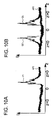
- the inventors performed measurement of a human eye using such a phase alternating SS-OCT.
- the A-line profile obtained by this example is shown in Fig. 10A .
- the A-line profile obtained by the conventional method is shown in Fig. 10B .
- the lateral axis of each A-line profile indicates the depth z
- the longitudinal axis indicates the intensity I of the backscattered light.
- the A-line profile AP2 according to the conventional method includes a true image Q1 as well as its complex conjugate, a mirror image Q2.
- the A-line profile AP1 according to the present example does not have a mirror image, and includes only a true image P1.
- the optical imaging apparatus 400 forms a tomographic image of an object by processing an interference spectrum based on interference lights that are obtained by combining signal lights passing through the object and reference lights, and performs the scanning step, the detection step, and the imaging step.
- the optical imaging apparatus 400 scans the object with the signal light while alternately changing the phase difference between the signal light and the reference light to two preset phase differences.
- This scanning step is performed by the wavelength-swept light source 401, the scanner 406, the fiber stretcher 411, the fiber stretcher driving part 417, etc., under the control of the synchronization controller 421.
- the detection step interference light of the signal light passing through the object and the reference light is detected.
- This detection step is performed by the detector 415 and the data acquisition system 416 in parallel with the scanning step.
- the imaging step a tomographic image of the object is formed based on the detection results of a plurality of the interference lights sequentially obtained in the detection step according to the scanning. This imaging step is performed by the imaging part 422.
- scanning can be performed by sequentially changing the irradiation position of the signal light on the object, as well as the irradiation timing of the signal light on the object and the change timing of the phase difference can be synchronized.
- the signal light may be irradiated on the object at a substantially equivalent interval, and the frequency for the alternating change of the phase difference can be substantially 1/2 the time interval.
- the alternating change of the phase difference may be performed by alternately changing the phase of the reference light between two phases.
- a complex interference spectrum consisting of complex numbers may be generated based on the detection results of the interference light, and the tomographic image can be formed based on the complex interference spectrum.
- the process of generating the complex interference spectrum may include the following three processes:
- the imaging step it may be configured to perform a process of generating, based on the detection results of the interference lights, an interference spectrum that has, as domain of definition, the region having the two phase differences at both ends and that consists of a low frequency part with a background component as its center and a high frequency part present around each of the above-mentioned both ends; and, in the scanning step, scanning may be performed at an oversampling ratio at which the low frequency part and the high frequency part are separated.
- the above-mentioned two phase differences may be substantially + ⁇ /4 and - ⁇ /4.
- a complex interference spectrum is generated by newly introducing the approach of "phase alternation" that can be achieved by a simple configuration, and by reconstructing this, an image that is free of mirror images can be obtained. Consequently, it is possible to extend the imaging depth range at a lower cost. This extension of the imaging depth range is twice that in the conventional case in which the interference spectrum of the real value is generated.
- phase alternation approach has an advantage in that it can be used in both SS-OCT and SD-OCT.
- phase alternation approach has an advantage in that the setting and adjustment of the apparatus are easier and the control to change the phase is easier compared to conventional approaches such as phase shifting, BM mode scanning, and phase modulation.
- the approach of the present embodiment is to obtain a series of interference spectra, each encoded by the phase alternation (interference spectra corresponding to a plurality of A-lines arranged in the transverse scanning direction). Therefore, the present approach is essentially different from conventional approaches in which Fourier transformation is applied to each of a plurality of interference spectra.
- the two phase statuses ⁇ in the phase alternation approach may be arbitrary, giving it a significantly high degree of freedom compared to conventional approaches.
- the value for ⁇ is not limited to ⁇ /4 and may be any value as described above.
- phase alternation approach is also characterized in that a higher harmonic wave is not present. This is due to the fact that only two phase statuses are used, and is significantly different from the conventional phase modulation associated with a higher harmonic wave. While in the conventional phase modulation approach, it is necessary to prevent a number of harmonic signals from being overlapped with each other, such as 0th order, 1st order, 2nd order, 3rd order,... in the order from the background component side, in the present embodiment, it is only necessary to consider the low frequency part and high frequency part as shown in Fig. 5A and Fig. 5B , making calibration easy.
Landscapes
- Physics & Mathematics (AREA)
- General Physics & Mathematics (AREA)
- Health & Medical Sciences (AREA)
- Life Sciences & Earth Sciences (AREA)
- General Health & Medical Sciences (AREA)
- Engineering & Computer Science (AREA)
- Nuclear Medicine, Radiotherapy & Molecular Imaging (AREA)
- Radiology & Medical Imaging (AREA)
- Surgery (AREA)
- Biophysics (AREA)
- Heart & Thoracic Surgery (AREA)
- Medical Informatics (AREA)
- Molecular Biology (AREA)
- Ophthalmology & Optometry (AREA)
- Animal Behavior & Ethology (AREA)
- Biomedical Technology (AREA)
- Public Health (AREA)
- Veterinary Medicine (AREA)
- Automation & Control Theory (AREA)
- Optics & Photonics (AREA)
- Investigating Or Analysing Materials By Optical Means (AREA)
- Eye Examination Apparatus (AREA)
Applications Claiming Priority (1)
| Application Number | Priority Date | Filing Date | Title |
|---|---|---|---|
| US13/190,676 US8564788B2 (en) | 2011-07-26 | 2011-07-26 | Optical imaging method and optical imaging apparatus |
Publications (2)
| Publication Number | Publication Date |
|---|---|
| EP2551632A2 true EP2551632A2 (de) | 2013-01-30 |
| EP2551632A3 EP2551632A3 (de) | 2013-05-08 |
Family
ID=46934358
Family Applications (1)
| Application Number | Title | Priority Date | Filing Date |
|---|---|---|---|
| EP12004990.3A Withdrawn EP2551632A3 (de) | 2011-07-26 | 2012-07-05 | Optisches Bildgebungsverfahren und optische Bildgebungsvorrichtung |
Country Status (3)
| Country | Link |
|---|---|
| US (1) | US8564788B2 (de) |
| EP (1) | EP2551632A3 (de) |
| JP (2) | JP5936930B2 (de) |
Cited By (2)
| Publication number | Priority date | Publication date | Assignee | Title |
|---|---|---|---|---|
| EP2639545A1 (de) * | 2012-03-13 | 2013-09-18 | Kabushiki Kaisha TOPCON | Optisches Bildgebungsverfahren und optische Bildgebungsvorrichtung |
| JP2014176566A (ja) * | 2013-03-15 | 2014-09-25 | Canon Inc | 画像処理システム、画像処理方法及びプログラム。 |
Families Citing this family (10)
| Publication number | Priority date | Publication date | Assignee | Title |
|---|---|---|---|---|
| US10317189B2 (en) | 2014-01-23 | 2019-06-11 | Kabushiki Kaisha Topcon | Detection of missampled interferograms in frequency domain OCT with a k-clock |
| JP6728007B2 (ja) * | 2016-09-23 | 2020-07-22 | 株式会社Screenホールディングス | 撮像装置および撮像方法 |
| WO2018160561A1 (en) * | 2017-02-28 | 2018-09-07 | Photonicare, Inc. | Image based handheld imager system and methods of use |
| WO2019202602A1 (en) * | 2018-04-19 | 2019-10-24 | Ariel Scientific Innovations Ltd. | Method and system for interferometry |
| IT201800007723A1 (it) * | 2018-08-01 | 2020-02-01 | Costr Strumenti Oftalmici Cso Srl | Apparecchiatura di tomografia a coerenza ottica del tipo "fourier-domain" con rimozione di artefatti indesiderati attraverso elaborazione di immagine digitale |
| CN109507117B (zh) * | 2018-11-12 | 2020-04-03 | 中国科学技术大学 | 一种基于光声束整形的微纳成像检测实验装置 |
| US20220065615A1 (en) * | 2018-12-20 | 2022-03-03 | Nec Corporation | Optical coherence tomography device |
| EP4117504B1 (de) * | 2020-03-10 | 2025-10-01 | Leica Microsystems NC, Inc. | Systeme, verfahren und computer programm produkt zur identifizierung eines konjugats in einem bild |
| US12416574B2 (en) | 2021-05-07 | 2025-09-16 | Nec Corporation | Measurement method, measurement device, and nontransitory computer-readable medium |
| CN115950532A (zh) * | 2022-12-21 | 2023-04-11 | 苏州中科行智智能科技有限公司 | 一种光学相干层析成像装置及方法 |
Citations (1)
| Publication number | Priority date | Publication date | Assignee | Title |
|---|---|---|---|---|
| WO2006127952A2 (en) | 2005-05-23 | 2006-11-30 | Southwest Sciences Incorporated | Method and apparatus for full phase interferometry |
Family Cites Families (11)
| Publication number | Priority date | Publication date | Assignee | Title |
|---|---|---|---|---|
| US5321501A (en) * | 1991-04-29 | 1994-06-14 | Massachusetts Institute Of Technology | Method and apparatus for optical imaging with means for controlling the longitudinal range of the sample |
| JP3594875B2 (ja) * | 2000-05-25 | 2004-12-02 | 独立行政法人 科学技術振興機構 | 2次元光ヘテロダイン検出法を用いた光画像計測装置 |
| EP1611411A2 (de) * | 2003-03-26 | 2006-01-04 | Southwest Sciences Incorporated | Verfahren und vorrichtung zur abbildung interner strukturen transparenter und durchscheinender materialien |
| JP4505807B2 (ja) * | 2004-08-09 | 2010-07-21 | 国立大学法人 筑波大学 | 多重化スペクトル干渉光コヒーレンストモグラフィー |
| US7433046B2 (en) * | 2004-09-03 | 2008-10-07 | Carl Ziess Meditec, Inc. | Patterned spinning disk based optical phase shifter for spectral domain optical coherence tomography |
| US7330270B2 (en) * | 2005-01-21 | 2008-02-12 | Carl Zeiss Meditec, Inc. | Method to suppress artifacts in frequency-domain optical coherence tomography |
| JP2009530614A (ja) * | 2006-03-16 | 2009-08-27 | デューク ユニバーシティ | フーリエ領域光コヒーレンス・トモグラフィーに基づく実時間直角位相投影を実行するための方法、システム及びコンピュータプログラム製品 |
| JP5149535B2 (ja) * | 2007-04-27 | 2013-02-20 | 国立大学法人 筑波大学 | 偏光感受型光コヒーレンストモグラフィー装置、該装置の信号処理方法、及び該装置における表示方法 |
| JP2011047815A (ja) * | 2009-08-27 | 2011-03-10 | Sumitomo Electric Ind Ltd | Oct装置 |
| WO2011037980A2 (en) * | 2009-09-22 | 2011-03-31 | Bioptigen, Inc. | Systems for extended depth frequency domain optical coherence tomography (fdoct) and related methods |
| JP5025715B2 (ja) * | 2009-12-08 | 2012-09-12 | キヤノン株式会社 | 断層画像撮影装置、画像処理装置、画像処理システム、画像処理装置の制御方法及びプログラム |
-
2011
- 2011-07-26 US US13/190,676 patent/US8564788B2/en not_active Expired - Fee Related
-
2012
- 2012-06-21 JP JP2012140027A patent/JP5936930B2/ja active Active
- 2012-07-05 EP EP12004990.3A patent/EP2551632A3/de not_active Withdrawn
-
2016
- 2016-01-28 JP JP2016014785A patent/JP6190900B2/ja active Active
Patent Citations (1)
| Publication number | Priority date | Publication date | Assignee | Title |
|---|---|---|---|---|
| WO2006127952A2 (en) | 2005-05-23 | 2006-11-30 | Southwest Sciences Incorporated | Method and apparatus for full phase interferometry |
Non-Patent Citations (18)
Cited By (3)
| Publication number | Priority date | Publication date | Assignee | Title |
|---|---|---|---|---|
| EP2639545A1 (de) * | 2012-03-13 | 2013-09-18 | Kabushiki Kaisha TOPCON | Optisches Bildgebungsverfahren und optische Bildgebungsvorrichtung |
| US8896841B2 (en) | 2012-03-13 | 2014-11-25 | Kabushiki Kaisha Topcon | Optical imaging method and optical imaging apparatus using optical coherence tomography |
| JP2014176566A (ja) * | 2013-03-15 | 2014-09-25 | Canon Inc | 画像処理システム、画像処理方法及びプログラム。 |
Also Published As
| Publication number | Publication date |
|---|---|
| EP2551632A3 (de) | 2013-05-08 |
| JP2013029500A (ja) | 2013-02-07 |
| JP6190900B2 (ja) | 2017-08-30 |
| US8564788B2 (en) | 2013-10-22 |
| JP5936930B2 (ja) | 2016-06-22 |
| JP2016057318A (ja) | 2016-04-21 |
| US20130027712A1 (en) | 2013-01-31 |
Similar Documents
| Publication | Publication Date | Title |
|---|---|---|
| US8564788B2 (en) | Optical imaging method and optical imaging apparatus | |
| US8896841B2 (en) | Optical imaging method and optical imaging apparatus using optical coherence tomography | |
| US12396640B2 (en) | Frequency-domain interferometric based imaging systems and methods | |
| US10571243B2 (en) | Systems and methods for improved OCT measurements | |
| JP5448353B2 (ja) | 光干渉断層計を用いた画像形成方法、及び光干渉断層装置 | |
| Hillmann et al. | Common approach for compensation of axial motion artifacts in swept-source OCT and dispersion in Fourier-domain OCT | |
| CN102105105B (zh) | 扩展范围成像 | |
| US10502544B2 (en) | Efficient sampling of optical coherence tomography data for explicit ranging over extended depth | |
| JP5752955B2 (ja) | 光断層像撮影装置 | |
| US20080204762A1 (en) | Methods, systems, and computer program products for removing undesired artifacts in fourier domain optical coherence tomography (FDOCT) systems using integrating buckets | |
| WO2012140229A2 (en) | Systems and methods for swept-source optical coherence tomography | |
| JP6685673B2 (ja) | 撮像装置 | |
| Wang | Fourier domain optical coherence tomography achieves full range complex imaging in vivo by introducing a carrier frequency during scanning | |
| Poddar et al. | In vitro 3D anterior segment imaging in lamb eye with extended depth range swept source optical coherence tomography | |
| EP2757345B1 (de) | Bildmessverfahren und Bildmessvorrichtung | |
| JP5784100B2 (ja) | 画像形成装置及び画像形成方法 | |
| Lu et al. | Two-harmonic complex spectral-domain optical coherence tomography using achromatic sinusoidal phase modulation | |
| Huang et al. | High speed full range imaging with harmonic detection swept source optical coherence tomography | |
| Fabritius et al. | Complex conjugate resolved retinal imaging by one-micrometer spectral domain optical coherence tomography using an electro-optical phase modulator | |
| Bajraszewski et al. | Spectral Optical Coherence Tomography using scanning optical frequency comb generator | |
| Baumann | Polarization sensitive optical coherence tomography in the human eye | |
| Hammer et al. | Three-dimensional tracker for spectral domain optical coherence tomography | |
| Yamanari et al. | Full range polarization-sensitive swept-source optical coherence tomography at 1 um with polarization modulation and BM-mode scan | |
| Choi | Ultra-fast Fourier domain optical coherence tomography using optical Demultiplexers |
Legal Events
| Date | Code | Title | Description |
|---|---|---|---|
| PUAI | Public reference made under article 153(3) epc to a published international application that has entered the european phase |
Free format text: ORIGINAL CODE: 0009012 |
|
| AK | Designated contracting states |
Kind code of ref document: A2 Designated state(s): AL AT BE BG CH CY CZ DE DK EE ES FI FR GB GR HR HU IE IS IT LI LT LU LV MC MK MT NL NO PL PT RO RS SE SI SK SM TR |
|
| AX | Request for extension of the european patent |
Extension state: BA ME |
|
| PUAL | Search report despatched |
Free format text: ORIGINAL CODE: 0009013 |
|
| AK | Designated contracting states |
Kind code of ref document: A3 Designated state(s): AL AT BE BG CH CY CZ DE DK EE ES FI FR GB GR HR HU IE IS IT LI LT LU LV MC MK MT NL NO PL PT RO RS SE SI SK SM TR |
|
| AX | Request for extension of the european patent |
Extension state: BA ME |
|
| RIC1 | Information provided on ipc code assigned before grant |
Ipc: A61B 3/10 20060101ALI20130402BHEP Ipc: G01B 9/02 20060101AFI20130402BHEP |
|
| 17P | Request for examination filed |
Effective date: 20131107 |
|
| RBV | Designated contracting states (corrected) |
Designated state(s): AL AT BE BG CH CY CZ DE DK EE ES FI FR GB GR HR HU IE IS IT LI LT LU LV MC MK MT NL NO PL PT RO RS SE SI SK SM TR |
|
| STAA | Information on the status of an ep patent application or granted ep patent |
Free format text: STATUS: THE APPLICATION HAS BEEN WITHDRAWN |
|
| 18W | Application withdrawn |
Effective date: 20140612 |