EP2551029B1 - Vorrichtung und Verfahren zur elektrohydraulischen Steuerung der Parallelität in einer Biegemaschine zur Bearbeitung von Metallprodukten - Google Patents
Vorrichtung und Verfahren zur elektrohydraulischen Steuerung der Parallelität in einer Biegemaschine zur Bearbeitung von Metallprodukten Download PDFInfo
- Publication number
- EP2551029B1 EP2551029B1 EP12177973.0A EP12177973A EP2551029B1 EP 2551029 B1 EP2551029 B1 EP 2551029B1 EP 12177973 A EP12177973 A EP 12177973A EP 2551029 B1 EP2551029 B1 EP 2551029B1
- Authority
- EP
- European Patent Office
- Prior art keywords
- pump
- operating fluid
- parallelism
- actuating means
- roller
- Prior art date
- Legal status (The legal status is an assumption and is not a legal conclusion. Google has not performed a legal analysis and makes no representation as to the accuracy of the status listed.)
- Active
Links
Images
Classifications
-
- B—PERFORMING OPERATIONS; TRANSPORTING
- B21—MECHANICAL METAL-WORKING WITHOUT ESSENTIALLY REMOVING MATERIAL; PUNCHING METAL
- B21D—WORKING OR PROCESSING OF SHEET METAL OR METAL TUBES, RODS OR PROFILES WITHOUT ESSENTIALLY REMOVING MATERIAL; PUNCHING METAL
- B21D5/00—Bending sheet metal along straight lines, e.g. to form simple curves
- B21D5/14—Bending sheet metal along straight lines, e.g. to form simple curves by passing between rollers
-
- B—PERFORMING OPERATIONS; TRANSPORTING
- B21—MECHANICAL METAL-WORKING WITHOUT ESSENTIALLY REMOVING MATERIAL; PUNCHING METAL
- B21C—MANUFACTURE OF METAL SHEETS, WIRE, RODS, TUBES, PROFILES OR LIKE SEMI-MANUFACTURED PRODUCTS OTHERWISE THAN BY ROLLING; AUXILIARY OPERATIONS USED IN CONNECTION WITH METAL-WORKING WITHOUT ESSENTIALLY REMOVING MATERIAL
- B21C51/00—Measuring, gauging, indicating, counting, or marking devices specially adapted for use in the production or manipulation of material in accordance with subclasses B21B - B21F
-
- F—MECHANICAL ENGINEERING; LIGHTING; HEATING; WEAPONS; BLASTING
- F15—FLUID-PRESSURE ACTUATORS; HYDRAULICS OR PNEUMATICS IN GENERAL
- F15B—SYSTEMS ACTING BY MEANS OF FLUIDS IN GENERAL; FLUID-PRESSURE ACTUATORS, e.g. SERVOMOTORS; DETAILS OF FLUID-PRESSURE SYSTEMS, NOT OTHERWISE PROVIDED FOR
- F15B11/00—Servomotor systems without provision for follow-up action; Circuits therefor
- F15B11/16—Servomotor systems without provision for follow-up action; Circuits therefor with two or more servomotors
- F15B11/22—Synchronisation of the movement of two or more servomotors
-
- F—MECHANICAL ENGINEERING; LIGHTING; HEATING; WEAPONS; BLASTING
- F15—FLUID-PRESSURE ACTUATORS; HYDRAULICS OR PNEUMATICS IN GENERAL
- F15B—SYSTEMS ACTING BY MEANS OF FLUIDS IN GENERAL; FLUID-PRESSURE ACTUATORS, e.g. SERVOMOTORS; DETAILS OF FLUID-PRESSURE SYSTEMS, NOT OTHERWISE PROVIDED FOR
- F15B13/00—Details of servomotor systems ; Valves for servomotor systems
- F15B13/02—Fluid distribution or supply devices characterised by their adaptation to the control of servomotors
- F15B13/06—Fluid distribution or supply devices characterised by their adaptation to the control of servomotors for use with two or more servomotors
-
- F—MECHANICAL ENGINEERING; LIGHTING; HEATING; WEAPONS; BLASTING
- F15—FLUID-PRESSURE ACTUATORS; HYDRAULICS OR PNEUMATICS IN GENERAL
- F15B—SYSTEMS ACTING BY MEANS OF FLUIDS IN GENERAL; FLUID-PRESSURE ACTUATORS, e.g. SERVOMOTORS; DETAILS OF FLUID-PRESSURE SYSTEMS, NOT OTHERWISE PROVIDED FOR
- F15B2211/00—Circuits for servomotor systems
- F15B2211/20—Fluid pressure source, e.g. accumulator or variable axial piston pump
- F15B2211/205—Systems with pumps
- F15B2211/20576—Systems with pumps with multiple pumps
-
- F—MECHANICAL ENGINEERING; LIGHTING; HEATING; WEAPONS; BLASTING
- F15—FLUID-PRESSURE ACTUATORS; HYDRAULICS OR PNEUMATICS IN GENERAL
- F15B—SYSTEMS ACTING BY MEANS OF FLUIDS IN GENERAL; FLUID-PRESSURE ACTUATORS, e.g. SERVOMOTORS; DETAILS OF FLUID-PRESSURE SYSTEMS, NOT OTHERWISE PROVIDED FOR
- F15B2211/00—Circuits for servomotor systems
- F15B2211/20—Fluid pressure source, e.g. accumulator or variable axial piston pump
- F15B2211/255—Flow control functions
-
- F—MECHANICAL ENGINEERING; LIGHTING; HEATING; WEAPONS; BLASTING
- F15—FLUID-PRESSURE ACTUATORS; HYDRAULICS OR PNEUMATICS IN GENERAL
- F15B—SYSTEMS ACTING BY MEANS OF FLUIDS IN GENERAL; FLUID-PRESSURE ACTUATORS, e.g. SERVOMOTORS; DETAILS OF FLUID-PRESSURE SYSTEMS, NOT OTHERWISE PROVIDED FOR
- F15B2211/00—Circuits for servomotor systems
- F15B2211/40—Flow control
- F15B2211/415—Flow control characterised by the connections of the flow control means in the circuit
- F15B2211/41563—Flow control characterised by the connections of the flow control means in the circuit being connected to a pressure source and a return line
-
- F—MECHANICAL ENGINEERING; LIGHTING; HEATING; WEAPONS; BLASTING
- F15—FLUID-PRESSURE ACTUATORS; HYDRAULICS OR PNEUMATICS IN GENERAL
- F15B—SYSTEMS ACTING BY MEANS OF FLUIDS IN GENERAL; FLUID-PRESSURE ACTUATORS, e.g. SERVOMOTORS; DETAILS OF FLUID-PRESSURE SYSTEMS, NOT OTHERWISE PROVIDED FOR
- F15B2211/00—Circuits for servomotor systems
- F15B2211/40—Flow control
- F15B2211/42—Flow control characterised by the type of actuation
- F15B2211/426—Flow control characterised by the type of actuation electrically or electronically
-
- F—MECHANICAL ENGINEERING; LIGHTING; HEATING; WEAPONS; BLASTING
- F15—FLUID-PRESSURE ACTUATORS; HYDRAULICS OR PNEUMATICS IN GENERAL
- F15B—SYSTEMS ACTING BY MEANS OF FLUIDS IN GENERAL; FLUID-PRESSURE ACTUATORS, e.g. SERVOMOTORS; DETAILS OF FLUID-PRESSURE SYSTEMS, NOT OTHERWISE PROVIDED FOR
- F15B2211/00—Circuits for servomotor systems
- F15B2211/40—Flow control
- F15B2211/45—Control of bleed-off flow, e.g. control of bypass flow to the return line
-
- F—MECHANICAL ENGINEERING; LIGHTING; HEATING; WEAPONS; BLASTING
- F15—FLUID-PRESSURE ACTUATORS; HYDRAULICS OR PNEUMATICS IN GENERAL
- F15B—SYSTEMS ACTING BY MEANS OF FLUIDS IN GENERAL; FLUID-PRESSURE ACTUATORS, e.g. SERVOMOTORS; DETAILS OF FLUID-PRESSURE SYSTEMS, NOT OTHERWISE PROVIDED FOR
- F15B2211/00—Circuits for servomotor systems
- F15B2211/60—Circuit components or control therefor
- F15B2211/63—Electronic controllers
- F15B2211/6303—Electronic controllers using input signals
- F15B2211/6336—Electronic controllers using input signals representing a state of the output member, e.g. position, speed or acceleration
-
- F—MECHANICAL ENGINEERING; LIGHTING; HEATING; WEAPONS; BLASTING
- F15—FLUID-PRESSURE ACTUATORS; HYDRAULICS OR PNEUMATICS IN GENERAL
- F15B—SYSTEMS ACTING BY MEANS OF FLUIDS IN GENERAL; FLUID-PRESSURE ACTUATORS, e.g. SERVOMOTORS; DETAILS OF FLUID-PRESSURE SYSTEMS, NOT OTHERWISE PROVIDED FOR
- F15B2211/00—Circuits for servomotor systems
- F15B2211/70—Output members, e.g. hydraulic motors or cylinders or control therefor
- F15B2211/71—Multiple output members, e.g. multiple hydraulic motors or cylinders
- F15B2211/7107—Multiple output members, e.g. multiple hydraulic motors or cylinders the output members being mechanically linked
-
- F—MECHANICAL ENGINEERING; LIGHTING; HEATING; WEAPONS; BLASTING
- F15—FLUID-PRESSURE ACTUATORS; HYDRAULICS OR PNEUMATICS IN GENERAL
- F15B—SYSTEMS ACTING BY MEANS OF FLUIDS IN GENERAL; FLUID-PRESSURE ACTUATORS, e.g. SERVOMOTORS; DETAILS OF FLUID-PRESSURE SYSTEMS, NOT OTHERWISE PROVIDED FOR
- F15B2211/00—Circuits for servomotor systems
- F15B2211/70—Output members, e.g. hydraulic motors or cylinders or control therefor
- F15B2211/71—Multiple output members, e.g. multiple hydraulic motors or cylinders
- F15B2211/7142—Multiple output members, e.g. multiple hydraulic motors or cylinders the output members being arranged in multiple groups
-
- F—MECHANICAL ENGINEERING; LIGHTING; HEATING; WEAPONS; BLASTING
- F15—FLUID-PRESSURE ACTUATORS; HYDRAULICS OR PNEUMATICS IN GENERAL
- F15B—SYSTEMS ACTING BY MEANS OF FLUIDS IN GENERAL; FLUID-PRESSURE ACTUATORS, e.g. SERVOMOTORS; DETAILS OF FLUID-PRESSURE SYSTEMS, NOT OTHERWISE PROVIDED FOR
- F15B2211/00—Circuits for servomotor systems
- F15B2211/70—Output members, e.g. hydraulic motors or cylinders or control therefor
- F15B2211/765—Control of position or angle of the output member
- F15B2211/7656—Control of position or angle of the output member with continuous position control
-
- F—MECHANICAL ENGINEERING; LIGHTING; HEATING; WEAPONS; BLASTING
- F15—FLUID-PRESSURE ACTUATORS; HYDRAULICS OR PNEUMATICS IN GENERAL
- F15B—SYSTEMS ACTING BY MEANS OF FLUIDS IN GENERAL; FLUID-PRESSURE ACTUATORS, e.g. SERVOMOTORS; DETAILS OF FLUID-PRESSURE SYSTEMS, NOT OTHERWISE PROVIDED FOR
- F15B2211/00—Circuits for servomotor systems
- F15B2211/70—Output members, e.g. hydraulic motors or cylinders or control therefor
- F15B2211/78—Control of multiple output members
- F15B2211/782—Concurrent control, e.g. synchronisation of two or more actuators
Definitions
- the technical field to which the present invention relates is the field of bending machines for bending sheet metals or metal plates, section bars and the like.
- the present invention relates to an apparatus and to a method for the electrohydraulic control of the parallelism of a roller of a bending machine for processing metal pieces according to the preamble of claims 1 and 7.
- Such an apparatus and such a method are for example disclosed in JP-A-59225821 .
- the invention further relates to a bending machine with two or more bending machine rollers for bending metal products such sheet metals, metal plates, section bars or the like, provided with a control apparatus as mentioned above.
- Apparatuses are known for controlling the parallelism of the rollers of machines for bending a sheet metal such as to obtain an end product having a desired shape or with an appropriate radius of curvature. Such apparatuses act, during working of a sheet metal, to maintain the longitudinal axis of a first roller, that is movable, parallel to itself or parallel to the longitudinal axis of a second fixed roller, depending on the type of working operation to be performed.
- a control apparatus 100 for a bending machine comprises a hydraulic pump P100 that supplies pressurised oil to a first lifting hydraulic actuator C101 and to a second lifting hydraulic actuator C102, which are connected to opposite ends of a movable roller R100.
- the first C101 and the second C102 hydraulic actuator act for lifting the movable roller R100, which in this manner moves in relation to a dragging roller with a fixed longitudinal axis.
- the hydraulic pump P100 sends high-pressure oil to a hydraulic circuit 101 connected in common to the first C101 and to the second C102 lifting hydraulic actuator.
- the hydraulic circuit 101 comprises a first portion 102, connected directly to the pump P100, which branches off into a first and second circuit branch, which are connected respectively to the first C101 and to the second C102 lifting hydraulic actuator, and along which a first VD101 and a second VD102 directional valve are respectively provided that are commanded to control the flow direction of the oil.
- the two circuit branches have respectively a first proportional flow valve VP101 and a second proportional flow valve VP102 placed in series along the respective delivery paths of the high-pressure oil to the first C101 and second C102 hydraulic actuators.
- There are provided a first T101 and a second T102 position transducer which are arranged to detect the position of a respective end of the movable roller R100.
- An electronic control unit U100 is provided that is operationally connected to the first T101 and second T102 position transducer, to the first VP101 and second VP102 proportional valve and to the first VD101 and second VD102 directional valve.
- a maximum valve Vmax is provided that is suitable for sending pressurised oil coming from the pump P100 directly into a tank 103 of the circuit 100 if the pressure of the oil reaches a set maximum safety value.
- the pump P100 circulates the oil that flows freely first through the first VP101 and second VP102 proportional flow valves, and subsequently through the first VD101 and second VD102 directional valves, which in turn send the oil to the first C101 and second C102 hydraulic actuators, which are in turn driven to raise or lower the movable roller R100.
- the first T101 and the second T102 position transducer send the signals to the control unit U100, which compares, in real time, step by step, the various positions taken by the movable roller R100, which in this manner can be moved parallel to itself.
- the electronic control unit U100 drives for closing the second proportional valve VP102 such as to "throttle", i.e. reduce the flowrate of oil to the second actuator C102.
- the speed at which the second actuator C102 moves is thus reduced proportionally to the throttling to which the second proportional valve VP102 is subjected.
- first VP101 and second VP102 proportional flow valves are thus normally open but are continuously more or less closed, according to what has been disclosed above, if a condition of non parallelism of the movable roller R100 with respect to the fixed roller occurs.
- One of the aforesaid proportional valves VP101, VP102 is variably closed according to the amount of the deviation of the movable roller R100 from the parallelism condition.
- a drawback of such a known control apparatus is that for ensuring parallelism in the bending machine perfect operation of the electronic componentry is required, in particular of the proportional valves VP101, VP102, which are always at risk in very corrosive and dirty environments such as mechanical shops for processing a sheet metal. Further, in such environments there is often calamine, which is harmful to the electronic componentry, which is also sorely tried by the continuous and violent electric shocks that occur during welding operations of metal workpieces. In the event of a fault or malfunction in the proportional valves VP101, VP102, because it is not longer possible to maintain and ensure the parallelism condition between the movable roller R100 and the fixed roller, the machine would no longer be usable in any way until the fault had been completely eliminated. In such cases, a machine downtime results that is financially damaging because of the drop in productivity.
- this pressure increase which is due to throttling, prevents the bending capacity of the bending machine from being exploited to the full.
- correcting the parallelism leads to having continuous overpressure compared with the normal pressure values that are strictly necessary for being able to bend a metal plate.
- the aforesaid overpressure is such as to make the maximum valve Vmax intervene very frequently to prevent damage to the bending machine. This prevents the maximum available pressure from being transformed totally into bending action, thus entailing a de facto "waste", i.e. an inefficient use of the pressure.
- An object of the invention is to improve known apparatuses for controlling parallelism in bending machines by overcoming the drawbacks mentioned above.
- an object of the invention is to supply an apparatus and a control method that even in the event of undesired faults in electronic components in the apparatus enables, in certain work conditions, the parallelism of one or more rollers in a bending machine to be ensured, thus enabling the bending machine to be used continuously and uneconomical machine downtime to be avoided.
- a further object is to provide an apparatus and a method that enable the capacities of the bending machine to be exploited fully, i.e. that enable the pressure that is available in a hydraulic circuit of the bending machine to be exploited more efficiently so as to be able to exert greater loads and thus to be able to bend metal workpieces of a greater thickness or in general of greater dimensions.
- an apparatus for the electrohydraulic control of the parallelism of a bending machine as defined in claim 1.
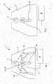
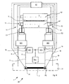
- a bending machine 1 of the four-roller type and a bending machine 10 of the two-roller type for working metal products, in particular for bending L-shaped sheet metal, metal profiled sections or other similar products.
- Both the bending machine 1 and the bending machine 10 each comprise a supporting frame 2 supporting one or more dragging rollers for the advancement of the piece of sheet metal L to be bent that are connected to respective reduction gears.
- a supporting frame 2 supporting one or more dragging rollers for the advancement of the piece of sheet metal L to be bent that are connected to respective reduction gears.
- FIGs 1 and 2 for the sake of simplicity, there is shown only one dragging roller 3.
- a movable roller 4 for pinching the piece of sheet metal L, the movable roller 4 being configured for being brought near, and moved away from the aforesaid dragging roller 3.
- the movable roller 4 is supported by hydraulic actuators C1, C2, of the dual-effect type, that are drivable for raising and lowering the movable roller 4.
- respective slides 50 are provided that are arranged for guiding the ascent and descent movement of the movable roller 4.
- the dragging roller 3, in a non-limiting manner, can be supported by an overturnable arm that enables a workpiece to be removed once it has been bent.
- the bending machine 1 is further provided with a first 30 and a second 31 idle roller supported by respective oscillating arms pivoted on side pivots.
- the aforesaid bending machines 1 and 10 represent two possible apparatuses in which a control apparatus 20 according to the invention, which will be disclosed below, can be incorporated and which is used to vary the tilt of the or of each movable roller, for example to correct bending defects or to make conical bends, whilst maintaining always control of the parallelism of the roller with respect to the axis thereof or according to a preset axis.
- control apparatus 20 which will be disclosed in detail below- can be applied for controlling parallelism both in bending machines with rollers that are movable along linear guides and vertical or horizontal axes and in bending machines provided with rollers moving along planetary guides or supported by oscillating arms pivoted on side pivots.
- control apparatus 20 is configured for controlling the parallelism of the only movable roller 4, in the bending machine 1 or 10 shown In Figures 1 and 2 .
- parallelism control can also be applied to several or all the moving rollers of a bending machine, providing several respective control apparatuses 20 or a single control apparatus 20 that is suitably configured for controlling all the aforesaid moving rollers.
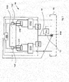
- a first hydraulic actuator C1 and a second hydraulic actuator C2 are provided respectively for moving the movable roller 4 towards or away from the dragging roller 3.
- the first C1 and second C2 hydraulic actuator are suppliable with an operating fluid, in particular oil, each by a respective pump and a dedicated hydraulic circuit.
- the first C1 and the second C2 hydraulic actuator are suppliable respectively with a first pump P1 and a second pump P2, through a first hydraulic circuit 5 and a second hydraulic circuit 6 that are independent of one another.
- the first pump P1 and the second pump P2 are operationally connected to one another.
- first pump P1 and the second pump P2 are substantially similar to one another, of the same volumetric flowrate, and are mechanically connected to one another via a mechanical transmission shaft 7 as can be seen in schematised form in Figure 4 .
- the mechanical transmission shaft 7 that is common to the first P1 and to the second pump P2 is arranged for synchronising the motion of the two aforesaid pumps at the same rotation speed, such as to supply the same oil volumetric flowrate values to the first C1 and second C2 hydraulic actuator.
- dispensing of identical quantities of oil to the first C1 and second C2 hydraulic actuator is ensured.
- the first hydraulic circuit 5 comprises a first delivery portion 8 that connects the first pump P1 to a first directional valve VD1.
- the first directional valve VD1 is connected by two connecting conduits to two respective fluid dynamic chambers of the first hydraulic actuator C1.
- the first directional valve VD1 acts to control the flow direction of the oil inside the first hydraulic actuator C1, such as to fill one chamber by emptying the other, depending on whether the first end 11 of the movable roller 4 has to be moved towards or away from the dragging roller 3.
- the first hydraulic circuit 5 further comprises a first return portion 9 through which the oil that is evacuated from the first hydraulic actuator C1, passing through the first directional valve VD1, returns to a collecting and storage tank 21.
- the second hydraulic circuit 6 comprises a second delivery portion 18 that connects the second pump P2 to a second directional valve VD2, that has a function that is similar to what has been disclosed for the first directional valve VD1.
- the second directional valve VD2 is connected by two further connecting conduits to two respective further fluid dynamic chambers of the second hydraulic actuator C2.
- the second hydraulic circuit 6 comprises a second return portion 19 through which the oil that is evacuated from the second hydraulic actuator C2, passing through the second directional valve VD2, returns to the oil collecting and storage tank 21.
- the control apparatus 20 comprises a first proportional flow valve VP1 and a second proportional valve VP2, associated respectively with the first hydraulic circuit 5 and with the second hydraulic circuit 6.
- the first proportional flow valve VP1 and the second proportional valve VP2 are connected according to a parallel configuration with respect to the first delivery portion 8 and to the second delivery portion 18. More precisely, the first proportional flow valve VP1 is placed along a first branch conduit 13 connected, in derivation, to the first delivery conduit 8 and extending as far as the tank 21.
- the second proportional valve VP2 is placed along a second branch conduit 14, connected, in derivation, to the second delivery conduit 18 and extending as far as the tank 21.
- the first VP1 and second VP2 proportional valve which are so positioned, are configured for being able to tap, i.e. draw, the oil respectively from the first 8 and second 18 delivery portion to reduce the volumetric flowrate of oil that flows respectively to the first C1 and second C2 hydraulic actuator.
- the first VP1 and second VP2 proportional valve - which are placed in a "derivation" position i.e. "branched” position with respect to the delivery paths of the oil - are positioned for operating "parallel" to the "work” flow of the oil.
- the parallelism control of electronic type obtained by acting on the first VP1 and second VP2 proportional valve, is an auxiliary or "additional" control to the inherent parallelism control already existing in the hydraulic circuit conformation of the control apparatus 20.
- a maximum pressure valve Vmax is also provided that is connected to the first 8 and second 18 delivery portion, the function of which is to deliver the circulating oil directly to the tank 21 if the pressure reaches a maximum set value, thus avoiding undesired damage to the bending machine.
- a first T1 and a second T2 position transducer are respectively provided.
- the first T1 and the second T2 position transducer are arranged for detecting the positions of said first 11 and second 12 end.
- the control apparatus 20 comprises an electronic control unit U1 to which the first VP1 and second VP2 proportional valve, the first VD1 and second VD2 directional valve, and the first T1 and second T2 position transducer are operationally connected.
- the first VP1 and second VP2 proportional valve are driven, in case of need, by the electronic control unit U1, on the basis of position signals produced by the first T1 and second T2 position transducer, such as to regulate the oil volumetric flowrate that advances to the first C1 and second C2 hydraulic actuator.
- the electronic control unit U1 is able to check the parallelism of the movable roller 4, or of each movable roller, of the bending machine 1 or 10 through position signals that are provided by the position transducers T1 and T2 and are compared by an analogue comparing unit, which in turn supplies instructions to a logical processing unit (PLC).
- the logical processing unit (PLC) comprises a suitably programmed microprocessor for automatically correcting possible parallelism errors by commanding the first VP1 and/or second VP2 proportional valve, or solenoid valves, for supplying the pressurised oil to the hydraulic actuators C1, C2 for the translation movement of the roller.
- the proportional valves or solenoid valves VP1, VP2, are activatable by respective driving solenoids by means of suitable electric pulses or signals.
- the first T1 and second T2 position transducer can each comprise a linear potentiometric transducer that sends the position signals to a respective input of the control unit U1, which compares it with programmed reference data and then sends suitable instructions to the microprocessor, such as to intervene, if required, on the tilt of the movable roller 4.
- first pump P1 and the second pump P2 can be connected operationally to the electronic control unit U1, which controls all the various steps of a work cycle.
- the electronic control unit U1 commands the first VD1 and second VD2 directional valve in such a manner that the oil flow in the first C1 and in the second C2 hydraulic actuator is enabled in an advancement direction or in an opposite direction, depending on whether the movable roller 4 has to be moved towards or away from the dragging roller 3.
- the first VD1 and second VD2 directional valve are driven by the electronic control unit U1 to lower or raise the movable roller 4.
- first VP1 and second VP2 proportional valve are "normally closed", i.e. they are not traversed by a flow of oil, which oil thus advances undisturbed along respectively the first 8 and second 18 delivery portion with identical volumetric flowrate values both in the first 5 and in the second 6 hydraulic circuit, thus ensuring perfectly balanced driving of the first C1 and second C2 hydraulic actuator.
- first VP1 and second VP2 proportional valve are "normally closed", i.e. they are not traversed by a flow of oil, which oil thus advances undisturbed along respectively the first 8 and second 18 delivery portion with identical volumetric flowrate values both in the first 5 and in the second 6 hydraulic circuit, thus ensuring perfectly balanced driving of the first C1 and second C2 hydraulic actuator.
- a first control level, of hydraulic type, of the parallelism is defined that guarantees, with a satisfactory degree of precision, the parallelism of the movable roller 4, more precisely, the parallelism of a first longitudinal axis A1 of the movable roller 4 with respect to a second longitudinal axis A2 of the dragging roller 3, during raising or lowering, also in a non-centred loading operating situation, i.e. with a load acting near the first 11 or the second 12 end.
- the piece of sheet metal L is appropriately bent by the interaction with the movable roller 4 and with the dragging roller 3, without the first VP1 and second VP2 proportional valve intervening, which remain "normally closed".
- the parallelism condition is maintained through the effect of the hydraulic control level that derives from the particular hydraulic supply that is split and balanced in relation to the two hydraulic actuators C1 and C2.
- the control unit U1 intervenes to open the first VP1 and/or second VP2 proportional valve.
- a second control level of electronic type thus intervenes, which is servo- assisted by the first hydraulic control level disclosed above, but is independent thereof.
- the first proportional flow valve VP1 is opened (and not closed as would occur in a prior-art apparatus), to enable a calibrated passage of the derived oil, i.e. of the oil tapped, i.e. drawn, parallely from the first delivery portion 8, to the tank 21.
- the first hydraulic actuator C1 instead of continuing to advance to the first hydraulic actuator C1, is discharged freely (and thus at the working pressure of the piece of sheet metal L and not at maximum pressure as would occur in the prior-art apparatus) to the tank 21.
- This means that a smaller amount of oil reaches the first hydraulic actuator C1, thus slowing the first hydraulic actuator C1 and adapting the position and advancement speed thereof to those of the second hydraulic actuator C2.
- the first C1 and second C2 hydraulic actuator can continue advancement perfectly synchronised with one another.
- the control of the parallelism of the movable roller 4 can be carried out indifferently both during the ascent and the descent movement of the movable roller 4.
- the first VP1 and second VP2 proportional valves are thus not fatigued and are driven only when strictly necessary, i.e. with reduced frequency compared with what occurs in the prior art, as the parallelism is maintained in most of the operating circumstances by the hydraulic control level inherent to the hydraulic structural conformation of the control apparatus 20.
- Both the proportional valves VP1, VP2 and the first P1 and second pump P2 and all the other components of the apparatus operate subject to a pressure that is the one requested by the working of the piece of sheet metal L, and never at a higher pressure, this resulting in an extension to the working life of the hydraulic componentry of the bending machine.
- the bending machine in all cases, even in the event of a fault to an electronic component, the bending machine, owing to the control apparatus 20, can continue to be used without causing machine downtime, in normal operating circumstances in which exceptional load conditions do not occur or in which no commanded variation is required of the tilt of the first longitudinal axis A1 with respect to the second longitudinal axis A2, for example for conical bending of the sheet metal, or for bending section bars, made on the outside of the rollers, on apposite shaping portions protruding from the latter.
- control apparatus 20 including a first control level of hydraulic type, and a second control level of electronic type, make the bending machine 1 or 10 more reliable and efficient, drastically reducing machine downtime risks.
Landscapes
- Engineering & Computer Science (AREA)
- Mechanical Engineering (AREA)
- Physics & Mathematics (AREA)
- Fluid Mechanics (AREA)
- General Engineering & Computer Science (AREA)
- Bending Of Plates, Rods, And Pipes (AREA)
- Soft Magnetic Materials (AREA)
Claims (11)
- Vorrichtung zur elektrohydraulischen Steuerung der Parallelität einer Walze (4) einer Biegemaschine (1; 10) zur Bearbeitung von Metallstücken (L), umfassend:ein Pumpenmittel (P1, P2), um ein erstes Betätigungsmittel (C1) und ein zweites Betätigungsmittel (C2), die zum jeweiligen Bewegen eines ersten Endes (11) und eines zweiten Endes (12) der Walze (4) eingerichtet sind, mit einem Betriebsfluid zu versorgen;ein Positionsumwandlermittel (T1, T2), das betrieblich mit einer elektronischen Steuereinheit (U1) verbunden ist und dazu geeignet ist, die Positionen des ersten (11) und des zweiten (12) Endes festzustellen;wobei das Pumpenmittel eine erste Pumpe (P1) und eine zweite Pumpe (P2) umfasst, die betrieblich miteinander verbunden sind, und eingerichtet sind, um das erste (C1) bzw. das zweite (C2) Betätigungsmittel durch einen ersten (5) und einen zweiten (6) Hydraulikkreis, die voneinander unabhängig sind, auf eine zweckbestimmte Weise zu versorgen,dadurch gekennzeichnet, dassdie Vorrichtung ein erstes (VP1) und ein zweites (VP2) Proportionalventilmittel umfasst, die betrieblich so durch die elektronische Steuereinheit (U1) gesteuert werden können, dass der Strom des Betriebsfluids in das erste (C1) und das zweite (C2) Betätigungsmittel gemäß Signalen des Positionsumwandlermittels (T1, T2) reguliert wird,wobei das erste (VP1) und das zweite (VP2) Proportionalventilmittel gemäß einer parallelen Anordnung entlang einer ersten (13) und einer zweiten (14) Leitung angeordnet sind, die auf eine verzweigte Weise mit einem ersten (8) und einem zweiten (18) Zufuhrabschnitt des ersten (5) bzw. des zweiten (6) Hydraulikkreises verbunden sind, wobei das erste (VP1) und das zweite (VP2) Proportionalventilmittel so gestaltet sind, dass sie fähig sind, Betriebsfluid von dem ersten (8) und dem zweiten (18) Zufuhrabschnitt abzuziehen, um deren volumetrischen Durchfluss zu dem ersten (C1) und/oder zweiten (C2) Betätigungsmittel zu verringern.
- Vorrichtung nach Anspruch 1, wobei die erste Pumpe (P1) und die zweite Pumpe (P2) durch eine gemeinsame mechanische Übertragungswelle (7), die eingerichtet ist, um die Bewegung der ersten Pumpe (P1) und der zweiten Pumpe (P2) auf die gleiche Umdrehungsgeschwindigkeit zu synchronisieren, um dem ersten (C1) und dem zweiten (C2) Betätigungsmittel die gleichen volumetrischen Betriebsfluid-Durchflusswerte bereitzustellen, mechanisch miteinander verbunden sind.
- Vorrichtung nach Anspruch 1 oder 2, ferner umfassend ein erstes (VD1) und ein zweites (VD2) Wegeventil, die in dem ersten (5) bzw. zweiten (6) Kreis bereitgestellt sind, um die Flussrichtung des Betriebsfluids in Bezug auf das erste (C1) und das zweite (C2) Betätigungsmittel zu regulieren.
- Vorrichtung nach einem der Ansprüche 1 bis 3, wobei sich eine erste (13) und eine zweite (14) Zweigleitung auf eine solche Weise erstrecken, dass das von dem ersten (VP1) und dem zweiten (VP2) Proportionalventil einlangende Betriebsfluid dazu gebracht wird, in einen Tank (21), der den ersten (5) und den zweiten (6) Hydraulikkreis versorgt, zu fließen.
- Vorrichtung nach Anspruch 4, wobei die erste Pumpe (P1) und die zweite Pumpe (P2) mit einem Höchstdruckventil (Vmax) verbunden sind, das das Betriebsfluid in das Innere des Tanks (21) ablässt, wenn ein festgelegter Höchstdruckwert erreicht wird.
- Biegemaschine zur Bearbeitung von Metallprodukten wie Blechen oder Profilstangen, umfassend zwei oder mehr Biegewalzen (3, 4; 3, 4, 30, 31) und eine Vorrichtung (20) zur Steuerung der Parallelität nach einem der vorhergehenden Ansprüche, die eingerichtet ist, um die Parallelität wenigstens einer der zwei oder mehr Biegewalzen (3, 4; 3, 4, 30, 31) zu steuern.
- Verfahren zur elektrohydraulischen Steuerung der Parallelität einer Walze (4) einer Biegemaschine (1; 10) zur Bearbeitung von Metallstücken (L), umfassend die folgenden Schritte:Versorgen eines ersten Betätigungsmittels (C1) und eines zweiten Betätigungsmittels (C2) mit einem Betriebsfluid, damit diese jeweils ein erstes Ende (11) und ein zweites Ende (12) der Walze (4) bewegen;Feststellen und elektronisches Verarbeiten von Positionssignalen des ersten (11) und des zweiten (12) Endes, um den Parallelitätszustand der Walze (4) zu prüfen;wobei das Versorgen ein derartiges Pumpen des Betriebsfluids durch eine erste Pumpe (P1) und eine zweite Pumpe (P2), die betrieblich miteinander verbunden sind, umfasst, dass das erste (C1) bzw. das zweite Betätigungsmittel (C2) durch einen ersten (5) und einen zweiten (6) Hydraulikkreis, die voneinander unabhängig sind, auf eine zweckbestimmte Weise versorgt werden,dadurch gekennzeichnet, dass das Verfahren ein Steuern des Stroms des Betriebsfluids in dem ersten (C1) und dem zweiten (C2) Betätigungsmittel durch Einwirken auf ein erstes (VP1) und ein zweites (VP2) Proportionalventilmittel als Funktion der Positionssignale umfasst,wobei das Steuern umfasst, dass das erste (VP1) und das zweite (VP2) Proportionalventilmittel geöffnet werden, um das Betriebsfluid durch eine erste (13) und eine zweite (14) Leitung, die auf eine verzweigte Weise mit einem ersten (8) und einem zweiten (18) Zufuhrabschnitt des ersten (5) bzw. zweiten (6) Hydraulikkreises verbunden sind, abzuziehen, wodurch der volumetrische Durchfluss des Betriebsfluids zu dem ersten (C1) und/oder zweiten (C2) Betätigungsmittel verringert wird.
- Verfahren nach Anspruch 7, wobei das Pumpen umfasst, dass die Bewegung der ersten Pumpe (P1) und der zweiten Pumpe (P2) auf die gleiche Umdrehungsgeschwindigkeit synchronisiert gehalten wird, um dem ersten (C1) und dem zweiten (C2) Betätigungsmittel die gleichen volumetrischen Betriebsfluid-Durchflusswerte bereitzustellen.
- Verfahren nach Anspruch 7 oder 8, ferner umfassend das Antreiben eines ersten (VD1) und eines zweiten (VD2) Wegeventilmittels, um die Flussrichtung in dem ersten (C1) und dem zweiten (C2) Betätigungsmittel zu regulieren.
- Verfahren nach einem der Ansprüche 7 bis 9, wobei das Abziehen umfasst, dass das Betriebsfluid dazu gebracht wird, bei dem Arbeitsdruck, der zum Biegen des Werkstücks (L) ausgeübt wird, frei in einen Tank (21) für das Fluid zu fließen.
- Verfahren nach Anspruch 10, wobei ein Ablassen des Betriebsfluids durch ein Höchstdruckventil (Vmax) in den Tank (21), wenn ein bestimmter Höchstdruckwert erreicht wird, bereitgestellt ist.
Priority Applications (1)
| Application Number | Priority Date | Filing Date | Title |
|---|---|---|---|
| PL12177973T PL2551029T3 (pl) | 2011-07-27 | 2012-07-26 | Urządzenie i sposób elektrohydraulicznego sterowania równoległością w giętarce do obróbki metalowych wyrobów |
Applications Claiming Priority (1)
| Application Number | Priority Date | Filing Date | Title |
|---|---|---|---|
| IT001408A ITMI20111408A1 (it) | 2011-07-27 | 2011-07-27 | Apparato e metodo per il controllo elettroidraulico del parallelismo in una calandra per la lavorazione di manufatti in metallo |
Publications (2)
| Publication Number | Publication Date |
|---|---|
| EP2551029A1 EP2551029A1 (de) | 2013-01-30 |
| EP2551029B1 true EP2551029B1 (de) | 2014-03-12 |
Family
ID=44545833
Family Applications (1)
| Application Number | Title | Priority Date | Filing Date |
|---|---|---|---|
| EP12177973.0A Active EP2551029B1 (de) | 2011-07-27 | 2012-07-26 | Vorrichtung und Verfahren zur elektrohydraulischen Steuerung der Parallelität in einer Biegemaschine zur Bearbeitung von Metallprodukten |
Country Status (7)
| Country | Link |
|---|---|
| US (2) | US9468961B2 (de) |
| EP (1) | EP2551029B1 (de) |
| DK (1) | DK2551029T3 (de) |
| ES (1) | ES2519265T3 (de) |
| IT (1) | ITMI20111408A1 (de) |
| PL (1) | PL2551029T3 (de) |
| PT (1) | PT2551029E (de) |
Families Citing this family (17)
| Publication number | Priority date | Publication date | Assignee | Title |
|---|---|---|---|---|
| ITMI20111408A1 (it) * | 2011-07-27 | 2013-01-28 | Promau Srl | Apparato e metodo per il controllo elettroidraulico del parallelismo in una calandra per la lavorazione di manufatti in metallo |
| RU2534649C1 (ru) * | 2013-05-06 | 2014-12-10 | Эмерсон Процесс Менеджмент Пауэр Энд Вотер Солюшнз, Инк. | Система управления кольцевым затвором (варианты) и способ управления кольцевым затвором |
| CN103334973B (zh) * | 2013-06-13 | 2016-01-20 | 三一汽车起重机械有限公司 | 一种多液压缸同步系统及多液压缸同步系统的控制方法 |
| CN104454748B (zh) * | 2014-12-05 | 2017-01-25 | 宁波恒力液压股份有限公司 | 齿轮泵、溢流阀及单向阀可靠性的综合节能试验液压装置 |
| CN104959406A (zh) * | 2015-06-22 | 2015-10-07 | 苏州边桐传感科技有限公司 | 带角度调控与阶段折弯的钣金折弯系统 |
| CN104959408A (zh) * | 2015-06-22 | 2015-10-07 | 苏州边桐传感科技有限公司 | 钣金折弯加工装置 |
| CN104942077A (zh) * | 2015-06-25 | 2015-09-30 | 苏州边桐传感科技有限公司 | 带厚度检测调整与压力检测的折弯装置及方法 |
| CN104942072A (zh) * | 2015-06-25 | 2015-09-30 | 苏州边桐传感科技有限公司 | 带自动扭矩调节与滚压折弯的折弯装置及方法 |
| CN104942080A (zh) * | 2015-06-25 | 2015-09-30 | 苏州边桐传感科技有限公司 | 钣金折弯加工装置及方法 |
| CN105909575B (zh) * | 2016-06-28 | 2017-10-31 | 安徽东海机床制造有限公司 | 一种高效折弯机的折弯方法 |
| CN106140980B (zh) * | 2016-08-22 | 2018-03-02 | 仪征雄伟机械科技有限公司 | 一种数字化显示弯曲冲模装置 |
| US10512961B2 (en) * | 2016-11-11 | 2019-12-24 | Mega Manufacturing, Inc. | Plate roll bending machine with distributed hydraulic system |
| DE102017217715A1 (de) * | 2017-10-05 | 2019-04-11 | Peri Gmbh | Hydraulik-Anordnung mit vernetzten Hydraulikaggregaten sowie Kletterschalung und Verfahren zum Bewegen der Kletterschalung mit einer solchen Hydraulik-Anordnung |
| US11219933B2 (en) * | 2017-11-10 | 2022-01-11 | Promau S.R.L. | Apparatus and method for support and controlled advancement of a metal sheet in a bending machine for obtaining cylindrical or truncated cone structures |
| CN109663840B (zh) * | 2019-01-29 | 2023-07-04 | 南通泰胜蓝岛海洋工程有限公司 | 一种三辊卷板机的控制系统 |
| IT202300001590A1 (it) * | 2023-02-01 | 2024-08-01 | Promau Srl | Macchina piegatrice a rulli |
| CN120023210B (zh) * | 2025-04-23 | 2025-07-08 | 山西万流金属制品有限公司 | 一种可变直径的金属板卷绕制管装置 |
Family Cites Families (11)
| Publication number | Priority date | Publication date | Assignee | Title |
|---|---|---|---|---|
| GB1083138A (en) * | 1963-10-07 | 1967-09-13 | United Eng Foundry Co | Pressure and control device for a rolling mill |
| EP0103727A1 (de) * | 1982-09-02 | 1984-03-28 | Inventio Ag | Gleichlaufregelungseinrichtung für den elektrohydraulischen Antrieb einer Abkantpresse |
| JPS59225821A (ja) * | 1983-06-06 | 1984-12-18 | Fuji Sharyo Kk | 油圧シリンダ駆動機構における制御装置 |
| RU1774889C (ru) * | 1990-08-20 | 1992-11-07 | А. И. Батров | Гидросистема синхронизации гидроцилиндров |
| IT223460Z2 (it) * | 1990-09-28 | 1995-07-19 | Davi Spa | Calandra curvatrice a 4 rulli sagomatori con supporti antiflessione longitudinali e seie di rullini di contrasto. |
| DE69108497T2 (de) * | 1990-09-28 | 1995-12-14 | Promau Srl | Programmierbare Blechbiegemaschine. |
| IT1289355B1 (it) * | 1996-12-18 | 1998-10-02 | Promau Srl | Procedimento per la curvatura di lamiere,e relativa calandra |
| IT1296576B1 (it) * | 1997-11-27 | 1999-07-14 | Promau Srl | Apparecchiatura automatica per la curvatura di lamiere, con controllo selettivo digitale |
| US6240758B1 (en) * | 1999-06-21 | 2001-06-05 | Toyokoki Co., Ltd. | Hydraulic machine |
| KR100915207B1 (ko) * | 2007-10-16 | 2009-09-02 | 볼보 컨스트럭션 이키프먼트 홀딩 스웨덴 에이비 | 중장비용 유압회로 |
| ITMI20111408A1 (it) * | 2011-07-27 | 2013-01-28 | Promau Srl | Apparato e metodo per il controllo elettroidraulico del parallelismo in una calandra per la lavorazione di manufatti in metallo |
-
2011
- 2011-07-27 IT IT001408A patent/ITMI20111408A1/it unknown
-
2012
- 2012-07-25 US US13/557,513 patent/US9468961B2/en active Active
- 2012-07-26 ES ES12177973.0T patent/ES2519265T3/es active Active
- 2012-07-26 PT PT121779730T patent/PT2551029E/pt unknown
- 2012-07-26 PL PL12177973T patent/PL2551029T3/pl unknown
- 2012-07-26 EP EP12177973.0A patent/EP2551029B1/de active Active
- 2012-07-26 DK DK12177973.0T patent/DK2551029T3/da active
-
2016
- 2016-09-22 US US15/273,253 patent/US9669443B2/en active Active
Also Published As
| Publication number | Publication date |
|---|---|
| US20130025335A1 (en) | 2013-01-31 |
| ITMI20111408A1 (it) | 2013-01-28 |
| US9468961B2 (en) | 2016-10-18 |
| ES2519265T3 (es) | 2014-11-06 |
| PL2551029T3 (pl) | 2014-09-30 |
| DK2551029T3 (da) | 2014-06-16 |
| US9669443B2 (en) | 2017-06-06 |
| EP2551029A1 (de) | 2013-01-30 |
| US20170008056A1 (en) | 2017-01-12 |
| PT2551029E (pt) | 2014-06-23 |
Similar Documents
| Publication | Publication Date | Title |
|---|---|---|
| EP2551029B1 (de) | Vorrichtung und Verfahren zur elektrohydraulischen Steuerung der Parallelität in einer Biegemaschine zur Bearbeitung von Metallprodukten | |
| EP2174002B1 (de) | Wandler und verfahren zum wandeln von mechanischer energie in elektrische energie | |
| EP2121280B1 (de) | Elektrohydraulische steueranordnung | |
| EP3601805B1 (de) | Vorrichtung zum regeln einer hydraulischen maschine | |
| DE19538649A1 (de) | Leistungsregelung mit Load-Sensing | |
| EP2729263B9 (de) | Vorrichtung für treibwalzen | |
| EP3601806B1 (de) | Vorrichtung zum regeln einer hydraulischen maschine | |
| AT516316B1 (de) | Verfahren zur Steuerung einer hydraulisch angetriebenen Maschine | |
| DE102012019665B4 (de) | Hydraulische Steueranordnung und Presse mit einer derartigen Steueranordnung | |
| JP2005042916A5 (de) | ||
| EP2895743A1 (de) | Vorrichtung zur antriebssteuerung einer zweizylinder-dickstoffpumpe | |
| AT515590A1 (de) | Dynamischer Sollwertausgleich bei drehzahlvariablen Verstellpumpen | |
| CN104428077B (zh) | 液压挤压机和用于操作液压挤压机的方法 | |
| CN202579384U (zh) | 基于比例阀控蓄能器调节偏载的液压同步驱动系统 | |
| EP3988801B1 (de) | Verfahren zum betreiben eines hydraulischen antriebs | |
| EP3170608A2 (de) | Schweisskappen-kühlwassersteuerung | |
| EP2808109B1 (de) | Spannsystem | |
| DE102017003963A1 (de) | Hydraulische, insbesondere druckspeicherlose, Antriebsanordnung für und mit einem Verbraucher, insbesondere für Pressen, sowie Verfahren zum Betreiben einer hydraulischen Antriebsanordnung | |
| DE102008038381B4 (de) | Hydrostatisches Antriebssystem | |
| EP2121227B1 (de) | Fluidverteilervorrichtung und stanzverfahren | |
| JP6015440B2 (ja) | 材料試験機 | |
| DE102022129473A1 (de) | Mobile Arbeitsmaschine, insbesondere Flurförderzeug | |
| JP7839397B2 (ja) | 油圧装置 | |
| CN1250355C (zh) | 能量扩散减小的高性能弯折机 | |
| KR20250134123A (ko) | 롤 벤딩 머신 |
Legal Events
| Date | Code | Title | Description |
|---|---|---|---|
| PUAI | Public reference made under article 153(3) epc to a published international application that has entered the european phase |
Free format text: ORIGINAL CODE: 0009012 |
|
| AK | Designated contracting states |
Kind code of ref document: A1 Designated state(s): AL AT BE BG CH CY CZ DE DK EE ES FI FR GB GR HR HU IE IS IT LI LT LU LV MC MK MT NL NO PL PT RO RS SE SI SK SM TR |
|
| AX | Request for extension of the european patent |
Extension state: BA ME |
|
| 17P | Request for examination filed |
Effective date: 20130726 |
|
| RBV | Designated contracting states (corrected) |
Designated state(s): AL AT BE BG CH CY CZ DE DK EE ES FI FR GB GR HR HU IE IS IT LI LT LU LV MC MK MT NL NO PL PT RO RS SE SI SK SM TR |
|
| GRAP | Despatch of communication of intention to grant a patent |
Free format text: ORIGINAL CODE: EPIDOSNIGR1 |
|
| RIC1 | Information provided on ipc code assigned before grant |
Ipc: B21D 5/14 20060101AFI20130826BHEP Ipc: F15B 11/17 20060101ALI20130826BHEP Ipc: F15B 11/22 20060101ALI20130826BHEP |
|
| INTG | Intention to grant announced |
Effective date: 20130911 |
|
| GRAS | Grant fee paid |
Free format text: ORIGINAL CODE: EPIDOSNIGR3 |
|
| GRAA | (expected) grant |
Free format text: ORIGINAL CODE: 0009210 |
|
| AK | Designated contracting states |
Kind code of ref document: B1 Designated state(s): AL AT BE BG CH CY CZ DE DK EE ES FI FR GB GR HR HU IE IS IT LI LT LU LV MC MK MT NL NO PL PT RO RS SE SI SK SM TR |
|
| REG | Reference to a national code |
Ref country code: GB Ref legal event code: FG4D |
|
| REG | Reference to a national code |
Ref country code: CH Ref legal event code: EP |
|
| REG | Reference to a national code |
Ref country code: AT Ref legal event code: REF Ref document number: 655888 Country of ref document: AT Kind code of ref document: T Effective date: 20140315 |
|
| REG | Reference to a national code |
Ref country code: IE Ref legal event code: FG4D |
|
| REG | Reference to a national code |
Ref country code: DE Ref legal event code: R096 Ref document number: 602012001012 Country of ref document: DE Effective date: 20140424 |
|
| REG | Reference to a national code |
Ref country code: CH Ref legal event code: PCOW Free format text: NEW ADDRESS: C/O COLOBERTI & LUPPI SRL VIA CIVINELLI 1150, 47522 CESENA (FC) (IT) Ref country code: CH Ref legal event code: PCOW Free format text: NEW ADDRESS: C/O COLOBERTI & LUPPI SRL VIA E. DE AMICIS 25, 20123 MILANO (IT) |
|
| REG | Reference to a national code |
Ref country code: DK Ref legal event code: T3 Effective date: 20140613 |
|
| REG | Reference to a national code |
Ref country code: NL Ref legal event code: T3 |
|
| REG | Reference to a national code |
Ref country code: PT Ref legal event code: SC4A Free format text: AVAILABILITY OF NATIONAL TRANSLATION Effective date: 20140606 |
|
| REG | Reference to a national code |
Ref country code: SE Ref legal event code: TRGR |
|
| PG25 | Lapsed in a contracting state [announced via postgrant information from national office to epo] |
Ref country code: NO Free format text: LAPSE BECAUSE OF FAILURE TO SUBMIT A TRANSLATION OF THE DESCRIPTION OR TO PAY THE FEE WITHIN THE PRESCRIBED TIME-LIMIT Effective date: 20140612 Ref country code: LT Free format text: LAPSE BECAUSE OF FAILURE TO SUBMIT A TRANSLATION OF THE DESCRIPTION OR TO PAY THE FEE WITHIN THE PRESCRIBED TIME-LIMIT Effective date: 20140312 |
|
| REG | Reference to a national code |
Ref country code: AT Ref legal event code: MK05 Ref document number: 655888 Country of ref document: AT Kind code of ref document: T Effective date: 20140312 |
|
| REG | Reference to a national code |
Ref country code: LT Ref legal event code: MG4D |
|
| PG25 | Lapsed in a contracting state [announced via postgrant information from national office to epo] |
Ref country code: FI Free format text: LAPSE BECAUSE OF FAILURE TO SUBMIT A TRANSLATION OF THE DESCRIPTION OR TO PAY THE FEE WITHIN THE PRESCRIBED TIME-LIMIT Effective date: 20140312 Ref country code: CY Free format text: LAPSE BECAUSE OF FAILURE TO SUBMIT A TRANSLATION OF THE DESCRIPTION OR TO PAY THE FEE WITHIN THE PRESCRIBED TIME-LIMIT Effective date: 20140312 |
|
| PG25 | Lapsed in a contracting state [announced via postgrant information from national office to epo] |
Ref country code: HR Free format text: LAPSE BECAUSE OF FAILURE TO SUBMIT A TRANSLATION OF THE DESCRIPTION OR TO PAY THE FEE WITHIN THE PRESCRIBED TIME-LIMIT Effective date: 20140312 Ref country code: LV Free format text: LAPSE BECAUSE OF FAILURE TO SUBMIT A TRANSLATION OF THE DESCRIPTION OR TO PAY THE FEE WITHIN THE PRESCRIBED TIME-LIMIT Effective date: 20140312 Ref country code: RS Free format text: LAPSE BECAUSE OF FAILURE TO SUBMIT A TRANSLATION OF THE DESCRIPTION OR TO PAY THE FEE WITHIN THE PRESCRIBED TIME-LIMIT Effective date: 20140312 |
|
| REG | Reference to a national code |
Ref country code: PL Ref legal event code: T3 |
|
| PG25 | Lapsed in a contracting state [announced via postgrant information from national office to epo] |
Ref country code: IS Free format text: LAPSE BECAUSE OF FAILURE TO SUBMIT A TRANSLATION OF THE DESCRIPTION OR TO PAY THE FEE WITHIN THE PRESCRIBED TIME-LIMIT Effective date: 20140712 Ref country code: BG Free format text: LAPSE BECAUSE OF FAILURE TO SUBMIT A TRANSLATION OF THE DESCRIPTION OR TO PAY THE FEE WITHIN THE PRESCRIBED TIME-LIMIT Effective date: 20140612 Ref country code: EE Free format text: LAPSE BECAUSE OF FAILURE TO SUBMIT A TRANSLATION OF THE DESCRIPTION OR TO PAY THE FEE WITHIN THE PRESCRIBED TIME-LIMIT Effective date: 20140312 Ref country code: BE Free format text: LAPSE BECAUSE OF FAILURE TO SUBMIT A TRANSLATION OF THE DESCRIPTION OR TO PAY THE FEE WITHIN THE PRESCRIBED TIME-LIMIT Effective date: 20140312 Ref country code: CZ Free format text: LAPSE BECAUSE OF FAILURE TO SUBMIT A TRANSLATION OF THE DESCRIPTION OR TO PAY THE FEE WITHIN THE PRESCRIBED TIME-LIMIT Effective date: 20140312 Ref country code: RO Free format text: LAPSE BECAUSE OF FAILURE TO SUBMIT A TRANSLATION OF THE DESCRIPTION OR TO PAY THE FEE WITHIN THE PRESCRIBED TIME-LIMIT Effective date: 20140312 |
|
| REG | Reference to a national code |
Ref country code: ES Ref legal event code: FG2A Ref document number: 2519265 Country of ref document: ES Kind code of ref document: T3 Effective date: 20141106 |
|
| PG25 | Lapsed in a contracting state [announced via postgrant information from national office to epo] |
Ref country code: AT Free format text: LAPSE BECAUSE OF FAILURE TO SUBMIT A TRANSLATION OF THE DESCRIPTION OR TO PAY THE FEE WITHIN THE PRESCRIBED TIME-LIMIT Effective date: 20140312 Ref country code: SK Free format text: LAPSE BECAUSE OF FAILURE TO SUBMIT A TRANSLATION OF THE DESCRIPTION OR TO PAY THE FEE WITHIN THE PRESCRIBED TIME-LIMIT Effective date: 20140312 |
|
| REG | Reference to a national code |
Ref country code: DE Ref legal event code: R097 Ref document number: 602012001012 Country of ref document: DE |
|
| PLBE | No opposition filed within time limit |
Free format text: ORIGINAL CODE: 0009261 |
|
| STAA | Information on the status of an ep patent application or granted ep patent |
Free format text: STATUS: NO OPPOSITION FILED WITHIN TIME LIMIT |
|
| 26N | No opposition filed |
Effective date: 20141215 |
|
| PG25 | Lapsed in a contracting state [announced via postgrant information from national office to epo] |
Ref country code: RS Free format text: LAPSE BECAUSE OF FAILURE TO SUBMIT A TRANSLATION OF THE DESCRIPTION OR TO PAY THE FEE WITHIN THE PRESCRIBED TIME-LIMIT Effective date: 20140903 |
|
| REG | Reference to a national code |
Ref country code: DE Ref legal event code: R097 Ref document number: 602012001012 Country of ref document: DE Effective date: 20141215 |
|
| REG | Reference to a national code |
Ref country code: IE Ref legal event code: MM4A |
|
| PG25 | Lapsed in a contracting state [announced via postgrant information from national office to epo] |
Ref country code: SI Free format text: LAPSE BECAUSE OF FAILURE TO SUBMIT A TRANSLATION OF THE DESCRIPTION OR TO PAY THE FEE WITHIN THE PRESCRIBED TIME-LIMIT Effective date: 20140312 |
|
| PG25 | Lapsed in a contracting state [announced via postgrant information from national office to epo] |
Ref country code: IE Free format text: LAPSE BECAUSE OF NON-PAYMENT OF DUE FEES Effective date: 20140726 |
|
| PGFP | Annual fee paid to national office [announced via postgrant information from national office to epo] |
Ref country code: LU Payment date: 20150723 Year of fee payment: 4 |
|
| PGFP | Annual fee paid to national office [announced via postgrant information from national office to epo] |
Ref country code: MC Payment date: 20150714 Year of fee payment: 4 |
|
| PG25 | Lapsed in a contracting state [announced via postgrant information from national office to epo] |
Ref country code: SM Free format text: LAPSE BECAUSE OF FAILURE TO SUBMIT A TRANSLATION OF THE DESCRIPTION OR TO PAY THE FEE WITHIN THE PRESCRIBED TIME-LIMIT Effective date: 20140312 |
|
| PG25 | Lapsed in a contracting state [announced via postgrant information from national office to epo] |
Ref country code: MT Free format text: LAPSE BECAUSE OF FAILURE TO SUBMIT A TRANSLATION OF THE DESCRIPTION OR TO PAY THE FEE WITHIN THE PRESCRIBED TIME-LIMIT Effective date: 20140312 Ref country code: GR Free format text: LAPSE BECAUSE OF FAILURE TO SUBMIT A TRANSLATION OF THE DESCRIPTION OR TO PAY THE FEE WITHIN THE PRESCRIBED TIME-LIMIT Effective date: 20140613 |
|
| REG | Reference to a national code |
Ref country code: FR Ref legal event code: PLFP Year of fee payment: 5 |
|
| PG25 | Lapsed in a contracting state [announced via postgrant information from national office to epo] |
Ref country code: HU Free format text: LAPSE BECAUSE OF FAILURE TO SUBMIT A TRANSLATION OF THE DESCRIPTION OR TO PAY THE FEE WITHIN THE PRESCRIBED TIME-LIMIT; INVALID AB INITIO Effective date: 20120726 |
|
| PG25 | Lapsed in a contracting state [announced via postgrant information from national office to epo] |
Ref country code: MC Free format text: LAPSE BECAUSE OF NON-PAYMENT OF DUE FEES Effective date: 20160801 |
|
| REG | Reference to a national code |
Ref country code: FR Ref legal event code: PLFP Year of fee payment: 6 |
|
| PG25 | Lapsed in a contracting state [announced via postgrant information from national office to epo] |
Ref country code: LU Free format text: LAPSE BECAUSE OF NON-PAYMENT OF DUE FEES Effective date: 20160726 |
|
| PG25 | Lapsed in a contracting state [announced via postgrant information from national office to epo] |
Ref country code: MK Free format text: LAPSE BECAUSE OF FAILURE TO SUBMIT A TRANSLATION OF THE DESCRIPTION OR TO PAY THE FEE WITHIN THE PRESCRIBED TIME-LIMIT Effective date: 20140312 |
|
| REG | Reference to a national code |
Ref country code: FR Ref legal event code: PLFP Year of fee payment: 7 |
|
| PG25 | Lapsed in a contracting state [announced via postgrant information from national office to epo] |
Ref country code: AL Free format text: LAPSE BECAUSE OF FAILURE TO SUBMIT A TRANSLATION OF THE DESCRIPTION OR TO PAY THE FEE WITHIN THE PRESCRIBED TIME-LIMIT Effective date: 20140312 |
|
| PGFP | Annual fee paid to national office [announced via postgrant information from national office to epo] |
Ref country code: FR Payment date: 20190726 Year of fee payment: 8 Ref country code: SE Payment date: 20190729 Year of fee payment: 8 Ref country code: ES Payment date: 20190801 Year of fee payment: 8 Ref country code: PT Payment date: 20190711 Year of fee payment: 8 Ref country code: TR Payment date: 20190708 Year of fee payment: 8 |
|
| PGFP | Annual fee paid to national office [announced via postgrant information from national office to epo] |
Ref country code: GB Payment date: 20190729 Year of fee payment: 8 |
|
| PGFP | Annual fee paid to national office [announced via postgrant information from national office to epo] |
Ref country code: CH Payment date: 20190801 Year of fee payment: 8 |
|
| REG | Reference to a national code |
Ref country code: DK Ref legal event code: EBP Effective date: 20190731 |
|
| PG25 | Lapsed in a contracting state [announced via postgrant information from national office to epo] |
Ref country code: NL Free format text: LAPSE BECAUSE OF NON-PAYMENT OF DUE FEES Effective date: 20190801 |
|
| REG | Reference to a national code |
Ref country code: NL Ref legal event code: MM Effective date: 20190801 |
|
| PG25 | Lapsed in a contracting state [announced via postgrant information from national office to epo] |
Ref country code: DK Free format text: LAPSE BECAUSE OF NON-PAYMENT OF DUE FEES Effective date: 20190731 |
|
| REG | Reference to a national code |
Ref country code: CH Ref legal event code: PL |
|
| REG | Reference to a national code |
Ref country code: SE Ref legal event code: EUG |
|
| GBPC | Gb: european patent ceased through non-payment of renewal fee |
Effective date: 20200726 |
|
| PG25 | Lapsed in a contracting state [announced via postgrant information from national office to epo] |
Ref country code: CH Free format text: LAPSE BECAUSE OF NON-PAYMENT OF DUE FEES Effective date: 20200731 Ref country code: LI Free format text: LAPSE BECAUSE OF NON-PAYMENT OF DUE FEES Effective date: 20200731 Ref country code: PT Free format text: LAPSE BECAUSE OF NON-PAYMENT OF DUE FEES Effective date: 20210301 Ref country code: GB Free format text: LAPSE BECAUSE OF NON-PAYMENT OF DUE FEES Effective date: 20200726 Ref country code: FR Free format text: LAPSE BECAUSE OF NON-PAYMENT OF DUE FEES Effective date: 20200731 |
|
| PG25 | Lapsed in a contracting state [announced via postgrant information from national office to epo] |
Ref country code: SE Free format text: LAPSE BECAUSE OF NON-PAYMENT OF DUE FEES Effective date: 20200727 |
|
| REG | Reference to a national code |
Ref country code: ES Ref legal event code: FD2A Effective date: 20211230 |
|
| PG25 | Lapsed in a contracting state [announced via postgrant information from national office to epo] |
Ref country code: ES Free format text: LAPSE BECAUSE OF NON-PAYMENT OF DUE FEES Effective date: 20200727 |
|
| PG25 | Lapsed in a contracting state [announced via postgrant information from national office to epo] |
Ref country code: PL Free format text: LAPSE BECAUSE OF NON-PAYMENT OF DUE FEES Effective date: 20190726 |
|
| PG25 | Lapsed in a contracting state [announced via postgrant information from national office to epo] |
Ref country code: TR Free format text: LAPSE BECAUSE OF NON-PAYMENT OF DUE FEES Effective date: 20200726 |
|
| PGFP | Annual fee paid to national office [announced via postgrant information from national office to epo] |
Ref country code: DE Payment date: 20250729 Year of fee payment: 14 |
|
| PGFP | Annual fee paid to national office [announced via postgrant information from national office to epo] |
Ref country code: IT Payment date: 20250730 Year of fee payment: 14 |