EP2550494B1 - Haushaltsstandgerät mit wenigstens einer transportgriffeinrichtung - Google Patents
Haushaltsstandgerät mit wenigstens einer transportgriffeinrichtung Download PDFInfo
- Publication number
- EP2550494B1 EP2550494B1 EP11705533.5A EP11705533A EP2550494B1 EP 2550494 B1 EP2550494 B1 EP 2550494B1 EP 11705533 A EP11705533 A EP 11705533A EP 2550494 B1 EP2550494 B1 EP 2550494B1
- Authority
- EP
- European Patent Office
- Prior art keywords
- domestic appliance
- grip device
- transport
- freestanding domestic
- freestanding
- Prior art date
- Legal status (The legal status is an assumption and is not a legal conclusion. Google has not performed a legal analysis and makes no representation as to the accuracy of the status listed.)
- Not-in-force
Links
- 238000005057 refrigeration Methods 0.000 claims description 10
- 230000006698 induction Effects 0.000 claims 1
- 238000009434 installation Methods 0.000 description 5
- 238000001816 cooling Methods 0.000 description 3
- 230000002411 adverse Effects 0.000 description 2
- 210000001331 nose Anatomy 0.000 description 2
- 238000011161 development Methods 0.000 description 1
- 230000018109 developmental process Effects 0.000 description 1
- 238000002347 injection Methods 0.000 description 1
- 239000007924 injection Substances 0.000 description 1
- 238000009413 insulation Methods 0.000 description 1
- 239000000463 material Substances 0.000 description 1
- 239000002184 metal Substances 0.000 description 1
- 230000006641 stabilisation Effects 0.000 description 1
- 238000011105 stabilization Methods 0.000 description 1
- 238000005406 washing Methods 0.000 description 1
Images


Classifications
-
- F—MECHANICAL ENGINEERING; LIGHTING; HEATING; WEAPONS; BLASTING
- F25—REFRIGERATION OR COOLING; COMBINED HEATING AND REFRIGERATION SYSTEMS; HEAT PUMP SYSTEMS; MANUFACTURE OR STORAGE OF ICE; LIQUEFACTION SOLIDIFICATION OF GASES
- F25D—REFRIGERATORS; COLD ROOMS; ICE-BOXES; COOLING OR FREEZING APPARATUS NOT OTHERWISE PROVIDED FOR
- F25D23/00—General constructional features
-
- F—MECHANICAL ENGINEERING; LIGHTING; HEATING; WEAPONS; BLASTING
- F25—REFRIGERATION OR COOLING; COMBINED HEATING AND REFRIGERATION SYSTEMS; HEAT PUMP SYSTEMS; MANUFACTURE OR STORAGE OF ICE; LIQUEFACTION SOLIDIFICATION OF GASES
- F25D—REFRIGERATORS; COLD ROOMS; ICE-BOXES; COOLING OR FREEZING APPARATUS NOT OTHERWISE PROVIDED FOR
- F25D2400/00—General features of, or devices for refrigerators, cold rooms, ice-boxes, or for cooling or freezing apparatus not covered by any other subclass
- F25D2400/32—Removal, transportation or shipping of refrigerating devices from one location to another
Definitions
- the present invention relates to a household appliance, in particular a washing machine, a dryer, or a refrigerator, or a freezer, with crizose, a washing machine, a dryer, or a refrigerator, or a freezer, with crizose, a washing machine, a dryer, or a refrigerator, or a freezer, with crizose, a washing machine, a dryer, or a refrigerator, or a freezer, with crizose, a washing machine, a dryer, or a refrigerator, or a freezer, with crizoperability for the rear transport handle device.
- FIG. 1 shows the rear view of a refrigerator 100 ', wherein only the upper portion is shown.
- the refrigeration appliance 100 ' has a rear wall 10', as well as a right side wall 30 'and a left side wall 40'.
- In the upper region of the rear wall 10 'two identical transport handle devices 50' are arranged at the same height and screwed to the rear wall 10 '.
- the transport handle devices 50 'shown are designed in such a way that an upwardly acting carrying force F v can be applied.
- the transport-handle devices 50 'each have a handle opening with a recessed grip behind, in which several fingers of a hand can be inserted.
- JP H02 124480 U is a generic household appliance known, which has recessed grips on the back. Each of the recessed grips is L-shaped so that the introduction of a load capacity from different directions is possible. From the JP 11 083286 A Another household appliance is known which has a recessed grip with a vertically upwardly projecting rear handle.
- An object of the invention is to show ways to avoid or at least reduce the disadvantages associated with the prior art.
- the refrigerator according to the invention is in particular a refrigerator such as a refrigerator or a freezer for the household.
- a household appliance with at least one arranged on the back transport handle device.
- This transport handle device has a handle opening with a recessed grip behind, into which several fingers of a hand can be inserted. It is envisaged that the transport handle device is designed to allow a load capacity from different directions.
- the relevant design of the transport handle device includes, for example, measures to apply the required carrying capacity to the transport handle device and / or to derive the applied load capacity in the device body, so that the refrigerator can be actually raised by applying a carrying capacity.
- the handling can be significantly improved, in particular during transport and / or installation of the household appliance. Furthermore, an improved independence from the arranged on the back of a refrigerator cooling devices is achieved.
- the transport handle device is designed such that with respect to a customary installation of the refrigerator a carrying capacity upwards, that is in the vertical direction, or a carrying force to the side, that is, in a horizontal direction, can be applied.
- the transport handle device is fixed by latching means on the housing or on the body of the refrigerator.
- a latching means is a latching nose which can engage behind the edge of a corresponding opening in the housing. As a result, a screwless attachment is achieved.
- the transport handle device is integrated into the rear wall of the household appliance, in particular arranged at least approximately flush with the rear wall.
- the transport handle device does not or only slightly beyond the rear wall of the household appliance. The thermal or flow at the back of the household appliance is thus not adversely affected.
- the recessed grip of the transport handle device is L-shaped.
- the L-legs are formed equal length and aligned at an angle of 90 ° to each other.
- the L-legs of the L-shaped recessed grip are symmetrical to each other.
- the two L-legs of the L-shaped recessed grip are formed with a bulge or undercut which enables a rear grip.
- At least one protruding, in particular obliquely projecting, pin-like dowel is arranged on the rear side of the transport handle device. This will be explained in more detail below in connection with the accompanying drawings. Such a dowel may also have a different shape.
- a transport handle device in each case a transport handle device is arranged.
- at least two transport handle devices according to the invention are included in the household appliance, with respect to in the Fig. 1 shown arrangement are moved outwards and upwards, whereby, for example, the handling during transport and / or installation can be further improved. Furthermore, this constructive Degrees of freedom for the arrangement of cooling devices and the like created on the back of the refrigerator.
- the transport handle device is designed as a separate, one-piece component.
- the transport handle device is preferably formed from a plastic material and in particular prepared as an injection molded part.
- FIG. 1 was already explained at the beginning.
- Fig. 2 shows in the same rear view, an inventive refrigerator 100.
- the refrigerator 100 has a rear wall 10, an upper top wall 20, and a right side wall 30 and a left side wall 40.
- the upper cover wall 20 and the two side walls 30 and 40 are exemplified as panels.
- a transport handle device 50 is arranged in each case.
- the identical and secured in different angular position transport handle devices 50 are designed such that both an upwardly acting load capacity F V and acting on each side carrying capacity F H can be applied, resulting in a very good handling during transport and / or installation of the refrigerator 100th allows.
- the transport handle devices 50 each have one L-shaped handle opening with an equally L-shaped handle recess, as in the following in connection with the Fig. 3 explained in more detail.
- the transport handle devices 50 can also be used for mechanical stabilization of the device body.
- Fig. 3a shows a formed as an integral component transport handle device 50 in a perspective view.
- the transport handle device 50 has a collar-shaped edge 51 which surrounds an in-plane L-shaped engagement opening, which also releases an L-shaped recessed grip 52.
- the recessed grip 52 is formed as a closed, drawn in the depth surface.
- Fig. 3b shows the transport handle device 50 in a plan view, from which the L-shaped recessed grip 52 can be seen very well.
- the two L-legs are formed equal length and arranged at an angle of 90 ° to each other.
- the transport handle device 50 has a mirror-symmetrical design, which facilitates, for example, fastening in different angular positions.
- Each L-leg allows the application of a bearing force F, as indicated by the corresponding arrows.
- the applied load F can be derived via the corresponding and relatively large-sized longitudinal sides 53 and 54 in the device body.
- Fig. 3c shows the transport handle device 50 in a bottom view.
- three locking lugs 55 are arranged at the locations shown, which serve to attach the transport handle device 50 to the refrigeration device 100.
- the latching noses 55 can engage behind a corresponding edge on the side wall and on the upper cover wall in a form-fitting manner.
- two pins projecting obliquely in different directions are arranged, which can intervene, for example, in an insulation of the refrigeration device 100 and thereby support the attachment of the transport handle device 50 to the refrigeration device 100.
- Fig. 3d shows a side view of the transport handle device 50 according to the in the Fig. 3a indicated viewing direction I
- Fig. 3e shows a side view of the transport handle device 50 according to the in the Fig. 3a indicated viewing direction II.
- Good to see in these representations formed behind or below the engagement opening bulge 57 of the recessed grip 52, which allows a rear grip, which ergonomically useful a carrying capacity can be applied.
- the formed in the wall of the recessed grip bulge 57 extends over the entire leg length of the respective L-leg.
- Fig. 3f shows a detailed view of a arranged on the underside of the rim 51 locking lug 55, according to the in the Fig. 3e X marked area.
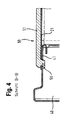
- the locking lug 55 projecting slightly in the lateral direction beyond the edge 51 can engage behind a corresponding edge on the side wall 30 or 40 and / or on the upper cover wall 20 of the refrigeration device 100 in a form-fitting manner, as in FIG Fig. 4 shown.
- Fig. 4 shows a sectional view according to the in Fig. 2 specified cutting profile BB. It can be seen here how the latching lug 55 shown overlaps the apertures in a plate 21 belonging to the upper cover wall 20 and in a sheet metal 41 belonging to the left side wall 40 and engages behind the opening edge in a form-fitting manner, whereby the captive attachment of the transport handle device 50 to the refrigeration device 100 is accomplished becomes.
- the representation in the Fig. 4 is also very good to see that the edge 51 of the transport handle device 50 does not or only slightly beyond the rear wall of the refrigerator. The thermal or flow at the back of the refrigerator is thus not adversely affected.
- the transport handle device 50 can be used analogously in other electrical appliances, such as a dishwasher or a tumble dryer.
Landscapes
- Engineering & Computer Science (AREA)
- Chemical & Material Sciences (AREA)
- Combustion & Propulsion (AREA)
- Physics & Mathematics (AREA)
- Mechanical Engineering (AREA)
- Thermal Sciences (AREA)
- General Engineering & Computer Science (AREA)
- Devices That Are Associated With Refrigeration Equipment (AREA)
- Refrigerator Housings (AREA)
Description
- Die vorliegende Erfindung betrifft ein Haushaltsstandgerät, insbesondere eine Waschmaschine, einen Trockner, oder einen Kühlschrank, oder einen Gefrierschrank, mit wenigs-tens einer an dessen Rückseite angeordneten Transportgriffeinrichtung.
- Aus dem Stand der Technik ist bekannt, an der Rückseite eines Kältegeräts wenigstens eine und in der Regel mehrere Transportgriffeinrichtungen vorzusehen, mittels derer das betreffende Kältegerät angehoben, transportiert und/oder aufgestellt werden kann.
Fig. 1 zeigt die Rückansicht eines Kältegeräts 100', wobei nur der obere Abschnitt dargestellt ist. Das Kältegerät 100' weist eine Rückwand 10', sowie eine rechte Seitenwand 30' und eine linke Seitenwand 40' auf. Im oberen Bereich der Rückwand 10' sind auf selber Höhe zwei identische Transportgriffeinrichtungen 50' angeordnet und an der Rückwand 10' festgeschraubt. Die gezeigten Transportgriffeinrichtungen 50' sind derart ausgebildet, dass eine nach oben wirkende Tragkraft Fv aufgebracht werden kann. Hierzu weisen die Transport-griffeinrichtungen 50' jeweils eine Grifföffnung mit einer dahinterliegenden Griffmulde auf, in welche mehrere Finger einer Hand eingeführt werden können. - Problematisch ist, dass an der Rückwand 10' des Kältegeräts 100' Kühleinrichtungen und dergleichen angeordnet sind, was das Handling beim Transport und/oder Aufstellen erschwert. Ferner sind durch die in der
Fig. 1 gezeigte Anordnung der Transportgriffeinrichtungen 50' die konstruktiven Freiheitsgrade eingeschränkt. - Aus der
JP H02 124480 U JP 11 083286 A - Eine Aufgabe der Erfindung ist es, Möglichkeiten aufzuzeigen, die mit dem Stand der Technik einhergehenden Nachteile zu vermeiden oder zumindest zu vermindern.
- Diese Aufgabe wird gelöst von einem Haushaltsstandgerät mit den Merkmalen des Anspruchs 1. Bevorzugte Weiterbildungen und Ausgestaltungen sind Gegenstand der ahängigen Ansprüche. Bei dem erfindungsgemäßen Kältegerät handelt es sich insbesondere um ein Kältegerät wie einen Kühlschrank oder um einen Gefrierschrank für den Haushalt.
- Zur Lösung der Aufgabe wird ein Haushaltsgerät vorgeschlagen, mit wenigstens einer an der Rückseite angeordneten Transportgriffeinrichtung. Diese Transportgriffeinrichtung weist eine Grifföffnung mit einer dahinterliegenden Griffmulde auf, in welche mehrere Finger einer Hand eingeführt werden können. Es ist vorgesehen, dass die Transportgriffeinrichtung dafür ausgebildet ist, eine Tragkraft aus verschiedenen Richtungen zu ermöglichen. Die diesbezügliche Ausbildung der Transportgriffeinrichtung umfasst zum Beispiel Maßnahmen, um die erforderliche Tragkraft auf die Transportgriffeinrichtung aufbringen zu können und/oder die aufgebrachte Tragkraft in den Gerätekorpus ableiten zu können, so dass das Kältegerät durch Aufbringen einer Tragkraft auch tatsächlich angehoben werden kann.
- Hierdurch kann das Handling insbesondere beim Transport und/oder Aufstellen des Haushaltsstandgeräts deutlich verbessert werden. Ferner wird auch eine verbesserte Unabhängigkeit von den an der Rückseite eines Kältegeräts angeordneten Kühleinrichtungen erzielt.
- Bevorzugt ist die Transportgriffeinrichtung derart ausgebildet, dass bezüglich einer gebrauchsüblichen Aufstellung des Kältegeräts eine Tragkraft nach oben, das heißt in vertikaler Richtung, oder eine Tragkraft zur Seite, das heißt in einer horizontalen Richtung, aufgebracht werden kann.
- Es ist vorgesehen, dass die Transportgriffeinrichtung durch Rastmittel am Gehäuse bzw. am Korpus des Kältegeräts befestigt ist. Ein Rastmittel ist eine Rastnase, die den Rand einer korrespondierenden Öffnung im Gehäuse hintergreifen kann. Hierdurch wird eine schraubenlose Befestigung erzielt.
- Bevorzugt ist die Transportgriffeinrichtung in die Rückwand des Haushaltsstandgeräts integriert, insbesondere zumindest annähernd flächenbündig mit der Rückwand angeordnet.
- Gemäß einer bevorzugten Weiterbildung ist vorgesehen, dass die Transportgriffeinrichtung über die Rückwand des Haushaltsstandgeräts nicht oder nur geringfügig übersteht. Die Thermik bzw. Strömung an der Rückseite des Haushaltsstandgeräts wird somit nicht nachteilig behindert.
- Gemäß einer bevorzugten Weiterbildung ist vorgesehen, dass die Griffmulde der Transportgriffeinrichtung L-förmig ausgebildet ist. Bevorzugt sind die L-Schenkel gleichlang ausgebildet und in einem Winkel von 90° zueinander ausgerichtet. Insbesondere ist vorgesehen, dass die L-Schenkel der L-förmigen Griffmulde symmetrisch zueinander ausgebildet sind.
- Erfindungsgemäß sind die beiden L-Schenkel der L-förmigen Griffmulde mit einer einen Hintergriff ermöglichenden Ausbauchung bzw. Hinterschneidung ausgebildet. Hierdurch wird das Aufbringen einer erforderlichen Tragkraft auf die Transportgriffeinrichtung, insbesondere auch unter ergonomischen Gesichtspunkten, ermöglicht.
- Gemäß einer bevorzugten Weiterbildung ist vorgesehen, dass an der Rückseite der Transportgriffeinrichtung wenigstens ein abragender, insbesondere schräg abragender, stiftartiger Dübel angeordnet ist. Dies wird nachfolgend im Zusammenhang mit den beigefügten Zeichnungen noch näher erläutert. Ein solcher Dübel kann auch eine andere Form aufweisen.
- Gemäß einer bevorzugten Weiterbildung ist vorgesehen, dass in den beiden Stoßbereichen zwischen der Rückwand, der oberen Deckwand und einer Seitenwand des Haushaltsstandgeräts, insbesondere des Kältegeräts jeweils eine Transportgriffeinrichtung angeordnet ist. Somit sind zumindest zwei erfindungsgemäße Transportgriffeinrichtungen am Haushaltsstandgerät umfasst, die bezüglich der in der
Fig. 1 gezeigten Anordnung nach außen und oben verlegt sind, wodurch zum Beispiel das Handling beim Transport und/oder Aufstellen weiter verbessert werden kann. Ferner werden hierdurch konstruktive Freiheitsgrade für die Anordnung von Kühleinrichtungen und dergleichen an der Rückseite des Kältegeräts geschaffen. - Gemäß einer bevorzugten Weiterbildung ist vorgesehen, dass die Transportgriffeinrichtung als separates, einstückiges Bauteil ausgebildet ist. Die Transportgriffeinrichtung ist bevorzugt aus einem Kunststoffmaterial gebildet und insbesondere als Spritzgussteil hergerichtet.
- Weitere Merkmale und Vorteile der Erfindung ergeben sich aus der nachfolgenden Beschreibung eines Ausführungsbeispiels unter Bezugnahme auf die beigefügten Zeichnungen. In diesen zeigen:
- Fig. 1
- die Rückansicht eines Kältegeräts gemäß dem Stand der Technik;
- Fig. 2
- die Rückansicht eines erfindungsgemäßen Kältegeräts;
- Fig. 3
- eine erfindungsgemäße Transportgriffeinrichtung in mehreren Einzelansichten; und
- Fig. 4
- eine Schnittansicht der Rückwand eines erfindungsgemäßen Kältegeräts gemäß dem in
Fig. 2 angegebenen Schnittverlauf. -
Fig. 1 wurde bereits eingangs erläutert.Fig. 2 zeigt in gleicher Rückansicht ein erfindungsgemäßes Kältegerät 100. Das Kältegerät 100 weist eine Rückwand 10, eine obere Deckwand 20, sowie eine rechte Seitenwand 30 und eine linke Seitenwand 40 auf. Die obere Deckwand 20 sowie die beiden Seitenwände 30 und 40 sind beispielhaft als Panelen ausgebildet. In den beiden oberen Stoßbereichen zwischen der Rückwand 10, der oberen Deckwand 20 und den Seitenwänden 30 und 40 ist jeweils eine Transportgriffeinrichtung 50 angeordnet. Die identischen und in verschiedener Winkellage befestigten Transportgriffeinrichtungen 50 sind derart ausgebildet, dass sowohl eine nach oben wirkende Tragkraft FV als auch eine zur jeweiligen Seite wirkende Tragkraft FH aufgebracht werden kann, was ein sehr gutes Handling beim Transport und/oder Aufstellen des Kältegeräts 100 ermöglicht. Hierzu weisen die Transportgriffeinrichtungen 50 jeweils eine L-förmige Grifföffnung mit einer ebenso L-förmigen Griffmulde auf, wie nachfolgend im Zusammenhang mit derFig. 3 näher erläutert. Neben dieser Transportfunktion können die Transportgriffeinrichtungen 50 auch zur mechanischen Stabilisierung des Gerätekorpus dienen. -
Fig. 3a zeigt eine als einstückiges Bauteil ausgebildete Transportgriffeinrichtung 50 in einer perspektivischen Ansicht. Die Transportgriffeinrichtung 50 weist einen kragenförmigen Rand 51 auf, der eine in derselben Ebene liegende L-förmige Eingriffsöffnung umrandet, welche eine ebenfalls L-förmige Griffmulde 52 freigibt. Die Griffmulde 52 ist als geschlossene, in die Tiefe gezogene Fläche ausgebildet. -
Fig. 3b zeigt die Transportgriffeinrichtung 50 in einer Draufsicht, aus der sehr gut die L-förmige Griffmulde 52 zu erkennen ist. Die beiden L-Schenkel sind gleichlang ausgebildet und in einem Winkel von 90° zueinander angeordnet. Bezüglich der gezeigten 45°-Achse A ist die Transportgriffeinrichtung 50 spiegelsymmetrisch ausgebildet, was zum Beispiel die Befestigung in verschiedenen Winkellagen erleichtert. Jeder L-Schenkel ermöglicht das Aufbringen einer Tragkraft F, wie durch die entsprechenden Pfeile angedeutet. Die aufgebrachte Tragkraft F kann über die korrespondierenden und verhältnismäßig groß dimensionierten Längsseiten 53 und 54 in den Gerätekorpus abgeleitet werden. -
Fig. 3c zeigt die Transportgriffeinrichtung 50 in einer Unteransicht. An der Unterseite des Rands 51 sind drei Rastnasen 55 an den gezeigten Stellen angeordnet, die der Befestigung der Transportgriffeinrichtung 50 am Kältegerät 100 dienen. Je nach Positionierung bzw. Winkellage der Transportgriffeinrichtung 50 können die Rastnasen 55 eine korrespondierende Kante an der Seitenwand und an der oberen Deckwand formschlüssig hintergreifen. Auf der Rückseite der Griffmulde 52 sind zwei in unterschiedliche Richtung schräg abragende, stiftartige Dübel 56 angeordnet, welche zum Beispiel in eine Isolierung des Kältegeräts 100 eingreifen können und hierdurch die Befestigung der Transportgriffeinrichtung 50 am Kältegerät 100 unterstützen können. -
Fig. 3d zeigt eine Seitenansicht der Transportgriffeinrichtung 50 gemäß der in derFig. 3a angegebenen Blickrichtung I undFig. 3e zeigt eine Seitenansicht der Transportgriffeinrichtung 50 gemäß der in derFig. 3a angegebenen Blickrichtung II. Gut zu erkennen ist in diesen Darstellungen eine hinter bzw. unterhalb der Eingriffsöffnung ausgebildete Ausbauchung 57 der Griffmulde 52, welche einen Hintergriff ermöglicht, wodurch ergonomisch sinnvoll eine Tragkraft aufgebracht werden kann. Die in der Wandung der Griffmulde ausgebildete Ausbauchung 57 erstreckt sich über die gesamte Schenkellänge des betreffenden L-Schenkels. -
Fig. 3f zeigt eine Detailansicht einer an der Unterseite des Rands 51 angeordneten Rastnase 55, gemäß des in derFig. 3e mit X gekennzeichneten Bereichs. Die in seitlicher Richtung geringfügig über den Rand 51 hervorstehende Rastnase 55 kann eine korrespondierende Kante an der Seitenwand 30 oder 40 und/oder an der oberen Deckwand 20 des Kältegeräts 100 formschlüssig hintergreifen, wie inFig. 4 gezeigt. -
Fig. 4 zeigt eine Schnittansicht gemäß des inFig. 2 angegebenen Schnittverlaufs B-B. Zu erkennen ist hier, wie die gezeigte Rastnase 55 die übereinanderliegenden Öffnungen in einem zur oberen Deckwand 20 gehörenden Blech 21 und in einem zur linken Seitenwand 40 gehörenden Blech 41 durchgreift und den Öffnungsrand formschlüssig hintergreift, wodurch die verliersichere Befestigung der Transportgriffeinrichtung 50 am Kältegerät 100 bewerkstelligt wird. Der Darstellung in derFig. 4 ist ferner sehr gut zu entnehmen, dass der Rand 51 der Transportgriffeinrichtung 50 über die Rückwand des Kältegeräts nicht bzw. nur geringfügig übersteht. Die Thermik bzw. Strömung an der Rückseite des Kältegeräts wird somit nicht nachteilig behindert. - Die Transportgriffeinrichtung 50 kann analog auch bei anderen Elektrogeräten, wie zum Beispiel einer Geschirrspülmaschine oder einem Wäschetrockner, eingesetzt werden.
Claims (8)
- Haushaltsstandgerät (100), insbesondere Kältegerät, mit wenigstens einer an der Rückseite angeordneten Transportgriffeinrichtung (50) mit einer Griffmulde (52), wobei die Transportgriffeinrichtung (50) dafür ausgebildet ist, die Einleitung einer Tragkraft (F) aus verschiedenen Richtungen zu ermöglichen, dadurch gekennzeichnet, dass die Transportgriffeinrichtung (50) durch Rastmittel (55) am Gehäuse des Haushaltsstandgeräts (100) befestigt ist und die Rastmittel (55) Rastnasen sind und dass an einer Unterseite eines Randes (51) der Transportgriffeinrichtung (50) drei Rastnasen angeordnet sind und dass die Rastnasen eine korrespondierende Kante an einer Seitenwand und an einer oberen Deckwand formschlüssig hintergreifen.
- Haushaltsstandgerät (100) nach Anspruch 1,
dadurch gekennzeichnet, dass
die Transportgriffeinrichtung (50) in die Rückwand (10) des Haushaltsstandgeräts (100) integriert ist und insbesondere zumindest weitgehend flächenbündig darin angeordnet ist. - Haushaltsstandgerät (100) nach einem der vorausgehenden Ansprüche,
dadurch gekennzeichnet, dass
die Griffmulde (52) der Transportgriffeinrichtung (50) L-förmig ausgebildet ist. - Haushaltsstandgerät (100) nach Anspruch 3,
dadurch gekennzeichnet, dass
die L-Schenkel der L-förmigen Griffmulde (52) symmetrisch ausgebildet sind. - Haushaltsstandgerät (100) nach Anspruch 3 oder 4,
dadurch gekennzeichnet, dass
beide L-Schenkel der L-förmigen Griffmulde (52) mit einer einen Hintergriff ermöglichenden Ausbauchung (57) ausgebildet sind. - Haushaltsstandgerät (100) nach einem der vorausgehenden Ansprüche,
dadurch gekennzeichnet, dass
rückseitig an der Transportgriffeinrichtung (50) wenigstens ein abragender, stiftartiger Dübel (56) angeordnet ist. - Haushaltsstandgerät (100) nach einem der vorausgehenden Ansprüche,
dadurch gekennzeichnet, dass
in den beiden Stoßbereichen zwischen der Rückwand (10), der oberen Deckwand (20) und einer Seitenwand (30; 40) des Haushaltsstandgeräts (100) jeweils eine Transportgriffeinrichtung (50) angeordnet ist. - Haushaltsstandgerät (100) nach einem der vorausgehenden Ansprüche,
dadurch gekennzeichnet, dass
die Transportgriffeinrichtung (50) als separates, einstückiges Bauteil ausgebildet ist.
Applications Claiming Priority (2)
| Application Number | Priority Date | Filing Date | Title |
|---|---|---|---|
| DE201010003119 DE102010003119A1 (de) | 2010-03-22 | 2010-03-22 | Haushaltsstandgerät mit wenigstens einer Transportgriffeinrichtung |
| PCT/EP2011/052663 WO2011117036A2 (de) | 2010-03-22 | 2011-02-23 | Haushaltsstandgerät mit wenigstens einer transportgriffeinrichtung |
Publications (2)
| Publication Number | Publication Date |
|---|---|
| EP2550494A2 EP2550494A2 (de) | 2013-01-30 |
| EP2550494B1 true EP2550494B1 (de) | 2014-01-22 |
Family
ID=44462007
Family Applications (1)
| Application Number | Title | Priority Date | Filing Date |
|---|---|---|---|
| EP11705533.5A Not-in-force EP2550494B1 (de) | 2010-03-22 | 2011-02-23 | Haushaltsstandgerät mit wenigstens einer transportgriffeinrichtung |
Country Status (3)
| Country | Link |
|---|---|
| EP (1) | EP2550494B1 (de) |
| DE (1) | DE102010003119A1 (de) |
| WO (1) | WO2011117036A2 (de) |
Family Cites Families (5)
| Publication number | Priority date | Publication date | Assignee | Title |
|---|---|---|---|---|
| JPH02124480U (de) * | 1989-03-24 | 1990-10-12 | ||
| JPH10232084A (ja) * | 1997-02-20 | 1998-09-02 | Fujitsu General Ltd | 冷蔵庫 |
| JPH1183286A (ja) * | 1997-09-08 | 1999-03-26 | Hitachi Ltd | 冷蔵庫 |
| JP4090636B2 (ja) * | 1999-08-27 | 2008-05-28 | 松下冷機株式会社 | 冷蔵庫 |
| JP3858937B2 (ja) * | 2004-12-17 | 2006-12-20 | 松下電器産業株式会社 | 冷蔵庫 |
-
2010
- 2010-03-22 DE DE201010003119 patent/DE102010003119A1/de not_active Withdrawn
-
2011
- 2011-02-23 EP EP11705533.5A patent/EP2550494B1/de not_active Not-in-force
- 2011-02-23 WO PCT/EP2011/052663 patent/WO2011117036A2/de not_active Ceased
Also Published As
| Publication number | Publication date |
|---|---|
| DE102010003119A1 (de) | 2011-09-22 |
| WO2011117036A3 (de) | 2011-11-17 |
| EP2550494A2 (de) | 2013-01-30 |
| WO2011117036A2 (de) | 2011-09-29 |
Similar Documents
| Publication | Publication Date | Title |
|---|---|---|
| EP2379794B1 (de) | Haushalts-geschirrspülmaschine | |
| EP2254443A1 (de) | Teleskopierbare auszugsführung | |
| DE112015003102B4 (de) | Starrer Containerboden sowie Container mit demselben | |
| EP2848159B1 (de) | Griff | |
| DE102010037905A1 (de) | Verriegelungsanordnung | |
| EP1615308B3 (de) | Verteiler der Elektroinstallation | |
| DE102016118267A1 (de) | Haltewinkel, Befestigungssystem und Haushaltsgerät | |
| EP3082508A1 (de) | Schubladenwandelement | |
| EP2424761A1 (de) | Schubkarre | |
| WO2010010011A2 (de) | Abdeckung zum abdecken eines lagerwinkels sowie damit ausgerüstetes haushaltsgerät | |
| EP2520210B1 (de) | Haushaltsgerät mit seitlichen, an Kraftaufnehmern gesicherten Gehäusewandungen | |
| WO2011117036A2 (de) | Haushaltsstandgerät mit wenigstens einer transportgriffeinrichtung | |
| EP2305868A1 (de) | Schiebernadel mit eingebautem Mittelsteg | |
| EP2607824A2 (de) | Mechanische Verbindungsvorrichtung für zwei schrankförmige Haushaltsgeräte | |
| EP2790468A2 (de) | Kochfeld und Verfahren zur Montage eines Kochfelds | |
| EP3175763A1 (de) | Geschirrkorb, insbesondere besteckschublade | |
| DE102012102515B4 (de) | Wandelement | |
| DE29710601U1 (de) | Fußgestell für auf Gerätefüßen stehende Haushaltsgeräte | |
| EP2376854A2 (de) | Gehäuse für ein haushaltsgerät | |
| DE102007052081B4 (de) | Haushaltsgerät | |
| DE102008055019A1 (de) | Verpackung mit einem veränderbaren Verpackungsvolumen | |
| DE202015008251U1 (de) | Plattenlager für schwimmend verlegte Steinplatten | |
| EP2280235B1 (de) | Korpus für ein Haushaltsgerät | |
| EP1076143B1 (de) | Haushaltsgerät mit einem Verriegelungselement | |
| EP2607825A2 (de) | Haushaltsgerätekombination |
Legal Events
| Date | Code | Title | Description |
|---|---|---|---|
| PUAI | Public reference made under article 153(3) epc to a published international application that has entered the european phase |
Free format text: ORIGINAL CODE: 0009012 |
|
| 17P | Request for examination filed |
Effective date: 20121022 |
|
| AK | Designated contracting states |
Kind code of ref document: A2 Designated state(s): AL AT BE BG CH CY CZ DE DK EE ES FI FR GB GR HR HU IE IS IT LI LT LU LV MC MK MT NL NO PL PT RO RS SE SI SK SM TR |
|
| RIN1 | Information on inventor provided before grant (corrected) |
Inventor name: KURT, MELIH Inventor name: ERDURAN, ERSIN Inventor name: ARSLAN, FATIH |
|
| DAX | Request for extension of the european patent (deleted) | ||
| GRAP | Despatch of communication of intention to grant a patent |
Free format text: ORIGINAL CODE: EPIDOSNIGR1 |
|
| INTG | Intention to grant announced |
Effective date: 20130911 |
|
| GRAS | Grant fee paid |
Free format text: ORIGINAL CODE: EPIDOSNIGR3 |
|
| GRAA | (expected) grant |
Free format text: ORIGINAL CODE: 0009210 |
|
| AK | Designated contracting states |
Kind code of ref document: B1 Designated state(s): AL AT BE BG CH CY CZ DE DK EE ES FI FR GB GR HR HU IE IS IT LI LT LU LV MC MK MT NL NO PL PT RO RS SE SI SK SM TR |
|
| REG | Reference to a national code |
Ref country code: GB Ref legal event code: FG4D Free format text: NOT ENGLISH |
|
| REG | Reference to a national code |
Ref country code: CH Ref legal event code: EP |
|
| REG | Reference to a national code |
Ref country code: AT Ref legal event code: REF Ref document number: 650991 Country of ref document: AT Kind code of ref document: T Effective date: 20140215 |
|
| REG | Reference to a national code |
Ref country code: IE Ref legal event code: FG4D Free format text: LANGUAGE OF EP DOCUMENT: GERMAN |
|
| REG | Reference to a national code |
Ref country code: DE Ref legal event code: R096 Ref document number: 502011002094 Country of ref document: DE Effective date: 20140306 |
|
| REG | Reference to a national code |
Ref country code: NL Ref legal event code: VDEP Effective date: 20140122 |
|
| REG | Reference to a national code |
Ref country code: LT Ref legal event code: MG4D |
|
| PG25 | Lapsed in a contracting state [announced via postgrant information from national office to epo] |
Ref country code: IS Free format text: LAPSE BECAUSE OF FAILURE TO SUBMIT A TRANSLATION OF THE DESCRIPTION OR TO PAY THE FEE WITHIN THE PRESCRIBED TIME-LIMIT Effective date: 20140522 Ref country code: LT Free format text: LAPSE BECAUSE OF FAILURE TO SUBMIT A TRANSLATION OF THE DESCRIPTION OR TO PAY THE FEE WITHIN THE PRESCRIBED TIME-LIMIT Effective date: 20140122 Ref country code: NO Free format text: LAPSE BECAUSE OF FAILURE TO SUBMIT A TRANSLATION OF THE DESCRIPTION OR TO PAY THE FEE WITHIN THE PRESCRIBED TIME-LIMIT Effective date: 20140422 |
|
| PG25 | Lapsed in a contracting state [announced via postgrant information from national office to epo] |
Ref country code: PT Free format text: LAPSE BECAUSE OF FAILURE TO SUBMIT A TRANSLATION OF THE DESCRIPTION OR TO PAY THE FEE WITHIN THE PRESCRIBED TIME-LIMIT Effective date: 20140522 Ref country code: CY Free format text: LAPSE BECAUSE OF FAILURE TO SUBMIT A TRANSLATION OF THE DESCRIPTION OR TO PAY THE FEE WITHIN THE PRESCRIBED TIME-LIMIT Effective date: 20140122 Ref country code: ES Free format text: LAPSE BECAUSE OF FAILURE TO SUBMIT A TRANSLATION OF THE DESCRIPTION OR TO PAY THE FEE WITHIN THE PRESCRIBED TIME-LIMIT Effective date: 20140122 Ref country code: SE Free format text: LAPSE BECAUSE OF FAILURE TO SUBMIT A TRANSLATION OF THE DESCRIPTION OR TO PAY THE FEE WITHIN THE PRESCRIBED TIME-LIMIT Effective date: 20140122 Ref country code: NL Free format text: LAPSE BECAUSE OF FAILURE TO SUBMIT A TRANSLATION OF THE DESCRIPTION OR TO PAY THE FEE WITHIN THE PRESCRIBED TIME-LIMIT Effective date: 20140122 Ref country code: FI Free format text: LAPSE BECAUSE OF FAILURE TO SUBMIT A TRANSLATION OF THE DESCRIPTION OR TO PAY THE FEE WITHIN THE PRESCRIBED TIME-LIMIT Effective date: 20140122 |
|
| BERE | Be: lapsed |
Owner name: BSH BOSCH UND SIEMENS HAUSGERATE G.M.B.H. Effective date: 20140228 |
|
| PG25 | Lapsed in a contracting state [announced via postgrant information from national office to epo] |
Ref country code: RS Free format text: LAPSE BECAUSE OF FAILURE TO SUBMIT A TRANSLATION OF THE DESCRIPTION OR TO PAY THE FEE WITHIN THE PRESCRIBED TIME-LIMIT Effective date: 20140122 Ref country code: HR Free format text: LAPSE BECAUSE OF FAILURE TO SUBMIT A TRANSLATION OF THE DESCRIPTION OR TO PAY THE FEE WITHIN THE PRESCRIBED TIME-LIMIT Effective date: 20140122 Ref country code: LV Free format text: LAPSE BECAUSE OF FAILURE TO SUBMIT A TRANSLATION OF THE DESCRIPTION OR TO PAY THE FEE WITHIN THE PRESCRIBED TIME-LIMIT Effective date: 20140122 |
|
| REG | Reference to a national code |
Ref country code: CH Ref legal event code: PL |
|
| REG | Reference to a national code |
Ref country code: DE Ref legal event code: R097 Ref document number: 502011002094 Country of ref document: DE |
|
| PG25 | Lapsed in a contracting state [announced via postgrant information from national office to epo] |
Ref country code: RO Free format text: LAPSE BECAUSE OF FAILURE TO SUBMIT A TRANSLATION OF THE DESCRIPTION OR TO PAY THE FEE WITHIN THE PRESCRIBED TIME-LIMIT Effective date: 20140122 Ref country code: LI Free format text: LAPSE BECAUSE OF NON-PAYMENT OF DUE FEES Effective date: 20140228 Ref country code: CZ Free format text: LAPSE BECAUSE OF FAILURE TO SUBMIT A TRANSLATION OF THE DESCRIPTION OR TO PAY THE FEE WITHIN THE PRESCRIBED TIME-LIMIT Effective date: 20140122 Ref country code: EE Free format text: LAPSE BECAUSE OF FAILURE TO SUBMIT A TRANSLATION OF THE DESCRIPTION OR TO PAY THE FEE WITHIN THE PRESCRIBED TIME-LIMIT Effective date: 20140122 Ref country code: CH Free format text: LAPSE BECAUSE OF NON-PAYMENT OF DUE FEES Effective date: 20140228 Ref country code: MC Free format text: LAPSE BECAUSE OF FAILURE TO SUBMIT A TRANSLATION OF THE DESCRIPTION OR TO PAY THE FEE WITHIN THE PRESCRIBED TIME-LIMIT Effective date: 20140122 Ref country code: DK Free format text: LAPSE BECAUSE OF FAILURE TO SUBMIT A TRANSLATION OF THE DESCRIPTION OR TO PAY THE FEE WITHIN THE PRESCRIBED TIME-LIMIT Effective date: 20140122 |
|
| PG25 | Lapsed in a contracting state [announced via postgrant information from national office to epo] |
Ref country code: SK Free format text: LAPSE BECAUSE OF FAILURE TO SUBMIT A TRANSLATION OF THE DESCRIPTION OR TO PAY THE FEE WITHIN THE PRESCRIBED TIME-LIMIT Effective date: 20140122 Ref country code: PL Free format text: LAPSE BECAUSE OF FAILURE TO SUBMIT A TRANSLATION OF THE DESCRIPTION OR TO PAY THE FEE WITHIN THE PRESCRIBED TIME-LIMIT Effective date: 20140122 |
|
| PLBE | No opposition filed within time limit |
Free format text: ORIGINAL CODE: 0009261 |
|
| STAA | Information on the status of an ep patent application or granted ep patent |
Free format text: STATUS: NO OPPOSITION FILED WITHIN TIME LIMIT |
|
| REG | Reference to a national code |
Ref country code: IE Ref legal event code: MM4A |
|
| 26N | No opposition filed |
Effective date: 20141023 |
|
| REG | Reference to a national code |
Ref country code: FR Ref legal event code: ST Effective date: 20141208 |
|
| PG25 | Lapsed in a contracting state [announced via postgrant information from national office to epo] |
Ref country code: FR Free format text: LAPSE BECAUSE OF NON-PAYMENT OF DUE FEES Effective date: 20140324 Ref country code: BE Free format text: LAPSE BECAUSE OF NON-PAYMENT OF DUE FEES Effective date: 20140228 Ref country code: IE Free format text: LAPSE BECAUSE OF NON-PAYMENT OF DUE FEES Effective date: 20140223 |
|
| REG | Reference to a national code |
Ref country code: DE Ref legal event code: R097 Ref document number: 502011002094 Country of ref document: DE Effective date: 20141023 |
|
| REG | Reference to a national code |
Ref country code: DE Ref legal event code: R081 Ref document number: 502011002094 Country of ref document: DE Owner name: BSH HAUSGERAETE GMBH, DE Free format text: FORMER OWNER: BSH BOSCH UND SIEMENS HAUSGERAETE GMBH, 81739 MUENCHEN, DE Effective date: 20150409 |
|
| PG25 | Lapsed in a contracting state [announced via postgrant information from national office to epo] |
Ref country code: SI Free format text: LAPSE BECAUSE OF FAILURE TO SUBMIT A TRANSLATION OF THE DESCRIPTION OR TO PAY THE FEE WITHIN THE PRESCRIBED TIME-LIMIT Effective date: 20140122 |
|
| GBPC | Gb: european patent ceased through non-payment of renewal fee |
Effective date: 20150223 |
|
| PG25 | Lapsed in a contracting state [announced via postgrant information from national office to epo] |
Ref country code: GB Free format text: LAPSE BECAUSE OF NON-PAYMENT OF DUE FEES Effective date: 20150223 |
|
| PG25 | Lapsed in a contracting state [announced via postgrant information from national office to epo] |
Ref country code: MT Free format text: LAPSE BECAUSE OF FAILURE TO SUBMIT A TRANSLATION OF THE DESCRIPTION OR TO PAY THE FEE WITHIN THE PRESCRIBED TIME-LIMIT Effective date: 20140122 |
|
| PG25 | Lapsed in a contracting state [announced via postgrant information from national office to epo] |
Ref country code: SM Free format text: LAPSE BECAUSE OF FAILURE TO SUBMIT A TRANSLATION OF THE DESCRIPTION OR TO PAY THE FEE WITHIN THE PRESCRIBED TIME-LIMIT Effective date: 20140122 |
|
| PG25 | Lapsed in a contracting state [announced via postgrant information from national office to epo] |
Ref country code: GR Free format text: LAPSE BECAUSE OF FAILURE TO SUBMIT A TRANSLATION OF THE DESCRIPTION OR TO PAY THE FEE WITHIN THE PRESCRIBED TIME-LIMIT Effective date: 20140423 Ref country code: IT Free format text: LAPSE BECAUSE OF FAILURE TO SUBMIT A TRANSLATION OF THE DESCRIPTION OR TO PAY THE FEE WITHIN THE PRESCRIBED TIME-LIMIT Effective date: 20140122 Ref country code: BG Free format text: LAPSE BECAUSE OF FAILURE TO SUBMIT A TRANSLATION OF THE DESCRIPTION OR TO PAY THE FEE WITHIN THE PRESCRIBED TIME-LIMIT Effective date: 20140122 |
|
| PG25 | Lapsed in a contracting state [announced via postgrant information from national office to epo] |
Ref country code: HU Free format text: LAPSE BECAUSE OF FAILURE TO SUBMIT A TRANSLATION OF THE DESCRIPTION OR TO PAY THE FEE WITHIN THE PRESCRIBED TIME-LIMIT; INVALID AB INITIO Effective date: 20110223 Ref country code: LU Free format text: LAPSE BECAUSE OF NON-PAYMENT OF DUE FEES Effective date: 20140223 |
|
| REG | Reference to a national code |
Ref country code: AT Ref legal event code: MM01 Ref document number: 650991 Country of ref document: AT Kind code of ref document: T Effective date: 20160223 |
|
| PG25 | Lapsed in a contracting state [announced via postgrant information from national office to epo] |
Ref country code: AT Free format text: LAPSE BECAUSE OF NON-PAYMENT OF DUE FEES Effective date: 20160223 |
|
| PGFP | Annual fee paid to national office [announced via postgrant information from national office to epo] |
Ref country code: DE Payment date: 20180228 Year of fee payment: 8 |
|
| PGFP | Annual fee paid to national office [announced via postgrant information from national office to epo] |
Ref country code: TR Payment date: 20180220 Year of fee payment: 8 |
|
| PG25 | Lapsed in a contracting state [announced via postgrant information from national office to epo] |
Ref country code: MK Free format text: LAPSE BECAUSE OF FAILURE TO SUBMIT A TRANSLATION OF THE DESCRIPTION OR TO PAY THE FEE WITHIN THE PRESCRIBED TIME-LIMIT Effective date: 20140122 |
|
| PG25 | Lapsed in a contracting state [announced via postgrant information from national office to epo] |
Ref country code: AL Free format text: LAPSE BECAUSE OF FAILURE TO SUBMIT A TRANSLATION OF THE DESCRIPTION OR TO PAY THE FEE WITHIN THE PRESCRIBED TIME-LIMIT Effective date: 20140122 |
|
| REG | Reference to a national code |
Ref country code: DE Ref legal event code: R119 Ref document number: 502011002094 Country of ref document: DE |
|
| PG25 | Lapsed in a contracting state [announced via postgrant information from national office to epo] |
Ref country code: DE Free format text: LAPSE BECAUSE OF NON-PAYMENT OF DUE FEES Effective date: 20190903 |
|
| PG25 | Lapsed in a contracting state [announced via postgrant information from national office to epo] |
Ref country code: TR Free format text: LAPSE BECAUSE OF NON-PAYMENT OF DUE FEES Effective date: 20190223 |