EP2550464B1 - Verfahren zur gleichzeitigen herstellung von mehr als einem lagerring für ein kegelrollenlager - Google Patents
Verfahren zur gleichzeitigen herstellung von mehr als einem lagerring für ein kegelrollenlager Download PDFInfo
- Publication number
- EP2550464B1 EP2550464B1 EP11708782.5A EP11708782A EP2550464B1 EP 2550464 B1 EP2550464 B1 EP 2550464B1 EP 11708782 A EP11708782 A EP 11708782A EP 2550464 B1 EP2550464 B1 EP 2550464B1
- Authority
- EP
- European Patent Office
- Prior art keywords
- bearing
- wire material
- bearing rings
- ring
- rings
- Prior art date
- Legal status (The legal status is an assumption and is not a legal conclusion. Google has not performed a legal analysis and makes no representation as to the accuracy of the status listed.)
- Not-in-force
Links
Images
Classifications
-
- F—MECHANICAL ENGINEERING; LIGHTING; HEATING; WEAPONS; BLASTING
- F16—ENGINEERING ELEMENTS AND UNITS; GENERAL MEASURES FOR PRODUCING AND MAINTAINING EFFECTIVE FUNCTIONING OF MACHINES OR INSTALLATIONS; THERMAL INSULATION IN GENERAL
- F16C—SHAFTS; FLEXIBLE SHAFTS; ELEMENTS OR CRANKSHAFT MECHANISMS; ROTARY BODIES OTHER THAN GEARING ELEMENTS; BEARINGS
- F16C33/00—Parts of bearings; Special methods for making bearings or parts thereof
- F16C33/30—Parts of ball or roller bearings
- F16C33/58—Raceways; Race rings
- F16C33/64—Special methods of manufacture
-
- B—PERFORMING OPERATIONS; TRANSPORTING
- B21—MECHANICAL METAL-WORKING WITHOUT ESSENTIALLY REMOVING MATERIAL; PUNCHING METAL
- B21K—MAKING FORGED OR PRESSED METAL PRODUCTS, e.g. HORSE-SHOES, RIVETS, BOLTS OR WHEELS
- B21K1/00—Making machine elements
- B21K1/04—Making machine elements ball-races or sliding bearing races
-
- F—MECHANICAL ENGINEERING; LIGHTING; HEATING; WEAPONS; BLASTING
- F16—ENGINEERING ELEMENTS AND UNITS; GENERAL MEASURES FOR PRODUCING AND MAINTAINING EFFECTIVE FUNCTIONING OF MACHINES OR INSTALLATIONS; THERMAL INSULATION IN GENERAL
- F16C—SHAFTS; FLEXIBLE SHAFTS; ELEMENTS OR CRANKSHAFT MECHANISMS; ROTARY BODIES OTHER THAN GEARING ELEMENTS; BEARINGS
- F16C19/00—Bearings with rolling contact, for exclusively rotary movement
- F16C19/22—Bearings with rolling contact, for exclusively rotary movement with bearing rollers essentially of the same size in one or more circular rows, e.g. needle bearings
- F16C19/34—Bearings with rolling contact, for exclusively rotary movement with bearing rollers essentially of the same size in one or more circular rows, e.g. needle bearings for both radial and axial load
- F16C19/36—Bearings with rolling contact, for exclusively rotary movement with bearing rollers essentially of the same size in one or more circular rows, e.g. needle bearings for both radial and axial load with a single row of rollers
- F16C19/364—Bearings with rolling contact, for exclusively rotary movement with bearing rollers essentially of the same size in one or more circular rows, e.g. needle bearings for both radial and axial load with a single row of rollers with tapered rollers, i.e. rollers having essentially the shape of a truncated cone
-
- F—MECHANICAL ENGINEERING; LIGHTING; HEATING; WEAPONS; BLASTING
- F16—ENGINEERING ELEMENTS AND UNITS; GENERAL MEASURES FOR PRODUCING AND MAINTAINING EFFECTIVE FUNCTIONING OF MACHINES OR INSTALLATIONS; THERMAL INSULATION IN GENERAL
- F16C—SHAFTS; FLEXIBLE SHAFTS; ELEMENTS OR CRANKSHAFT MECHANISMS; ROTARY BODIES OTHER THAN GEARING ELEMENTS; BEARINGS
- F16C2226/00—Joining parts; Fastening; Assembling or mounting parts
- F16C2226/30—Material joints
- F16C2226/36—Material joints by welding
Definitions
- the invention relates to a method for the simultaneous production of more than one bearing ring for a tapered roller bearing.
- Tapered roller bearings are known to have an outer ring, an inner ring and arranged between these two bearing rings conical rolling elements. The rolling elements are held in a cage and roll on obliquely arranged surfaces of the bearing inner ring and the bearing outer ring.
- Such a tapered roller bearing is for example by the DE 10 2008 014 552 A1 known.
- the cage of this tapered roller bearing is made of a wire material.
- the bearing rings are usually manufactured as a forged part, which not only causes a high weight, but also requires a very extensive machinery for processing the same, and requires a relatively time-consuming production process. To prevent these disadvantages, shows the US 3,387,900 a ball bearing with bearing rings made of a flat material.
- the invention has for its object to simplify the production of bearing rings for a tapered roller bearing and to make their production cost.
- the invention is based on the finding that the costs for the production of bearing rings can be significantly reduced if more than one bearing ring of the same kind, ie bearing inner ring or bearing outer ring, are produced simultaneously in as many working steps as possible.
- the bearing rings can be designed as an outer ring or as an inner ring.
- the separation of the profiled, bent, welded and plastered portion of the flat or wire material is carried out in individual bearing rings in individual bearing rings by a radial separating cut or by radial separating rolls.
- a radially thinner, axially aligned connecting portion between the two hitherto still connected individual bearing rings is severed.
- a case hardening steel such as grade 16MnCr5 or a rolling bearing steel.
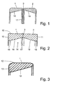
- the Fig. 1 schematically shows a portion of a flat or wire material, which have received according to the inventive method, first by L Lucassprofilieren between two rollers necessary for two outer rings 1, 2 of two tapered roller bearings cross-sectional geometry.
- the longitudinal profiling took place in such a way that the two outer rings 1 and 2 are still connected to each other via a radially thin and axially short web 3.
- the geometry of the two still to be separated outer rings 1 and 2 is almost completely formed.
- a piece in the length was separated from a long portion of the thus profiled flat or wire material, which largely corresponds to the respective circumferential length of the future outer rings of the tapered roller bearings. Then this section was bent annularly, the two free ends welded together, then annealed and then plastered the weld, so straightened and smoothed. Accordingly, shows Fig. 1 the two outer rings 1 and 2 immediately before their separation by a radial separating cut or a separation of the outer rings produced by a separating rollers. Fig. 3 shows one of the two outer rings after the separation process.
- Fig. 1 Alternatively to the embodiment of Fig. 1 is a further embodiment of the invention in connection with Fig. 2 explained.
- Fig. 2 shows a flat or strip material, which was brought by a longitudinal profiling in a predetermined shape, bent around, welded end and plastered.
- the flat or strip material is different from the example of Fig. 1 formed substantially rectangular, with three sides, namely the radially outer surface 12 and the two end faces 11 and 13, straight surfaces.
- straight end faces 11 and 13 are radially inwardly annular surfaces 15 and 16, which are aligned parallel to the radially outer surface 12.
- the radially inner circumferential surface 14 is formed tapering towards a central radial groove 17, wherein the two right and left side regions 18 and 19 approach the radial groove 17 toward the opposite, radially outer surface 12.
- These two regions 18 and 19 are already largely formed as raceways for the conical rolling elements.
- the two still contiguous blanks of the bearing rings 1, 2 are separated from each other in the radial groove 17. Thereafter, a further treatment of the bearing rings 1, 2 by hardening and / or hard machining. After this step, the respective outer ring 1, 2 can then be mounted in the assembly with other parts to a rolling bearing.
- bearing rings 1, 2 it is advantageous if more than one bearing ring 1, 2 is produced simultaneously. It is expedient if the bearing rings are made simultaneously from the flat or wire material. The profiling takes place at the same time, including the closing of the rings, until a separating cut separates the parts, so that they can be further processed and assembled independently of each other.
Landscapes
- Engineering & Computer Science (AREA)
- General Engineering & Computer Science (AREA)
- Mechanical Engineering (AREA)
- Manufacturing & Machinery (AREA)
- Rolling Contact Bearings (AREA)
Description
- Die Erfindung betrifft ein Verfahren zur gleichzeitigen Herstellung von mehr als einem Lagerring für ein Kegelrollenlager.
- Kegelrollenlager weisen bekanntermaßen einen Außenring, einen Innenring und zwischen diesen beiden Lagerringen angeordnete kegelförmige Wälzkörper auf. Die Wälzkörper sind in einem Käfig gehalten und wälzen sich auf schräg zueinander angeordneten Flächen des Lagerinnenrings bzw. des Lageraußenrings ab. Ein solches Kegelrollenlager ist beispielsweise durch die
DE 10 2008 014 552 A1 bekannt geworden. Der Käfig dieses Kegelrollenlagers ist aus einem Drahtmaterial hergestellt. Die Lagerringe werden üblicherweise als Schmiedeteil hergestellt, was nicht nur ein hohes Gewicht bewirkt, sondern auch einen sehr umfangreichen Maschinenpark zur Bearbeitung derselben bedarf, und einen relativ zeitaufwendigen Herstellprozess verlangt. Um diese Nachteile zu verhindern, zeigt dieUS 3 387 900 A ein Kugellager mit aus einem Flachmaterial hergestellten Lagerringen. - Der Erfindung liegt die Aufgabe zugrunde, die Herstellung von Lagerringen für ein Kegelrollenlager zu vereinfachen bzw. deren Herstellung kostengünstig zu gestalten.
- Der Erfindung liegt die Erkenntnis zugrunde, dass sich die Kosten zur Herstellung von Lagerringen deutlich reduzieren lassen, wenn mehr als ein Lagerring der gleichen Sorte, also Lagerinnenring oder Lageraußenring, in möglichst vielen Arbeitsschritten gleichzeitig hergestellt werden.
- Die Erfindung betrifft demnach ein Verfahren zur gleichzeitigen Herstellung von mehr als einem Lagerring für ein Kegelrollenlager, welches gemäß den Merkmalen des Anspruchs 1 durch folgende Verfahrensschritte gekennzeichnet ist:
- Verwenden eines langgestreckten Flach- oder Drahtmaterials als Ausgangsmaterial zur Herstellung der wenigstens zwei Lagerringe,
- Gleichzeitiges Erzeugen der Querschnittsform der wenigstens zwei Lagerringe durch Längsprofilieren des Flach- oder Drahtmaterials,
- Abschneiden eines Abschnitts vom profilierten Flach- oder Drahtmaterial gemäß der jeweiligen Umfangslänge der wenigstens zwei Lagerringe,
- Ringförmiges Biegen des profilierten Abschnitts,
- Verschweißen der Enden des profilierten Abschnitts,
- Glühen zur Reduzierung der Materialhärte
- Verputzen der Schweißnaht
- Trennen der wenigstens zwei Lagerringe.
- Durch dieses Herstellverfahren werden also wenigstens zwei Lagerringe bei fast allen ihren Herstellschritten mit großem Kostenvorteil gleichzeitig bearbeitet. Die Lagerringe können dabei als Außenring oder als Innenring ausgebildet sein.
- Ein nach dem Trennen des profilierten, gebogenen, geschweißten und verputzten Abschnitts des Flach- oder Drahtmaterials in Einzellagerringe können diese, sofern notwenig, noch einer individuellen Endbearbeitung unterzogen werden, welche hinsichtlich der Gesamtzahl der Arbeitsschritte keinen großen Kostenfaktor ausmacht. So kann vorgesehen sein, dass nach dem Verputzen der Schweißnaht oder nach dem Trennen der Lagerringe diese jeweils einsatzgehärtet, gehärtet und/oder hartbearbeitet werden.
- Gemäß einer vorteilhaften Weiterbildung der Erfindung ist vorgesehen, dass das Trennen des profilierten, gebogenen, geschweißten und verputzten Abschnitts des Flach- oder Drahtmaterials in Einzellagerringe in einzelne Lagerringe durch einen radialen Trennschnitt oder durch radiales Trennwalzen erfolgt. Dabei wird ein radial dünner, axial ausgerichteter Verbindungsabschnitt zwischen den beiden bis dahin noch verbundenen einzelnen Lagerringen durchtrennt.
- Hinsichtlich des Flach- oder Drahtmaterial wird vorzugsweise ein Einsatzstahl, beispielsweise der Sorte 16MnCr5, oder ein Wälzlagerstahl verwendet.
- Die Erfindung wird im Folgenden anhand der beiliegenden Zeichnung an bevorzugten Ausführungsformen näher erläutert. Darin zeigt
- Fig. 1
- einen rund gebogenen und an seinen freien Enden zusammengeschweißten Abschnitt eines Flach- oder Drahtmaterials, an dem durch Längsprofilieren die Geometrie von zwei mittig zusammenhängenden Lageraußenring-Rohlingen ausgebildet ist,
- Fig. 2
- eine Darstellung ähnlich der in
Fig. 1 , jedoch mit einer anderen Querschnittsgeometrie, - Fig. 3
- einen hälftigen Axialschnitt durch einen Lageraußenring, der nach dem Verfahren gemäß der Erfindung hergestellt wurde.
- Die
Fig. 1 zeigt schematisch einen Abschnitt von einem Flach- oder Drahtmaterial, welches entsprechend dem erfindungsgemäßen Verfahren zunächst durch Längsprofilieren zwischen zwei Walzen die für zwei Außenringe 1, 2 von zwei Kegelrollenlagern notwenige Querschnittsgeometrie erhalten habt. WieFig. 1 zeigt, erfolgte das Längsprofilieren in der Weise, dass die beiden Außenringe 1 und 2 noch über einen radial dünnen und axial kurzen Steg 3 miteinander verbunden sind. Außerdem ist die Geometrie der beiden noch voneinander zu trennenden Außenringe 1 und 2 fast vollständig ausgebildet. - Anschließend wurde von einem langem Abschnitt des so profilierten Flach- oder Drahtmaterial ein Stück in derjenigen Länge abgetrennt, welches weitgehend der jeweiligen Umfangslänge der zukünftigen Außenringe der Kegelrollenlager entspricht. Sodann wurde dieser Abschnitt ringförmig umgebogen, die beiden freien Enden miteinander verschweißt, dann geglüht und anschließend die Schweißnaht verputzt, also begradigt und geglättet. Demnach zeigt
Fig. 1 die beiden Außenringe 1 und 2 unmittelbar vor deren Trennen durch einen radialen Trennschnitt oder eine durch ein Trennwalzen erzeugte Separierung der Außenringe.Fig. 3 zeigt einen der beiden Außenringe nach dem Trennvorgang. - Alternativ zu dem Ausführungsbeispiel der
Fig. 1 wird ein weiteres Ausführungsbeispiel der Erfindung im Zusammenhang mitFig. 2 erläutert. -
Fig. 2 zeigt ein Flach- oder Bandmaterial, das durch ein Längsprofilieren in eine vorgegebene Form gebracht, rund gebogen, endseitig verschweißt sowie verputzt wurde. Das Flach- oder Bandmaterial ist abweichend vom Beispiel derFig. 1 im Wesentlichen rechteckig ausgebildet, wobei drei Seiten, nämlich die radial äußere Mantelfläche 12 und die beiden Stirnseiten 11 und 13, gerade Flächen aufweisen. An die beiden radial ausgerichteten, geraden Stirnseiten 11 und 13 schließen sich radial innen Ringflächen 15 und 16 an, die parallel zu der radial äußeren Mantelfläche 12 ausgerichtet sind. Zwischen den beiden Ringflächen 15 und 16 ist die radial innere Mantelfläche 14 zu einer mittigen Radialnut 17 hin schräg zulaufend ausgebildet, wobei die beiden rechts- und linksseitigen Bereiche 18 und 19 sich zur Radialnut 17 hin an die gegenüberliegende, radial äußeren Mantelfläche 12 annähern. Diese beiden Bereiche 18 und 19 sind als Laufbahnen für die kegelförmigen Wälzkörper bereits weitgehend ausgebildet. - Anschließend wird das so vorbearbeitete Flach- oder Drahtmaterial gemäß
Fig. 2 durch Ringwalzen ausgewalzt, wodurch eine an den Kanten abgerundete Kontur des Flach- oder Drahtmaterials entsteht, wie es inFig. 1 bereits gezeigt ist. - In einem nachfolgenden Herstellungsschritt werden die beiden noch zusammenhängenden Rohlinge der Lagerringe 1, 2 im Bereich der Radialnut 17 voneinander getrennt. Danach erfolgt eine weitere Behandlung der Lagerringe 1, 2 durch Härten und/oder Hartbearbeiten. Nach diesem Schritt kann der jeweilige Außenring 1, 2 dann in der Montage mit anderen Teilen zu einem Wälzlager montiert werden.
- Erfindungsgemäß ist es vorteilhaft, wenn mehr als ein Lagerring 1, 2 gleichzeitig hergestellt wird. Dabei ist es zweckmäßig, wenn die Lagerringe gleichzeitig aus dem Flach- oder Drahtmaterial hergestellt werden. Die Profilierung erfolgt gleichzeitig, auch das Schließen der Ringe, bis ein Trennschnitt die Teile trennt, so dass sie unabhängig voneinander weiterbearbeitet und montiert werden können.
-
- 1
- Außenring
- 2
- Außenring
- 3
- Steg
- 11
- Stirnseite
- 12
- Radial äußere Mantelfläche
- 13
- Stirnseite
- 14
- Radial innere Mantelfläche
- 15
- Ringfläche
- 16
- Ringfläche
- 17
- Radialnut
- 18
- Bereich, Laufbahn
- 19
- Bereich, Laufbahn
Claims (6)
- Verfahren zur gleichzeitigen Herstellung von mehr als einem Lagerring für ein Kegelrollenlager, gekennzeichnet durch folgende Verfahrensschritte:- Verwenden eines langgestreckten Flach- oder Drahtmaterials als Ausgangsmaterial zur Herstellung der wenigstens zwei Lagerringe (1, 2),- Gleichzeitiges Erzeugen der Querschnittsform der wenigstens zwei Lagerringe (1, 2) durch Längsprofilieren des Flach- oder Drahtmaterials,- Abschneiden eines Abschnitts vom profilierten Flach- oder Drahtmaterial gemäß der jeweiligen Umfangslänge der wenigstens zwei Lagerringe (1, 2),- Ringförmiges Biegen des profilierten Abschnitts,- Verschweißen der Enden des profilierten Abschnitts,- Glühen zur Reduzierung der Materialhärte- Verputzen der Schweißnaht,- Trennen der wenigstens zwei Lagerringe (1, 2).
- Verfahren nach Anspruch 1, dadurch gekennzeichnet, dass das Trennen der Lagerringe (1, 2) durch einen radialen Trennschnitt oder durch radiales Trennwalzen erfolgt.
- Verfahren nach Anspruch 1 oder 2, dadurch gekennzeichnet, dass nach dem Verputzen der Schweißnaht oder nach dem Trennen der Lagerringe (1, 2) diese jeweils einsatzgehärtet, gehärtet und/oder hartbearbeitet werden.
- Verfahren nach einem der vorherigen Ansprüche, dadurch gekennzeichnet, dass als Flach- oder Drahtmaterial ein Einsatzstahl verwendet wird.
- Verfahren Anspruch 4, dadurch gekennzeichnet, dass als Flach- oder Drahtmaterial ein Stahl der Sorte 16MnCr5 oder ein Wälzlagerstahl genutzt wird.
- Verfahren nach einem der vorherigen Ansprüche, dadurch gekennzeichnet, dass der Lagerring (1, 2) als Außenring oder als Innenring ausgebildet ist.
Applications Claiming Priority (2)
| Application Number | Priority Date | Filing Date | Title |
|---|---|---|---|
| DE102010012167A DE102010012167A1 (de) | 2010-03-20 | 2010-03-20 | Verfahren zur gleichzeitigen Herstellung von mehr als einem Lagerring für ein Kegelrollenlager |
| PCT/EP2011/053427 WO2011117063A1 (de) | 2010-03-20 | 2011-03-08 | Verfahren zur gleichzeitigen herstellung von mehr als einem lagerring für ein kegelrollenlager |
Publications (2)
| Publication Number | Publication Date |
|---|---|
| EP2550464A1 EP2550464A1 (de) | 2013-01-30 |
| EP2550464B1 true EP2550464B1 (de) | 2014-03-05 |
Family
ID=44169220
Family Applications (1)
| Application Number | Title | Priority Date | Filing Date |
|---|---|---|---|
| EP11708782.5A Not-in-force EP2550464B1 (de) | 2010-03-20 | 2011-03-08 | Verfahren zur gleichzeitigen herstellung von mehr als einem lagerring für ein kegelrollenlager |
Country Status (4)
| Country | Link |
|---|---|
| EP (1) | EP2550464B1 (de) |
| CN (1) | CN102812263B (de) |
| DE (1) | DE102010012167A1 (de) |
| WO (1) | WO2011117063A1 (de) |
Families Citing this family (1)
| Publication number | Priority date | Publication date | Assignee | Title |
|---|---|---|---|---|
| CN110814262A (zh) * | 2019-10-08 | 2020-02-21 | 江苏保捷锻压有限公司 | 一种双倍高效的齿圈锻压成型工艺 |
Family Cites Families (9)
| Publication number | Priority date | Publication date | Assignee | Title |
|---|---|---|---|---|
| DE657415C (de) * | 1935-01-28 | 1938-03-04 | Timken Roller Bearing Co | Verfahren zur Herstellung von aneinandergereihten zusammenhaengenden Vorwerkstuecken |
| US3387900A (en) * | 1964-10-06 | 1968-06-11 | Skf Ind Inc | Rolling bearing assemblies |
| US3597819A (en) * | 1969-10-27 | 1971-08-10 | Hudson B Scheifele | Method of making a composite tapered roller bearing race |
| JPS62292920A (ja) * | 1986-06-12 | 1987-12-19 | Hiroshi Teramachi | 旋回ベアリング及びその製造法 |
| KR100541720B1 (ko) * | 2002-11-02 | 2006-01-11 | 주식회사 스틸카스피 | 베어링용 내,외측레이스 및 저어널베어링의 제조방법 |
| DE102005014967A1 (de) * | 2005-04-01 | 2006-10-05 | Schaeffler Kg | Geschweißter Wälzlagerring aus Wälzlagerstahl |
| DE102008014552B4 (de) | 2007-03-23 | 2011-02-03 | Ab Skf | Drahtkäfig für Rollenlager |
| DE102008038827A1 (de) * | 2007-08-16 | 2009-03-12 | GM Global Technology Operations, Inc., Detroit | Verfahren zum Herstellen von geteilten Lagerlaufringen |
| CN101576125B (zh) * | 2009-04-03 | 2010-10-13 | 浙江明星轴承有限公司 | 一种圆锥滚子轴承的外圈的制造方法 |
-
2010
- 2010-03-20 DE DE102010012167A patent/DE102010012167A1/de not_active Withdrawn
-
2011
- 2011-03-08 EP EP11708782.5A patent/EP2550464B1/de not_active Not-in-force
- 2011-03-08 WO PCT/EP2011/053427 patent/WO2011117063A1/de not_active Ceased
- 2011-03-08 CN CN201180014963.1A patent/CN102812263B/zh not_active Expired - Fee Related
Also Published As
| Publication number | Publication date |
|---|---|
| WO2011117063A1 (de) | 2011-09-29 |
| DE102010012167A1 (de) | 2011-09-22 |
| EP2550464A1 (de) | 2013-01-30 |
| CN102812263A (zh) | 2012-12-05 |
| CN102812263B (zh) | 2015-10-14 |
Similar Documents
| Publication | Publication Date | Title |
|---|---|---|
| EP2917597B1 (de) | Laufring für ein hülsenlager | |
| DE102014226644B4 (de) | Verfahren zum gleichzeitigen, segmentweisen Schweißen eines Differentialgehäuses mit einem Ring-Zahnrad | |
| DE102016222336A1 (de) | Wälzlagerkäfig und Verfahren zu dessen Herstellung | |
| DE102014218405B3 (de) | Verfahren zur Herstellung einer Spindel für einen Kugelgewindetrieb, sowie eine danach hergestellte Spindel | |
| EP2478236B1 (de) | Kugelrollenlager | |
| EP3337989B1 (de) | Verfahren zur fertigung einer kegelrollenbaugruppe sowie kegelrollenbaugruppe und kegelrollenlager | |
| WO2008074560A2 (de) | Verfahren zur herstellung eines synchronringes einer synchronisiereinrichtung | |
| DE102011087444A1 (de) | Verfahren zum Herstellen eines Lagerbauteiles, Lagerbauteil sowie Pendelrollenlager | |
| EP2550464A1 (de) | Verfahren zur gleichzeitigen herstellung von mehr als einem lagerring für ein kegelrollenlager | |
| EP3023171B1 (de) | Drückwalzen von lagerringen | |
| DE10320323B4 (de) | Verfahren zur Herstellung des Käfigs | |
| DE102013008658A1 (de) | Antriebselement mit einem Kegelrad für einen Kraftwagen sowie Verfahren zum Herstellen eines solchen Antriebselements | |
| DE102007012831B4 (de) | Verfahren zur Herstellung von Wälzkörperkäfigen | |
| EP2312175B1 (de) | Ring für ein Wälzlager und Verfahren zu seiner Herstellung | |
| EP3494317B1 (de) | Seitenring eines mehrteiligen wälzlagerkäfigs, verfahren zum fertigen des seitenrings sowie mehrteiliger wälzlagerkäfig | |
| DE102016107240A1 (de) | Verfahren zur Herstellung einer Schiebemuffe für eine Schaltgetriebe-Synchronbaugruppe sowie mittels des Verfahrens hergestellte Schiebemuffe | |
| DE102016115798B3 (de) | Verfahren und Einrichtung zur Herstellung von Kolbenringen | |
| WO2014183755A1 (de) | Zweireihiges schrägkugellager und verfahren zu seiner herstellung | |
| DE102009056142A1 (de) | Spanlos hergestellte Lagerschale | |
| DE102014223985A1 (de) | Rotorwelle eines Abgasturboladers | |
| DE102011006815A1 (de) | Lagerring und Wälzlager sowie Verfahren zur Herstellung eines Lagerrings | |
| DE102005043071B3 (de) | Verfahren zur Herstellung eines Lagerringes | |
| DE102014206978A1 (de) | Verfahren zur Herstellung einer Lagerkomponente und Lagerkomponente | |
| DE102016222714A1 (de) | Außenring für ein Zylinderrollenlager sowie Verfahren zu dessen Herstellung | |
| DE102016206115A1 (de) | Verbindungssteg sowie Verfahren zu dessen Herstellung |
Legal Events
| Date | Code | Title | Description |
|---|---|---|---|
| PUAI | Public reference made under article 153(3) epc to a published international application that has entered the european phase |
Free format text: ORIGINAL CODE: 0009012 |
|
| 17P | Request for examination filed |
Effective date: 20121022 |
|
| AK | Designated contracting states |
Kind code of ref document: A1 Designated state(s): AL AT BE BG CH CY CZ DE DK EE ES FI FR GB GR HR HU IE IS IT LI LT LU LV MC MK MT NL NO PL PT RO RS SE SI SK SM TR |
|
| DAX | Request for extension of the european patent (deleted) | ||
| GRAP | Despatch of communication of intention to grant a patent |
Free format text: ORIGINAL CODE: EPIDOSNIGR1 |
|
| INTG | Intention to grant announced |
Effective date: 20131009 |
|
| GRAS | Grant fee paid |
Free format text: ORIGINAL CODE: EPIDOSNIGR3 |
|
| GRAA | (expected) grant |
Free format text: ORIGINAL CODE: 0009210 |
|
| AK | Designated contracting states |
Kind code of ref document: B1 Designated state(s): AL AT BE BG CH CY CZ DE DK EE ES FI FR GB GR HR HU IE IS IT LI LT LU LV MC MK MT NL NO PL PT RO RS SE SI SK SM TR |
|
| REG | Reference to a national code |
Ref country code: GB Ref legal event code: FG4D Free format text: NOT ENGLISH |
|
| REG | Reference to a national code |
Ref country code: CH Ref legal event code: EP |
|
| REG | Reference to a national code |
Ref country code: AT Ref legal event code: REF Ref document number: 655084 Country of ref document: AT Kind code of ref document: T Effective date: 20140315 |
|
| RAP2 | Party data changed (patent owner data changed or rights of a patent transferred) |
Owner name: SCHAEFFLER TECHNOLOGIES GMBH & CO. KG |
|
| REG | Reference to a national code |
Ref country code: IE Ref legal event code: FG4D Free format text: LANGUAGE OF EP DOCUMENT: GERMAN |
|
| REG | Reference to a national code |
Ref country code: DE Ref legal event code: R096 Ref document number: 502011002303 Country of ref document: DE Effective date: 20140417 |
|
| REG | Reference to a national code |
Ref country code: SE Ref legal event code: TRGR |
|
| REG | Reference to a national code |
Ref country code: AT Ref legal event code: HC Ref document number: 655084 Country of ref document: AT Kind code of ref document: T Owner name: SCHAEFFLER TECHNOLOGIES GMBH & CO. KG, DE Effective date: 20140506 |
|
| REG | Reference to a national code |
Ref country code: NL Ref legal event code: VDEP Effective date: 20140305 |
|
| PG25 | Lapsed in a contracting state [announced via postgrant information from national office to epo] |
Ref country code: NO Free format text: LAPSE BECAUSE OF FAILURE TO SUBMIT A TRANSLATION OF THE DESCRIPTION OR TO PAY THE FEE WITHIN THE PRESCRIBED TIME-LIMIT Effective date: 20140605 Ref country code: LT Free format text: LAPSE BECAUSE OF FAILURE TO SUBMIT A TRANSLATION OF THE DESCRIPTION OR TO PAY THE FEE WITHIN THE PRESCRIBED TIME-LIMIT Effective date: 20140305 |
|
| REG | Reference to a national code |
Ref country code: LT Ref legal event code: MG4D |
|
| PG25 | Lapsed in a contracting state [announced via postgrant information from national office to epo] |
Ref country code: FI Free format text: LAPSE BECAUSE OF FAILURE TO SUBMIT A TRANSLATION OF THE DESCRIPTION OR TO PAY THE FEE WITHIN THE PRESCRIBED TIME-LIMIT Effective date: 20140305 Ref country code: CY Free format text: LAPSE BECAUSE OF FAILURE TO SUBMIT A TRANSLATION OF THE DESCRIPTION OR TO PAY THE FEE WITHIN THE PRESCRIBED TIME-LIMIT Effective date: 20140305 |
|
| PG25 | Lapsed in a contracting state [announced via postgrant information from national office to epo] |
Ref country code: HR Free format text: LAPSE BECAUSE OF FAILURE TO SUBMIT A TRANSLATION OF THE DESCRIPTION OR TO PAY THE FEE WITHIN THE PRESCRIBED TIME-LIMIT Effective date: 20140305 Ref country code: RS Free format text: LAPSE BECAUSE OF FAILURE TO SUBMIT A TRANSLATION OF THE DESCRIPTION OR TO PAY THE FEE WITHIN THE PRESCRIBED TIME-LIMIT Effective date: 20140305 Ref country code: LV Free format text: LAPSE BECAUSE OF FAILURE TO SUBMIT A TRANSLATION OF THE DESCRIPTION OR TO PAY THE FEE WITHIN THE PRESCRIBED TIME-LIMIT Effective date: 20140305 |
|
| PG25 | Lapsed in a contracting state [announced via postgrant information from national office to epo] |
Ref country code: IS Free format text: LAPSE BECAUSE OF FAILURE TO SUBMIT A TRANSLATION OF THE DESCRIPTION OR TO PAY THE FEE WITHIN THE PRESCRIBED TIME-LIMIT Effective date: 20140705 Ref country code: RO Free format text: LAPSE BECAUSE OF FAILURE TO SUBMIT A TRANSLATION OF THE DESCRIPTION OR TO PAY THE FEE WITHIN THE PRESCRIBED TIME-LIMIT Effective date: 20140305 Ref country code: CZ Free format text: LAPSE BECAUSE OF FAILURE TO SUBMIT A TRANSLATION OF THE DESCRIPTION OR TO PAY THE FEE WITHIN THE PRESCRIBED TIME-LIMIT Effective date: 20140305 Ref country code: BG Free format text: LAPSE BECAUSE OF FAILURE TO SUBMIT A TRANSLATION OF THE DESCRIPTION OR TO PAY THE FEE WITHIN THE PRESCRIBED TIME-LIMIT Effective date: 20140605 Ref country code: NL Free format text: LAPSE BECAUSE OF FAILURE TO SUBMIT A TRANSLATION OF THE DESCRIPTION OR TO PAY THE FEE WITHIN THE PRESCRIBED TIME-LIMIT Effective date: 20140305 Ref country code: EE Free format text: LAPSE BECAUSE OF FAILURE TO SUBMIT A TRANSLATION OF THE DESCRIPTION OR TO PAY THE FEE WITHIN THE PRESCRIBED TIME-LIMIT Effective date: 20140305 |
|
| REG | Reference to a national code |
Ref country code: CH Ref legal event code: PL |
|
| PG25 | Lapsed in a contracting state [announced via postgrant information from national office to epo] |
Ref country code: SK Free format text: LAPSE BECAUSE OF FAILURE TO SUBMIT A TRANSLATION OF THE DESCRIPTION OR TO PAY THE FEE WITHIN THE PRESCRIBED TIME-LIMIT Effective date: 20140305 Ref country code: PL Free format text: LAPSE BECAUSE OF FAILURE TO SUBMIT A TRANSLATION OF THE DESCRIPTION OR TO PAY THE FEE WITHIN THE PRESCRIBED TIME-LIMIT Effective date: 20140305 Ref country code: ES Free format text: LAPSE BECAUSE OF FAILURE TO SUBMIT A TRANSLATION OF THE DESCRIPTION OR TO PAY THE FEE WITHIN THE PRESCRIBED TIME-LIMIT Effective date: 20140305 |
|
| REG | Reference to a national code |
Ref country code: DE Ref legal event code: R097 Ref document number: 502011002303 Country of ref document: DE |
|
| PG25 | Lapsed in a contracting state [announced via postgrant information from national office to epo] |
Ref country code: PT Free format text: LAPSE BECAUSE OF FAILURE TO SUBMIT A TRANSLATION OF THE DESCRIPTION OR TO PAY THE FEE WITHIN THE PRESCRIBED TIME-LIMIT Effective date: 20140707 |
|
| REG | Reference to a national code |
Ref country code: IE Ref legal event code: MM4A |
|
| PLBE | No opposition filed within time limit |
Free format text: ORIGINAL CODE: 0009261 |
|
| STAA | Information on the status of an ep patent application or granted ep patent |
Free format text: STATUS: NO OPPOSITION FILED WITHIN TIME LIMIT |
|
| PG25 | Lapsed in a contracting state [announced via postgrant information from national office to epo] |
Ref country code: CH Free format text: LAPSE BECAUSE OF NON-PAYMENT OF DUE FEES Effective date: 20140331 Ref country code: MC Free format text: LAPSE BECAUSE OF FAILURE TO SUBMIT A TRANSLATION OF THE DESCRIPTION OR TO PAY THE FEE WITHIN THE PRESCRIBED TIME-LIMIT Effective date: 20140305 Ref country code: LI Free format text: LAPSE BECAUSE OF NON-PAYMENT OF DUE FEES Effective date: 20140331 Ref country code: DK Free format text: LAPSE BECAUSE OF FAILURE TO SUBMIT A TRANSLATION OF THE DESCRIPTION OR TO PAY THE FEE WITHIN THE PRESCRIBED TIME-LIMIT Effective date: 20140305 Ref country code: IE Free format text: LAPSE BECAUSE OF NON-PAYMENT OF DUE FEES Effective date: 20140308 |
|
| 26N | No opposition filed |
Effective date: 20141208 |
|
| REG | Reference to a national code |
Ref country code: DE Ref legal event code: R097 Ref document number: 502011002303 Country of ref document: DE Effective date: 20141208 |
|
| PG25 | Lapsed in a contracting state [announced via postgrant information from national office to epo] |
Ref country code: IT Free format text: LAPSE BECAUSE OF FAILURE TO SUBMIT A TRANSLATION OF THE DESCRIPTION OR TO PAY THE FEE WITHIN THE PRESCRIBED TIME-LIMIT Effective date: 20140305 |
|
| REG | Reference to a national code |
Ref country code: DE Ref legal event code: R081 Ref document number: 502011002303 Country of ref document: DE Owner name: SCHAEFFLER TECHNOLOGIES AG & CO. KG, DE Free format text: FORMER OWNER: SCHAEFFLER TECHNOLOGIES GMBH & CO. KG, 91074 HERZOGENAURACH, DE Effective date: 20150408 Ref country code: DE Ref legal event code: R081 Ref document number: 502011002303 Country of ref document: DE Owner name: SCHAEFFLER TECHNOLOGIES AG & CO. KG, DE Free format text: FORMER OWNER: SCHAEFFLER TECHNOLOGIES AG & CO. KG, 91074 HERZOGENAURACH, DE Effective date: 20140319 |
|
| PG25 | Lapsed in a contracting state [announced via postgrant information from national office to epo] |
Ref country code: SI Free format text: LAPSE BECAUSE OF FAILURE TO SUBMIT A TRANSLATION OF THE DESCRIPTION OR TO PAY THE FEE WITHIN THE PRESCRIBED TIME-LIMIT Effective date: 20140305 |
|
| GBPC | Gb: european patent ceased through non-payment of renewal fee |
Effective date: 20150308 |
|
| PG25 | Lapsed in a contracting state [announced via postgrant information from national office to epo] |
Ref country code: GB Free format text: LAPSE BECAUSE OF NON-PAYMENT OF DUE FEES Effective date: 20150308 |
|
| PG25 | Lapsed in a contracting state [announced via postgrant information from national office to epo] |
Ref country code: MT Free format text: LAPSE BECAUSE OF FAILURE TO SUBMIT A TRANSLATION OF THE DESCRIPTION OR TO PAY THE FEE WITHIN THE PRESCRIBED TIME-LIMIT Effective date: 20140305 |
|
| REG | Reference to a national code |
Ref country code: FR Ref legal event code: PLFP Year of fee payment: 6 |
|
| PG25 | Lapsed in a contracting state [announced via postgrant information from national office to epo] |
Ref country code: SM Free format text: LAPSE BECAUSE OF FAILURE TO SUBMIT A TRANSLATION OF THE DESCRIPTION OR TO PAY THE FEE WITHIN THE PRESCRIBED TIME-LIMIT Effective date: 20140305 |
|
| PG25 | Lapsed in a contracting state [announced via postgrant information from national office to epo] |
Ref country code: GR Free format text: LAPSE BECAUSE OF FAILURE TO SUBMIT A TRANSLATION OF THE DESCRIPTION OR TO PAY THE FEE WITHIN THE PRESCRIBED TIME-LIMIT Effective date: 20140606 |
|
| PG25 | Lapsed in a contracting state [announced via postgrant information from national office to epo] |
Ref country code: TR Free format text: LAPSE BECAUSE OF FAILURE TO SUBMIT A TRANSLATION OF THE DESCRIPTION OR TO PAY THE FEE WITHIN THE PRESCRIBED TIME-LIMIT Effective date: 20140305 Ref country code: HU Free format text: LAPSE BECAUSE OF FAILURE TO SUBMIT A TRANSLATION OF THE DESCRIPTION OR TO PAY THE FEE WITHIN THE PRESCRIBED TIME-LIMIT; INVALID AB INITIO Effective date: 20110308 Ref country code: LU Free format text: LAPSE BECAUSE OF NON-PAYMENT OF DUE FEES Effective date: 20140308 Ref country code: BE Free format text: LAPSE BECAUSE OF FAILURE TO SUBMIT A TRANSLATION OF THE DESCRIPTION OR TO PAY THE FEE WITHIN THE PRESCRIBED TIME-LIMIT Effective date: 20140331 |
|
| REG | Reference to a national code |
Ref country code: FR Ref legal event code: PLFP Year of fee payment: 7 |
|
| PGFP | Annual fee paid to national office [announced via postgrant information from national office to epo] |
Ref country code: FR Payment date: 20170327 Year of fee payment: 7 Ref country code: SE Payment date: 20170324 Year of fee payment: 7 |
|
| REG | Reference to a national code |
Ref country code: AT Ref legal event code: MM01 Ref document number: 655084 Country of ref document: AT Kind code of ref document: T Effective date: 20160308 |
|
| PG25 | Lapsed in a contracting state [announced via postgrant information from national office to epo] |
Ref country code: AT Free format text: LAPSE BECAUSE OF NON-PAYMENT OF DUE FEES Effective date: 20160308 |
|
| PG25 | Lapsed in a contracting state [announced via postgrant information from national office to epo] |
Ref country code: MK Free format text: LAPSE BECAUSE OF FAILURE TO SUBMIT A TRANSLATION OF THE DESCRIPTION OR TO PAY THE FEE WITHIN THE PRESCRIBED TIME-LIMIT Effective date: 20140305 |
|
| PG25 | Lapsed in a contracting state [announced via postgrant information from national office to epo] |
Ref country code: AL Free format text: LAPSE BECAUSE OF FAILURE TO SUBMIT A TRANSLATION OF THE DESCRIPTION OR TO PAY THE FEE WITHIN THE PRESCRIBED TIME-LIMIT Effective date: 20140305 Ref country code: SE Free format text: LAPSE BECAUSE OF NON-PAYMENT OF DUE FEES Effective date: 20180309 |
|
| PG25 | Lapsed in a contracting state [announced via postgrant information from national office to epo] |
Ref country code: FR Free format text: LAPSE BECAUSE OF NON-PAYMENT OF DUE FEES Effective date: 20180331 |
|
| PGFP | Annual fee paid to national office [announced via postgrant information from national office to epo] |
Ref country code: DE Payment date: 20210520 Year of fee payment: 11 |
|
| REG | Reference to a national code |
Ref country code: DE Ref legal event code: R119 Ref document number: 502011002303 Country of ref document: DE |
|
| PG25 | Lapsed in a contracting state [announced via postgrant information from national office to epo] |
Ref country code: DE Free format text: LAPSE BECAUSE OF NON-PAYMENT OF DUE FEES Effective date: 20221001 |
|
| P01 | Opt-out of the competence of the unified patent court (upc) registered |
Effective date: 20230522 |