EP2549911B1 - Procede de fabrication d' une structure allongee souple a extremite orientable - Google Patents
Procede de fabrication d' une structure allongee souple a extremite orientable Download PDFInfo
- Publication number
- EP2549911B1 EP2549911B1 EP11710712.8A EP11710712A EP2549911B1 EP 2549911 B1 EP2549911 B1 EP 2549911B1 EP 11710712 A EP11710712 A EP 11710712A EP 2549911 B1 EP2549911 B1 EP 2549911B1
- Authority
- EP
- European Patent Office
- Prior art keywords
- tubes
- famf
- smaw
- elongate structure
- crimped
- Prior art date
- Legal status (The legal status is an assumption and is not a legal conclusion. Google has not performed a legal analysis and makes no representation as to the accuracy of the status listed.)
- Active
Links
Images

Classifications
-
- A—HUMAN NECESSITIES
- A61—MEDICAL OR VETERINARY SCIENCE; HYGIENE
- A61M—DEVICES FOR INTRODUCING MEDIA INTO, OR ONTO, THE BODY; DEVICES FOR TRANSDUCING BODY MEDIA OR FOR TAKING MEDIA FROM THE BODY; DEVICES FOR PRODUCING OR ENDING SLEEP OR STUPOR
- A61M25/00—Catheters; Hollow probes
- A61M25/01—Introducing, guiding, advancing, emplacing or holding catheters
- A61M25/0105—Steering means as part of the catheter or advancing means; Markers for positioning
- A61M25/0133—Tip steering devices
-
- A—HUMAN NECESSITIES
- A61—MEDICAL OR VETERINARY SCIENCE; HYGIENE
- A61B—DIAGNOSIS; SURGERY; IDENTIFICATION
- A61B1/00—Instruments for performing medical examinations of the interior of cavities or tubes of the body by visual or photographical inspection, e.g. endoscopes; Illuminating arrangements therefor
- A61B1/00064—Constructional details of the endoscope body
- A61B1/00071—Insertion part of the endoscope body
- A61B1/00078—Insertion part of the endoscope body with stiffening means
-
- A—HUMAN NECESSITIES
- A61—MEDICAL OR VETERINARY SCIENCE; HYGIENE
- A61B—DIAGNOSIS; SURGERY; IDENTIFICATION
- A61B1/00—Instruments for performing medical examinations of the interior of cavities or tubes of the body by visual or photographical inspection, e.g. endoscopes; Illuminating arrangements therefor
- A61B1/00064—Constructional details of the endoscope body
- A61B1/0011—Manufacturing of endoscope parts
-
- A—HUMAN NECESSITIES
- A61—MEDICAL OR VETERINARY SCIENCE; HYGIENE
- A61B—DIAGNOSIS; SURGERY; IDENTIFICATION
- A61B1/00—Instruments for performing medical examinations of the interior of cavities or tubes of the body by visual or photographical inspection, e.g. endoscopes; Illuminating arrangements therefor
- A61B1/005—Flexible endoscopes
- A61B1/0051—Flexible endoscopes with controlled bending of insertion part
- A61B1/0052—Constructional details of control elements, e.g. handles
- A61B1/0053—Constructional details of control elements, e.g. handles using distributed actuators, e.g. artificial muscles
-
- A—HUMAN NECESSITIES
- A61—MEDICAL OR VETERINARY SCIENCE; HYGIENE
- A61B—DIAGNOSIS; SURGERY; IDENTIFICATION
- A61B1/00—Instruments for performing medical examinations of the interior of cavities or tubes of the body by visual or photographical inspection, e.g. endoscopes; Illuminating arrangements therefor
- A61B1/005—Flexible endoscopes
- A61B1/0051—Flexible endoscopes with controlled bending of insertion part
- A61B1/0055—Constructional details of insertion parts, e.g. vertebral elements
-
- A—HUMAN NECESSITIES
- A61—MEDICAL OR VETERINARY SCIENCE; HYGIENE
- A61B—DIAGNOSIS; SURGERY; IDENTIFICATION
- A61B1/00—Instruments for performing medical examinations of the interior of cavities or tubes of the body by visual or photographical inspection, e.g. endoscopes; Illuminating arrangements therefor
- A61B1/005—Flexible endoscopes
- A61B1/0051—Flexible endoscopes with controlled bending of insertion part
- A61B1/0055—Constructional details of insertion parts, e.g. vertebral elements
- A61B1/0056—Constructional details of insertion parts, e.g. vertebral elements the insertion parts being asymmetric, e.g. for unilateral bending mechanisms
-
- A—HUMAN NECESSITIES
- A61—MEDICAL OR VETERINARY SCIENCE; HYGIENE
- A61B—DIAGNOSIS; SURGERY; IDENTIFICATION
- A61B1/00—Instruments for performing medical examinations of the interior of cavities or tubes of the body by visual or photographical inspection, e.g. endoscopes; Illuminating arrangements therefor
- A61B1/005—Flexible endoscopes
- A61B1/0051—Flexible endoscopes with controlled bending of insertion part
- A61B1/0057—Constructional details of force transmission elements, e.g. control wires
-
- A—HUMAN NECESSITIES
- A61—MEDICAL OR VETERINARY SCIENCE; HYGIENE
- A61M—DEVICES FOR INTRODUCING MEDIA INTO, OR ONTO, THE BODY; DEVICES FOR TRANSDUCING BODY MEDIA OR FOR TAKING MEDIA FROM THE BODY; DEVICES FOR PRODUCING OR ENDING SLEEP OR STUPOR
- A61M25/00—Catheters; Hollow probes
- A61M25/01—Introducing, guiding, advancing, emplacing or holding catheters
- A61M25/0105—Steering means as part of the catheter or advancing means; Markers for positioning
-
- A—HUMAN NECESSITIES
- A61—MEDICAL OR VETERINARY SCIENCE; HYGIENE
- A61M—DEVICES FOR INTRODUCING MEDIA INTO, OR ONTO, THE BODY; DEVICES FOR TRANSDUCING BODY MEDIA OR FOR TAKING MEDIA FROM THE BODY; DEVICES FOR PRODUCING OR ENDING SLEEP OR STUPOR
- A61M25/00—Catheters; Hollow probes
- A61M25/01—Introducing, guiding, advancing, emplacing or holding catheters
- A61M25/02—Holding devices, e.g. on the body
- A61M2025/0213—Holding devices, e.g. on the body where the catheter is attached by means specifically adapted to a part of the human body
-
- A—HUMAN NECESSITIES
- A61—MEDICAL OR VETERINARY SCIENCE; HYGIENE
- A61M—DEVICES FOR INTRODUCING MEDIA INTO, OR ONTO, THE BODY; DEVICES FOR TRANSDUCING BODY MEDIA OR FOR TAKING MEDIA FROM THE BODY; DEVICES FOR PRODUCING OR ENDING SLEEP OR STUPOR
- A61M25/00—Catheters; Hollow probes
- A61M25/01—Introducing, guiding, advancing, emplacing or holding catheters
- A61M25/02—Holding devices, e.g. on the body
- A61M2025/028—Holding devices, e.g. on the body having a mainly rigid support structure
-
- Y—GENERAL TAGGING OF NEW TECHNOLOGICAL DEVELOPMENTS; GENERAL TAGGING OF CROSS-SECTIONAL TECHNOLOGIES SPANNING OVER SEVERAL SECTIONS OF THE IPC; TECHNICAL SUBJECTS COVERED BY FORMER USPC CROSS-REFERENCE ART COLLECTIONS [XRACs] AND DIGESTS
- Y10—TECHNICAL SUBJECTS COVERED BY FORMER USPC
- Y10T—TECHNICAL SUBJECTS COVERED BY FORMER US CLASSIFICATION
- Y10T29/00—Metal working
- Y10T29/49—Method of mechanical manufacture
- Y10T29/49826—Assembling or joining
- Y10T29/49908—Joining by deforming
Definitions
- the present invention relates to a method of manufacturing a flexible elongate structure with steerable end.
- the invention will advantageously have application in the medical field and more particularly for the production of an endoscope or a catheter.
- the invention may also be used in other various technical fields using elongated structures with steerable ends such as non-destructive control of pipes.
- catheters or endoscopes which have at their ends an elongated orientable body to facilitate the insertion and progression of the elongated body within the human body.
- the structure of the elongated body comprises at least one actuating member for bending the end to be able to negotiate turns and move in non-rectilinear parts of the human body or to visualize or treat parts of the body that are not not arranged in the main axis of the elongated body.
- FAMFs shape memory alloy wires
- the FAMFs extend along the elongate body, their ends being anchored thereon.
- the FAMFs are associated with means of their heating, for example by Joule effect, causing their contraction, in order to cause bending of the elongated body.
- power supply wires are connected to the FAMFs.
- the FAMF must firstly be fixed at its ends on the longitudinal body, and secondly be connected to the supply wire.
- the extra thickness due to the FAMFs and the connecting means of the FAMFs to the body must be minimal so that the assembly has a small footprint necessary for the passage of the structure in small diameter pipes.
- the present invention aims to propose an improvement of these orientable longitudinal structures comprising FAMF actuators.
- the invention relates to a method for manufacturing an elongate structure with a steerable end comprising a flexible longitudinal body associated with at least one actuating member comprising at least one shape memory alloy wire or FAMF extending long body being anchored on it at its ends and associated with means of its controlled heating.
- crimped tubes facilitates the manipulation of the FAMF during its positioning along the body, without risk of deterioration of the FAMF during installation.
- the crimps deform the outer surface of the tubes, which allows, especially if the tubes are ligated to the body, a better holding of the connection between the tubes and the body, in view of tensile stresses caused by the contraction of the FAMF.
- the tube can be selected electrically conductive and thus be connected to the power supply wire, thereby facilitating the electrical connection between the power supply wire and the FAMF.
- This characteristic makes it possible to obtain an increased curvature of the portion of the longitudinal body that extends between the end tubes and consequently facilitates the orientation and the displacement of the longitudinal structure by the practitioner.
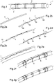
- the figure 1 illustrates a longitudinal structure with steerable end 1 comprising a flexible longitudinal body 2 associated with an actuating member 3 which comprises a FAMF 4 extending along the body 2.
- the FAMF extends within a number of tubes 5a, 5b, 5c, 5d which are secured to the body 2 by ligaments 7.
- all the tubes are crimped on the FAMF 4.
- the tubes here are electrically conductive, and the end tubes 5a and 5d are connected to power supply son to heat the FAMF 4 by Joule effect, which causes its contraction and thus the flexion of the body part 2 along which the FAMF 4 extends.
- a first method of manufacture the steps of which are illustrated in Figures 2a to 2g , starting from a sheath 5 of rigid conductive material that is cut as illustrated in FIG. figure 2b to allow tubular sections 5a to 5d to remain connected together by ligaments 7. Then, as can be seen in FIG. Figure 2c , the FAMF 4 is placed inside the tubes 5 so that it extends into all the tubes, then the electrical supply wires 10 are put in place by engaging their ends in the tubes of end 5a and 5d respectively.
- the whole is joined to the body 2 by means of ligatures 6 which extend to enclose the tubes 5a, 5b, 5c, 5d. It will be noted that for the end tubes 5a, 5d, the ligatures 6 extend in the crimping recesses 9, effecting an axial stopping of said tubes on the body 2.
- ligaments 7 are removed, leaving only the initial sheath that the tubes 5a to 5d. Thus, it is ensured that the tubes are perfectly aligned with each other when they are secured to the flexible longitudinal body 2.
- the end tubes 5a and 5d are crimped on the ends of the FAMF 4 and thus form an anchoring of the latter on the body 2. They also provide an electrical connection between the FAMF 4 and the wires 10. While the intermediate tubes 5b and 5c form FAMF 4 guide bearings during its controlled contractions and expansions.
- This embodiment is capable of numerous variants, some of which are illustrated on the Figures 3 and 4 .
- the ligatures 6 can enclose several tubes each associated with distinct FAMF 4.
- the intermediate tubes can themselves be crimped on the FAMF 4.
- a tubular portion 8 extending one of the tubes may be left on the sheath in order to locally stiffen the body 2.
- a tubular portion 8 extending the tube 5a has been left, the end of which has been ligated to the body 2.
- the body 2 can not, during the contraction of the FAMF 4, flex at the tubular portion 8 but only in the portions along which the FAMF is left clear of any guidance.
- the extension by a tubular portion 8 contributes to reducing the radius of curvature of the body during its bending because it is concentrated at the aforementioned portions, for the same length of FAMF.
- end tubes 5a, 5d may be extended inward, i.e. towards the other tubes as shown here, or outwardly.
- the length of the extension 8 is less than five times the diameter of the longitudinal body 2, so that the overall flexibility of the latter remains sufficient to not hinder the progression of the body 2.
- the tubes are joined to the body by ligatures
- other methods of joining such as gluing, may be used.
- the tubes are made of electrically conductive material, this is not imperative, although it facilitates the connection between the FAMF and the power supply wires. If the diameter of the tubes is sufficient to superimpose the FAMF and the corresponding supply wire inside the end tubes, an electrical contact is then established between the two by the pressure induced by crimping.
- the tubes were made by cutting the same sheath, which greatly facilitates the manipulation of the FAMF and its positioning on the body of the structure, it may instead use several tubes in which one puts on the same FAMF, at least two end tubes.
Landscapes
- Health & Medical Sciences (AREA)
- Life Sciences & Earth Sciences (AREA)
- Surgery (AREA)
- Engineering & Computer Science (AREA)
- Heart & Thoracic Surgery (AREA)
- Biophysics (AREA)
- Veterinary Medicine (AREA)
- Public Health (AREA)
- General Health & Medical Sciences (AREA)
- Animal Behavior & Ethology (AREA)
- Biomedical Technology (AREA)
- Medical Informatics (AREA)
- Physics & Mathematics (AREA)
- Molecular Biology (AREA)
- Radiology & Medical Imaging (AREA)
- Pathology (AREA)
- Optics & Photonics (AREA)
- Nuclear Medicine, Radiotherapy & Molecular Imaging (AREA)
- Pulmonology (AREA)
- Anesthesiology (AREA)
- Hematology (AREA)
- Manufacturing & Machinery (AREA)
- Endoscopes (AREA)
- Surgical Instruments (AREA)
- Media Introduction/Drainage Providing Device (AREA)
- Instruments For Viewing The Inside Of Hollow Bodies (AREA)
Description
- La présente invention concerne un procédé de fabrication d'une structure allongée souple à extrémité orientable.
- L'invention trouvera avantageusement application dans le domaine médical et plus particulièrement pour la réalisation d'un endoscope ou encore d'un cathéter.
- Toutefois bien que particulièrement prévu pour des applications médicales, l'invention pourra également être utilisée dans d'autres domaines techniques variés faisant appel à des structures allongées à extrémités orientables tels que le contrôle non destructif de canalisations.
- De manière connue, les chirurgiens privilégient les techniques peu invasives, mettant en jeu des voies d'accès étroites pour traiter les pathologies vasculaires. Ces techniques permettent en effet de limiter le recours à la chirurgie ouverte et par conséquent sont moins lourdes pour le patient. A cette fin on utilise souvent des cathéters ou endoscopes possédant à leur extrémité un corps allongé orientable afin de faciliter l'insertion et la progression du corps allongé à l'intérieur du corps humain.
- La structure du corps allongé comprend au moins un organe d'actionnement permettant de courber l'extrémité afin de pouvoir négocier les virages et se déplacer dans des parties non rectilignes du corps humain ou encore de visualiser ou de traiter des parties du corps qui ne sont pas disposées dans l'axe principal du corps allongé.
- Différents types d'organes d'actionnement ont été proposés, certaines utilisant des fils en alliage à mémoire de forme (appelés ci-dessous FAMFs).
- Les FAMFs s'étendent le long du corps allongé, leurs extrémités étant ancrées sur celui-ci. Les FAMFs sont associés à des moyens de leur chauffage, par exemple par effet Joule, provoquant leur contraction, en vue de provoquer une flexion du corps allongé. A cet effet, des fils d'alimentation électrique sont connectés aux FAMFs.
- Cependant, ces structures sont difficiles à fabriquer. En effet, le FAMF doit d'une part être fixé au niveau de ses extrémités, sur le corps longitudinal, et d'autre part être relié au fil d'alimentation.
- Différents mode d'assujettissement des FAMFs sur le corps, par collage ou encore par laser ont été proposés, mais ils ne sont guère satisfaisants car ils ne permettent pas de garantir à la fois un positionnement précis du fil sur le corps longitudinal et une bonne tenue dans le temps, notamment compte tenu des fortes variations de température au niveau du FAMF, et des forces de traction élevées subies par le FAMF.
- Il est important de souligner que le positionnement du fil est d'autant plus important lorsque le corps longitudinal supporte plusieurs FAMFs, puisqu'il faut en effet empêcher tout contact entre ces fils afin d'éviter un court circuit.
- Enfin, il faut également noter que la surépaisseur due aux FAMFs et aux moyens de liaison des FAMFs au corps doit être minimale pour que l'ensemble présente un encombrement faible nécessaire au passage de la structure dans des conduits de petits diamètres.
- La présente invention vise à proposer un perfectionnement de ces structures longitudinales orientables comportant des actionneurs à FAMFs.
- A cet effet l'invention concerne un procédé de fabrication d'une structure allongée à extrémité orientable comportant un corps longitudinal souple associé à au moins un organe d'actionnement comportant au moins un fil en alliage à mémoire de forme ou FAMF s'étendant le long du corps en étant ancré sur celui-ci à ses extrémités et associé à des moyens de son chauffage commandé.
- Selon l'invention, le procédé comprend les étapes suivantes :
- insertion du FAMF dans des tubes, dont au moins deux tubes d'extrémité ;
- sertissage d'au moins les tubes d'extrémités sur des extrémités du FAMF;
- solidarisation des tubes au corps de sorte que le FAMF s'étende le long du corps.
- Ainsi, l'utilisation de tubes sertis facilite la manipulation du FAMF lors de son positionnement le long du corps, sans risque de détérioration du FAMF lors de la pose.
- Cette technique évite tout soudage ou collage du FAMF. Les sertissages déforment la surface extérieure des tubes, ce qui permet, notamment si les tubes sont ligaturés au corps, une meilleure tenue de la liaison entre les tubes et le corps, au regard des efforts de traction provoqués par la contraction du FAMF.
- En outre, le tube peut être choisi électriquement conducteur et ainsi être relié au fil d'alimentation électrique, facilitant ainsi la connexion électrique entre le fil d'alimentation électrique et le FAMF.
- Selon un autre aspect de l'invention, on prévoit, entre les tubes d'extrémité sertis aux extrémités du FAMF, des tubes intermédiaires également solidarisés au corps, pouvant être ou non sertis sur le FAMF.
- Cette caractéristique permet l'obtention d'une courbure accrue de la portion du corps longitudinal s'étendent entre les tubes d'extrémité et par conséquent facilite l'orientation et le déplacement de la structure longitudinale par le praticien.
- La présente invention sera mieux comprise à la lecture d'un exemple détaillé de réalisation en référence aux dessins annexés, fournis à titre d'exemple non limitatif, parmi lesquels :
- la
figure 1 est une vue en perspective d'une structure allongée à extrémité orientable selon un mode particulier de réalisation de l'invention ; - les
figures 2a à 2g sont des vues en coupe longitudinale partielle de la structure allongée à extrémité orientable de lafigure 1 , lors des différentes étapes de sa réalisation ; - la
figure 3 est une vue en coupe longitudinale partielle d'une structure allongée selon un deuxième mode de réalisation de l'invention ; - les
figures 4 et 5 sont des vues en coupe longitudinale partielle d'une variante de réalisation d'une structure longitudinale selon une position au repos et une position fléchie. - La
figure 1 illustre une structure longitudinale à extrémité orientable 1 comportant un corps longitudinal souple 2 associé à un organe d'actionnement 3 qui comporte un FAMF 4 s'étendant le long du corps 2. Le FAMF s'étend à l'intérieur d'un certain nombre de tubes 5a,5b,5c,5d qui sont solidarisés au corps 2 par des ligaments 7. Ici, tous les tubes sont sertis sur le FAMF 4. Les tubes sont ici électriquement conducteurs, et les tubes d'extrémité 5a et 5d sont connectés à des fils d'alimentation électrique permettant de chauffer le FAMF 4 par effet Joule, ce qui provoque sa contraction et donc la flexion de la partie du corps 2 le long de laquelle le FAMF 4 s'étend. - Selon un premier mode de fabrication dont les étapes sont illustrées aux
figures 2a à 2g , on part d'une gaine 5 en matériau conducteur rigide que l'on découpe comme illustré à lafigure 2b pour laisser subsister des tronçons tubulaires 5a à 5d reliés entre eux par des ligaments 7. Puis, comme cela est visible à lafigure 2c , on met en place le FAMF 4 à l'intérieur des tubes 5 de sorte que celui-ci s'étende dans tous les tubes, puis on met en place les fils d'alimentation électrique 10 en engageant leurs extrémités dans les tubes d'extrémité 5a et 5d respectivement. - Puis, comme visible à la
figure 2d , on sertit les tubes d'extrémité 5a,5d sur les fils 4,10, ménageant ainsi sur ceux-ci des successions de creux 9 et de reliefs. Puis, comme visible à lafigure 2e , on rapporte l'ensemble ainsi constitué contre le corps 2. - Comme illustré à la
figure 2f , on solidarise l'ensemble au corps 2 au moyen de ligatures 6 qui s'étendent pour enserrer les tubes 5a, 5b, 5c, 5d. On remarquera que pour les tubes d'extrémité 5a,5d, les ligatures 6 s'étendent dans les creux 9 de sertissage, réalisant un arrêt axial desdits tubes sur le corps 2. - Enfin, comme illustré à la
figure 2g , les ligaments 7 sont éliminés, ne laissant subsister de la gaine initiale que les tubes 5a à 5d. Ainsi, on s'assure que les tubes sont parfaitement alignés entre eux lors de leur solidarisation au corps longitudinal souple 2. - Dans ce mode de réalisation, les tubes d'extrémité 5a et 5d sont sertis sur les extrémités du FAMF 4 et forment ainsi un ancrage de ce dernier sur le corps 2. Ils assurent également une connexion électrique entre le FAMF 4 et les fils d'alimentation électrique 10. Tandis que les tubes intermédiaires 5b et 5c forment des paliers de guidage du FAMF 4 lors de ses contractions et dilatations commandées.
- Ce mode de réalisation est susceptible de nombreuses variantes dont certaines sont illustrées sur les
figures 3 et 4 . - Comme illustré à la
figure 3 , les ligatures 6 peuvent enserrer plusieurs tubes associés chacun à FAMF 4 distinct. En outre, les tubes intermédiaires peuvent eux-mêmes être sertis sur le FAMF 4. - Comme illustré à la
figure 4 , on peut laisser subsister sur la gaine une partie tubulaire 8 prolongeant l'un des tubes afin de raidir localement le corps 2. Comme illustré ici, on a laissé subsister une partie tubulaire 8 prolongeant le tube 5a, et dont l'extrémité a été ligaturée au corps 2. Ainsi, et comme cela est visible à lafigure 5 , le corps 2 ne peut pas, lors de la contraction du FAMF 4, fléchir au niveau de la partie tubulaire 8 mais seulement dans les portions le long desquelles le FAMF est laissé dégagé de tout guidage. Ainsi, le prolongement par une partie tubulaire 8 contribue à diminuer le rayon de courbure du corps lors de sa flexion car celle-ci est concentrée au niveau des portions précitées, pour une même longueur de FAMF. - Bien sûr, les tubes d'extrémité 5a, 5d pourront être prolongés vers l'intérieur, c'est-à-dire en direction des autres tubes comme illustré ici, ou vers l'extérieur. De même, on pourra prolonger les tubes intermédiaires.
- De préférence, la longueur du prolongement 8 est inférieure à cinq fois le diamètre du corps longitudinal 2, de sorte que la souplesse globale de ce dernier reste suffisante pour ne pas entraver la progression du corps 2.
- L'invention n'est pas limitée à ce qui vient d'être décrit, mais englobe au contraire toutes variante entrant dans le cadre défini par les revendications.
- En particulier, bien que l'on ait ici indiqué que l'on solidarisait les tubes au corps par des ligatures, on pourra utiliser d'autres modes de solidarisation, comme un collage.
- Bien que l'on ait indiqué que les tubes étaient en matériau électriquement conducteur, ceci n'est pas impératif, bien que cela facilite la connexion entre le FAMF et les fils d'alimentation électrique. Si le diamètre des tubes est suffisant pour superposer à l'intérieur des tubes d'extrémité le FAMF et le fil d'alimentation correspondant, un contact électrique s'instaure alors entre les deux par la pression induite par le sertissage.
- Bien que l'on ait indiqué ici que les tubes étaient fabriqués par découpage d'une même gaine, ce qui facilite énormément la manipulation du FAMF et son positionnement sur le corps de la structure, on pourra à la place utiliser plusieurs tubes dans lesquels on enfile un même FAMF, dont au moins deux tubes d'extrémité.
Claims (7)
- Procédé de fabrication d'une structure allongée à extrémité orientable comportant un corps longitudinal (2) souple associé à au moins un organe d'actionnement comportant au moins un fil en alliage à mémoire de forme ou FAMF (4) s'étendant le long du corps (2) en étant ancré sur celui-ci à ses extrémités, le FAMF étant associé à des moyens de son chauffage commandé, caractérisé en ce que le procédé comprend les étapes suivantes :- insertion du FAMF dans des tubes (5a...5d), dont au moins deux tubes d'extrémité (5a, 5d)- sertissage d'au moins les tubes d'extrémités sur des extrémités du FAMF ;- solidarisation des tubes au corps (2) de sorte que le fil s'étende le long du corps (2).
- Procédé selon la revendication 1, dans lequel les tubes (5a, 5b, 5c, 5d) sont tous venus de découpage d'une même gaine (5).
- Procédé selon la revendication 2, dans lequel la gaine (5) est découpée pour laisser subsister les tubes liés entre eux par des ligaments (7), les tubes ainsi liés étant alors solidarisés au corps avant que les ligaments ne soient éliminés.
- Procédé selon la revendication 1, dans lequel on insère dans les tubes d'extrémités (5a, 5d) des extrémités de fil d'alimentation électrique (10).
- Procédé selon la revendication 1, dans lequel on lie les tubes au corps au moyen de ligatures (6) .
- Procédé selon la revendication 5, dans lequel, pour les tubes sertis, les ligatures s'étendent dans des creux (9) laissés par le sertissage desdits tubes.
- Procédé selon la revendication 1, dans lequel l'un au moins des tubes est muni d'un prolongement (8) au-delà d'une partie sertie.
Applications Claiming Priority (2)
| Application Number | Priority Date | Filing Date | Title |
|---|---|---|---|
| FR1052119A FR2957807B1 (fr) | 2010-03-24 | 2010-03-24 | Procede de fabrication d'une structure allongee souple a extremite orientable |
| PCT/EP2011/001472 WO2011116961A1 (fr) | 2010-03-24 | 2011-03-24 | Procede de fabrication d' une structure allongee souple a extremite orientable |
Publications (2)
| Publication Number | Publication Date |
|---|---|
| EP2549911A1 EP2549911A1 (fr) | 2013-01-30 |
| EP2549911B1 true EP2549911B1 (fr) | 2019-11-13 |
Family
ID=42542800
Family Applications (1)
| Application Number | Title | Priority Date | Filing Date |
|---|---|---|---|
| EP11710712.8A Active EP2549911B1 (fr) | 2010-03-24 | 2011-03-24 | Procede de fabrication d' une structure allongee souple a extremite orientable |
Country Status (5)
| Country | Link |
|---|---|
| US (1) | US9084871B2 (fr) |
| EP (1) | EP2549911B1 (fr) |
| JP (1) | JP5491674B2 (fr) |
| FR (1) | FR2957807B1 (fr) |
| WO (1) | WO2011116961A1 (fr) |
Families Citing this family (3)
| Publication number | Priority date | Publication date | Assignee | Title |
|---|---|---|---|---|
| JP2015024030A (ja) * | 2013-07-26 | 2015-02-05 | 株式会社アライ・メッドフォトン研究所 | 医療用具及び医療用具用の光放射プローブ取付キット |
| JP6630845B2 (ja) * | 2016-11-02 | 2020-01-15 | オリンパス株式会社 | 剛性可変アクチュエータ |
| DE102021113038A1 (de) | 2021-05-19 | 2022-11-24 | Embocraft GmbH | Implantat mit aktiv auslösbarer Formänderung |
Family Cites Families (11)
| Publication number | Priority date | Publication date | Assignee | Title |
|---|---|---|---|---|
| US5090956A (en) * | 1983-10-31 | 1992-02-25 | Catheter Research, Inc. | Catheter with memory element-controlled steering |
| US4944727A (en) * | 1986-06-05 | 1990-07-31 | Catheter Research, Inc. | Variable shape guide apparatus |
| US4790624A (en) * | 1986-10-31 | 1988-12-13 | Identechs Corporation | Method and apparatus for spatially orienting movable members using shape memory effect alloy actuator |
| US4753223A (en) * | 1986-11-07 | 1988-06-28 | Bremer Paul W | System for controlling shape and direction of a catheter, cannula, electrode, endoscope or similar article |
| US5025799A (en) * | 1987-05-13 | 1991-06-25 | Wilson Bruce C | Steerable memory alloy guide wires |
| US5135517A (en) * | 1990-07-19 | 1992-08-04 | Catheter Research, Inc. | Expandable tube-positioning apparatus |
| US5357979A (en) * | 1992-12-01 | 1994-10-25 | Intelliwire, Inc. | Flexible elongate device having a distal extremity with current controlled adjustable stiffness and adjustable bend location and method |
| JP4096325B2 (ja) * | 1998-12-14 | 2008-06-04 | 正喜 江刺 | 能動細管及びその製造方法 |
| US7416534B2 (en) * | 2004-06-22 | 2008-08-26 | Boston Scientific Scimed, Inc. | Medical device including actuator |
| US20100069882A1 (en) * | 2008-09-18 | 2010-03-18 | Boston Scientific Scimed, Inc. | Medical device with preferential bending |
| US8123721B2 (en) * | 2008-12-31 | 2012-02-28 | St. Jude Medical, Atrial Fibrillation Division, Inc. | Catheter having independently-deflectable segments and method of its manufacture |
-
2010
- 2010-03-24 FR FR1052119A patent/FR2957807B1/fr active Active
-
2011
- 2011-03-24 JP JP2013500391A patent/JP5491674B2/ja active Active
- 2011-03-24 US US13/636,208 patent/US9084871B2/en active Active
- 2011-03-24 WO PCT/EP2011/001472 patent/WO2011116961A1/fr not_active Ceased
- 2011-03-24 EP EP11710712.8A patent/EP2549911B1/fr active Active
Non-Patent Citations (1)
| Title |
|---|
| None * |
Also Published As
| Publication number | Publication date |
|---|---|
| JP2013521960A (ja) | 2013-06-13 |
| EP2549911A1 (fr) | 2013-01-30 |
| US20130000100A1 (en) | 2013-01-03 |
| FR2957807A1 (fr) | 2011-09-30 |
| US9084871B2 (en) | 2015-07-21 |
| WO2011116961A1 (fr) | 2011-09-29 |
| JP5491674B2 (ja) | 2014-05-14 |
| FR2957807B1 (fr) | 2012-03-23 |
Similar Documents
| Publication | Publication Date | Title |
|---|---|---|
| CH690088A5 (fr) | Guide tubulaire flexible orientable, notamment pour un dispositif médico-chirurgical. | |
| US6402738B1 (en) | Wire connection structure for endoscope | |
| EP2039390B1 (fr) | Outil de découpe de la gaine tubulaire d'un cathéter-guide en présence d'une sonde logée dans cette gaine | |
| US20210113092A1 (en) | Introduction of shaped medical instruments into the body of a subject | |
| EP0688197B1 (fr) | Prothese elastique pour elargir un conduit, notamment un vaisseau sanguin, et son procede de fabrication | |
| JP4722928B2 (ja) | リード本体からコネクタへの新規な遷移帯域 | |
| EP2664354B1 (fr) | Sonde médicale avec une électrode en forme de bague destinée à être implantée dans un vaisseau cardiaque ou cérébral et un procédé pour sa fabrication | |
| EP0207438A1 (fr) | Stylet pour électrode implantable dans le corps | |
| FR2930137A1 (fr) | Materiel de traitement d'une valve cardiaque, en particulier d'une valve mitrale. | |
| WO2003007843A2 (fr) | Dispositif d'anastomose vasculaire | |
| FR2526303A1 (fr) | Instrument de coagulation | |
| EP2674190A1 (fr) | Structure d'électrode pour une microsonde multipolaire de détection/stimulation destinée à être implantée dans un vaisseau cardiaque ou cérébral | |
| WO2011116961A1 (fr) | Procede de fabrication d' une structure allongee souple a extremite orientable | |
| US8141246B2 (en) | Methods and devices for joining cables | |
| FR3087113A1 (fr) | Implant aortique de type stent, et ensemble forme de deux tels implants | |
| FR2648076A1 (fr) | Fil gaine profile destine notamment a former un insert d'electro-soudure | |
| EP2768398B1 (fr) | Dispositif de guidage d'une aiguille medicale | |
| EP2719423B1 (fr) | Microsonde atraumatique de détection/stimulation | |
| EP0209452B1 (fr) | Connecteur polyvalent pour la connexion de différents types de câbles ou conducteurs électriques | |
| EP2810686B1 (fr) | Ensemble implantable dans le réseau veineux coronarien pour la stimulation d'une cavité cardiaque gauche | |
| US11338110B2 (en) | Flexible elongated structure having a steerable end | |
| WO2016103897A1 (fr) | Instrument médical | |
| FR2754639A1 (fr) | Procede de fabrication d'un contact femelle de raccordement electrique et contact obtenu par un tel procede | |
| JP4551054B2 (ja) | 医療用ガイドワイヤ | |
| FR2727617A1 (fr) | Dispositif d'eveinage pour realiser l'ablation d'une veine par invagination |
Legal Events
| Date | Code | Title | Description |
|---|---|---|---|
| PUAI | Public reference made under article 153(3) epc to a published international application that has entered the european phase |
Free format text: ORIGINAL CODE: 0009012 |
|
| 17P | Request for examination filed |
Effective date: 20120912 |
|
| AK | Designated contracting states |
Kind code of ref document: A1 Designated state(s): AL AT BE BG CH CY CZ DE DK EE ES FI FR GB GR HR HU IE IS IT LI LT LU LV MC MK MT NL NO PL PT RO RS SE SI SK SM TR |
|
| DAX | Request for extension of the european patent (deleted) | ||
| RAP1 | Party data changed (applicant data changed or rights of an application transferred) |
Owner name: CENTRE NATIONAL DE LA RECHERCHE SCIENTIFIQUE (C.N. Owner name: SORBONNE UNIVERSITE |
|
| REG | Reference to a national code |
Ref country code: DE Ref legal event code: R079 Ref document number: 602011063345 Country of ref document: DE Free format text: PREVIOUS MAIN CLASS: A61B0001005000 Ipc: A61B0001000000 |
|
| 111L | Licence recorded |
Designated state(s): AL AT BE BG CH CY CZ DE DK EE ES FI FR GB GR HR HU IE IS IT LT LU LV MC MK MT NL NO PL PT RO RS SE SI SK SM TR Free format text: EXCLUSIVE LICENSE Name of requester: SATT LUTECH, FR Effective date: 20181102 |
|
| GRAP | Despatch of communication of intention to grant a patent |
Free format text: ORIGINAL CODE: EPIDOSNIGR1 |
|
| STAA | Information on the status of an ep patent application or granted ep patent |
Free format text: STATUS: GRANT OF PATENT IS INTENDED |
|
| RIC1 | Information provided on ipc code assigned before grant |
Ipc: A61B 1/005 20060101ALI20190606BHEP Ipc: A61M 25/01 20060101ALI20190606BHEP Ipc: A61B 1/00 20060101AFI20190606BHEP |
|
| INTG | Intention to grant announced |
Effective date: 20190710 |
|
| GRAS | Grant fee paid |
Free format text: ORIGINAL CODE: EPIDOSNIGR3 |
|
| GRAA | (expected) grant |
Free format text: ORIGINAL CODE: 0009210 |
|
| STAA | Information on the status of an ep patent application or granted ep patent |
Free format text: STATUS: THE PATENT HAS BEEN GRANTED |
|
| 111L | Licence recorded |
Designated state(s): AL AT BE BG CH CY CZ DE DK EE ES FI FR GB GR HR HU IE IS IT LT LU LV MC MK MT NL NO PL PT RO RS SE SI SK SM TR Free format text: EXCLUSIVE LICENSE Name of requester: SATT LUTECH, FR Effective date: 20181102 |
|
| AK | Designated contracting states |
Kind code of ref document: B1 Designated state(s): AL AT BE BG CH CY CZ DE DK EE ES FI FR GB GR HR HU IE IS IT LI LT LU LV MC MK MT NL NO PL PT RO RS SE SI SK SM TR |
|
| REG | Reference to a national code |
Ref country code: GB Ref legal event code: FG4D Free format text: NOT ENGLISH |
|
| REG | Reference to a national code |
Ref country code: CH Ref legal event code: EP Ref country code: AT Ref legal event code: REF Ref document number: 1200822 Country of ref document: AT Kind code of ref document: T Effective date: 20191115 |
|
| REG | Reference to a national code |
Ref country code: DE Ref legal event code: R096 Ref document number: 602011063345 Country of ref document: DE |
|
| REG | Reference to a national code |
Ref country code: IE Ref legal event code: FG4D Free format text: LANGUAGE OF EP DOCUMENT: FRENCH |
|
| REG | Reference to a national code |
Ref country code: NL Ref legal event code: MP Effective date: 20191113 |
|
| REG | Reference to a national code |
Ref country code: LT Ref legal event code: MG4D |
|
| PG25 | Lapsed in a contracting state [announced via postgrant information from national office to epo] |
Ref country code: ES Free format text: LAPSE BECAUSE OF FAILURE TO SUBMIT A TRANSLATION OF THE DESCRIPTION OR TO PAY THE FEE WITHIN THE PRESCRIBED TIME-LIMIT Effective date: 20191113 Ref country code: NL Free format text: LAPSE BECAUSE OF FAILURE TO SUBMIT A TRANSLATION OF THE DESCRIPTION OR TO PAY THE FEE WITHIN THE PRESCRIBED TIME-LIMIT Effective date: 20191113 Ref country code: LV Free format text: LAPSE BECAUSE OF FAILURE TO SUBMIT A TRANSLATION OF THE DESCRIPTION OR TO PAY THE FEE WITHIN THE PRESCRIBED TIME-LIMIT Effective date: 20191113 Ref country code: SE Free format text: LAPSE BECAUSE OF FAILURE TO SUBMIT A TRANSLATION OF THE DESCRIPTION OR TO PAY THE FEE WITHIN THE PRESCRIBED TIME-LIMIT Effective date: 20191113 Ref country code: PL Free format text: LAPSE BECAUSE OF FAILURE TO SUBMIT A TRANSLATION OF THE DESCRIPTION OR TO PAY THE FEE WITHIN THE PRESCRIBED TIME-LIMIT Effective date: 20191113 Ref country code: LT Free format text: LAPSE BECAUSE OF FAILURE TO SUBMIT A TRANSLATION OF THE DESCRIPTION OR TO PAY THE FEE WITHIN THE PRESCRIBED TIME-LIMIT Effective date: 20191113 Ref country code: PT Free format text: LAPSE BECAUSE OF FAILURE TO SUBMIT A TRANSLATION OF THE DESCRIPTION OR TO PAY THE FEE WITHIN THE PRESCRIBED TIME-LIMIT Effective date: 20200313 Ref country code: NO Free format text: LAPSE BECAUSE OF FAILURE TO SUBMIT A TRANSLATION OF THE DESCRIPTION OR TO PAY THE FEE WITHIN THE PRESCRIBED TIME-LIMIT Effective date: 20200213 Ref country code: GR Free format text: LAPSE BECAUSE OF FAILURE TO SUBMIT A TRANSLATION OF THE DESCRIPTION OR TO PAY THE FEE WITHIN THE PRESCRIBED TIME-LIMIT Effective date: 20200214 Ref country code: BG Free format text: LAPSE BECAUSE OF FAILURE TO SUBMIT A TRANSLATION OF THE DESCRIPTION OR TO PAY THE FEE WITHIN THE PRESCRIBED TIME-LIMIT Effective date: 20200213 Ref country code: FI Free format text: LAPSE BECAUSE OF FAILURE TO SUBMIT A TRANSLATION OF THE DESCRIPTION OR TO PAY THE FEE WITHIN THE PRESCRIBED TIME-LIMIT Effective date: 20191113 |
|
| PG25 | Lapsed in a contracting state [announced via postgrant information from national office to epo] |
Ref country code: RS Free format text: LAPSE BECAUSE OF FAILURE TO SUBMIT A TRANSLATION OF THE DESCRIPTION OR TO PAY THE FEE WITHIN THE PRESCRIBED TIME-LIMIT Effective date: 20191113 Ref country code: HR Free format text: LAPSE BECAUSE OF FAILURE TO SUBMIT A TRANSLATION OF THE DESCRIPTION OR TO PAY THE FEE WITHIN THE PRESCRIBED TIME-LIMIT Effective date: 20191113 Ref country code: IS Free format text: LAPSE BECAUSE OF FAILURE TO SUBMIT A TRANSLATION OF THE DESCRIPTION OR TO PAY THE FEE WITHIN THE PRESCRIBED TIME-LIMIT Effective date: 20200313 |
|
| PG25 | Lapsed in a contracting state [announced via postgrant information from national office to epo] |
Ref country code: AL Free format text: LAPSE BECAUSE OF FAILURE TO SUBMIT A TRANSLATION OF THE DESCRIPTION OR TO PAY THE FEE WITHIN THE PRESCRIBED TIME-LIMIT Effective date: 20191113 |
|
| PG25 | Lapsed in a contracting state [announced via postgrant information from national office to epo] |
Ref country code: RO Free format text: LAPSE BECAUSE OF FAILURE TO SUBMIT A TRANSLATION OF THE DESCRIPTION OR TO PAY THE FEE WITHIN THE PRESCRIBED TIME-LIMIT Effective date: 20191113 Ref country code: EE Free format text: LAPSE BECAUSE OF FAILURE TO SUBMIT A TRANSLATION OF THE DESCRIPTION OR TO PAY THE FEE WITHIN THE PRESCRIBED TIME-LIMIT Effective date: 20191113 Ref country code: DK Free format text: LAPSE BECAUSE OF FAILURE TO SUBMIT A TRANSLATION OF THE DESCRIPTION OR TO PAY THE FEE WITHIN THE PRESCRIBED TIME-LIMIT Effective date: 20191113 Ref country code: CZ Free format text: LAPSE BECAUSE OF FAILURE TO SUBMIT A TRANSLATION OF THE DESCRIPTION OR TO PAY THE FEE WITHIN THE PRESCRIBED TIME-LIMIT Effective date: 20191113 |
|
| REG | Reference to a national code |
Ref country code: DE Ref legal event code: R097 Ref document number: 602011063345 Country of ref document: DE |
|
| REG | Reference to a national code |
Ref country code: AT Ref legal event code: MK05 Ref document number: 1200822 Country of ref document: AT Kind code of ref document: T Effective date: 20191113 |
|
| PG25 | Lapsed in a contracting state [announced via postgrant information from national office to epo] |
Ref country code: SK Free format text: LAPSE BECAUSE OF FAILURE TO SUBMIT A TRANSLATION OF THE DESCRIPTION OR TO PAY THE FEE WITHIN THE PRESCRIBED TIME-LIMIT Effective date: 20191113 Ref country code: SM Free format text: LAPSE BECAUSE OF FAILURE TO SUBMIT A TRANSLATION OF THE DESCRIPTION OR TO PAY THE FEE WITHIN THE PRESCRIBED TIME-LIMIT Effective date: 20191113 |
|
| PLBE | No opposition filed within time limit |
Free format text: ORIGINAL CODE: 0009261 |
|
| STAA | Information on the status of an ep patent application or granted ep patent |
Free format text: STATUS: NO OPPOSITION FILED WITHIN TIME LIMIT |
|
| 26N | No opposition filed |
Effective date: 20200814 |
|
| PG25 | Lapsed in a contracting state [announced via postgrant information from national office to epo] |
Ref country code: MC Free format text: LAPSE BECAUSE OF FAILURE TO SUBMIT A TRANSLATION OF THE DESCRIPTION OR TO PAY THE FEE WITHIN THE PRESCRIBED TIME-LIMIT Effective date: 20191113 |
|
| PG25 | Lapsed in a contracting state [announced via postgrant information from national office to epo] |
Ref country code: SI Free format text: LAPSE BECAUSE OF FAILURE TO SUBMIT A TRANSLATION OF THE DESCRIPTION OR TO PAY THE FEE WITHIN THE PRESCRIBED TIME-LIMIT Effective date: 20191113 Ref country code: AT Free format text: LAPSE BECAUSE OF FAILURE TO SUBMIT A TRANSLATION OF THE DESCRIPTION OR TO PAY THE FEE WITHIN THE PRESCRIBED TIME-LIMIT Effective date: 20191113 |
|
| PG25 | Lapsed in a contracting state [announced via postgrant information from national office to epo] |
Ref country code: LU Free format text: LAPSE BECAUSE OF NON-PAYMENT OF DUE FEES Effective date: 20200324 |
|
| PG25 | Lapsed in a contracting state [announced via postgrant information from national office to epo] |
Ref country code: IT Free format text: LAPSE BECAUSE OF FAILURE TO SUBMIT A TRANSLATION OF THE DESCRIPTION OR TO PAY THE FEE WITHIN THE PRESCRIBED TIME-LIMIT Effective date: 20191113 Ref country code: IE Free format text: LAPSE BECAUSE OF NON-PAYMENT OF DUE FEES Effective date: 20200324 |
|
| PG25 | Lapsed in a contracting state [announced via postgrant information from national office to epo] |
Ref country code: TR Free format text: LAPSE BECAUSE OF FAILURE TO SUBMIT A TRANSLATION OF THE DESCRIPTION OR TO PAY THE FEE WITHIN THE PRESCRIBED TIME-LIMIT Effective date: 20191113 Ref country code: MT Free format text: LAPSE BECAUSE OF FAILURE TO SUBMIT A TRANSLATION OF THE DESCRIPTION OR TO PAY THE FEE WITHIN THE PRESCRIBED TIME-LIMIT Effective date: 20191113 Ref country code: CY Free format text: LAPSE BECAUSE OF FAILURE TO SUBMIT A TRANSLATION OF THE DESCRIPTION OR TO PAY THE FEE WITHIN THE PRESCRIBED TIME-LIMIT Effective date: 20191113 |
|
| PG25 | Lapsed in a contracting state [announced via postgrant information from national office to epo] |
Ref country code: MK Free format text: LAPSE BECAUSE OF FAILURE TO SUBMIT A TRANSLATION OF THE DESCRIPTION OR TO PAY THE FEE WITHIN THE PRESCRIBED TIME-LIMIT Effective date: 20191113 |
|
| P01 | Opt-out of the competence of the unified patent court (upc) registered |
Effective date: 20230525 |
|
| PGFP | Annual fee paid to national office [announced via postgrant information from national office to epo] |
Ref country code: DE Payment date: 20250319 Year of fee payment: 15 |
|
| PGFP | Annual fee paid to national office [announced via postgrant information from national office to epo] |
Ref country code: BE Payment date: 20250319 Year of fee payment: 15 |
|
| PGFP | Annual fee paid to national office [announced via postgrant information from national office to epo] |
Ref country code: FR Payment date: 20250325 Year of fee payment: 15 |
|
| PGFP | Annual fee paid to national office [announced via postgrant information from national office to epo] |
Ref country code: GB Payment date: 20250321 Year of fee payment: 15 |
|
| PGFP | Annual fee paid to national office [announced via postgrant information from national office to epo] |
Ref country code: CH Payment date: 20250401 Year of fee payment: 15 |