EP2549028A1 - Method for manufacturing a suspended structure and set of formworks for implementing same - Google Patents
Method for manufacturing a suspended structure and set of formworks for implementing same Download PDFInfo
- Publication number
- EP2549028A1 EP2549028A1 EP20120171393 EP12171393A EP2549028A1 EP 2549028 A1 EP2549028 A1 EP 2549028A1 EP 20120171393 EP20120171393 EP 20120171393 EP 12171393 A EP12171393 A EP 12171393A EP 2549028 A1 EP2549028 A1 EP 2549028A1
- Authority
- EP
- European Patent Office
- Prior art keywords
- formwork
- support
- beams
- structural
- notches
- Prior art date
- Legal status (The legal status is an assumption and is not a legal conclusion. Google has not performed a legal analysis and makes no representation as to the accuracy of the status listed.)
- Granted
Links
- 238000009415 formwork Methods 0.000 title claims abstract description 139
- 238000000034 method Methods 0.000 title claims abstract description 29
- 238000004519 manufacturing process Methods 0.000 title description 5
- 239000004567 concrete Substances 0.000 claims abstract description 52
- 230000002787 reinforcement Effects 0.000 claims abstract description 42
- 238000007789 sealing Methods 0.000 claims abstract description 30
- 239000011374 ultra-high-performance concrete Substances 0.000 claims description 19
- HLXHCNWEVQNNKA-UHFFFAOYSA-N 5-methoxy-2,3-dihydro-1h-inden-2-amine Chemical compound COC1=CC=C2CC(N)CC2=C1 HLXHCNWEVQNNKA-UHFFFAOYSA-N 0.000 claims description 8
- 230000001681 protective effect Effects 0.000 claims description 8
- 238000009434 installation Methods 0.000 claims description 6
- 239000002023 wood Substances 0.000 claims description 6
- 230000000284 resting effect Effects 0.000 claims description 5
- 108010006519 Molecular Chaperones Proteins 0.000 claims description 4
- 238000002513 implantation Methods 0.000 claims description 3
- 239000011159 matrix material Substances 0.000 claims description 3
- 239000011324 bead Substances 0.000 claims description 2
- 239000011210 fiber-reinforced concrete Substances 0.000 abstract description 3
- 239000011248 coating agent Substances 0.000 description 11
- 238000000576 coating method Methods 0.000 description 11
- 229910052751 metal Inorganic materials 0.000 description 11
- 238000009740 moulding (composite fabrication) Methods 0.000 description 10
- 238000010276 construction Methods 0.000 description 9
- 239000002184 metal Substances 0.000 description 9
- 238000009417 prefabrication Methods 0.000 description 7
- 238000012423 maintenance Methods 0.000 description 6
- 239000000463 material Substances 0.000 description 5
- 229910000831 Steel Inorganic materials 0.000 description 4
- 238000005266 casting Methods 0.000 description 4
- 239000000243 solution Substances 0.000 description 4
- 239000010959 steel Substances 0.000 description 4
- 238000005260 corrosion Methods 0.000 description 3
- 230000007797 corrosion Effects 0.000 description 3
- 238000011084 recovery Methods 0.000 description 3
- 238000013475 authorization Methods 0.000 description 2
- 238000007373 indentation Methods 0.000 description 2
- 238000002347 injection Methods 0.000 description 2
- 239000007924 injection Substances 0.000 description 2
- 238000000465 moulding Methods 0.000 description 2
- 230000002829 reductive effect Effects 0.000 description 2
- 230000003014 reinforcing effect Effects 0.000 description 2
- 231100000331 toxic Toxicity 0.000 description 2
- 230000002588 toxic effect Effects 0.000 description 2
- 230000007704 transition Effects 0.000 description 2
- 241000422252 Cales Species 0.000 description 1
- 240000008042 Zea mays Species 0.000 description 1
- 238000004026 adhesive bonding Methods 0.000 description 1
- 238000004873 anchoring Methods 0.000 description 1
- 239000010426 asphalt Substances 0.000 description 1
- 238000005452 bending Methods 0.000 description 1
- 230000005587 bubbling Effects 0.000 description 1
- 239000003795 chemical substances by application Substances 0.000 description 1
- 210000001520 comb Anatomy 0.000 description 1
- 235000009508 confectionery Nutrition 0.000 description 1
- 239000000470 constituent Substances 0.000 description 1
- 238000005520 cutting process Methods 0.000 description 1
- 230000001066 destructive effect Effects 0.000 description 1
- 230000007613 environmental effect Effects 0.000 description 1
- 239000000945 filler Substances 0.000 description 1
- 230000010354 integration Effects 0.000 description 1
- 235000000396 iron Nutrition 0.000 description 1
- 230000000670 limiting effect Effects 0.000 description 1
- 239000003973 paint Substances 0.000 description 1
- 230000008447 perception Effects 0.000 description 1
- 229920003023 plastic Polymers 0.000 description 1
- 239000004033 plastic Substances 0.000 description 1
- 229920001084 poly(chloroprene) Polymers 0.000 description 1
- 239000002994 raw material Substances 0.000 description 1
- 239000011150 reinforced concrete Substances 0.000 description 1
- 238000009877 rendering Methods 0.000 description 1
- 230000000717 retained effect Effects 0.000 description 1
- 238000005096 rolling process Methods 0.000 description 1
- 150000003839 salts Chemical class 0.000 description 1
- 239000000565 sealant Substances 0.000 description 1
- 230000011664 signaling Effects 0.000 description 1
- 239000007787 solid Substances 0.000 description 1
- 229910001220 stainless steel Inorganic materials 0.000 description 1
- 239000010935 stainless steel Substances 0.000 description 1
- 239000004575 stone Substances 0.000 description 1
- 239000000126 substance Substances 0.000 description 1
- 239000011800 void material Substances 0.000 description 1
- XLYOFNOQVPJJNP-UHFFFAOYSA-N water Substances O XLYOFNOQVPJJNP-UHFFFAOYSA-N 0.000 description 1
- 238000003466 welding Methods 0.000 description 1
Images


Classifications
-
- E—FIXED CONSTRUCTIONS
- E04—BUILDING
- E04B—GENERAL BUILDING CONSTRUCTIONS; WALLS, e.g. PARTITIONS; ROOFS; FLOORS; CEILINGS; INSULATION OR OTHER PROTECTION OF BUILDINGS
- E04B5/00—Floors; Floor construction with regard to insulation; Connections specially adapted therefor
- E04B5/16—Load-carrying floor structures wholly or partly cast or similarly formed in situ
- E04B5/17—Floor structures partly formed in situ
- E04B5/18—Floor structures partly formed in situ with stiffening ribs or other beam-like formations wholly cast between filling members
-
- E—FIXED CONSTRUCTIONS
- E01—CONSTRUCTION OF ROADS, RAILWAYS, OR BRIDGES
- E01D—CONSTRUCTION OF BRIDGES, ELEVATED ROADWAYS OR VIADUCTS; ASSEMBLY OF BRIDGES
- E01D21/00—Methods or apparatus specially adapted for erecting or assembling bridges
-
- E—FIXED CONSTRUCTIONS
- E04—BUILDING
- E04C—STRUCTURAL ELEMENTS; BUILDING MATERIALS
- E04C3/00—Structural elongated elements designed for load-supporting
- E04C3/02—Joists; Girders, trusses, or trusslike structures, e.g. prefabricated; Lintels; Transoms; Braces
- E04C3/20—Joists; Girders, trusses, or trusslike structures, e.g. prefabricated; Lintels; Transoms; Braces of concrete or other stone-like material, e.g. with reinforcements or tensioning members
- E04C3/26—Joists; Girders, trusses, or trusslike structures, e.g. prefabricated; Lintels; Transoms; Braces of concrete or other stone-like material, e.g. with reinforcements or tensioning members prestressed
-
- E—FIXED CONSTRUCTIONS
- E01—CONSTRUCTION OF ROADS, RAILWAYS, OR BRIDGES
- E01D—CONSTRUCTION OF BRIDGES, ELEVATED ROADWAYS OR VIADUCTS; ASSEMBLY OF BRIDGES
- E01D2101/00—Material constitution of bridges
- E01D2101/20—Concrete, stone or stone-like material
- E01D2101/24—Concrete
- E01D2101/26—Concrete reinforced
-
- E—FIXED CONSTRUCTIONS
- E04—BUILDING
- E04B—GENERAL BUILDING CONSTRUCTIONS; WALLS, e.g. PARTITIONS; ROOFS; FLOORS; CEILINGS; INSULATION OR OTHER PROTECTION OF BUILDINGS
- E04B5/00—Floors; Floor construction with regard to insulation; Connections specially adapted therefor
- E04B5/16—Load-carrying floor structures wholly or partly cast or similarly formed in situ
- E04B5/32—Floor structures wholly cast in situ with or without form units or reinforcements
- E04B2005/322—Floor structures wholly cast in situ with or without form units or reinforcements with permanent forms for the floor edges
Definitions
- the present invention relates to a method of constructing supported structures of concrete.
- the method of the invention particularly relates to the construction of bridges, walkways and floors of buildings.
- the invention also relates to a formwork assembly for implementing the method of the invention.
- a supported structure is a substantially flat concrete construction having ends resting on supports.
- the representative structure of this type of construction is a building floor or deck deck or bridge.
- the bridges with concrete structure generally comprise reinforcing elements forming reinforcements intended to take up tensile, shear and bending forces.
- the formwork of the concrete elements consists of the realization of "molds" in the shape of the desired element. They are made from specific materials including able to withstand the exothermic behavior of the concrete when it is taken, and receive reinforcement to strengthen the concrete elements.
- the structures include traces of filler holes that remain visible, unsightly and can be a source of leakage (river structures). Correct stripping requires the application of toxic release agents prior to concrete operations, which poses particular difficulties for river works. The re-use of formwork on the same structure, in order to reduce the financial impact, requires a phasing of work that weighs heavily on the schedule. Sometimes, the very configuration of the premises precludes the use of formwork for reasons of congestion footstocks or environment.
- Prefabrication consists in dividing the structure into sub-elements, manufacturing these in the factory and transporting them to the site where they will be assembled to reconstitute the final work.
- the sub-elements have systems allowing their solidarity. These are usually armatures arranged projecting prefabricated sub-elements and intended to be embedded in a junction concrete.
- the sub-elements are usually produced in specialized factories using reusable formwork under controlled environmental conditions with smaller quantities of concrete.
- the ability to cast the element in a position that is not necessarily the one it occupies in the book also allows better control of the various concrete parameters. This solves the problems of availability of on-site skills, shortens the onsite response time by eliminating the time of formwork and stripping, and on-site concrete supply constraints.
- prefabrication to be economical, requires the realization, transport and handling of massive elements. This results in high transport costs (exceptional large-size / large loads) and handling (need for larger lifting).
- parts of the structure that can not be prefabricated including the anchor beds of the deck, which solidarize it with the foundation piles.
- Bridges with a metallic structure can appear as a solution allowing a gain of weight. Indeed, steel is comparatively lighter than concrete for similar efforts. Thus, for the same load recovery by a prefabricated element, the mass to be handled is less for the steel sub-element.
- the metal structure to be produced is divided into sub-elements. These metal elements are prefabricated and painted before being transported to the site. They are then put in place and assembled, usually by bolting or welding. However, steel remains a much more expensive raw material than concrete. Steel requires costly corrosion protection and continued maintenance which, in practice, is often neglected.
- An object of the invention is to provide a method of producing simple and economical supported structures, which can be implemented by a normally skilled labor and using light handling means.
- the forms are ultra-high performance fiber-reinforced concrete formwork (UHPCF) whose mechanical characteristics are added to those of concrete and reinforcement to form those of the finished work. They are advantageously prefabricated in the factory. These forms are preferably self-supporting insofar as they do not require support, their structure then being arranged to allow the recovery of efforts due to reinforcement and casting.
- UHPCF ultra-high performance fiber-reinforced concrete formwork
- the support forms will advantageously be provided with a system of lights and washers that allows to absorb the tolerances of installation and verticality of the expectations of the support structure: anchoring piles or reinforcement of head of posts or masonry.
- the UHPFF formwork will be able to receive, as soon as it is prefabricated, the internal reinforcement of the beams whose edges they define. These reinforcements may be partially secured by a first limited concreting during prefabrication. These frames can be prestressed, to avoid the realization of these expensive operations on the site after assembly. Finally, longitudinal strands, prestressed or not, are preferably embedded in the BFUP heel of the beams and provide them with sufficient strength to allow to recover relatively large efforts.
- the invention makes it possible to achieve, at lower cost, a supported structure whose manufacture does not involve any exceptional transport or particular lifting means. Operations requiring qualified or even highly skilled labor (formwork, prestressing) are eliminated from the site. The facing of the structure is controlled, the amount of concrete to bring on site is reduced, the presence of toxic products zero. Finally the realized work has the facilities of maintenance of a work free of external metallic elements. The proper coating of the reinforcements is also guaranteed.
- the invention also relates to a set of formwork lost in UHPF for the implementation of this method.
- the invention relates to a method of manufacturing a supported structure and a set of forms for this purpose.
- a first embodiment consists of the construction of a bridge for crossing a gap of about twelve meters.
- the bridge consists of two massifs designated 100 and an apron, generally designated 2, connected to the masses 100 by its ends.
- the structural beams 2.1 are apron beams 2.1.
- the formwork set includes several formwork lost in UHPC. It thus comprises two support forms generally designated as 1, formwork of deck beams 2.1 and sealing profiles 2.3.
- the interior surfaces of the formwork are indented to ensure a good grip of the poured concrete in the lost forms while their external surfaces intended to be visible here are smooth to give the finished work its final surface state.
- the apron beam formwork 2.1 comprises UHPC plates assembled to each other to form two webs and a heel arranged in a U-shaped profile. Two of the deck beam forms are intended to form the edges of the deck, said two forms having souls of different heights, the uppermost soul being intended to form a side edge of the apron.
- the formwork of apron beams 2.1 comprise, here, prestressed strands 2.4 extending longitudinally in their heel. These strands 2.4 reinforce the longitudinal strength of the deck beam formwork 2.1 and are dimensioned to allow the formwork of deck beams 2.1 to withstand the load of reinforcement, concreting and allow the movement of personnel involved in particular to achieve reinforcement transverse.
- Each sealing profile 2.3 is arranged so as to seal between two adjacent deck beams 2.1.
- Each sealing profile 2.3 thus has a plate shape provided with lateral flanges and intended to extend astride the souls facing two adjacent beams, each rim being received between the webs of the same beam to ensure the maintenance lateral in position of the sealing profile.
- the formwork of the bridge deck 2 thus consists of apron beam formwork 2.1 receiving reinforcement 2.2 and covered with adjacent forms by sealing profiles 2.3.
- the finished height of the deck is determined by the height of the outer webs of the bank beam formwork 2.5 which is ideally at the same level as the height of the flanks of the support formwork 1.
- the two support forms 1 are of parallelepipedal shape and comprise, on their walls facing each other on either side of the breach to be crossed, a series of notches intended to accommodate the formwork of the deck beams 2.1 and the brace.
- the bottom of the support forms is pierced with several openings 1.2 intended to receive the salient expectations of the supports.
- the openings 1.2 will have dimensions allowing to absorb the implantation and verticality tolerances of the piles 8.
- Sealing washers 1.3 whose inner diameter makes it possible to engage the washer around the pile, are positioned before the implantation of the support casing 1.
- the outer contour of these washers 1.3 is adapted to achieve a seal with the opening 1.2 which may be circular, square or any shape and for example oblong.
- the sealing washers have external dimensions greater than those of the openings 1.2. This provision avoids prior site surveys.
- These mass forms 1 receive before concreting 1.4 reinforcement cages positioned at sufficient coating distance.
- the washers 1.3 are located on the support expectations on both sides of the gap.
- the formwork 1 is then positioned on the heads of the piles 8, the openings 1.2 allowing the passage of the pile heads and their presence inside the parallelepiped defined by each support casing 1.
- the washers 1.3 are recovered with the bottom support casing 1 and provide a seal for future concreting.
- a bead of suitable type sealant can be placed at the interface of these 2 elements if necessary.
- the notches 1.1 made in the support formwork 1 are oriented towards the gap and face each other.
- the axes of the notches will be ideally aligned.
- a reinforcement cage 1.4 is then placed at the bottom of the supporting formwork 1, at a sufficient distance from the coating.
- a first layer of concrete is then poured, solidarisant the formwork and the base of the reinforcement cage with the heads of the piles. The level of this first layer is ideally located below the base of the notches 1.1.
- the formwork of deck beams 2.1 are arranged between the two support forms 1 in the notches 1.1 facing each other. Their implementation does not require any particular control, the notches defining themselves the position of the apron beam formwork 2.1.
- a rigorous implementation of the support forms makes it possible to implement without special precaution the formwork of apron beams 2.1.
- the rigidity of these forms allows the movement of personnel on these beams and thus allows the laying of the longitudinal reinforcement 2.2 in the formwork of apron beams 2.1 by hand, to avoid the use of powerful handling means.
- the outer webs of the formwork of the deck beams 2.5 of the deck 2 comprise an excess length corresponding to the additional thickness of the slab and the raceway. Any additional reinforcement of the support forms 1 can then be made.
- the sealing profiles 2.3 are positioned to connect the adjacent webs of the forms of 2.1.
- the formwork of the bridge is then complete.
- the transversal reinforcement can then be laid and the pouring apron start.
- This concreting takes place ideally in a single phase and fills the support forms 1 with their reinforcements 1.4, the formwork of beams 2.1 with their reinforcements 2.2.
- the sealing profiles 2.3 allow the concrete to rise to the final level defined by the height of the flanks of the support casing 1 and the edge beams 2.5 of the deck 2.
- a reserve may be provided for the installation , after setting concrete, a rolling coating such as bitumen or macadam.
- transition slabs 4 made of UHPC and supported by a compacted embankment are placed in support between the bridge and the road embankment. They will then be paved with the common wearing course at the road and at the bridge.
- the neoprene road joints and supports are not useful.
- the bridge can receive its accessories (railing, wearing course, ground signaling paint, etc.).
- a second embodiment consists of the construction of building floors.
- the floor rests on its ends on masonry supports: posts, beams or bearing walls projecting from which extend metal expectations.
- the beams of structures 2.1 are beams 6.1.
- the floor 2 consists of two support forms 1 connected by beams 6.1 and supporting a slab.
- the support forms 1 are arranged on posts 7.
- the extreme supports receive formwork 1, the supports of the intermediate bays receive support forms 1.5. All these support forms are provided in their bottom 1.2 cutouts allowing the passage 7.1 expectations emerging from the posts 7.
- These formwork positioned, they receive the 1.4 frames and are partially concreted.
- the beams formwork 6.1 are then positioned in the notches 1.1 and connect the formwork 1 and 1.5.
- the sealing profiles 2.3 are placed between the adjacent webs of two beams 6.1. Any transverse reinforcement can be installed. It will be noted that the souls in excess of the formwork of banks 2.5 can be advantageously replaced by the walls of the walls delimiting the building.
- the set of forms 1, 1.5, 6.1, 2.3, 2.5 or the walls of the building produces a closed volume in which are poured simultaneously the slab and the beams of the floor.
- this third embodiment relates to the construction of a bridge 10 comprising a deck 11 composed of transverse elements 12, only part of which is shown in FIG. figure 6 .
- the bridge 10 rests at its ends on masses 100 projecting from which extend piles 8.
- the support casings 1 are identical to those described above but have only two notches 1.2 facing the and the gaps at the ends of the largest edge of the support casing 1.
- the notches 1.2 of each support casing 1 face each other and receive structural beam formwork which are, here, longitudinal rib formings 13.1 shown in FIG. traits interrupted in figure 7 .
- each transverse element 12 is prefabricated in UHPC and has a T-shaped section comprising a horizontal upper part 12.1 on which the circulation takes place and a lower part 12.2.
- a longitudinal reinforcement 15 embedded in the lower portion 12.2 of the transverse member 12 provides the shear and flexural strength thereof.
- the transverse element 12 has two expectations of reinforcement 12.3 each constituted by a projection of the armature 15 on either side of the transverse element 12.
- the realization of the gateway 10 begins with the laying of the sealing washers 1.3 on the heads of the piles 8.
- the supporting forms 1 are then positioned on the pile heads 8 so that the notches 1.2 formed in each support form 1 are oriented towards the gap and that their axes are aligned.
- a reinforcement cage 1.4 is then placed at the bottom of the supporting formwork 1, at a sufficient distance from the coating.
- a first layer of concrete is then poured, solidarisant the support casing 1 and the base of the reinforcement cage 1.4 with the heads of the piles 8. The upper level of this first layer is ideally located below the base of the notches 1.2 .
- the longitudinal rib formings 13.1 are arranged between the two support forms 1 in the notches 1.2 facing each other. Their implementation requires no particular control, the notches 1.2 defining themselves the position of longitudinal rib formings 13.1. Thus, a rigorous implementation of the support forms 1 allows to implement without special care longitudinal rib formings 13.1. The rigidity of these forms allows the movement of personnel on them and thus allows the installation of longitudinal reinforcement 2.2 in forms longitudinal ribs 13.1 by hand, to avoid the use of powerful handling means. A second concreting phase is then performed in order to fill the longitudinal rib formings 13.1 to the base of the lower part of the notch 14. The transverse elements 12 are then placed in the corresponding notches 14.
- each longitudinal rib formwork 13.1 a little above the level of previously poured concrete.
- the installation of these transverse elements 12 can be advance to a mobile frame equipped with a safety net and resting on the two longitudinal ribs 13.1.
- a final phase of concreting comes to cover the expectations of reinforcement 12.3 and completes filling longitudinal rib formings 13.1 and support forms 1.
- This phase of concreting allows sealing the constituent elements of the bridge 10 and their respective concreting phases: pile heads 8, support formwork 1, longitudinal rib formwork 13.1, transverse elements 12.
- a protective chaperon 16 in the form of a plate of length and width identical to those of the longitudinal rib 13.1 and provided with a central tongue 17 projecting towards the inside of the longitudinal rib 13.1, is then placed contact fresh concrete.
- This chaperone thus closes the formwork of the bridge 10 which then has only UHPCF surfaces, the support forms receiving transition slabs 4 prefabricated in UHPC.
- the tongue 17 makes it possible to ensure effective sealing of the protective chaperon 16 with the concrete of the longitudinal rib formings 13.1.
- a railing 18 is then fixed vertically to each longitudinal rib 13.1 with the aid of mechanical pins 19 passing through the protection cap 16.
- This protective chaperone 16 has a return on one of its longitudinal edges coming to contact of the outer face of the longitudinal rib 13.1.
- This provides a bridge 10 whose deck 11 has a strength and durability superior to existing gateway solutions.
- the upper portion 12.1 of the transverse elements 12 comprises an upper surface 12.4 molded on wood matrix, thus giving the transverse element 12 the appearance of a wooden decking.
- the UHPC in which is composed the transverse element 12.1 can also be tinted to further emphasize the "wood" aspect of it.
- the invention makes it possible to achieve, without the intervention of qualified labor or heavy lifting means, concrete structures supported in a fast and economical manner. These structures have the additional feature of allowing almost zero maintenance costs, the armatures being protected by a very durable UHPC skin. The fire resistance is increased by the skin in UHPC.
Abstract
Description
La présente invention concerne un procédé de construction d'ouvrages soutenus en béton. Le procédé de l'invention a notamment pour objet la construction de ponts, passerelles et planchers de bâtiments. L'invention concerne également un ensemble de coffrages pour la mise en oeuvre du procédé de l'invention.The present invention relates to a method of constructing supported structures of concrete. The method of the invention particularly relates to the construction of bridges, walkways and floors of buildings. The invention also relates to a formwork assembly for implementing the method of the invention.
Un ouvrage soutenu est une réalisation sensiblement plane en béton ayant des extrémités reposant sur des appuis. L'ouvrage représentatif de ce type de construction est un plancher de bâtiment ou un tablier de pont ou de passerelle.A supported structure is a substantially flat concrete construction having ends resting on supports. The representative structure of this type of construction is a building floor or deck deck or bridge.
On connaît deux modes principaux de construction de ponts à structure béton : le coffrage et coulage sur site et la préfabrication en usine suivie d'un assemblage sur site. Le choix du mode de construction est déterminé en considérant les exigences spécifiques du chantier qui peuvent être de nature technique (sujétions de réalisation : accessibilité, conditions météorologiques), économique (coût des opérations), structurelles (compétences/ressources disponibles).Two main modes of concrete bridge construction are known: formwork and casting on site and prefabrication in the factory followed by assembly on site. The choice of the construction method is determined by considering the specific requirements of the site which can be of a technical nature (constraints of realization: accessibility, meteorological conditions), economic (cost of the operations), structural (competences / available resources).
Les ponts à structure béton comprennent généralement des éléments de ferraillage formant des armatures destinées à reprendre les efforts en traction, cisaillement et en flexion.The bridges with concrete structure generally comprise reinforcing elements forming reinforcements intended to take up tensile, shear and bending forces.
Le coffrage des éléments en béton consiste en la réalisation de « moules » à la forme de l'élément souhaité. Ils sont réalisés à partir de matériaux spécifiques notamment capables de supporter le comportement exothermique du béton lors de sa prise, et reçoivent les ferraillages destinés à renforcer les éléments en béton.The formwork of the concrete elements consists of the realization of "molds" in the shape of the desired element. They are made from specific materials including able to withstand the exothermic behavior of the concrete when it is taken, and receive reinforcement to strengthen the concrete elements.
Une précaution particulière doit être apportée dans leur réalisation et leur montage car :
- les coffrages doivent être rigoureusement étanches ;
- ils doivent être capables de reprendre les charges de coulage (poids du béton et pression d'injection) sans se déformer afin de respecter la géométrie de l'ouvrage fini ;
- les ferraillages doivent comprendre un enrobage minimum de béton afin d'être préservés de la corrosion. Ainsi il est nécessaire de disposer des cales entre les fers des armatures et le coffrage afin de réaliser l'épaisseur d'enrobage requise (exceptionnellement inférieure à 2 cm).
- the formwork must be tightly sealed;
- they must be able to take up the casting loads (concrete weight and injection pressure) without deforming in order to respect the geometry of the finished work;
- the reinforcement must include a minimum concrete coating in order to be protected from corrosion. Thus it is necessary to have shims between the reinforcing bars and the formwork to achieve the required coating thickness (exceptionally less than 2 cm).
Ces coffrages sont montés sur site à l'exacte implantation de l'élément dont ils définissent les contours. Les panneaux verticaux sont fréquemment traversés de profilés métalliques cylindriques reliant les éléments se faisant face et passant dans des fourrures, souvent en matière plastique, afin d'éviter leur scellement lors de la prise du béton. Ces profilés sont destinés à reprendre la pression exercée sur les parois verticales par le béton. Une fois montés, réglés et leur géométrie contrôlée, les coffrages sont remplis de béton et éventuellement vibrés. A l'issue d'une période de prise de plusieurs jours, les coffrages sont soigneusement déposés et les éléments en béton ainsi obtenus sont vérifiés. C'est alors que peuvent être constatées les caractéristiques suivantes : recouvrement de la totalité du ferraillage par le béton, intégrité du revêtement, bullage, aspect du béton fini. Les trous de passage des fourrures sont alors rebouchés.These formwork are mounted on site to the exact location of the element whose outlines they define. The vertical panels are frequently traversed by cylindrical metal profiles connecting the elements facing each other and passing through furs, often made of plastic, in order to avoid their sealing when setting the concrete. These profiles are intended to take up the pressure exerted on the vertical walls by the concrete. Once assembled, adjusted and their geometry controlled, the forms are filled with concrete and possibly vibrated. After a set period of several days, the formwork is carefully deposited and the concrete elements thus obtained are checked. It is then that the following characteristics can be observed: recovery of the entire reinforcement by the concrete, integrity of the coating, bubbling, appearance of the finished concrete. The passage holes of the furs are then rebouched.
On distingue essentiellement 3 types de coffrages :
- coffrage à usage unique (tubes de cartons, planches de bois) ;
- coffrage réutilisable (lors de la réalisation de plusieurs éléments identiques comme des piles de pont architecturales ou des panneaux de béton ouvragés) ;
- coffrage modulaire (essentiellement utilisé pour la réalisation d'éléments droits ou plans) comportant des éléments assemblables composés d'une structure métallique sur laquelle sont fixés des peaux de coffrage métalliques destinées à être en contact avec le béton.
- single-use formwork (cardboard tubes, wooden boards);
- reusable formwork (when making several identical elements such as architectural bridge piers or concrete panels works) ;
- modular formwork (essentially used for producing straight or planar elements) comprising assemblable elements composed of a metal structure on which are fixed metal form skins intended to be in contact with the concrete.
Les avantages de ces solutions résident dans le fait que les éléments étant coulés sur place, aucun transport de grand poids/grande longueur n'est nécessaire. Un tablier de 12 mètres par 4 mètres, qui correspond à un tablier de pont de circulation routière à 2 voies, peut être coulé par l'approvisionnement continu de toupies et ainsi ne nécessite que des transports dont la charge unitaire permet le passage sur tout type de route ou pont, sans autorisation administrative préalable ou escorte particulière.The advantages of these solutions lie in the fact that the elements being cast in place, no transport of great weight / great length is necessary. An apron of 12 meters by 4 meters, which corresponds to a 2-lane road bridge deck, can be poured by the continuous supply of routers and thus requires only transport whose unit load allows the passage on any type road or bridge, without prior administrative authorization or special escort.
Ce type de réalisation nécessite cependant l'intervention de coffreurs qui sont des ouvriers et techniciens hautement qualifiés formant une main d'oeuvre rare et coûteuse. Des moyens de manutention permettant de mettre à poste les matériels de coffrages sont requis, ces moyens sont également nécessaires lors de la dépose des coffrages, une fois le béton pris. La conformité de l'enrobage des fers ne se découvre qu'à l'usage ou par contrôle non destructif. Ces coffrages sont chers : ils représentent environ 40 à 60% du prix du béton armé et l'utilisation de coffrages réutilisables augmente le poids de ceux-ci et impacte donc les moyens de manutention. La phase de dépose des coffrages pénalise le planning. Le parement à obtenir (aspect du béton fini) nécessite beaucoup de soin lors de la mise en place du coffrage, spécialement pour les rendus architecturaux. Les structures comportent les traces de rebouchage des trous de fourrures qui demeurent visibles, inesthétiques et peuvent être source de défaut d'étanchéité (ouvrages fluviaux). Un décoffrage correct oblige à l'application de produits décoffrants toxiques préalablement aux opérations de bétonnage, ce qui pose notamment des difficultés pour les ouvrages fluviaux. La réutilisation de coffrages sur un même ouvrage, afin d'en réduire l'impact financier, oblige à un phasage des travaux qui pèse lourdement sur le planning. Parfois, la configuration même des lieux exclut le recours à des coffrages pour des raisons d'encombrement des pieds de banches ou d'environnement.This type of embodiment, however, requires the intervention of formers who are highly skilled workers and technicians forming a scarce and expensive labor. Handling means for posting the formwork materials are required, these means are also necessary during the removal of the formwork, once the concrete taken. The conformity of the coating of the irons is discovered only with the use or by non-destructive control. These forms are expensive: they represent about 40 to 60% of the price of reinforced concrete and the use of reusable formwork increases the weight thereof and therefore impacts the handling means. The formwork removal phase penalizes the schedule. The facing to be obtained (appearance of the finished concrete) requires a lot of care during the installation of the formwork, especially for the architectural renderings. The structures include traces of filler holes that remain visible, unsightly and can be a source of leakage (river structures). Correct stripping requires the application of toxic release agents prior to concrete operations, which poses particular difficulties for river works. The re-use of formwork on the same structure, in order to reduce the financial impact, requires a phasing of work that weighs heavily on the schedule. Sometimes, the very configuration of the premises precludes the use of formwork for reasons of congestion footstocks or environment.
La préfabrication consiste à diviser l'ouvrage en sous-éléments, fabriquer ces derniers en usine et les acheminer sur site où ils seront assemblés pour reconstituer ainsi l'ouvrage final. Les sous-éléments disposent de systèmes permettant leur solidarisation. Il s'agit, habituellement, d'armatures disposées en saillie des sous-éléments préfabriqués et destinées à être noyées dans un béton de jonction. Les sous éléments sont usuellement réalisés dans des usines spécialisées mettant en oeuvre des coffrages réutilisables dans des conditions environnementales maîtrisées avec des quantités de béton moins importantes. La faculté de couler l'élément dans une position qui n'est pas nécessairement celle qu'il occupera dans l'ouvrage permet en outre de mieux maîtriser les divers paramètres de bétonnage. Ceci résout les problèmes de disponibilité des compétences sur site, raccourcit les délais d'intervention sur site en supprimant les temps de coffrage et décoffrage, et les contraintes d'amenée de béton sur site. Cependant, la préfabrication, pour être économique, oblige à la réalisation, au transport et à la manutention d'éléments massifs. Il en résultent des coûts élevés de transports (transports exceptionnels grandes dimensions/grandes charges) et de manutention (besoin de puissances de levage plus importantes). Il subsiste en outre des parties d'ouvrage qu'il est impossible de préfabriquer, notamment les massifs d'ancrage du tablier, qui solidarisent celui-ci avec les pieux de fondation.Prefabrication consists in dividing the structure into sub-elements, manufacturing these in the factory and transporting them to the site where they will be assembled to reconstitute the final work. The sub-elements have systems allowing their solidarity. These are usually armatures arranged projecting prefabricated sub-elements and intended to be embedded in a junction concrete. The sub-elements are usually produced in specialized factories using reusable formwork under controlled environmental conditions with smaller quantities of concrete. The ability to cast the element in a position that is not necessarily the one it occupies in the book also allows better control of the various concrete parameters. This solves the problems of availability of on-site skills, shortens the onsite response time by eliminating the time of formwork and stripping, and on-site concrete supply constraints. However, prefabrication, to be economical, requires the realization, transport and handling of massive elements. This results in high transport costs (exceptional large-size / large loads) and handling (need for larger lifting). There are also parts of the structure that can not be prefabricated, including the anchor beds of the deck, which solidarize it with the foundation piles.
Les ponts à structure métallique peuvent apparaître comme une solution permettant un gain de poids. En effet, l'acier est comparativement plus léger que le béton pour des reprises d'efforts similaires. Ainsi, pour une même reprise de charge par un élément préfabriqué, la masse à manipuler est moindre pour le sous-élément en acier. La structure métallique à réaliser est divisée en sous-éléments. Ces éléments métalliques sont préfabriqués et peints avant d'être acheminés sur site. Ils sont alors mis en place et assemblés, le plus souvent par boulonnage ou soudage. Cependant, l'acier reste une matière première bien plus onéreuse que le béton. L'acier nécessite une protection anti-corrosion coûteuse et une maintenance suivie qui, dans la pratique, est bien souvent négligée.Bridges with a metallic structure can appear as a solution allowing a gain of weight. Indeed, steel is comparatively lighter than concrete for similar efforts. Thus, for the same load recovery by a prefabricated element, the mass to be handled is less for the steel sub-element. The metal structure to be produced is divided into sub-elements. These metal elements are prefabricated and painted before being transported to the site. They are then put in place and assembled, usually by bolting or welding. However, steel remains a much more expensive raw material than concrete. Steel requires costly corrosion protection and continued maintenance which, in practice, is often neglected.
Des problèmes similaires à ceux précédemment décrits peuvent se poser pour la fabrication des ouvrages soutenus de grandes dimensions dans d'autres applications et notamment dans le bâtiment.Problems similar to those described above can arise for the manufacture of large supported structures in other applications and especially in the building.
Les passerelles représentent une catégorie particulière de pont soumis à des charges de passage ne comprenant pas de charges routières ou ferroviaires. La circulation s'effectue généralement sur un platelage s'étendant entre deux poutres longitudinales. Ce platelage est fréquemment constitué d'éléments transversaux en bois ou en métal espacés les uns des autres afin de pouvoir évacuer l'eau de pluie et de proposer une perception agréable du vide sous la passerelle. De tels platelages présentent cependant plusieurs inconvénients :
- au contact de l'eau, ceux-ci deviennent glissants et nécessitent donc l'application de revêtement anti-dérapant par collage ou réalisation d'aspérités ;
- les platelages en bois grisent avec le temps et sont l'objet de déformations (vrillage, flambement, flèche) provoquées par les changements d'hygrométrie, l'exposition aux UV, l'alternance des cycles de gel/dégel et l'utilisation des sels de déverglaçage ;
- les platelages métalliques sont moins sensibles aux variations géométriques mais demandent la mise en oeuvre de matériaux coûteux (inox) afin d'assurer une durabilité suffisante.
- in contact with water, these become slippery and therefore require the application of anti-slip coating by gluing or making asperities;
- wooden decking becomes gray over time and is subject to deformation (twisting, buckling, booming) caused by changes in hygrometry, UV exposure, alternating freeze / thaw cycles and the use of de-icing salts;
- metal decking is less sensitive to geometric variations but requires the use of expensive materials (stainless steel) to ensure sufficient durability.
Un but de l'invention est de proposer un procédé de réalisation d'ouvrages soutenus simple et économique, pouvant être mis en ouvre par une main d'oeuvre normalement qualifiée et utilisant des moyens de manutention légers.An object of the invention is to provide a method of producing simple and economical supported structures, which can be implemented by a normally skilled labor and using light handling means.
A cet effet, on prévoit, selon l'invention, un procédé de réalisation d'un ouvrage soutenu reposant localement sur des appuis. Le procédé comprend les étapes de :
- a) installer sur les appuis un coffrage d'appui destiné à recevoir d'une part les extrémités des attentes d'appui et d'autre part des extrémités de coffrages de poutres de structure, chaque coffrage d'appui comportant une série d'encoches destinées à recevoir et entretoiser des poutres de structure,
- b) couler du béton dans les coffrages d'appui pour solidariser les coffrages d'appui et les attentes d'appui,
- c) mettre en place les coffrages de poutres de structure et un ferraillage,
- a) installing on the supports a support formwork intended to receive on the one hand the ends of the support expectations and on the other hand the ends of structural beam formwork, each support formwork comprising a series of notches for receiving and bracing structural beams,
- b) pouring concrete into the support forms to secure the support forms and the support expectations,
- c) install structural beam formwork and reinforcement,
Selon un premier mode de réalisation, le procédé comprend également, à la suite de ces premières étapes, les étapes de :
- d) mettre en place un profilé d'étanchéité entre chaque paire de poutres de structure adjacentes,
- e) couler du béton pour remplir les coffrage les coffrages d'appui, les coffrages de poutres de structure et les profilés d'étanchéité étant des coffrages perdus en BFUP.
- d) put in place a sealing profile between each pair of adjacent structural beams,
- e) casting concrete to fill the formwork the support forms, structural beam formwork and sealing profiles being formwork lost in UHPC.
Selon un mode de réalisation particulier, les coffrages des poutres de structure comportant, sur au moins une aile, des encoches destinées à recevoir et entretoiser des éléments transversaux, le procédé comprend également à la suite de ces premières étapes, les étapes de :
- d') mettre en place les éléments transversaux;
- e') couler du béton pour remplir les coffrages; les coffrages d'appuis, les coffrages de poutres de structure et les éléments transversaux étant en BFUP ;
- f') poser un chaperon de protection sur la partie supérieure du coffrage de la poutre de structure.
- d) set up cross-cutting elements;
- e ') pouring concrete to fill the formwork; support formwork, structural beam formwork and transverse elements being in UHPC;
- f ') install a protective hood on the upper part of the formwork of the structural beam.
Les coffrages sont des coffrages perdus en béton fibré ultra haute performance (BFUP) dont les caractéristiques mécaniques viennent s'ajouter à celles du béton et du ferraillage pour constituer celles de l'ouvrage fini. Ils sont avantageusement préfabriqués en usine. Ces coffrages sont de préférence autoporteurs dans la mesure où ils ne nécessitent pas de soutènement, leur structure étant alors agencée pour permettre la reprise des efforts dus au ferraillage, et au coulage.The forms are ultra-high performance fiber-reinforced concrete formwork (UHPCF) whose mechanical characteristics are added to those of concrete and reinforcement to form those of the finished work. They are advantageously prefabricated in the factory. These forms are preferably self-supporting insofar as they do not require support, their structure then being arranged to allow the recovery of efforts due to reinforcement and casting.
Cette solution présente les avantages suivants :
- les coffrages sont aisément manutentionables car ils ne représentent que l'enveloppe des poutres dont ils ont la forme. Ainsi les manutentions peuvent être réalisées avec des moyens légers usuels voire manuels ;
- dans le cas particulier des ouvrages soutenus dont la portée est de l'ordre de 12 mètres ou inférieure, tous les éléments sont transportables par des semi-remorques standard, sans besoin d'autorisation ou d'escorte particulière ;
- les coffrages préfabriqués ne nécessitent que peu de compétences pour être mis en place, le système de coffrage pouvant intégrer des dispositions constructives destinées à assurer le positionnement des éléments les uns par rapport aux autres ;
- l'utilisation de coffrages perdus en BFUP élimine la phase de décoffrage et les matériels nécessaires à celle-ci. L'avantage d'une maintenance réduite par rapport à l'emploi de structures métalliques est conservé.
- the formwork is easily handled because it represents only the envelope of the beams of which they have the form. Thus handling can be performed with light means customary or manual;
- in the particular case of supported structures whose range is of the order of 12 meters or less, all elements are transportable by standard semi-trailers, without the need for authorization or escort particular;
- prefabricated formwork requires little skill to be implemented, the formwork system can incorporate constructive provisions to ensure the positioning of the elements relative to each other;
- the use of formwork lost in BFUP eliminates the phase of formwork and the materials necessary for it. The advantage of reduced maintenance compared to the use of metal structures is retained.
Les coffrages d'appui seront avantageusement pourvus d'un système de lumières et rondelles qui permet d'absorber les tolérances de pose et de verticalité des attentes de la structure de soutènement: pieux d'ancrage ou ferraillage de tête de poteaux ou de maçonnerie.The support forms will advantageously be provided with a system of lights and washers that allows to absorb the tolerances of installation and verticality of the expectations of the support structure: anchoring piles or reinforcement of head of posts or masonry.
En fonction des moyens de manutention disponibles, les coffrages en BFUP pourront recevoir, dès leur préfabrication, les ferraillages internes des poutres dont ils définissent les contours. Ces armatures pourront être partiellement solidarisées par un premier bétonnage limité lors de la préfabrication. Ces armatures pourront être précontraintes, permettant d'éviter la réalisation de ces coûteuses opérations sur le site après montage. Enfin, des torons longitudinaux, précontraints ou non, sont de préférence noyés dans le talon en BFUP des poutres et leur assurent une résistance suffisante pour permettre de reprendre des efforts relativement importants.Depending on the handling means available, the UHPFF formwork will be able to receive, as soon as it is prefabricated, the internal reinforcement of the beams whose edges they define. These reinforcements may be partially secured by a first limited concreting during prefabrication. These frames can be prestressed, to avoid the realization of these expensive operations on the site after assembly. Finally, longitudinal strands, prestressed or not, are preferably embedded in the BFUP heel of the beams and provide them with sufficient strength to allow to recover relatively large efforts.
L'invention permet alors de réaliser, à moindre coût, un ouvrage soutenu dont la fabrication ne met en oeuvre aucun transport exceptionnel ni moyen de levage particulier. Les opérations nécessitant une main d'oeuvre qualifiée voire hautement qualifiée (coffrage, précontrainte) sont éliminées du chantier. Le parement de l'ouvrage est maîtrisé, la quantité de béton à amener sur site est réduite, la présence de produits toxiques nulle. Enfin l'ouvrage réalisé dispose des facilités de maintenance d'un ouvrage exempt d'éléments métalliques extérieurs. L'enrobage conforme des armatures est également garanti.The invention makes it possible to achieve, at lower cost, a supported structure whose manufacture does not involve any exceptional transport or particular lifting means. Operations requiring qualified or even highly skilled labor (formwork, prestressing) are eliminated from the site. The facing of the structure is controlled, the amount of concrete to bring on site is reduced, the presence of toxic products zero. Finally the realized work has the facilities of maintenance of a work free of external metallic elements. The proper coating of the reinforcements is also guaranteed.
L'invention a également pour objet un ensemble de coffrages perdus en BFUP pour la mise en oeuvre de ce procédé.The invention also relates to a set of formwork lost in UHPF for the implementation of this method.
D'autres caractéristiques et avantages de l'invention ressortiront à la lecture de la description qui suit de modes de réalisation particuliers non limitatifs de l'invention.Other features and advantages of the invention will emerge on reading the following description of particular non-limiting embodiments of the invention.
Il sera fait référence aux dessins annexés, parmi desquels :
- la
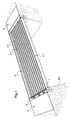
figure 1 est une vue d'ensemble, selon un premier mode de réalisation de l'invention, des coffrages avant bétonnage pour la réalisation d'un tablier de pont ; - la
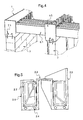
figure 2 est une vue du coffrage d'appui pour la réalisation d'un tablier de pont selon le mode de réalisation de lafigure 1 ; - la
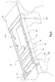
figure 3 est une vue représentant un coffrage de poutre de structure lié par un profilé d'étanchéité en C à un coffrage de rive pour la réalisation d'un tablier de pont ou un plancher selon le mode de réalisation de lafigure 1 ; - la
figure 4 est une vue d'ensemble des coffrages avant bétonnage d'un deuxième mode de réalisation de l'invention pour la confection d'un plancher ; - La
figure 5 est une vue représentant un coffrage de poutre de structure lié par un profilé d'étanchéité en Π à un coffrage de rive pour la réalisation d'un tablier de pont ou d'un plancher ; - la
figure 6 est une vue d'ensemble, en perspective partiellement écorchée, des coffrages avant bétonnage pour la réalisation d'une passerelle conformément à un troisième mode de réalisation de l'invention; - la
figure 7 est une vue du coffrage d'appui pour la réalisation d'une passerelle selon le mode de réalisation de lafigure 6 ; - la
figure 8 est une vue en coupe représentant un coffrage de poutre de structure lié par un élément transversal à un autre coffrage de poutre de structure pour la réalisation d'une passerelle selon le mode de réalisation de lafigure 6 ; - la
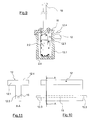
figure 9 est une vue en coupe d'une poutre de structure munie d'un chaperon de protection, selon le mode de réalisation de lafigure 6 ; - la
figure 10 est une vue d'ensemble représentant un élément transversal, selon le mode de réalisation de lafigure 6 . - la
figure 11 est une vue représentant la section de l'élément transversal de lafigure 10 .
- the
figure 1 is an overview, according to a first embodiment of the invention, formwork before concreting for the realization of a bridge deck; - the
figure 2 is a view of the support formwork for the realization of a bridge deck according to the embodiment of thefigure 1 ; - the
figure 3 is a view showing a structural beam formwork bonded by a C-shaped sealing profile to an edge formwork for the realization of a bridge deck or floor according to the embodiment of thefigure 1 ; - the
figure 4 is an overview of formwork before concreting a second embodiment of the invention for making a floor; - The
figure 5 is a view showing a form of structural beam formwork connected by a sealing profile in Π to a formwork of bank for the realization of a bridge deck or a floor; - the
figure 6 is an overall view, in perspective partially broken away, formwork before concreting for the realization of a bridge in accordance with a third embodiment of the invention; - the
figure 7 is a view of the support formwork for the realization of a bridge according to the embodiment of thefigure 6 ; - the
figure 8 is a sectional view showing a structural beam formwork joined by a transverse element to another structural beam formwork for the realization of a bridge according to the embodiment of thefigure 6 ; - the
figure 9 is a sectional view of a structural beam provided with a protective chaperone, according to the embodiment of thefigure 6 ; - the
figure 10 is an overview showing a transverse element, according to the embodiment of thefigure 6 . - the
figure 11 is a view representing the section of the transverse element of thefigure 10 .
L'invention concerne un procédé de fabrication d'un ouvrage soutenu et un ensemble de coffrages à cet effet.The invention relates to a method of manufacturing a supported structure and a set of forms for this purpose.
Un premier mode de réalisation consiste en la construction d'un pont pour le franchissement d'une brèche d'environ douze mètres. Le pont est constitué de deux massifs désignés 100 et d'un tablier, généralement désigné 2, relié aux massifs 100 par ses extrémités. Dans ce premier mode de réalisation, les poutres de structure 2.1 sont des poutres de tablier 2.1.A first embodiment consists of the construction of a bridge for crossing a gap of about twelve meters. The bridge consists of two massifs designated 100 and an apron, generally designated 2, connected to the
L'ensemble de coffrages comprend plusieurs coffrages perdus en BFUP. Il comprend ainsi deux coffrages d'appui généralement désignés en 1, des coffrages de poutres de tablier 2.1 et des profilés d'étanchéité 2.3. Les surfaces intérieures des coffrages sont indentées de manière à assurer une bonne prise du béton coulé dans les coffrages perdus tandis que leurs surfaces extérieures destinées à être apparentes sont ici lisses pour conférer à l'ouvrage terminé son état de surface final.The formwork set includes several formwork lost in UHPC. It thus comprises two support forms generally designated as 1, formwork of deck beams 2.1 and sealing profiles 2.3. The interior surfaces of the formwork are indented to ensure a good grip of the poured concrete in the lost forms while their external surfaces intended to be visible here are smooth to give the finished work its final surface state.
Les coffrages de poutres de tablier 2.1 comprennent des plaques de BFUP assemblées les unes aux autres pour former deux âmes et un talon agencés selon un profil en U. Deux des coffrages de poutres de tablier sont destinés à former des rives du tablier, lesdits deux coffrages comportant des âmes de hauteurs différentes, l'âme la plus haute étant destinée à former un bord latéral du tablier. Les coffrages de poutres de tablier 2.1 comprennent, ici, des torons précontraints 2.4 s'étendant longitudinalement dans leur talon. Ces torons 2.4 renforcent la résistance longitudinale des coffrages de poutres de tablier 2.1 et sont dimensionnés pour permettre aux coffrages de poutres de tablier 2.1 de résister à la charge de ferraillage, de bétonnage et d'autoriser la circulation du personnel intervenant notamment pour réaliser des ferraillages transversaux.The apron beam formwork 2.1 comprises UHPC plates assembled to each other to form two webs and a heel arranged in a U-shaped profile. Two of the deck beam forms are intended to form the edges of the deck, said two forms having souls of different heights, the uppermost soul being intended to form a side edge of the apron. The formwork of apron beams 2.1 comprise, here, prestressed strands 2.4 extending longitudinally in their heel. These strands 2.4 reinforce the longitudinal strength of the deck beam formwork 2.1 and are dimensioned to allow the formwork of deck beams 2.1 to withstand the load of reinforcement, concreting and allow the movement of personnel involved in particular to achieve reinforcement transverse.
Chaque profilé d'étanchéité 2.3 est agencé de manière à réaliser l'étanchéité entre deux poutres de tablier 2.1 adjacentes. Chaque profilé d'étanchéité 2.3 a ainsi une forme de plaque pourvue de rebords latéraux et destinée à s'étendre à cheval sur les âmes en regard de deux poutres adjacentes, chaque rebord étant reçu entre les âmes d'une même poutre pour assurer le maintien latéral en position du profil d'étanchéité.Each sealing profile 2.3 is arranged so as to seal between two adjacent deck beams 2.1. Each sealing profile 2.3 thus has a plate shape provided with lateral flanges and intended to extend astride the souls facing two adjacent beams, each rim being received between the webs of the same beam to ensure the maintenance lateral in position of the sealing profile.
Le coffrage du tablier de pont 2 est ainsi constitué de coffrages de poutres de tablier 2.1 recevant des armatures 2.2 et chapeautés avec les coffrages adjacents par des profilés d'étanchéité 2.3. La hauteur finie du tablier est déterminée par la hauteur des âmes extérieures des coffrages de poutres de rives 2.5 qui est idéalement au même niveau que la hauteur des flancs des coffrages d'appui 1.The formwork of the bridge deck 2 thus consists of apron beam formwork 2.1 receiving reinforcement 2.2 and covered with adjacent forms by sealing profiles 2.3. The finished height of the deck is determined by the height of the outer webs of the bank beam formwork 2.5 which is ideally at the same level as the height of the flanks of the
Les deux coffrages d'appui 1 sont de forme parallélépipédique et comportent, sur leurs parois se faisant face de part et d'autre de la brèche à franchir, une série d'encoches destinées à accueillir les coffrages des poutres de tablier 2.1 et à les entretoiser. Le fond des coffrages d'appui est percé de plusieurs ouvertures 1.2 destinées à recevoir les attentes saillant des appuis. Avantageusement, les ouvertures 1.2 auront des dimensions permettant d'absorber les tolérances d'implantation et de verticalité des pieux 8. Des rondelles d'étanchéité 1.3, dont le diamètre intérieur permet d'engager la rondelle autour du pieu, sont positionnées avant l'implantation du coffrage d'appui 1. Le contour extérieur de ces rondelles 1.3 est adapté à la réalisation d'une étanchéité avec l'ouverture 1.2 qui peut être circulaire, carrée ou de forme quelconque et par exemple oblongue. Les rondelles d'étanchéité ont des dimensions externes supérieures à celles des ouvertures 1.2. Cette disposition évite des relevés sur site préalables. Ces coffrages de massifs 1 reçoivent avant bétonnage des cages d'armatures 1.4 positionnées à distance d'enrobage suffisante.The two
Dans un premier temps, les rondelles 1.3 sont implantées sur les attentes d'appui de part et d'autre de la brèche. Les coffrages 1 sont alors positionnés sur les têtes des pieux 8, les ouvertures 1.2 autorisant le passage des têtes de pieux et leur présence à l'intérieur du parallélépipède défini par chaque coffrage d'appui 1. Les rondelles 1.3 arrivent en recouvrement avec le fond du coffrage d'appui 1 et assurent une étanchéité pour le bétonnage futur. Un cordon de mastic de type adapté peut être posé à l'interface de ces 2 éléments le cas échéant.At first, the washers 1.3 are located on the support expectations on both sides of the gap. The
Les encoches 1.1 pratiquées dans le coffrage d'appui 1 sont orientées vers la brèche et se font face. Les axes des encoches seront idéalement alignés. Une cage d'armature 1.4 est ensuite disposée en fond de coffrage d'appui 1, à distance suffisante d'enrobage. Une première couche de béton est alors coulée, solidarisant le coffrage et la base de la cage de ferraillage avec les têtes des pieux. Le niveau de cette première couche est idéalement situé en dessous de la base des encoches 1.1.The notches 1.1 made in the
Une fois ce béton en cours de prise, les coffrages de poutres de tablier 2.1 sont disposés entre les deux coffrages d'appui 1 dans les encoches 1.1 se faisant face. Leur implantation ne nécessite aucun contrôle particulier, les encoches définissant d'elles-mêmes la position des coffrages de poutres de tablier 2.1. Ainsi, une implantation rigoureuse des coffrages d'appui permet d'implanter sans précaution particulière les coffrages de poutres de tablier 2.1. La rigidité de ces coffrages permet le déplacement du personnel sur ces poutres et ainsi autorise la pose des armatures longitudinales 2.2 dans les coffrages de poutres de tablier 2.1 à la main, permettant d'éviter l'utilisation de moyens de manutention puissants. Les âmes extérieures des coffrages des poutres de rives 2.5 du tablier 2 comprennent une surlongueur correspondant à l'épaisseur additionnelle du hourdis et de la voie de roulement. Un éventuel ferraillage complémentaire des coffrages d'appui 1 peut être ensuite réalisé.Once this concrete is in process, the formwork of deck beams 2.1 are arranged between the two
Les profilés d'étanchéité 2.3 sont positionnés de manière à relier les âmes adjacentes des coffrages de 2.1. Le coffrage du pont est alors complet. Les ferraillages transversaux peuvent alors être posés et le coulage du tablier commencer.The sealing profiles 2.3 are positioned to connect the adjacent webs of the forms of 2.1. The formwork of the bridge is then complete. The transversal reinforcement can then be laid and the pouring apron start.
Ce bétonnage a lieu idéalement en une seule phase et comble les coffrages d'appui 1 avec leurs armatures 1.4, les coffrages de poutres 2.1 avec leurs armatures 2.2. Les profilés d'étanchéité 2.3 permettent au béton de s'élever jusqu'au niveau final défini par la hauteur des flancs du coffrage d'appui 1 et des poutres de rive 2.5 du tablier 2. Une réserve peut être prévue pour la mise en place, après prise du béton, d'un revêtement de roulement tel que du bitume ou du macadam.This concreting takes place ideally in a single phase and fills the support forms 1 with their reinforcements 1.4, the formwork of beams 2.1 with their reinforcements 2.2. The sealing profiles 2.3 allow the concrete to rise to the final level defined by the height of the flanks of the
Des dalles de transition 4 préfabriquées en BFUP et soutenues par un remblais compacté sont posées en appui entre le pont et le remblais routier. Elles seront ensuite revêtues de la couche de roulement commune à la route et au pont. Pour des ouvrages de la portée du pont objet de ce mode de réalisation, les joints de chaussée et appuis néoprènes ne sont pas utiles.
Une fois que la prise du béton coulé lors de la seconde et dernière opération de bétonnage est achevée, le pont peut recevoir ses accessoires (garde-corps, couche de roulement, peinture de signalisation au sol, etc....).Once the pouring of the poured concrete during the second and final concreting operation is complete, the bridge can receive its accessories (railing, wearing course, ground signaling paint, etc.).
Un second mode de réalisation consiste en la construction de planchers de bâtiments. Le plancher repose par ses extrémités sur des appuis maçonnés: poteaux, poutres ou murs porteurs en saillie desquelles s'étendent des attentes métalliques. Dans ce second mode de réalisation les poutres de structures 2.1 sont des poutrelles 6.1. Le plancher 2 est constitué de deux coffrages d'appui 1 reliés par des poutrelles 6.1 et supportant un hourdis.A second embodiment consists of the construction of building floors. The floor rests on its ends on masonry supports: posts, beams or bearing walls projecting from which extend metal expectations. In this second embodiment, the beams of structures 2.1 are beams 6.1. The floor 2 consists of two
Les coffrages nécessaires à cette réalisation sont :
- des coffrages d'appui 1,
- des coffrages de poutrelles 6.1,
- des profilés d'étanchéité. 2.3,
- support forms 1,
- 6.1 beam formwork,
- sealing profiles. 2.3
Tous ces éléments sont réalisés en BFUP et comportent les mêmes dispositions constructives que les coffrages du mode de réalisation précédent notamment: surface intérieure indentée ou nervurée, torons longitudinaux précontraints 2.4, perçages 1.1 offrant la possibilité d'inclure le ferraillage des poutrelles 6.1 dans le coffrage...All these elements are made of UHPC and have the same construction arrangements as the formwork of the previous embodiment including: indented or ribbed inner surface, longitudinal strands preloaded 2.4, 1.1 holes providing the possibility to include the reinforcement beams 6.1 in the formwork ...
Dans cette application particulière, la réalisation d'un plancher soutenu par plusieurs appuis comme représenté en
Les coffrages d'appui 1 sont disposés sur des poteaux 7. Les appuis extrêmes reçoivent des coffrages 1, les appuis des travées intermédiaires reçoivent des coffrages d'appui 1.5. Tous ces coffrages d'appui sont pourvus en leur fond de découpes 1.2 permettant le passage des attentes 7.1 émergeant des poteaux 7. Ces coffrages positionnés, ils reçoivent les armatures 1.4 et sont partiellement bétonnés. Les coffrages de poutrelles 6.1 sont alors positionnés dans les encoches 1.1 et relient les coffrages 1 et 1.5. Les profilés d'étanchéités 2.3 sont mis en place entre les âmes adjacentes de deux poutrelles 6.1. Les éventuels ferraillages transversaux peuvent alors être installés. On notera que les âmes en surlongueur des coffrages de rives 2.5 peuvent être avantageusement remplacées par les parois des murs délimitant le bâtiment. L'ensemble des coffrages 1, 1.5, 6.1, 2.3, 2.5 ou les murs du bâtiment réalise un volume fermé dans lequel sont coulés simultanément le hourdis et les poutrelles du plancher.The support forms 1 are arranged on
Une fois la prise de cette phase de bétonnage achevée, le plancher est terminé.Once this concrete phase has been taken, the floor is finished.
Les éléments identiques ou analogues à ceux précédemment décrits porteront une référence numérique identique à ceux-ci dans la description qui suit d'un troisième mode de réalisation.Elements identical or similar to those previously described will bear a numerical reference identical to these in the description which follows of a third embodiment.
En référence aux
La réalisation de la passerelle 10 débute par la pose des rondelles d'étanchéité 1.3 sur les têtes des pieux 8. Les coffrages d'appui 1 sont ensuite positionnés sur les têtes de pieux 8 de manière à ce que les encoches 1.2 pratiquées dans chaque coffrage d'appui 1 soient orientées vers la brèche et que leurs axes soient alignés. Une cage d'armature 1.4 est ensuite disposée en fond de coffrage d'appui 1, à distance suffisante d'enrobage. Une première couche de béton est alors coulée, solidarisant le coffrage d'appui 1 et la base de la cage de ferraillage 1.4 avec les têtes des pieux 8. Le niveau supérieur de cette première couche est idéalement situé en dessous de la base des encoches 1.2.The realization of the
Une fois ce béton en cours de prise, les coffrages de nervure longitudinale 13.1 sont disposés entre les deux coffrages d'appui 1 dans les encoches 1.2 se faisant face. Leur implantation ne nécessite aucun contrôle particulier, les encoches 1.2 définissant d'elles-mêmes la position des coffrages de nervure longitudinale 13.1. Ainsi, une implantation rigoureuse des coffrages d'appui 1 permet d'implanter sans précaution particulière les coffrages de nervure longitudinale 13.1. La rigidité de ces coffrages permet le déplacement du personnel sur ceux-ci et ainsi autorise la pose des armatures longitudinales 2.2 dans les coffrages de nervures longitudinales 13.1 à la main, permettant d'éviter l'utilisation de moyens de manutention puissants. Une seconde phase de bétonnage est alors réalisée afin de remplir les coffrages de nervure longitudinale 13.1 jusqu'à l'arase de la partie inférieure de l'encoche 14. Les éléments transversaux 12 sont ensuite posés dans les encoches 14 correspondantes. Les attentes de ferraillage 12.3 viennent alors en saillie dans chaque coffrage de nervure longitudinale 13.1 un peu au dessus du niveau du béton précédemment coulé. La pose de ces éléments transversaux 12 peut se faire à l'avancement à partir d'un cadre mobile équipé d'un filet de sécurité et reposant sur les deux nervures longitudinales 13.1.Once this concrete is being set, the longitudinal rib formings 13.1 are arranged between the two
Une fois l'ensemble des éléments transversaux 12 posés dans les encoches 14, une dernière phase de bétonnage vient recouvrir les attentes de ferraillage 12.3 et achève de remplir les coffrages de nervure longitudinale 13.1 et les coffrages d'appui 1. Cette phase de bétonnage permet de sceller les éléments constitutifs de la passerelle 10 et leurs phases de bétonnage respectives: têtes de pieux 8, coffrages d'appui 1, coffrages de nervure longitudinale 13.1, éléments transversaux 12. En référence à la
On obtient ainsi une passerelle 10 dont le platelage 11 présente une résistance et une durabilité supérieures aux solutions de passerelle existantes.This provides a
Avantageusement, la partie supérieure 12.1 des éléments transversaux 12 comprend une surface supérieure 12.4 moulée sur matrice bois, donnant ainsi à l'élément transversal 12 l'aspect d'un platelage en bois. Le BFUP dans lequel est composé l'élément transversal 12.1 peut également être teinté afin de souligner encore l'aspect « bois » de celui-ci.Advantageously, the upper portion 12.1 of the
Ainsi, l'invention permet de réaliser, sans l'intervention de main d'oeuvre qualifiée ni moyens de levage lourds, des ouvrages soutenus en béton d'une manière rapide et économique. Ces ouvrages possèdent la caractéristique supplémentaire de permettre des coûts de maintenance quasi nuls, les armatures étant protégées par une peau en BFUP très durable. La résistance au feu est majorée par la peau en BFUP.Thus, the invention makes it possible to achieve, without the intervention of qualified labor or heavy lifting means, concrete structures supported in a fast and economical manner. These structures have the additional feature of allowing almost zero maintenance costs, the armatures being protected by a very durable UHPC skin. The fire resistance is increased by the skin in UHPC.
Bien entendu, l'invention n'est pas limitée aux modes de réalisation décrits mais englobe toute variante entrant dans le champ de l'invention telle que définie par les revendications.Of course, the invention is not limited to the embodiments described but encompasses any variant within the scope of the invention as defined by the claims.
En particulier :
- les coffrages peuvent intégrer des protrusions sur leurs faces internes destinées à caler les ferraillages à la distance d'enrobage minimale requise ainsi qu'à bloquer en position les armatures dans le coffrage ;
- les coffrages de poutres de structure 2.1 peuvent être moulés ou extrudé ;
- les coffrages de poutres de structure 2.1
ou d'appuis 1 peuvent intégrer, dès la préfabrication leurs armatures ; - les coffrages de poutres de structure 2.1 peuvent intégrer les profils d'étanchéité : une des deux âmes comporte un élément saillant perpendiculaire à l'âme et dirigé vers l'extérieur du coffrage. Cet élément est implanté de manière tangente à la partie supérieure de l'âme et a une longueur lui permettant de reposer sur une autre protrusion destinée à le recevoir et implantée sur l'âme de l'élément suivant ;
- les coffrages peuvent intégrer des oreilles ou poignées de manutention ou de levage, renforcées ou non d' armatures ;
- la section des coffrages de poutres de structure 2.1 peut être en I en T ou en TT avec l'intégration de tout ou partie du ferraillage nécessaire ;
- les coffrages peuvent ne pas contenir d'éléments de précontrainte ;
- les armatures peuvent être actives ou passives, éventuellement précontraintes lors de la préfabrication ou après bétonnage sur site ;
- l'espacement des coffrages de poutres de structure 2.1 peut être réalisé à l'aide de peignes de positionnement ;
- les plaques en BFUP peuvent recevoir, dès la préfabrication la finition définitive requise : enduite, lasurée, engravée ;
- les profilés d'étanchéité 2.3 peuvent avoir une section en Π (
figure 5 ) ; - bien que, ici, les encoches 14 reçoivent des éléments transversaux 12 dont la section est en T, l'invention s'applique également à d'autres formes d'encoche et de section de poutres correspondantes comme par exemple des sections rectangulaires, en L, en I ;
- bien qu'ici, la passerelle 10 ne comprenne que deux nervures longitudinales 13.1, l'invention s'applique également à une passerelle comprenant plus de deux nervures longitudinales, les nervures additionnelles étant pourvues sur leurs deux faces d'encoches accueillant des éléments transversaux 12 ;
- bien que, ici, les éléments transversaux 12 soient réalisés en BFUP, l'invention s'applique également à des éléments transversaux réalisés en d'autres matières comme par exemple la pierre, le bois, le métal, le béton standard ;
- bien que, ici, une face supérieure 12.4 de l'élément transversal 12.1 soit moulée sur matrice bois, l'invention s'applique également à des éléments transversaux n'ayant aucun moulage en partie supérieure ou portant d'autres types de moulages tels que indentations, larmes, rainures, ergots anti-dérapants ;
- bien que, ici, le chaperon de
protection 16 soit fixé au béton remplissant les nervures longitudinales 13.1 par scellement, l'invention s'applique également à d'autres modes de fixation comme le chevillage mécanique ou chimique ; - bien que, ici, un béton est coulé dans les nervures longitudinales 13.1 avant la pose des éléments transversaux 12, l'invention s'applique également à une unique phase de bétonnage solidarisant les armatures longitudinales 2.2, le coffrage de nervure longitudinale 13.1 et les éléments transversaux 12 avec les coffrages d'appui 1 et les massif 100.
- the formwork can incorporate protrusions on their internal faces intended to wedge the reinforcement to the minimum required coating distance and to lock in position the reinforcement in the formwork;
- structural beam formwork 2.1 may be molded or extruded;
- the formwork of structural beams 2.1 or supports 1 can integrate, from the prefabrication their armatures;
- Structural beams formwork 2.1 can integrate the sealing profiles: one of the two cores comprises a projecting element perpendicular to the core and directed outwardly of the formwork. This element is implanted tangentially to the upper part of the core and has a length allowing it to rest on another protrusion intended to receive it and implanted on the soul of the next element;
- the formwork may incorporate lugs or handles for handling or lifting, reinforced or not with reinforcements;
- the section of structural beam formwork 2.1 may be I T or TT with the integration of all or part of the necessary reinforcement;
- the formwork may not contain prestressing elements;
- the reinforcements may be active or passive, possibly prestressed during prefabrication or after concreting on site;
- the spacing of structural beam formwork 2.1 can be achieved by means of positioning combs;
- the plates in UHPC can receive, as soon as prefabrication, the final finish required: coated, stained, engraved;
- the sealing profiles 2.3 may have a section in Π (
figure 5 ); - although, here, the
notches 14 receivetransverse elements 12 whose section is T, the invention also applies to other forms of notch and section of corresponding beams such as rectangular sections, L in I; - although here, the
bridge 10 comprises only two longitudinal ribs 13.1, the invention also applies to a bridge comprising more than two longitudinal ribs, the additional ribs being provided on their two faces with notches hostingtransverse elements 12 ; - although, here, the
transverse elements 12 are made of UHPC, the invention also applies to transverse elements made of other materials such as stone, wood, metal, standard concrete; - although, here, an upper face 12.4 of the transverse element 12.1 is molded on a wood matrix, the invention also applies to transverse elements having no molding at the top or carrying other types of moldings such as indentations, tears, grooves, anti-slip lugs;
- although, here, the
protective chaperon 16 is fixed to the concrete filling the longitudinal ribs 13.1 by sealing, the invention also applies to other modes of attachment such as mechanical or chemical pinning; - although, here, a concrete is poured into the longitudinal ribs 13.1 before the laying of the
transverse elements 12, the invention also applies to a single concrete phase solidarisant the longitudinal reinforcement 2.2, the longitudinal rib formwork 13.1 and the elements transverse 12 with the support forms 1 and thesolid mass 100.
Claims (23)
Applications Claiming Priority (1)
| Application Number | Priority Date | Filing Date | Title |
|---|---|---|---|
| FR1156593A FR2978176B1 (en) | 2011-07-20 | 2011-07-20 | METHOD OF MAKING A SUSTAINED SLAB AND SET OF FORMWORK FOR CARRYING OUT SAID METHOD |
Publications (2)
| Publication Number | Publication Date |
|---|---|
| EP2549028A1 true EP2549028A1 (en) | 2013-01-23 |
| EP2549028B1 EP2549028B1 (en) | 2016-04-13 |
Family
ID=46178501
Family Applications (1)
| Application Number | Title | Priority Date | Filing Date |
|---|---|---|---|
| EP12171393.7A Not-in-force EP2549028B1 (en) | 2011-07-20 | 2012-06-08 | Method for manufacturing a suspended structure and set of formworks for implementing same |
Country Status (3)
| Country | Link |
|---|---|
| EP (1) | EP2549028B1 (en) |
| CA (1) | CA2783596C (en) |
| FR (1) | FR2978176B1 (en) |
Cited By (4)
| Publication number | Priority date | Publication date | Assignee | Title |
|---|---|---|---|---|
| EP2821552A1 (en) * | 2013-07-04 | 2015-01-07 | Conseil Service Investissement | Gateway and method for producing such a gateway |
| EP3298216A4 (en) * | 2015-05-21 | 2018-05-16 | Lifting Point Pre-Form Pty Limited | A module for a structure |
| CN113136992A (en) * | 2021-04-30 | 2021-07-20 | 上海二十冶建设有限公司 | Method for accurately forming high-altitude large-inclination-angle flexible formwork tied concrete wall |
| CN115059024A (en) * | 2022-07-09 | 2022-09-16 | 水利部交通运输部国家能源局南京水利科学研究院 | Simply supported box type water conveying and transferring combined structure adopting interlocking connection and construction method |
Families Citing this family (1)
| Publication number | Priority date | Publication date | Assignee | Title |
|---|---|---|---|---|
| CN114197323B (en) * | 2022-01-11 | 2024-03-01 | 江西省交通工程集团有限公司 | Double-layer shaping steel template with adjustable support cushion stone elevation and construction method |
Citations (2)
| Publication number | Priority date | Publication date | Assignee | Title |
|---|---|---|---|---|
| FR633832A (en) * | 1927-05-03 | 1928-02-04 | Brev De Construction S A Et | Further training in the manufacture of reinforced concrete floors |
| DE2554888A1 (en) * | 1975-12-05 | 1977-06-08 | Esli James Forrest | Multi stage reinforced concrete beam casting - includes base layer partially set before adding tensioning members followed by upper layers |
-
2011
- 2011-07-20 FR FR1156593A patent/FR2978176B1/en not_active Expired - Fee Related
-
2012
- 2012-06-08 EP EP12171393.7A patent/EP2549028B1/en not_active Not-in-force
- 2012-07-19 CA CA2783596A patent/CA2783596C/en not_active Expired - Fee Related
Patent Citations (2)
| Publication number | Priority date | Publication date | Assignee | Title |
|---|---|---|---|---|
| FR633832A (en) * | 1927-05-03 | 1928-02-04 | Brev De Construction S A Et | Further training in the manufacture of reinforced concrete floors |
| DE2554888A1 (en) * | 1975-12-05 | 1977-06-08 | Esli James Forrest | Multi stage reinforced concrete beam casting - includes base layer partially set before adding tensioning members followed by upper layers |
Cited By (9)
| Publication number | Priority date | Publication date | Assignee | Title |
|---|---|---|---|---|
| EP2821552A1 (en) * | 2013-07-04 | 2015-01-07 | Conseil Service Investissement | Gateway and method for producing such a gateway |
| FR3008111A1 (en) * | 2013-07-04 | 2015-01-09 | Conseil Service Investissements | GATEWAY AND METHOD OF MAKING SUCH A GATEWAY |
| EP3298216A4 (en) * | 2015-05-21 | 2018-05-16 | Lifting Point Pre-Form Pty Limited | A module for a structure |
| US10323368B2 (en) | 2015-05-21 | 2019-06-18 | Lifting Point Pre-Form Pty Limited | Module for a structure |
| US10619315B2 (en) | 2015-05-21 | 2020-04-14 | Lifting Point Pre-Form Pty Limited | Module for a structure |
| US11053647B2 (en) | 2015-05-21 | 2021-07-06 | Lifting Point Pre-Form Pty Limited | Module for a structure |
| US11598056B2 (en) | 2015-05-21 | 2023-03-07 | Inquik Ip Holdings Pty Ltd | Module for a structure |
| CN113136992A (en) * | 2021-04-30 | 2021-07-20 | 上海二十冶建设有限公司 | Method for accurately forming high-altitude large-inclination-angle flexible formwork tied concrete wall |
| CN115059024A (en) * | 2022-07-09 | 2022-09-16 | 水利部交通运输部国家能源局南京水利科学研究院 | Simply supported box type water conveying and transferring combined structure adopting interlocking connection and construction method |
Also Published As
| Publication number | Publication date |
|---|---|
| FR2978176B1 (en) | 2013-09-06 |
| EP2549028B1 (en) | 2016-04-13 |
| FR2978176A1 (en) | 2013-01-25 |
| CA2783596A1 (en) | 2013-01-20 |
| CA2783596C (en) | 2014-12-30 |
Similar Documents
| Publication | Publication Date | Title |
|---|---|---|
| EP2549028B1 (en) | Method for manufacturing a suspended structure and set of formworks for implementing same | |
| US9988775B1 (en) | Concrete i-beam for bridge construction | |
| KR101314081B1 (en) | Retaining wall and upeer structure connection method for rahmen structure | |
| EP2794996B1 (en) | Prefabricated bridge | |
| US9422680B2 (en) | Deck | |
| KR101277751B1 (en) | Precast Concrete Blocks and Remodeling Reinforcing Construction Methods for Low and Middle-rise Beam-column Buildings by Using that Blocks | |
| EP0244890B1 (en) | Process for producing hollow structures such as ducts, silos, or shelters, and structures obtained by this process | |
| EP0369914B1 (en) | Method for joining a matrix material to a functional support, and devices manufactured according to this method | |
| EP3170947A1 (en) | Pre-wall for building construction and method for manufacturing the pre-wall | |
| EP2231947B1 (en) | Prefabricated element for creating a reinforced concrete slab and slab thus created | |
| FR2973407A1 (en) | Thin ultra-high performance fiber reinforced concrete plate for formwork for constructing slab in building, has ribs and grooves for rigid support of counterpart e.g. reinforced concrete beam, in contact with plate | |
| KR20190046336A (en) | Sandwich precast concrete wall and manufacturing method thereof | |
| EP3020886A1 (en) | Method for fabricating a wall or walls of a building by casting, and a form system | |
| JP2021070949A (en) | Pile support structure and construction method thereof | |
| KR102012155B1 (en) | Prefabricated sidewalk of bridge and construction method using thereof | |
| WO2019145261A1 (en) | Composite construction | |
| FR2925088A1 (en) | Construction element e.g. bridge span, fabricating method for e.g. roadway, involves flowing concrete in reinforcement case by partially countersinking case to fabricate metallic outer beam that contains inner beam | |
| JP4505271B2 (en) | COMPOSITE MATERIAL FOR PRECAST STRUCTURE, PRECAST STRUCTURE, AND METHOD FOR PRODUCING PRECAST STRUCTURE | |
| JP2003147726A (en) | Construction method for composite floor system and floor system panel used in the same | |
| JP2000291195A (en) | Composite floor slab and construction method therefor | |
| KR102052626B1 (en) | Composite deck member and slab using the same | |
| JP2010281040A (en) | Steel concrete composite floor slab, panel for constructing the steel concrete composite floor slab, and construction method for steel concrete composite floor slab | |
| JP2009243075A (en) | Prestressed concrete mold form, foundation structure of building using the prestressed concrete mold form, and method of constructing the foundation structure | |
| FR2467923A2 (en) | Tied industrialised building frame - is formed by slab edge grooves and ducts with column reinforcement in slab at duct | |
| JPH084343A (en) | Garage |
Legal Events
| Date | Code | Title | Description |
|---|---|---|---|
| PUAI | Public reference made under article 153(3) epc to a published international application that has entered the european phase |
Free format text: ORIGINAL CODE: 0009012 |
|
| AK | Designated contracting states |
Kind code of ref document: A1 Designated state(s): AL AT BE BG CH CY CZ DE DK EE ES FI FR GB GR HR HU IE IS IT LI LT LU LV MC MK MT NL NO PL PT RO RS SE SI SK SM TR |
|
| AX | Request for extension of the european patent |
Extension state: BA ME |
|
| 17P | Request for examination filed |
Effective date: 20130704 |
|
| RBV | Designated contracting states (corrected) |
Designated state(s): AL AT BE BG CH CY CZ DE DK EE ES FI FR GB GR HR HU IE IS IT LI LT LU LV MC MK MT NL NO PL PT RO RS SE SI SK SM TR |
|
| GRAP | Despatch of communication of intention to grant a patent |
Free format text: ORIGINAL CODE: EPIDOSNIGR1 |
|
| INTG | Intention to grant announced |
Effective date: 20150521 |
|
| GRAP | Despatch of communication of intention to grant a patent |
Free format text: ORIGINAL CODE: EPIDOSNIGR1 |
|
| INTG | Intention to grant announced |
Effective date: 20151021 |
|
| GRAS | Grant fee paid |
Free format text: ORIGINAL CODE: EPIDOSNIGR3 |
|
| GRAA | (expected) grant |
Free format text: ORIGINAL CODE: 0009210 |
|
| RAP1 | Party data changed (applicant data changed or rights of an application transferred) |
Owner name: CONSEIL SERVICE INVESTISSEMENTS |
|
| AK | Designated contracting states |
Kind code of ref document: B1 Designated state(s): AL AT BE BG CH CY CZ DE DK EE ES FI FR GB GR HR HU IE IS IT LI LT LU LV MC MK MT NL NO PL PT RO RS SE SI SK SM TR |
|
| REG | Reference to a national code |
Ref country code: GB Ref legal event code: FG4D Free format text: NOT ENGLISH |
|
| REG | Reference to a national code |
Ref country code: AT Ref legal event code: REF Ref document number: 790339 Country of ref document: AT Kind code of ref document: T Effective date: 20160415 Ref country code: CH Ref legal event code: EP Ref country code: CH Ref legal event code: NV Representative=s name: BOVARD AG, CH |
|
| REG | Reference to a national code |
Ref country code: IE Ref legal event code: FG4D Free format text: LANGUAGE OF EP DOCUMENT: FRENCH |
|
| REG | Reference to a national code |
Ref country code: DE Ref legal event code: R096 Ref document number: 602012016966 Country of ref document: DE |
|
| REG | Reference to a national code |
Ref country code: FR Ref legal event code: PLFP Year of fee payment: 5 |
|
| REG | Reference to a national code |
Ref country code: LT Ref legal event code: MG4D |
|
| REG | Reference to a national code |
Ref country code: AT Ref legal event code: MK05 Ref document number: 790339 Country of ref document: AT Kind code of ref document: T Effective date: 20160413 |
|
| REG | Reference to a national code |
Ref country code: NL Ref legal event code: MP Effective date: 20160413 |
|
| PG25 | Lapsed in a contracting state [announced via postgrant information from national office to epo] |
Ref country code: FI Free format text: LAPSE BECAUSE OF FAILURE TO SUBMIT A TRANSLATION OF THE DESCRIPTION OR TO PAY THE FEE WITHIN THE PRESCRIBED TIME-LIMIT Effective date: 20160413 Ref country code: NO Free format text: LAPSE BECAUSE OF FAILURE TO SUBMIT A TRANSLATION OF THE DESCRIPTION OR TO PAY THE FEE WITHIN THE PRESCRIBED TIME-LIMIT Effective date: 20160713 Ref country code: PL Free format text: LAPSE BECAUSE OF FAILURE TO SUBMIT A TRANSLATION OF THE DESCRIPTION OR TO PAY THE FEE WITHIN THE PRESCRIBED TIME-LIMIT Effective date: 20160413 Ref country code: NL Free format text: LAPSE BECAUSE OF FAILURE TO SUBMIT A TRANSLATION OF THE DESCRIPTION OR TO PAY THE FEE WITHIN THE PRESCRIBED TIME-LIMIT Effective date: 20160413 Ref country code: LT Free format text: LAPSE BECAUSE OF FAILURE TO SUBMIT A TRANSLATION OF THE DESCRIPTION OR TO PAY THE FEE WITHIN THE PRESCRIBED TIME-LIMIT Effective date: 20160413 |
|
| PG25 | Lapsed in a contracting state [announced via postgrant information from national office to epo] |
Ref country code: PT Free format text: LAPSE BECAUSE OF FAILURE TO SUBMIT A TRANSLATION OF THE DESCRIPTION OR TO PAY THE FEE WITHIN THE PRESCRIBED TIME-LIMIT Effective date: 20160816 Ref country code: LV Free format text: LAPSE BECAUSE OF FAILURE TO SUBMIT A TRANSLATION OF THE DESCRIPTION OR TO PAY THE FEE WITHIN THE PRESCRIBED TIME-LIMIT Effective date: 20160413 Ref country code: GR Free format text: LAPSE BECAUSE OF FAILURE TO SUBMIT A TRANSLATION OF THE DESCRIPTION OR TO PAY THE FEE WITHIN THE PRESCRIBED TIME-LIMIT Effective date: 20160714 Ref country code: RS Free format text: LAPSE BECAUSE OF FAILURE TO SUBMIT A TRANSLATION OF THE DESCRIPTION OR TO PAY THE FEE WITHIN THE PRESCRIBED TIME-LIMIT Effective date: 20160413 Ref country code: HR Free format text: LAPSE BECAUSE OF FAILURE TO SUBMIT A TRANSLATION OF THE DESCRIPTION OR TO PAY THE FEE WITHIN THE PRESCRIBED TIME-LIMIT Effective date: 20160413 Ref country code: AT Free format text: LAPSE BECAUSE OF FAILURE TO SUBMIT A TRANSLATION OF THE DESCRIPTION OR TO PAY THE FEE WITHIN THE PRESCRIBED TIME-LIMIT Effective date: 20160413 Ref country code: SE Free format text: LAPSE BECAUSE OF FAILURE TO SUBMIT A TRANSLATION OF THE DESCRIPTION OR TO PAY THE FEE WITHIN THE PRESCRIBED TIME-LIMIT Effective date: 20160413 Ref country code: ES Free format text: LAPSE BECAUSE OF FAILURE TO SUBMIT A TRANSLATION OF THE DESCRIPTION OR TO PAY THE FEE WITHIN THE PRESCRIBED TIME-LIMIT Effective date: 20160413 |
|
| PG25 | Lapsed in a contracting state [announced via postgrant information from national office to epo] |
Ref country code: BE Free format text: LAPSE BECAUSE OF NON-PAYMENT OF DUE FEES Effective date: 20160630 Ref country code: IT Free format text: LAPSE BECAUSE OF FAILURE TO SUBMIT A TRANSLATION OF THE DESCRIPTION OR TO PAY THE FEE WITHIN THE PRESCRIBED TIME-LIMIT Effective date: 20160413 |
|
| REG | Reference to a national code |
Ref country code: DE Ref legal event code: R097 Ref document number: 602012016966 Country of ref document: DE |
|
| PG25 | Lapsed in a contracting state [announced via postgrant information from national office to epo] |
Ref country code: CZ Free format text: LAPSE BECAUSE OF FAILURE TO SUBMIT A TRANSLATION OF THE DESCRIPTION OR TO PAY THE FEE WITHIN THE PRESCRIBED TIME-LIMIT Effective date: 20160413 Ref country code: DK Free format text: LAPSE BECAUSE OF FAILURE TO SUBMIT A TRANSLATION OF THE DESCRIPTION OR TO PAY THE FEE WITHIN THE PRESCRIBED TIME-LIMIT Effective date: 20160413 Ref country code: RO Free format text: LAPSE BECAUSE OF FAILURE TO SUBMIT A TRANSLATION OF THE DESCRIPTION OR TO PAY THE FEE WITHIN THE PRESCRIBED TIME-LIMIT Effective date: 20160413 Ref country code: EE Free format text: LAPSE BECAUSE OF FAILURE TO SUBMIT A TRANSLATION OF THE DESCRIPTION OR TO PAY THE FEE WITHIN THE PRESCRIBED TIME-LIMIT Effective date: 20160413 Ref country code: SK Free format text: LAPSE BECAUSE OF FAILURE TO SUBMIT A TRANSLATION OF THE DESCRIPTION OR TO PAY THE FEE WITHIN THE PRESCRIBED TIME-LIMIT Effective date: 20160413 Ref country code: MC Free format text: LAPSE BECAUSE OF FAILURE TO SUBMIT A TRANSLATION OF THE DESCRIPTION OR TO PAY THE FEE WITHIN THE PRESCRIBED TIME-LIMIT Effective date: 20160413 |
|
| PLBE | No opposition filed within time limit |
Free format text: ORIGINAL CODE: 0009261 |
|
| STAA | Information on the status of an ep patent application or granted ep patent |
Free format text: STATUS: NO OPPOSITION FILED WITHIN TIME LIMIT |
|
| PG25 | Lapsed in a contracting state [announced via postgrant information from national office to epo] |
Ref country code: SM Free format text: LAPSE BECAUSE OF FAILURE TO SUBMIT A TRANSLATION OF THE DESCRIPTION OR TO PAY THE FEE WITHIN THE PRESCRIBED TIME-LIMIT Effective date: 20160413 |
|
| 26N | No opposition filed |
Effective date: 20170116 |
|
| REG | Reference to a national code |
Ref country code: IE Ref legal event code: MM4A |
|
| PG25 | Lapsed in a contracting state [announced via postgrant information from national office to epo] |
Ref country code: IE Free format text: LAPSE BECAUSE OF NON-PAYMENT OF DUE FEES Effective date: 20160608 Ref country code: SI Free format text: LAPSE BECAUSE OF FAILURE TO SUBMIT A TRANSLATION OF THE DESCRIPTION OR TO PAY THE FEE WITHIN THE PRESCRIBED TIME-LIMIT Effective date: 20160413 |
|
| REG | Reference to a national code |
Ref country code: FR Ref legal event code: PLFP Year of fee payment: 6 |
|
| PG25 | Lapsed in a contracting state [announced via postgrant information from national office to epo] |
Ref country code: HU Free format text: LAPSE BECAUSE OF FAILURE TO SUBMIT A TRANSLATION OF THE DESCRIPTION OR TO PAY THE FEE WITHIN THE PRESCRIBED TIME-LIMIT; INVALID AB INITIO Effective date: 20120608 Ref country code: CY Free format text: LAPSE BECAUSE OF FAILURE TO SUBMIT A TRANSLATION OF THE DESCRIPTION OR TO PAY THE FEE WITHIN THE PRESCRIBED TIME-LIMIT Effective date: 20160413 |
|
| REG | Reference to a national code |
Ref country code: FR Ref legal event code: PLFP Year of fee payment: 7 |
|
| PG25 | Lapsed in a contracting state [announced via postgrant information from national office to epo] |
Ref country code: TR Free format text: LAPSE BECAUSE OF FAILURE TO SUBMIT A TRANSLATION OF THE DESCRIPTION OR TO PAY THE FEE WITHIN THE PRESCRIBED TIME-LIMIT Effective date: 20160413 Ref country code: LU Free format text: LAPSE BECAUSE OF NON-PAYMENT OF DUE FEES Effective date: 20160608 Ref country code: MT Free format text: LAPSE BECAUSE OF FAILURE TO SUBMIT A TRANSLATION OF THE DESCRIPTION OR TO PAY THE FEE WITHIN THE PRESCRIBED TIME-LIMIT Effective date: 20160413 Ref country code: MK Free format text: LAPSE BECAUSE OF FAILURE TO SUBMIT A TRANSLATION OF THE DESCRIPTION OR TO PAY THE FEE WITHIN THE PRESCRIBED TIME-LIMIT Effective date: 20160413 Ref country code: IS Free format text: LAPSE BECAUSE OF FAILURE TO SUBMIT A TRANSLATION OF THE DESCRIPTION OR TO PAY THE FEE WITHIN THE PRESCRIBED TIME-LIMIT Effective date: 20160413 |
|
| PG25 | Lapsed in a contracting state [announced via postgrant information from national office to epo] |
Ref country code: BG Free format text: LAPSE BECAUSE OF FAILURE TO SUBMIT A TRANSLATION OF THE DESCRIPTION OR TO PAY THE FEE WITHIN THE PRESCRIBED TIME-LIMIT Effective date: 20160413 |
|
| PGFP | Annual fee paid to national office [announced via postgrant information from national office to epo] |
Ref country code: CH Payment date: 20180621 Year of fee payment: 7 Ref country code: DE Payment date: 20180625 Year of fee payment: 7 |
|
| PG25 | Lapsed in a contracting state [announced via postgrant information from national office to epo] |
Ref country code: AL Free format text: LAPSE BECAUSE OF FAILURE TO SUBMIT A TRANSLATION OF THE DESCRIPTION OR TO PAY THE FEE WITHIN THE PRESCRIBED TIME-LIMIT Effective date: 20160413 |
|
| PGFP | Annual fee paid to national office [announced via postgrant information from national office to epo] |
Ref country code: GB Payment date: 20180620 Year of fee payment: 7 |
|
| REG | Reference to a national code |
Ref country code: DE Ref legal event code: R119 Ref document number: 602012016966 Country of ref document: DE |
|
| REG | Reference to a national code |
Ref country code: CH Ref legal event code: PL |
|
| GBPC | Gb: european patent ceased through non-payment of renewal fee |
Effective date: 20190608 |
|
| PG25 | Lapsed in a contracting state [announced via postgrant information from national office to epo] |
Ref country code: DE Free format text: LAPSE BECAUSE OF NON-PAYMENT OF DUE FEES Effective date: 20200101 Ref country code: GB Free format text: LAPSE BECAUSE OF NON-PAYMENT OF DUE FEES Effective date: 20190608 |
|
| PG25 | Lapsed in a contracting state [announced via postgrant information from national office to epo] |
Ref country code: CH Free format text: LAPSE BECAUSE OF NON-PAYMENT OF DUE FEES Effective date: 20190630 Ref country code: LI Free format text: LAPSE BECAUSE OF NON-PAYMENT OF DUE FEES Effective date: 20190630 |
|
| PGFP | Annual fee paid to national office [announced via postgrant information from national office to epo] |
Ref country code: FR Payment date: 20210622 Year of fee payment: 10 |
|
| PG25 | Lapsed in a contracting state [announced via postgrant information from national office to epo] |
Ref country code: FR Free format text: LAPSE BECAUSE OF NON-PAYMENT OF DUE FEES Effective date: 20220630 |